EP2787861B1 - Improvements in and relating to cushions - Google Patents
Improvements in and relating to cushions Download PDFInfo
- Publication number
- EP2787861B1 EP2787861B1 EP12808876.2A EP12808876A EP2787861B1 EP 2787861 B1 EP2787861 B1 EP 2787861B1 EP 12808876 A EP12808876 A EP 12808876A EP 2787861 B1 EP2787861 B1 EP 2787861B1
- Authority
- EP
- European Patent Office
- Prior art keywords
- cushion
- user
- pillow
- trunk portion
- trunk
- Prior art date
- Legal status (The legal status is an assumption and is not a legal conclusion. Google has not performed a legal analysis and makes no representation as to the accuracy of the status listed.)
- Active
Links
Images


Classifications
-
- A—HUMAN NECESSITIES
- A47—FURNITURE; DOMESTIC ARTICLES OR APPLIANCES; COFFEE MILLS; SPICE MILLS; SUCTION CLEANERS IN GENERAL
- A47C—CHAIRS; SOFAS; BEDS
- A47C7/00—Parts, details, or accessories of chairs or stools
- A47C7/36—Supports for the head or the back
- A47C7/38—Supports for the head or the back for the head, e.g. detachable
-
- A—HUMAN NECESSITIES
- A47—FURNITURE; DOMESTIC ARTICLES OR APPLIANCES; COFFEE MILLS; SPICE MILLS; SUCTION CLEANERS IN GENERAL
- A47G—HOUSEHOLD OR TABLE EQUIPMENT
- A47G9/00—Bed-covers; Counterpanes; Travelling rugs; Sleeping rugs; Sleeping bags; Pillows
- A47G9/10—Pillows
- A47G9/1081—Pillows comprising a neck support, e.g. a neck roll
-
- A—HUMAN NECESSITIES
- A47—FURNITURE; DOMESTIC ARTICLES OR APPLIANCES; COFFEE MILLS; SPICE MILLS; SUCTION CLEANERS IN GENERAL
- A47C—CHAIRS; SOFAS; BEDS
- A47C27/00—Spring, stuffed or fluid mattresses or cushions specially adapted for chairs, beds or sofas
- A47C27/08—Fluid mattresses
- A47C27/086—Fluid mattresses with fluid-like particles, e.g. filled with beads
-
- A—HUMAN NECESSITIES
- A47—FURNITURE; DOMESTIC ARTICLES OR APPLIANCES; COFFEE MILLS; SPICE MILLS; SUCTION CLEANERS IN GENERAL
- A47C—CHAIRS; SOFAS; BEDS
- A47C7/00—Parts, details, or accessories of chairs or stools
- A47C7/36—Supports for the head or the back
- A47C7/38—Supports for the head or the back for the head, e.g. detachable
- A47C7/383—Detachable or loose head- or neck-supports, e.g. horse-shoe shaped
-
- A—HUMAN NECESSITIES
- A47—FURNITURE; DOMESTIC ARTICLES OR APPLIANCES; COFFEE MILLS; SPICE MILLS; SUCTION CLEANERS IN GENERAL
- A47G—HOUSEHOLD OR TABLE EQUIPMENT
- A47G9/00—Bed-covers; Counterpanes; Travelling rugs; Sleeping rugs; Sleeping bags; Pillows
- A47G9/10—Pillows
-
- B—PERFORMING OPERATIONS; TRANSPORTING
- B60—VEHICLES IN GENERAL
- B60N—SEATS SPECIALLY ADAPTED FOR VEHICLES; VEHICLE PASSENGER ACCOMMODATION NOT OTHERWISE PROVIDED FOR
- B60N2/00—Seats specially adapted for vehicles; Arrangement or mounting of seats in vehicles
- B60N2/80—Head-rests
- B60N2/882—Head-rests detachable
-
- A—HUMAN NECESSITIES
- A47—FURNITURE; DOMESTIC ARTICLES OR APPLIANCES; COFFEE MILLS; SPICE MILLS; SUCTION CLEANERS IN GENERAL
- A47G—HOUSEHOLD OR TABLE EQUIPMENT
- A47G9/00—Bed-covers; Counterpanes; Travelling rugs; Sleeping rugs; Sleeping bags; Pillows
- A47G9/10—Pillows
- A47G2009/1018—Foam pillows
Definitions
- the invention relates to cushions, particularly though not exclusively to portable travel pillows such as those for supporting the resting head of a traveller sat in a generally upright vehicle seat during a journey.
- Cushions for use in supporting the resting head of a seated person are often referred to as travel pillows, even though they are not limited in their use by people in the act of travelling.
- cushion designs may provide comfort when ideally positioned about the person of the user, it is not uncommon that the shaping of the cushion is not conducive to maintaining that ideal position without some effort by the user.
- a common problem is the slipping of a cushion from the shoulder of a user where, ideally, the cushion should remain if it is to support the resting head of a user effectively. Users typically resort to attempting to hold the cushion in place by hand or by urging a shoulder upwardly to sandwich the cushion between head and shoulder. This inevitably brings discomfort.
- Other designs may provide means for retaining a cushion in the intended position about a user. These can involve structures and shapes added to, or formed by, the cushion which reduce its versatility and/or ease of comfortable use. For example, complex and elaborate shapes designed to keep a cushion in place often limit the range of positions a user can place the cushion about their person in use.
- a further problem for some existing travel cushions used to support the head is the need either to be tethered around the user, or tied or attached to the back of the chair occupied by the user. Both requirements are very inconvenient.
- Other travel pillows are U-shaped to prevent them slipping away from the user when worn. However, when the user falls asleep their head will tend to either fall sidewards or forwards.
- the U-shaped cushion lacks support to prevent the users head from falling forward and resulting in neck strain.
- US5064245A1 discloses a cushion according to the preamble of claim 1.
- the present invention desirably aims to provide a secure, versatile and comfortable cushion for supporting the resting head of a user in a generally upright seat or the like.
- the present invention provides a cushion according to claim 1.
- the invention provides a cushion including: a pillow portion having a front side and an opposite rear side, and defining a support surface on the front side which is useable for supporting the head of a user of the cushion; and an elongate trunk portion that extends away from the pillow portion from said rear side and which is usable for supporting the chin of the user; wherein the pillow portion is shaped so that it is useable to extend from at least a position on the back of the neck of a user whose head is being supported by the pillow portion that is less than three centimetres from the mid-point of the back of the neck to at least a position where it contacts an ear of the user, and wherein in this use of the pillow portion the trunk portion extends away from the pillow portion towards the chin of the user.
- the cushion may simultaneously contact and provide support for the back of the neck of the user, a portion of the side of the head of the user between the back of their neck and their ear, and also for the chin of the user. In this manner, the cushion may securely and comfortably support the resting head of the user.
- the present invention can be considered as providing a cushion having a first portion for providing support simultaneously for the back of the neck of a user of the cushion and the side of the head of the user, and a second portion that extends from the first portion for providing support for the chin of the user.
- the present invention can be considered as providing a cushion having a first portion for contacting and providing support for the back of the neck of a user of the cushion, a second portion for contacting and providing support for the side of the head of the user, and a third portion for providing support for the chin of the user.
- references are made to the cushion being used or usable by a user, these references refer to an averagely sized human person, e.g. with an averagely proportioned neck and head.
- the pillow portion may be shaped so that it is usable to extend from at least a position on the back of the neck of a user whose head is being supported by the pillow portion that is less than three centimetres from the mid-point of the back of the neck to at least cover the mid-point of an ear of the user.
- the pillow portion may effectively support the side of the head of the user.
- the pillow portion may cover the opening of the ear canal of the ear of the user.
- the pillow portion may cover a portion of the ear extending from the opening of the ear canal to a position at least three centimetres above the opening of the ear canal.
- the pillow portion may cover a large part of the ear.
- the pillow portion may extend beyond the ear of the user.
- the pillow portion may be shaped so that it is useable to extend from at least the mid-point of the back of the neck of a user whose head is being supported by the pillow portion to at least a position where it contacts an ear of the user. That is, rather than extending to a position on the back of the neck of a user whose head is being supported by the pillow portion that is less than three centimetres from the mid-point of the back of the neck, the pillow portion may instead extend to at least the mid-point of the back of the neck. Thus, the back of the neck of the user may be effectively supported by the pillow portion.
- the pillow portion may extend across the mid-point of the back of the neck to a position beyond the mid-point of the back of the neck. Thus, the back of the neck of the user may be more effectively supported by the pillow portion.
- the trunk portion of the cushion is configured (e.g. sized and/or shaped) so that it is usable to contact the underside of the chin of a user whose head is being supported by the pillow.
- the trunk portion may provide support for the chin of the user from below the chin, in addition to e.g. providing support for the chin of the user from the side of the chin.
- the trunk portion may extend to contact at least the mid-point of the underside of the chin of the user. Indeed, the trunk portion may extend across the mid-point of the chin.
- the trunk portion may be configured so that in one use a top part of the trunk portion contacts the region where the top of the neck joins the jaw, and the underside of the chin is supported by a side portion of the trunk.
- the pillow portion may project from the trunk portion transversely to the elongation of the trunk portion, i.e. the trunk portion may protrude or stick out from a side or sides of the trunk portion, so that it is wider than a width of the elongate trunk portion.
- the pillow portion may project from the trunk portion transversely to the elongation of the trunk portion from two opposite sides of the trunk portion, i.e. the trunk portion may protrude or stick out from two opposite sides of the trunk portion, so that the pillow portion effectively extends transversely across the trunk portion, e.g. in a "T" or "J" shape, when viewed from the appropriate angle.
- the pillow portion is formed at a first end of the elongate length of the trunk portion.
- the trunk portion may taper towards a second end of the elongate length of the trunk portion, e.g. a width of the trunk portion may reduce progressively towards the second end of the elongate trunk portion.
- the second end of the elongate trunk portion which may be a terminal end of the elongate trunk portion, is a narrow part of the trunk portion and may be of a suitable size to be comfortably positioned against or under the chin of the user, to provide support for the chin of the user.
- the trunk portion may instead be substantially unexpanded at its second end, so that the width of the trunk portion at its second end is substantially the same as the width at e.g. the mid-point of the trunk portion, and the width of the trunk portion may maintain a substantially uniform value towards the second end thereof.
- the cushion is substantially symmetrical, so that the pillow portion is usable to support the head of a user from either side of the head of the user.
- the cushion may be used interchangeably to support the head of the user from either the left side or the right side of the head of the user, depending on the user's preference and the environment in which the cushion is being used, without requiring any significant modification or adjustment.
- the cushion may be substantially symmetrical about a plane bisecting the pillow portion and containing the trunk portion.
- a first side of the pillow portion provides a surface that is usable to support the head of a user of the cushion, and the trunk portion extends away from the pillow portion from a second side of the pillow portion opposite to the first side.
- the trunk portion extending from the pillow portion from the opposite side to the first side may provide extra support to the first side, so that the user's head can be better supported, e.g. some of the force applied to the first side of the pillow portion may be transmitted into the trunk portion.
- the trunk portion is formed curved or with a bend therein. Put another way, the trunk portion is formed so that its rest shape is a curved or bent shape, so that force is required to deform the trunk portion into a different shape.
- the trunk portion is able to curve around the side of the user's head, thereby providing a more comfortable and better support for the user's head, without requiring a force to be applied by the user to maintain the curved or bent shape of the trunk portion.
- the cushion may have a recess adapted to engage, in use, the shoulder of a user whose head is being supported by the cushion.
- the recess may be a suitably shaped cavity, depression or notch.
- the cushion may be more easily positioned on the shoulder of a user and may be more securely sited on the shoulder of the user, so that the cushion is less likely to move or fall away from the user, e.g. if the user falls asleep or moves.
- "Engage the shoulder” may mean that the recess is substantially positioned where the bottom of the neck meets the edge of the shoulder, e.g. the cleft of the neck.
- the recess may also provide added comfort to the user by helping the pillow to closely abut a side of the user's neck, thereby providing support for the side of the user's head, the back of the neck and the chin.
- the recess may be defined by a join between the trunk portion and a periphery of the pillow portion, e.g. the recess may be a corner formed by the meeting of an edge of the trunk portion and an edge of the pillow portion.
- the join between the trunk portion and the periphery of the pillow portion may make an angle of between 45 and 135 degrees.
- the join between the trunk portion and the periphery of the pillow portion may make an angle of approximately 90 degrees.
- the recess may be shaped so that it is a close fit to the shoulder of the user, so that the cushion is less likely to move or be dislodged from the shoulder.
- the force of the user's head on the pillow portion may squeeze the cushion against the user's shoulder, whereby the recess positioned around the shoulder may help to maintain the cushion in place on the shoulder.
- the trunk portion may be configured so that it is usable to extend across the underside of the chin of a user whose head is being supported by the pillow portion, i.e. the trunk portion may extend from one side of the chin to a point at or beyond the other side of the chin.
- the trunk portion may support the entirety of the underside of the chin of the user.
- the pillow portion may be shaped so that it is usable to cover a majority of the back of the neck of a user whose head is being supported by the pillow portion (e.g. more than 75% of the back of the neck of the user, or substantially the whole of the back of the neck of the user).
- the pillow portion may extend substantially across the majority of the back of the neck of the user from substantially a first side of the neck to substantially a second side of the neck, thus providing support for the majority of the back of the neck of the user.
- the pillow portion may extend across substantially the whole of the back of the neck of the user.
- the pillow portion may be shaped so that it is usable to extend from substantially the back of a side of the head of a user whose head is being supported by the cushion to substantially the front of the side of the head.
- the pillow portion may extend along substantially the whole length of the side of the head of the user and provide support for substantially the whole length of the side of the head of the user.
- the cushion may include an internal partition part separating an inner volume of the pillow portion from an inner volume of the trunk portion.
- the pillow portion and trunk portion may be separate volumes. The separation of the pillow portion and trunk portion into separate volumes may allow for different materials, or different densities of materials, to be used in the pillow portion and the trunk portion, e.g. so that their respective properties can be optimised for their intended purposes.
- the internal partition may be positioned to separate the end of the trunk portion that joins the pillow portion from the pillow portion.
- the trunk portion is formed with a bend in a part of its elongate length, wherein the degree of bend at said part may be greater than any degree of bend formed elsewhere in the trunk portion.
- Said part may be a bend-part of the elongate trunk.
- a localised bend in the length of the trunk portion as opposed to e.g. a smooth curvature along the entire length of the trunk portion, may enable the trunk portion to more closely match the side of the users head, e.g. to curve around the edge of a jaw of the user.
- Some or all parts of the elongate length of the trunk portion extending to a terminal end of the trunk portion from the bend-part may be substantially linear.
- the bend-part may define a bend resulting in an angular deviation of the elongate length of the trunk portion exceeding 90 degrees.
- the bend-part may define a bend resulting in an angular deviation of the elongate length of the trunk portion of substantially 90 degrees.
- the bend-part may define a bend resulting in an angular deviation of the elongate length of the trunk portion of less than 90 degrees.
- the cushion may comprise two or more fastening means that are fastenable together to retain the pillow portion in a folded state.
- the pillow portion may be secured in a folded state in which the size of the pillow portion is reduced, in order to make transportation of the pillow, e.g. in a person's luggage, easier.
- the two or more fastening means may comprise a first foldable tab possessing first attachment apparatus spaced from and adjacent to a second foldable tab possessing second attachment apparatus, wherein the pillow portion is foldably deformable to position the first tab to foldably overlap a surface part of the second tab to bring the first and second fastening apparatus into mutual engagement to fasten together thereby to retain the pillow portion in the folded state.
- first and second fastening means may comprise first and second magnets. These magnets may be sewn into opposite sides of the pillow portion, so that the pillow portion can be maintained in a folded configuration by folding the pillow portion so that the magnets come into contact and are fastened together.
- fastening means may be replaced with other fastening means that would be known to the skilled person, for example a toggle and loop arrangement or a popper arrangement.
- the trunk portion may be adjustably deformable by the user to form a curve or bend in the trunk portion, which curve or bend is substantially maintained after the deformation, i.e. the trunk portion may be shaped by a user into a curved or bent shape which then becomes the rest shape of the trunk portion.
- the cushion may initially be in a flat state, e.g. for ease of packing and transportation of the cushion. The user may then deform the trunk portion into a shape that is suitable for their head size and shape, to provide comfortable support for their head.
- the cushion may include a slip-resistant material formed at a part of the exterior surface thereof, i.e. a material that has a high coefficient of friction or that provides a good grip on an external surface.
- a slip-resistant material formed at a part of the exterior surface thereof, i.e. a material that has a high coefficient of friction or that provides a good grip on an external surface.
- the cushion may be less likely to slip or to move when the cushion is pressed against a surface by a user, e.g. a headrest of a chair.
- the trunk portion may also be usable for supporting the back of the neck of the user, i.e. the trunk portion may have a second role/use, as an alternative to the first role/use discussed above, in which it is usable to support the back of the neck of the user.
- the trunk portion may be configured so that it is also usable to hook around the back of the neck of the user.
- the trunk portion may be used to curve around part of all of the back of the neck of the user to provide support for the back of the neck of the user.
- the pillow portion may be shaped so that it is also usable to extend from at least a side of the chin of a user whose head is being supported by the pillow portion to at least contact an ear of the user.
- the pillow portion may have a second role/use, as an alternative to the first role/use discussed above, in which it is used to provide support for at least a side of the chin of the user and for a region of the side of the head of the user extending at least up to an ear of the user.
- the cushion may be usable in a second configuration in which the trunk portion contacts and supports the back of the neck of the user, and in which the pillow portion contacts and supports both a side of the chin of the user and a region of the side of the head of the user extending at least up to an ear of the user.
- the cushion may comprise a cushion case stuffed or filled with compliant material.
- the cushion may easily be made to have a desired density and resilience by stuffing it with an appropriate type and amount of material.
- the pillow portion may project (i.e. stick out or protrude) transversely (i.e. sideways) from a side of the trunk portion by a distance of at least 5 cm.
- the pillow portion may project transversely from a side of the trunk portion by a distance of at least 10 cm.
- the size of the pillow portion may be such that it extends from the trunk portion sufficiently to support both the side of the head of the user and the back of the head or neck of the user.
- the pillow portion may present a support surface for supporting the head of the user with a surface area of at least 200 square centimetres.
- the support surface may have a surface area of at least 250 square centimetres.
- the size of the support surface may be sufficient to securely support both the side of the head of a user of the cushion and the back of the head or neck of the user.
- the support surface may be substantially crescent shaped, e.g. so that it may curve about the shoulder of a user of the pillow.
- the pillow portion itself may be crescent shaped (e.g. with curved upper and lower edges).
- the pillow portion may have a longest length, i.e. a longest single dimension of the pillow portion, of at least 20 cm.
- the pillow portion may have a longest length of at least 25 cm Therefore, the length of the pillow portion may be sufficient for the pillow portion to extend from the back of the head or neck of the user across the side of the user's face, so as to provide better support for the user's head.
- the pillow portion may present a support surface for supporting the head of a user that is concavely curved (inwardly curved), i.e. the support surface may have a central part that is recessed or depressed relative to the edges of the support surface.
- This configuration of the support surface may enable the support surface to better fit against and support the head of the user, therefore making the cushion more comfortable for the user, e.g. compared to a support surface that bulges outwards in the centre.
- the trunk portion may have a cross-sectional shape that is substantially oval, ovoid or circular towards a terminal end of the trunk portion.
- the cross-sectional shape of the trunk portion may be optimised to support the user's chin.
- the cushion may comprise attachment means for separably attaching the cushion to an article, e.g. a pole, a head-rest of a seat-belt. Attaching the cushion to an article may remove the need for the user to hold or grip the cushion, and therefore may make it less likely that the cushion will move or fall away from the user, e.g. if the user falls asleep.
- the attachment means may comprise a first foldable tab possessing first fastening apparatus spaced from and adjacent to a second foldable tab possessing second fastening apparatus wherein the first tab is foldable to overlap a surface part of the second tab to bring the first and second fastening apparatus into mutual engagement to fasten together thereby to fasten the first and second tabs together to permit the head-support cushion thereby to attach to an article located in the space between the tabs.
- the cushion may be easily and securely fastened to an article, e.g. to a support rod or a seatbelt of a vehicle.
- the cushion may include a separate cushion support shaft separably attachable to the head-support cushion via the attachment means.
- the trunk portion may have an axial end-to-end length of at least 18 cm. Alternatively, the trunk portion may have an end-to-end length of at least 25 cm. Thus, the trunk portion may be sufficiently long to extend to at least contact the chin of the user, to provide support for the user's chin.
- the trunk portion and/or the pillow portion may be resiliently compliant.
- the cushion may provide comfortable support for the user by deforming somewhat to match the shape of the user's head and neck when the user's head or neck applies a force to it.
- the pillow portion may be shaped so that, in use, it completely covers the ear of a user whose head is being supported by the pillow portion. Thus, the pillow portion may support a majority of the side of the head of the user.
- the cushion may be a head-support cushion, a head-support pillow or a head-support travel pillow.
- the pillow portion may be defined by a lateral expansion formed at one end of the trunk portion which projects from the trunk portion so as to extend transversely to opposite sides of the trunk portion to present a terminal surface defining a head support surface adjacent to the trunk portion, and the cushion may be configured so that when the trunk portion is hooked under the chin of a user of the cushion the head support surface is positioned diagonally down along the side of the head of the user in a direction adjacent the user's eye and extending down past the user's ear, and a part of the head support surface is bent to curve behind the back of the user's head so that it forms a cushion for the lower back of the user's head and neck to rest on.
- the cushion is configured so that when the trunk portion is hooked under the chin of a user of the cushion the head support surface is positioned diagonally down along the side of the head of the user in a direction adjacent the user's eye and extending down past the user's ear, and a part of the head support surface is bent to curve behind the back of the user's head so that it forms a cushion for the lower back of the user's head and neck to rest on.
- this permits the trunk portion to support the chin of the user while the head support surface supports a side of the resting head of the user.
- the cushion need not be tethered. Placing the cushion between the user and a surface (e.g. a high back chair, a wall, a window etc) to lean against has been found to retain the cushion on position. The shaping of the cushion has been found to be exceptionally conducive to retaining its position about the person of the user in such natural circumstances.
- the trunk portion is preferably resiliently compliant.
- the pillow portion may project from the trunk portion such that the head support surface extends in a direction generally transverse to an elongation of the trunk portion.
- the elongation of the trunk portion may hook in a direction generally transverse to the head support surface thereby to position a terminal end of the trunk portion adjacent to the head support surface. Accordingly, this structuring permits the trunk portion to engage the head or neck of the user while the head support surface supports a side of the head of the user, in use.
- the trunk in the first position the trunk may be positioned to curl/hook under the user's chin.
- the pillow portion may be positioned above a shoulder at the side of the head in this case.
- the trunk may be positioned to hook/curl around the nape of the neck with the pillow portion at, and somewhat forward of, the shoulder adjacent the jaw and chin of the user.
- the trunk may engage with the user to retain its position whilst providing chin support and comfort.
- the trunk portion is adjustably deformable by the user to bend (e.g. become hooked) in shape, and desirably to retain the bent shape.
- the cushion may be made and sold with a substantially straight trunk portion, which is adjustable to bend (e.g. hooked form) to suit the comfort of the user.
- a suitable foam or axial/longitudinal wire insert such as would be apparent to those skilled in the art, may be employed in the trunk portion which serves to reversibly or adjustably retain a given shape to which the user deforms it in use.
- the invention may provide a cushion for supporting the head of a user, comprising: an elongate trunk portion and a pillow portion defined by a lateral expansion formed at one end of the trunk portion which projects from the trunk portion so as to extend transversely to opposite sides of the trunk portion to present a terminal surface defining the front side of the pillow portion adjacent to the trunk portion, wherein the trunk portion is adjustably deformable by the user to bend, and; wherein, the cushion is configured so that when the trunk portion is hooked under the chin of a user of the cushion the head support surface is positioned diagonally down along the side of the head of the user in a direction adjacent the user's eye and extending down past the user's ear, and a part of the head support surface is bent to curve behind the back of the user's head so that it forms a cushion for the lower back of the users head and neck to rest on.
- the trunk portion extends from a side of the pillow portion reverse to the side thereof defining said head support surface.
- the pillow portion may project from either side of the trunk portion such that the head support surface extends transversely across the trunk portion.
- the trunk may be formed to fan-out or spread out laterally at, or adjacent to, one end to provide an expansive head support panel on a side of the pillow portion.
- the head support surface may be positioned diagonally down (e.g. in a direction adjacent the user's eye and extending down past the ear) along the side of the head.
- the compliance and deformability of the pillow portion enables a part of this head support surface to be bent to curve behind the back of the user's head so that it:
- the trunk portion may hook around the nape of the neck (which the user may keep it in place when leaning back against a support surface such as a high backed chair) and the head support surface consequently extends diagonally downwardly adjacent to the user's cheek (e.g. from the eye down to under the side of the chin). Consequently, the side of the head and chin are supported.
- the cushion is kept in place by the user leaning back against the trunk portion.
- the cushion is preferably substantially symmetrical about a plane bisecting the cushion portion and containing the elongated trunk portion.
- a width of the trunk portion may be tapered to reduce progressively towards the terminal end thereof.
- the cushion may define a corner recess adapted to engage, in use, a shoulder of a user, the corner recess being defined by the convergence to a join between the trunk portion and a periphery of the pillow portion nearest the terminal end of the trunk portion.
- a peripheral edge of the pillow portion presented away from the terminal (i.e. free) end of the trunk is preferably arched.
- the trunk portion may define/follow a bend (e.g. be hooked) shaped to be substantially continuously curved along the elongate length of the trunk portion.
- a bend e.g. be hooked
- the cushion may comprise a cushion case stuffed or filled with compliant material.
- the cushion may be a travel pillow.
- the cushion may comprise a slip-resistant material at parts of the exterior surface thereof. This permits the exterior surface of the cushion to better grip or engage with a support surface against which the cushion may be urged, rested or wedged by the user in use - such as against a high-backed chair, a window or wall.
- slip-resistant material include PVC (Polyvinyl Chloride), foam, or rubber or other material such as would be apparent and available to the skilled person.
- the slip-resistant material may be arranged on the exterior surface of the pillow portion. Preferably, the slip-resistant material is arranged at and/or around those parts of the pillow portion reverse to the support panel - e.g. those parts from which the trunk portion extends.
- the cushion In use, it is typically these parts of the cushion which are urged against a support surface as a user positions his/her head against the support panel. By providing slip-resistance at that surface of the cushion, it is rendered better able to retain the position desired by the user.
- the slip-resistant material may be applied in liquid to the fabric of the exterior surface of the cushion (or of a cushion cover/case worn by the cushion) during manufacture so that it penetrates the fabric and becomes embedded therein. Subsequent solidification by curing or hardening results in an external area of the cushion (or the cushion case/cover) having a much higher coefficient of friction than that of the cushion fabric within which it is embedded.
- the slip-resistant material may be provided on the cushion in the form of an array of a plurality of isolated spots, patches of stripes separated by regions of the fabric of the exterior surface of the cushion (or cushion case). This means that the fabric of the cushion (or case) can retain its elasticity between the patches of slip-resistant material to allow the cushion to remain compliant in response to pressure from the user's head etc.
- the cushion in any of its aspects as well as supporting the resting head, may also support the chin when used in a first way, therefore stopping the head from falling forward.
- the cushion When used in a second way, it supports the head, back of the neck and chin, as described above.
- the present invention aims to address this problem.
- the cushion When used the first way, the cushion supports the head from falling to the side and also supports the chin, therefore preventing the head from falling forward.
- the cushion may do this in three ways.
- the pillow portion When the pillow is used the second way, leaning back against the trunk portion around the nape of the neck not only supports the traveller's neck preventing neck strain but also helps keep the pillow in place. Keeping the pillow portion in place prevents the head from falling to the side.
- Feature (2) above in relation to the first way of use applies equally to the second way of use.
- the pillow portion now lies on the side of the head, the cheek and partly under the chin. This offers some support for the resting chin. If the chin and the head are supported, then the likelihood of the head falling forwards will be reduced.
- the cushion may comprise an internal partition part separating an inner volume of the pillow portion from an inner volume of the trunk portion. This has been found to help the cushion retain its shape in use.
- the internal partition may be positioned to separate an end of the trunk portion which joins the pillow portion, from the pillow portion it joins. In this way, the partition prevents the contents of the trunk portion (e.g. stuffing) from migrating into the pillow portion and vice versa.
- the cushion has been found to much better retain its shape and firmness when the partition is so placed.
- the cushion may comprise a cushion case stuffed or filled with compliant material and the internal partition may be attached to the cushion case internally.
- the partition may be a panel of fabric attached (e.g. sown) to the cushion case internally to close-off the trunk portion from the pillow portion thereby to keep the contents (e.g. stuffing etc) of the two internal volumes separate.
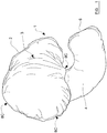
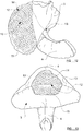
- Figures 1 to 4 illustrate, respectively, a perspective, front, back and side view of a travel pillow in the form of a cushion
- a cushion comprising a pillow portion (2) defining a head support surface (3) on the front side adapted and arranged for supporting a resting head of a user in a generally upright seat.
- the cushion possesses an elongated trunk portion (4) defining a resiliently compliant bend which extends from the pillow portion (2) to render the trunk generally hooked in shape at least towards a free end thereof distal from the pillow portion.
- the pillow portion projects from the trunk portion (4) such that the head support surface extends in a direction generally transverse to the elongation of the trunk portion.
- the elongation of the trunk portion is directed to follow a bend (i.e. to hook) in a direction generally transverse to the direction in which the head support surface extends to position a terminal end (6) of the trunk portion adjacent to the head support surface (3).
- the pillow portion (2) is shaped to define a pillow structure comprising on one side (shown) the head support panel (3) bounded by peripheral pillow edges defining a substantially semi-circular (e.g. "D" - shaped) boundary.
- the head support panel presents a broad surface which, although not completely flat, displays relatively little curvature other than adjacent to the periphery of the pillow structure.
- the width and depth of the head support panel exceed the thickness of the pillow structure of which it forms a part.
- the arched portion of the semi-circular pillow periphery is presented at one end of the cushion furthest from the terminal end (6) of the hooked trunk portion, while the substantially straight portion of the semi-circular pillow periphery is nearest to the terminal end of the hooked trunk.
- the outwardly-presented edge of the pillow portion has a curvature enabling the orientation of the pillow portion, and of the hooked trunk extending from it, to be adjusted by a user easily by rotation of the whole cushion without significant obstruction by that edge.
- the user may wish to rotate the cushion to achieve a more comfortable position whilst in an aircraft seat against which a part of the arched peripheral edge of the pillow portion abuts when the cushion is used.
- the arched nature of the pillow edge enables an adjacent part of the edge to be brought into abutment with the seat, by action of the user's adjustment of the cushion, without difficulty or obstruction by the pillow portion.
- the hooked trunk portion (4) defines a continuously curved cushion elongation extending from, and integrally formed with, a rear side (7 - Figure 3 ) of the pillow portion reverse to the side defining the head support surface (3).
- the trunk portion is substantially crescent-shaped.
- the trunk portion emerges from the rear side of the pillow portion as a diametric spine or ridge extending substantially from the mid-region of the arched peripheral edge of the pillow portion, along and across the rear side of the pillow portion to (and beyond) the substantially straight diametrical portion of the semi-circular peripheral edge of the pillow portion.
- the trunk portion (4) presents a ridge or spine which bisects the rear surface of the pillow portion. This adds strength to the cushion and renders the relative positioning and orientation of the pillow part and the hooked trunk part more robust and resilient - i.e. far less prone to sagging, deformation or floppiness of the pillow portion relative to the trunk portion.
- a corner recess (5A, 5B, Figure 2 ) is defined by the junction between the trunk portion and the pillow portion at the straight diametrical portion of the pillow edge. Each such corner recess serves to accommodate the shoulder of a user to help mount the cushion to the user more securely adjacent the head.
- the spine not only adds strength and robustness to the pillow but the thickness and width of it assist too.
- the thick spine and trunk support extends down over the shoulder and wedges in under the chin, resting against the users shoulder and on top of the clavicle keeping the pillow in place and the head from falling forward.
- the thickness of the top part of the spine over the shoulder helps provide support for the head when placed on the head support surface.
- the hooked trunk portion extends beyond the rear side of the pillow portion in a continuing arc which directs the trunk portion past the straight peripheral edge of the head support panel and onwards in a direction transverse to the panel to a terminal end located beyond the head support panel of the pillow portion.
- the terminal end of the hooked trunk portion is "visible" to the head support panel, being offset from the head support panel such that the trunk portion does not extend over it.
- the head support panel and the parts of the trunk portion visible to it define a structure adapted for receiving the side of a user's resting head (the head support panel) while concurrently supporting either the underside regions of the head (the hooked trunk portion) either to the front of the head under the chin, or to the rear of the head in the nape of the user's neck.
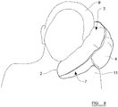
- Figures 5 to 7 illustrate the former support position of the cushion lodged over the shoulder (11) of a user in the chair (12) of a vehicle, wherein the head support panel (3) of the cushion portion (2) supports a side of a user's head (9) and the hooked trunk portion (4) hooks under the head to support the chin (10) of the user concurrently.
- the trunk portion (4) extends across the underside of the chin of the user of the cushion, to a point beyond the mid-point of the chin of the user.
- the trunk portion (4) provides support for substantially the whole of the underside of the chin of the user.
- the pillow portion (2) extends across substantially the whole of the side of the head of the user of the cushion, i.e. the pillow portion (2) extends from substantially the back of the head of the user to substantially the front of the head of the user, e.g. to a position just beyond the front of the face of the user.
- the ear of the user is completely covered by the pillow portion (2).
- the trunk portion (4) covers substantially the whole of the back of the neck of the user of the cushion, i.e. it extends from a left side of the back of the neck across and towards a right side of the back of the neck, so that the majority of the back of the neck from the left side to the right side is covered by the trunk portion (4).
- the cushion simultaneously contacts and provides support for the back of the neck of the user, the side of the head of the user, and the underside of the chin of the user.
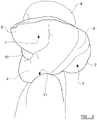
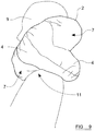
- Figures 8 to 10 illustrate the latter support position of the cushion lodged over the shoulder (11) of a user in the chair (not shown) of a vehicle, wherein the head support panel (3) of the cushion portion (2) supports a side of a user's head (9) and the hooked trunk portion (4) hooks under the head to support the nape of the neck ( Figure 10 , rear view of user) of the user concurrently.
- the cushion simultaneously contacts and provides support for the back of the neck of the user, the side of the head of the user, and the underside of the chin of the user.
- the cushion comprises a cushion case formed from three pieces of fabric joined at two seams (8C, 8D Figures 1 to 3 ) which enclose an inner volume of the case filled with compliant stuffing material.
- the fabric may be any suitably strong and light fabric for a cushion case as would be readily available to the skilled person.
- the exterior surface of the cushion could be made of fleece, cotton, denim etc.
- the back of it which will typically be resting against a support surface may have non slip material incorporated which may be important when used whilst in slippery leather chairs.
- the compliant stuffing material may be, but is not limited to, any one or more of: memory foam, buck wheat, micro beads, or any other padding material.
- Two of the three pieces of fabric are shaped to be mirror images of each other and to provide opposite halves of the trunk portion and rear surface (7) of the pillow portion. They are joined at a single seam (8D) which runs along the length of the trunk potion bisecting it and the rear pillow surface (7).
- a third of the three pieces of fabric defines the head support panel and is joined to the other two pieces of fabric at a semicircular seem (8C) which circumscribes the pillow portion along its semi-circular peripheral edge.
- an internal fabric panel which forms a partition between padding within the pillow portion and padding within the trunk portion.
- the internal panel may be joined by respective seams (8A, 8B) to the two fabric pieces defining the two halves of the rear pillow surface (7) symmetrically at opposite respective sides of the seam (8D) joining those two pieces wherein the respective seams extend from the semi-circular seam at the periphery of the pillow portion to the straight diametrical seam at the opposite periphery of the pillow portion, without connecting to the head support panel.
- Figure 12 illustrates a perspective view of a partially dissected cushion in which a part of the head support panel remains un-fixed to the pillow portion to reveal the internal partition panel (12).
- Dashed lines (13) identify the edges of the internal panel where it sown to the casing of the cushion to close-off the inner volume of the trunk portion from that of the pillow portion.
- the extreme peripheral edge of the internal panel is shown un-sown to the cushion casing, for clarity, to reveal some of the stuffing (14) held within the trunk portion.
- Stuffing (15) of the pillow portion is also shown.
- the internal panel and head support panel once fully sown, cover and contain the stuffing, and the internal panel fully partitions the trunk stuffing from the pillow stuffing.
- Figure 13 shows a top view of the cushion of Figure 12 with a top part artificially removed to reveal the internal panel and stuffing.
- the fabric panel partition creates two separate chambers - a trunk chamber, including the spine portion of the trunk extending along a surface of the pillow portion, and pillow chamber.
- the chamber defining the spine When the chamber defining the spine is stuffed with appropriate padding material it desirably forms a strong and defined spine which maintains its shape (typically more so than does the cushion without the panel partition).
- This spine part of the trunk chamber confines the stuffing (micro beads, padding etc) to the trunk, the stuffing cannot disperse into the pillow chamber as would be possible were the partition absent.
- the absence of a panel may permit stuffing to be displaced after repeated use causing deformation and sagging.
- the cushion When the cushion is used with the trunk placed under the user's chin, the arch of the trunk and one side of the pillow portion, slots over the arch of the shoulder and the centre area of the head support panel of the pillow portion forms a cushion for the side of the resting head. This is supported by the thick spine, which lies on top of the shoulder and underneath the pillow portion.
- the internal panel partition helps the spine maintain its strength and shape.
- a cushion without the panel partition and therefore perhaps, over time, without such a well-defined spine may not support the head as well as would the cushion having the partition. In such a case, potentially, the weight of the user's head may squash down the whole area putting strain on the neck. The squashiness of the cushion may worsen with repeated use.
- the internal panel partition forms two chambers.
- the spine chamber may be stuffed to capacity so that it forms a thick spine (and trunk) extending out from the back of the pillow portion.
- the amount of padding and thickness of the spine does not interfere with the shape of the pillow portion chamber since it is partitioned from the latter.
- the pillow portion may be stuffed independently and may be filled so that the pillow portion is slightly concaved in shape (a bulging pillow portion may not be comfortable for the resting head).
- the whole area (back and front of the pillow portion) has to be filled. This may make the top part of the pillow more conical in shape and the pillow portion area may bulge out. This tends not to be as comfortable for a resting head.
- the cross sectional profile of the trunk portion where the trunk is separate from the pillow portion is generally oval with the long oval axis generally parallel to the local radius of curvature of the hook shape of the trunk there.
- the trunk is generally wider in the dimension adapted to extend under the chin of the user - to provide a support platform - than in the dimension adapted to extend down from the chin, where less space is generally available to accommodate it between the chin and the chest of the resting user.
- the trunk is also tapered to narrow towards its terminal end.
- Figure 14 shows a view of a cushion according to an embodiment of the invention in which the trunk portion is shorter than in other embodiments.
- Figures 15A and 15B show top and side views of a cushion according to a further embodiment of the invention comprising a straight trunk portion (16) which is adjustably deformable by the user to retain a bent shape.
- the trunk portion may be adjustably bent by the user (e.g. become hooked), and to retain the bent shape.
- the cushion may be made and sold with a substantially straight trunk portion, which is adjustable to bend to suit the comfort of the user.
- a suitable foam or axial/longitudinal wire insert such as would be apparent to those skilled in the art, may be housed in, and extend along, the trunk portion which serves to reversibly or adjustably retain a given shape to which the user deforms it in use.
- Such an insert may extend from the end of the trunk portion adjacent the pillow portion to the other terminal end (or thereabouts), and may extend along substantially the full length of the trunk portion from the one end of the cushion (or thereabouts) to the other.
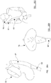
- Figure 16 illustrates an alternative cushion shape according to a preferred embodiment of the invention.
- the cushion (17) according to this embodiment comprises a trunk portion (19) which extends from the pillow portion (21) of the cushion (17) as a curved spine portion which executes a relatively sharp bend (23) of approximately or substantially 90° at a region of the trunk portion (19) between the pillow portion (21) and a terminal end (25) of the trunk portion (19).
- This substantially 90° bend (23) is executed over a limited region of the trunk portion (19) and those parts of the trunk portion (19) extending from the 90° bend region, to the terminal end of the trunk (25), are substantially straight in shape and form.
- the pillow portion (21) of the cushion (17) presents a generally convex head support surface (27) which generally bulges outwardly as a result of an appropriate amount of stuffing or padding material located underneath the head support surface (27) within the body of the pillow portion (21).
- the head support surface (27), and the pillow portion (21) itself, are generally crescent shaped.
- FIG. 17 A further alternative preferred embodiment of the invention is illustrated in Figure 17 .
- the trunk portion (29) executes an acute bend (31) in which the two parts of the trunk portion (29) either side of the acute bend (31) subtend between them an acute angle (less than 90°).
- This acute angle bend (31) is executed over a relatively short region of the trunk portion (29) such that those parts of the trunk portion (29) extending from the pillow portion (33) towards the acute bend region (31) define a gently curving spine portion, and those parts of the trunk portion (29) extending from the acute bend region (31) to a terminal end (25) of the trunk portion (29) are generally straight, although a gentle curvature may be provided on the outwardly-presented (i.e.
- the pillow portion (33) in this further preferred embodiment defines a concave head support surface (35) which presents to the user a recess (37) for receiving and supporting the user's head.
- trunk portion (29) between the acute bend region (31) and the terminal end (25) of the trunk portion (29) extend in a generally linear direction which, if extended beyond the terminal end (25) of the trunk portion (29), passes over the concavity (37) of the head support surface (35) of the pillow portion (33) thereby to generally point towards the head of a user when located in the recess (37) of the head support surface (35) in use.
- This arrangement serves to more effectively nuzzle the end of the trunk portion (25) under the chin or around the back of the neck of the user when used.
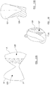
- Figure 18 illustrates another preferred embodiment of the invention in which the trunk portion (39) extends from the pillow portion (41) as a generally straight spine portion which executes an obtuse bend (42) from which the trunk portion (39) further extends to a terminal end (25) of the trunk portion (39) in a generally linear fashion.
- the angle subtended by the portions of the trunk, which meet at the obtuse bend (42), is greater than 90°.
- the pillow portion (41) in this preferred embodiment generally presents a "V" shape in which two lobes (43) of the pillow portion (41), which project laterally from the spine portion of the trunk portion (39), meet at an angle which is less than 180° such that the lobes (43) of the pillow portion (41) appear to "droop" in a direction towards the obtuse bend (42) in the trunk portion (39) of the cushion.
- the cushion (45) presents a generally oblong or rectangular-shaped pillow portion (47) from which extends a generally straight spine portion (49) which presents a bend (51) at its end, wherein the extreme end (53) of the trunk portion (49), following the bend (51), defines a shelf-like terminal surface (55) presenting a terminal surface generally facing in a direction extending towards or over the head support surface (57) of the pillow portion (47).
- Figures 16 to 19 are examples showing the types of pillow portions and trunk portions encompassed by the present invention. Of course, different combinations of pillow and trunk portions are encompassed by the present invention than those illustrated in Figures 16 to 19 .
- the pillow portion of Figure 16 could be combined with the trunk portion of Figure 19 .
- the pillow portion of Figure 17 could be combined with the trunk portion of Figure 18 , and so on.
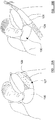
- FIGs 20, 21 and 22 illustrate a yet further preferred embodiment of the invention which is applicable to any one, some or all of the alternative cushion shapes described herein, in which attachment apparatus (59) are fixed to the extreme ends of the pillow portion (61) of the cushion at opposite sides.
- attachment apparatus (59) are fixed to the extreme ends of the pillow portion (61) of the cushion at opposite sides.
- a VelcroTM hook-bearing strap (63) is attached at a terminal end of the pillow portion (61) at one side, and upon a surface part of the pillow portion (61) from which the spine part of the trunk portion (65) of the cushion generally extends (i.e. the side reverse to the head support surface of the pillow portion).
- a hoop-bearing VelcroTM strip (67) adapted to receive a surface of the hook- bearing VelcroTM strip (63) so as to engage with and fasten to that strip in a manner as will be readily appreciated by the skilled person.
- a hoop (69) is formed at an edge of the pillow portion (61) mid way between the terminal ends of the pillow portion (61) on an edge of the pillow portion (61) opposite the edge from which the trunk portion (65) extends to form the aforementioned bend.
- the hoop (69) is provided so that the cushion can be attached to a user's luggage or other article when the cushion is not in use.
- the trunk portion (65) may be embraced by, and enveloped within, the two folded-over sides of the pillow portion (61) and the arrangement held in place by action of the hook-bearing and hoop-bearing VelcroTM strip portions (63, 67) fully engaged as shown in Figure 22 .
- the cushion may be compressed and rolled-up in order to reduce its size for packing within luggage of a traveller or user.
- a small element (60) may be provided above the VelcroTM strip (63) to hide the VelcroTM strip (63) when it is not in use.
- This element (60) may be a loop bearing VelcroTM patch to which the VelcroTM strip (63) is connectable. Alternatively, it may be a small pouch, recess or opening in which the VelcroTM strip (63) can be stored.
- the VelcroTM strips may be replaced with other fastening means, for example by two or more magnets, which may be positioned in substantially the same positions as the VelcroTM strips described above or may be positioned in a different arrangement.
- other fastening means known to a person skilled in the art could be used in place of the VelcroTM strips, for example a toggle and loop arrangement, or one or more poppers.
- Figures 23, 24, 25A and 25B show a further preferred embodiment of the invention employing the same principle as that shown in the embodiments of Figures 20 to 22 .
- the pillow portion (71) presents a head support surface (73) which is generally more triangular in shape (approximately speaking, and in general terms) whereby the edges of the head support surface (73) at the side of the pillow portion (71) from which the trunk portion (75) extends meet at an apex which points towards the bent, projecting portion of the trunk at an angle less than 180°.
- Each of these two edges is substantially straight or gently curved to a small degree along its length between the apex in question and the outermost extreme end of the pillow portion (71) to which that edge extends.
- the uppermost edge of the pillow portion (71) joining the extreme ends of the pillow portion, at opposite sides, is also only mildly convexly curved or approximately straight to a large extent.
- the pillow portion (71) is approximately triangular at its head support surface and tapers towards an approximately triangular apex at the trunk portion near-most the bend in the trunk.
- the two pillow portion lobes (77) of the pillow portion (71) may be caused to meet as shown in Figure 24 so as to press respective parts of the head support surface in direct contact together and hold the lobes (77) of the pillow portion (71) in that state using the VelcroTM fasteners (63, 67) described above with reference to Figures 20 to 22 .
- the VelcroTM fastener arrangement illustrated in Figures 23 to 25B is substantially the same as those shown in Figures 20 to 22 .
- Figures 26A, 26B and 26C , and Figures 27A, 27B and 27C , and Figures 28A, 28B and 28C show a further preferred embodiment of the present invention in which the cushion (79) includes an attachment apparatus (81) for use in attaching the cushion (79) to an elongate support structure (83) such as a support pole or a seatbelt strap.
- Figures 26A to 26C illustrate use of the attachment apparatus (81) in attaching the cushion (79) to a support pole (83), whereas figures 28A to 28C illustrate use of the attachment apparatus in attaching the cushion to the strap of a seatbelt in use.
- the cushion (81) comprises a first attachment panel (85) being a generally elongate panel attached at one elongate panel edge to the elongate spine portion of the trunk running in parallel to the spine at one side of the spine.
- One surface of the first panel has attached to it a strip (87) of hook-bearing VelcroTM material which extends along the elongate length of the first panel (85).
- a second panel (89) is provided as an elongate structure attached to the spine of the cushion (81) in register with the first panel at a side of the spine opposite to the side of the spine to which the first panel (85) is concurrently attached.
- a strip (91) of loop-bearing VelcroTM material is attached to one side of the second panel (89) so as to be positionable, by appropriately positioning the second pane (89), to engage with the hook-bearing VelcroTM strip (87) upon the first panel (85) when the first panel (85) is similarly appropriately positioned concurrently.
- the second panel portion (89) is adapted to be folded over the centre of the spine along those parts of the spine adjacent the elongate edge of the second strip which is joined to the spine at its side, and, subsequently, the first panel (85) is adapted to be similarly folded over that same portion of the spine such that the outwardly-presented loop-bearing VelcroTM strip (87) upon the second panel (85) engaged with the hook-bearing VelcroTM strip (91) upon the first panel (89) in order to connect with and attach together.
- the first (85) and second (89) panels may embrace and envelop an elongate object (83) between them and the portion of the spine they cover when folded over as shown in Figures 27B and 27C .
- the enveloped and embraced elongate object (83) may be held and gripped in position in this way.
- the elongate object (83) is a flexible pole which may be of a suitably flexible material to permit the user to flex the pole to adapt, to some extent, the contort of the user's body, without being so flexible as to be easily collapsed.
- the pole may be substantially cylindrical in its elongate length.
- the support pole may be sufficiently long to extend from the cushion (81) along the torso of the user's body and to the legs of the user's body when seated.
- the user may embrace, with his/her arms the mid region of the support pole and embrace the lower terminal end of the support pole between his/her thighs in order to assist in retaining the cushion in place at one side of the user's head as shown in Figure 26C .
- the elongate structure (83) embraced by the panels (85, 89) of the attachment apparatus may be a diagonal strap of a seatbelt of a user seated in a car or other vehicle employing such diagonal seatbelt straps which extend across the shoulder of a user, across their torso and down to the hip of the user at the opposite side of their body as shown schematically in Figure 28C .
- the diagonal strap of the seatbelt is able to retain the cushion at the side of the user's head in use as shown in Figures 28A to 28C .
- the attachment means includes a panel structure (101) that can be folded to produce a tubular structure or sleeve for positioning around an article, such as a seatbelt.
- the panel (101) of this embodiment has four fastening means (103) positioned towards the corners of the panel (101). Two of these fastening means are positioned on a first side of the panel (101) and two are positioned on a second opposite side of the panel (101).
- the fastening means comprise hook-bearing VelcroTM patches or strips (105) positioned on the first side of the panel and corresponding hoop-bearing VelcroTM patches or strips (107) positioned on the second side of the panel.
- the panel (101) can be positioned against a first side of a seatbelt (109).
- a first part (111) of the panel having the hoop-bearing VelcroTM patches or strips can then be folded over the seatbelt (109) to cover a second side of the seat belt (109).
- a second part (113) of the panel (101) having the hook-bearing VelcroTM patches or strips (105) can then be folded over the seatbelt (109) to cover the second side of the seatbelt (109) and to overlap the first part (111) of the panel (101).
- the hook-bearing VelcroTM patches or strips (105) are positioned so that when the second part (113) of the panel (101) is folded over to overlap the first part (111) of the panel (101) the hook-bearing VelcroTM patches or strips (105) overlap and contact the hoop-bearing VelcroTM patches or strips (107).
- the panel is securely fastened in a sleeve/tube configuration around the seatbelt (109), as illustrated in Figure 29C .
- the panel (101) has a large hook-bearing VelcroTM strip (115) on a surface thereof, such that when the panel (101) is formed as a sleeve/tube around the seatbelt (109) the large hook-bearing VelcroTM strip (115) is visible and presented on an external surface of the sleeve. As described later, this large hook-bearing VelcroTM strip (115) is used to secure the cushion to the sleeve. Of course, a plurality of smaller VelcroTM patches, or other fastening means, could be used in place of the large VelcroTM strip (115).
- the panel (101) can be formed into a sleeve around the seatbelt (109).
- the sleeve may be movable along the seatbelt (109) by a user, e.g. by sliding it along the seatbelt (109).
- the sleeve may tightly grip the seatbelt (109) so that it remains substantially in position on the seatbelt (109)
- a second part of the attachment means includes a panel structure (121) that can be folded to produce a removable tubular sleeve that can be positioned around the trunk of a cushion according to any one of the previously described embodiments.
- the panel (121) has corresponding first (123) and second (125) parts.
- a large hoop-bearing VelcroTM strip (127) is formed on the second part (125) of the panel (121). This hoop-bearing VelcroTM strip is for engaging and fastening to the large hook-bearing VelcroTM strip (115) on the seatbelt sleeve portion.
- the panel (121) is formed into a tubular sleeve (129) by folding the panel structure so that the first (123) and second (125) parts overlap (with the VelcroTM strip (127) on the outer side) and securing the first (123) and second (125) parts together along the edges (A).
- the edges (A) can be sewn together.
- a sleeve (129) is formed with a hoop-bearing VelcroTM strip on the external surface thereof.
- the completed sleeve (129) is shown in Figure 31B .
- the completed sleeve (129) can be positioned over the trunk portion (130) of a cushion according to any one of the previously described embodiments. This may be achieved by sliding the sleeve (129) along the trunk (130) of the cushion.
- the hoop-bearing VelcroTM strip (127) is positioned on the outside of the sleeve (127), and towards a side of the trunk portion (130), i.e. away from a centre line of the trunk portion (130).
- the sleeve (127) is pulled up over the trunk portion (130) of the cushion so that it covers the majority of the back of the spine, coming down under the sides of the pillow portion and to the front of the pillow to the area where the top of the trunk joins the pillow portion.
- a second hoop-bearing VelcroTM strip is positioned on a second side of the panel 121, directly opposite to and overlapping the hoop-bearing VelcroTM strip 127 (not visible in the Figures).
- the sleeve (129) can be turned inside out, so that it is usable on both seatbelts that extend across the body from the left of the body and on seatbelts that extend across the body from the right of the body, i.e. the sleeve (129) can be used with seatbelts that fasten either way.
- FIGS 35A and 35B The combination of both parts of the attachment means in use is shown in Figures 35A and 35B .
- the sleeve (129) is positioned about the trunk portion (130) with the hoop-bearing VelcroTM strip visible and positioned to one side of the trunk portion (130).
- the panel (101) is formed into a sleeve about the seatbelt (129) and is positioned so that the hook-bearing VelcroTM strip (115) on the panel (101) is in contact with and secured to the hoop-bearing VelcroTM strip (127) on the sleeve (129).
- the cushion is connected to/secured to the seatbelt (129) through the sleeve (129) about the trunk portion (130) and the sleeve about the seatbelt (129).
- the sleeve (129) can be turned inside out before being positioned on the trunk portion (130).
- FIGs 33A to 34 An alternative embodiment of the cushion is shown in Figures 33A to 34 .
- This embodiment of the pillow is intended for use particularly as a kid's pillow, for use by children, but is not limited to use in this way.
- the cushion (141) of this embodiment has a different shape pillow portion (143) to some of the previously described embodiments.
- the pillow portion (143) is approximately U-shaped when viewed from the front, with extended ear portions (145) that extend from the pillow portion (143) towards a terminal end of the trunk portion (147).
- the pillow portion (143) may be larger than the pillow portions of some of the previous embodiments, to provide a large pillow portion (143) for a child to rest their head on.
- the extended ear portions (145) are useable to cover more area at the back of the head or neck of the user and the trunk portion (147) is configured so that it is usable to curl further around a child's neck or chin.
- the centre part of the pillow portion (143) forms a distinct arch shape (149) above the trunk portion (147).
- This arch shape (149) allows the cushion to 'hook' more around the neck of a child in use, which will help keep it more in place.
- the pillow of this embodiment is preferably used with the seatbelt attachment means described above, so that the cushion can be secured in place relative to the user and form an effective cushion for the user's head.
Landscapes
- Engineering & Computer Science (AREA)
- Health & Medical Sciences (AREA)
- General Health & Medical Sciences (AREA)
- Otolaryngology (AREA)
- Pulmonology (AREA)
- Aviation & Aerospace Engineering (AREA)
- Transportation (AREA)
- Mechanical Engineering (AREA)
- Bedding Items (AREA)
- Mattresses And Other Support Structures For Chairs And Beds (AREA)
- Chair Legs, Seat Parts, And Backrests (AREA)
Applications Claiming Priority (3)
| Application Number | Priority Date | Filing Date | Title |
|---|---|---|---|
| GB201121215A GB201121215D0 (en) | 2011-12-09 | 2011-12-09 | Improvements in and relating to cushions |
| GB1208001.6A GB2499265B (en) | 2011-12-09 | 2012-05-04 | Improvements in and relating to cushions |
| PCT/GB2012/053062 WO2013084005A1 (en) | 2011-12-09 | 2012-12-07 | Improvements in and relating to cushions |
Publications (2)
| Publication Number | Publication Date |
|---|---|
| EP2787861A1 EP2787861A1 (en) | 2014-10-15 |
| EP2787861B1 true EP2787861B1 (en) | 2019-07-24 |
Family
ID=45541496
Family Applications (1)
| Application Number | Title | Priority Date | Filing Date |
|---|---|---|---|
| EP12808876.2A Active EP2787861B1 (en) | 2011-12-09 | 2012-12-07 | Improvements in and relating to cushions |
Country Status (17)
| Country | Link |
|---|---|
| US (3) | US9808100B2 (https=) |
| EP (1) | EP2787861B1 (https=) |
| JP (2) | JP6290093B2 (https=) |
| KR (1) | KR102059543B1 (https=) |
| CN (2) | CN104244772B (https=) |
| AU (2) | AU2012349858B2 (https=) |
| BR (1) | BR112014013840A2 (https=) |
| CA (1) | CA2858293C (https=) |
| DK (1) | DK2787861T3 (https=) |
| ES (1) | ES2752128T3 (https=) |
| GB (3) | GB201121215D0 (https=) |
| HK (1) | HK1203133A1 (https=) |
| IN (1) | IN2014CN04934A (https=) |
| MX (1) | MX352940B (https=) |
| NZ (1) | NZ720392A (https=) |
| RU (1) | RU2613874C2 (https=) |
| WO (1) | WO2013084005A1 (https=) |
Families Citing this family (19)
| Publication number | Priority date | Publication date | Assignee | Title |
|---|---|---|---|---|
| GB201121215D0 (en) * | 2011-12-09 | 2012-01-18 | London Rock Wholesale Ltd | Improvements in and relating to cushions |
| GB2516911B (en) * | 2013-08-06 | 2016-08-31 | Magmatic Ltd | Neck Pillow |
| US20150230635A1 (en) * | 2014-02-19 | 2015-08-20 | Peter Abrams | Pillowcase And Neck Pillow System |
| US10588417B2 (en) | 2017-02-27 | 2020-03-17 | Vrat Inc. | Head support and method of using the same |
| USD830733S1 (en) * | 2017-11-09 | 2018-10-16 | Shenzhen Qishengxieneng Electronic Co., Ltd | Support pillow |
| US10667617B2 (en) | 2018-09-26 | 2020-06-02 | Kim Tat | Portable head support for sleeping |
| US10595641B1 (en) | 2018-09-26 | 2020-03-24 | Kim Tat | Portable head support for sleeping |
| CN109044029A (zh) * | 2018-10-12 | 2018-12-21 | 浙江理工大学 | 斜靠平卧等多角度护脖护脸枕 |
| EP3741260B1 (en) * | 2019-05-23 | 2023-06-21 | Jensen, Gemma | A cushion |
| USD941608S1 (en) * | 2019-11-15 | 2022-01-25 | Gemma Jensen | Neck support pillow |
| USD955784S1 (en) * | 2019-11-15 | 2022-06-28 | Gemma Jensen | Neck support pillow |
| US10893754B1 (en) | 2020-04-09 | 2021-01-19 | Jay Patrick Cooke | Modular and adjustable headrest |
| US11484126B1 (en) * | 2020-05-29 | 2022-11-01 | LaToya Vest | Neck rest |
| RU202686U1 (ru) * | 2020-11-13 | 2021-03-02 | Василий Васильевич Клюкин | Подушка для сна в сидячем положении |
| KR20230132444A (ko) * | 2020-11-20 | 2023-09-15 | 마크 마니 | 휴대용 머리 및 목 지지 베개 |
| US20220226141A1 (en) * | 2021-01-20 | 2022-07-21 | Peter Kioko | Support apparatus |
| US12408777B2 (en) | 2021-02-21 | 2025-09-09 | Angela Murphy | Earbud accomodating pillow device |
| EP4458339A1 (en) * | 2023-05-02 | 2024-11-06 | Mölnlycke Health Care AB | A moldable pad for supporting a body part |
| US12582250B1 (en) | 2023-06-12 | 2026-03-24 | Christian Kammermayer | Fitness pillow for neck and head support |
Citations (2)
| Publication number | Priority date | Publication date | Assignee | Title |
|---|---|---|---|---|
| US5064245A (en) * | 1990-10-09 | 1991-11-12 | Stephens Gina L | Child car seat pillow construction |
| CN102048412A (zh) * | 2009-11-01 | 2011-05-11 | 孙协平 | 充气抱枕 |
Family Cites Families (155)
| Publication number | Priority date | Publication date | Assignee | Title |
|---|---|---|---|---|
| DE76325C (de) | 1892-11-09 | 1894-07-24 | L. ANSPACH in Brüssel | Meldevorrichtung mit Centraianzeiger |
| US941043A (en) * | 1909-05-04 | 1909-11-23 | Alma Webster Powell | Head and back rest. |
| US3017221A (en) * | 1960-09-06 | 1962-01-16 | William M Emery | Pillows |
| JPS4815660Y1 (https=) | 1966-07-11 | 1973-05-01 | ||
| US3426372A (en) * | 1967-06-01 | 1969-02-11 | Gertrude S Enelow | Pillow |
| DE2135425C3 (de) | 1971-07-15 | 1974-10-17 | Bernhard 2000 Hamburg Markwitz | Aufblasbares Stützkissen für medizinische Zwecke aus einer dünnen, flexiblen Folie, insbesondere aus Kunststoff |
| CH551175A (de) * | 1972-04-27 | 1974-07-15 | Marpal Ag | Kopfkissen. |
| US4393732A (en) | 1979-09-28 | 1983-07-19 | Nissan Motor Co., Ltd. | Abnormality treatment device for automatic transmission control device |
| US4617691A (en) | 1983-04-25 | 1986-10-21 | Monti Martha S | Support pillow |
| US4565408A (en) | 1983-11-09 | 1986-01-21 | Maria Palley | Portable head support for sleeping or resting in a sitting position |
| JPS61147055U (https=) * | 1985-03-04 | 1986-09-10 | ||
| US4679262A (en) | 1985-06-10 | 1987-07-14 | Davis James R | Head support cushion |
| US5114185A (en) | 1986-05-05 | 1992-05-19 | Reedom Eddie R | Protective cushion for automotive vehicles |
| GB2198341B (en) * | 1986-12-11 | 1990-04-04 | El Asir Rabei Khaled | Improvements in or relating to inflatable neck pillows |
| US4738488A (en) | 1987-04-20 | 1988-04-19 | Camelio Carol L | Adjustable headrest |
| US4876755A (en) | 1988-08-25 | 1989-10-31 | Deborah Parrish | Total back support system |
| US4967429A (en) * | 1989-03-27 | 1990-11-06 | Marianne Vlad | Slot fin pillow |
| US5027457A (en) * | 1989-04-27 | 1991-07-02 | Dorothy Sweet | Cover for pillow with appendages |
| US4951998A (en) | 1989-10-10 | 1990-08-28 | Mcclain Bill | Automobile headrest |
| USD308788S (en) | 1989-12-21 | 1990-06-26 | Boehm Barbara G | Pillow |
| CN2105903U (zh) | 1991-11-21 | 1992-06-03 | 张卫平 | 旅行靠枕 |
| US5367730A (en) | 1992-10-15 | 1994-11-29 | Sher; Stephen | Infant cushion |
| USD343756S (en) | 1992-10-15 | 1994-02-01 | Pearl Baths, Inc. | Infant cushion unit |
| US5330255A (en) * | 1992-11-12 | 1994-07-19 | Davidson Textron Inc. | Seat integrated inflatable neck support |
| JP3007563U (ja) * | 1994-02-28 | 1995-02-21 | 真実 和田 | 立体マチ付き枕 |
| AUPM901494A0 (en) | 1994-10-26 | 1994-11-17 | Curtis, Phillip R | Seat belt pillow |
| US5528784A (en) * | 1995-01-03 | 1996-06-25 | Painter; Carolyn E. | Adjustable support pillow for comfortable repose |
| US5572757A (en) | 1995-03-06 | 1996-11-12 | O'sullivan; Dennis C. | Body support having hingedly connected semi-cylindrical cushions |
| US5987674A (en) | 1995-07-13 | 1999-11-23 | Schaffner; Todd | Ergonomic pillow |
| US6671908B2 (en) * | 1996-01-24 | 2004-01-06 | The Boppy Company | Inflatable support pillow and methods |
| AUPN926096A0 (en) * | 1996-04-15 | 1996-05-09 | Ferris, Robyn | Pillow |
| GB2313050B (en) | 1996-05-16 | 2000-01-19 | Marie Heginbottom | Head support |
| DK9600179U3 (da) * | 1996-05-23 | 1996-07-12 | Danestyle Leisure Accessories | Komfortgivende understøtningsemne |
| JPH10191011A (ja) * | 1996-12-27 | 1998-07-21 | Canon Inc | ネットワークスキャナシステム及び原稿読み取り方法 |
| US6017094A (en) * | 1998-02-23 | 2000-01-25 | Index Intergroup, Inc. | Travel pillow |
| US6073902A (en) * | 1998-04-03 | 2000-06-13 | Hiles; Andrew F. | Support pod for camera |
| US5978990A (en) * | 1998-04-20 | 1999-11-09 | Akey; Zhanna | Comfort maternity pillow |
| USD410168S (en) | 1998-04-21 | 1999-05-25 | Mcwhorter Elizabeth | Support pillow |
| USD406486S (en) | 1998-04-24 | 1999-03-09 | Kinetic Diversified Industries, Inc. | Lumbar support |
| JP2916770B1 (ja) * | 1998-06-23 | 1999-07-05 | ロフテー株式会社 | 座席シート用枕 |
| JP3055547U (ja) * | 1998-07-03 | 1999-01-22 | 株式会社三共電機工業所 | 浴槽用枕 |
| US6006381A (en) * | 1998-07-15 | 1999-12-28 | Tandrup; Laurie Lynne | Support pillow |
| JP2000217686A (ja) * | 1999-01-28 | 2000-08-08 | Katsuya Kato | 頚椎支持構造を持つユニット型仰臥、横臥対応枕 |
| CN2363601Y (zh) * | 1999-02-09 | 2000-02-16 | 展得兴 | 头凹颈凸枕头 |
| US6122784A (en) * | 1999-04-14 | 2000-09-26 | Hurwitz; Stanley | Travel headrest |
| US6289538B1 (en) | 1999-12-16 | 2001-09-18 | Binkley W. Fidge | Variable contour head support |
| US6231535B1 (en) | 2000-03-13 | 2001-05-15 | Joseph Mainiero | Support for maintaining the head of a wearer erect when the wearer is in a sitting position |
| US6487737B1 (en) * | 2000-11-20 | 2002-12-03 | Taneaki Futagami | Air pillow |
| US6230349B1 (en) | 2000-05-03 | 2001-05-15 | Abbye M. Silver | Travel pillow |
| US6557895B2 (en) * | 2000-05-12 | 2003-05-06 | Scott G. Haack | Implant protective pad for use with seatbelts |
| US6394554B1 (en) * | 2000-08-04 | 2002-05-28 | Megan E. Hingle | “7”-shaped seat belt pillow |
| US6523901B2 (en) | 2000-08-28 | 2003-02-25 | Carol J Smith | Child's sleep collar |
| US6499164B1 (en) * | 2000-10-19 | 2002-12-31 | Jamie S. Leach | Body pillow with horseshoe-shaped top and J-shaped bottom |
| US20020112290A1 (en) * | 2001-02-21 | 2002-08-22 | Emeline Stevens | Body supports and protectors |
| US6576808B1 (en) * | 2001-02-26 | 2003-06-10 | Norma S. Dreyer | Apparatus and method to protect an implanted medical device or wound |
| US6412127B1 (en) * | 2001-05-30 | 2002-07-02 | Robert Cuddy | Head cradle with body support |
| KR100454124B1 (ko) | 2001-07-25 | 2004-10-26 | 최영철 | 경추보호기능을 가지는 자동차용 헤드레스트 |
| US6942297B2 (en) | 2001-08-17 | 2005-09-13 | Eric Eugene Johnson | Portable lateral-support headrest |
| US6758526B2 (en) | 2001-08-27 | 2004-07-06 | Sherri Marbutt | Child's headrest |
| US20030052528A1 (en) * | 2001-09-14 | 2003-03-20 | Huggins Bridgette B. | Detachable protective pad for abdominal area |
| US20030056292A1 (en) * | 2001-09-27 | 2003-03-27 | Fenichel Tamara L. | Pillow cross with indicia |
| FR2836470B1 (fr) * | 2002-02-25 | 2004-07-09 | J S O | Matelassure en mousse de melanine et ses applications |
| FR2837437B1 (fr) * | 2002-03-21 | 2004-05-28 | Impex | Coussin de soutien cervical, notamment pour le passager d'un vehicule |
| US6554363B1 (en) * | 2002-04-02 | 2003-04-29 | Scott D. Silva | Traveling pillow |
| US6913019B2 (en) * | 2002-05-21 | 2005-07-05 | Mary Elizabeth Johns | Pressure alleviating pillow |
| US6651256B1 (en) | 2002-08-05 | 2003-11-25 | Carol L. Swift | Wearable pillow |
| US20040045087A1 (en) * | 2002-08-23 | 2004-03-11 | Morris Michele Maria | Formative pillow with flexible spine |
| US6789281B2 (en) * | 2002-10-11 | 2004-09-14 | Anabolic Laboratories, Inc. | Cervical spine rehabilitation system |
| US6748615B1 (en) | 2003-01-03 | 2004-06-15 | Bobbi-Jo Tiedemann | Neck supporting pillow construction |
| JP4348095B2 (ja) | 2003-03-18 | 2009-10-21 | 株式会社ゴーウェル | 携帯枕 |
| DE10317036B3 (de) * | 2003-04-11 | 2004-06-03 | Grammer Ag | Kopfstütze für einen Fahrzeugsitz |
| US7587773B2 (en) | 2003-07-01 | 2009-09-15 | The Boppy Company, Llc | Nursing support pillows and methods |
| US20050028284A1 (en) | 2003-08-04 | 2005-02-10 | Gartrell Betty Violeta | Betty's moon rest |
| CN2636745Y (zh) * | 2003-08-15 | 2004-09-01 | 彭海峰 | 凹凸模枕 |
| US20070052274A1 (en) | 2004-02-06 | 2007-03-08 | Morphew Joseph W | Car seat pillow |
| US20060130849A1 (en) | 2004-04-01 | 2006-06-22 | Alvimar Manufacturing Co. Inc. | Inflatable bumper for back surgery |
| US20050229316A1 (en) * | 2004-04-19 | 2005-10-20 | Liao Bi-Chih | Massage pillow |
| US7146665B1 (en) | 2004-06-05 | 2006-12-12 | Moorin Steve H | Inflatable, disposable pillow with comfort features |
| US6973691B1 (en) * | 2004-06-14 | 2005-12-13 | Lora May Cordova | Head, neck and upper body support pillow |
| US7114206B2 (en) * | 2004-06-17 | 2006-10-03 | Leach Jamie S | Multiple position symmetrically contoured body pillow |
| JP2006043393A (ja) * | 2004-08-06 | 2006-02-16 | Toshiyuki Ikeda | 背当て付き枕 |
| USD523275S1 (en) * | 2004-08-20 | 2006-06-20 | Hawkins Marc E | Lounging pillow |
| US7055196B2 (en) | 2004-08-25 | 2006-06-06 | The Boppy Company | Pregnancy support pillow |
| USD534389S1 (en) | 2004-12-15 | 2007-01-02 | Philip Patrick Chisholm | Travel pillow |
| US20060174413A1 (en) * | 2005-02-08 | 2006-08-10 | Actinterior Corporation | Substitutive pillow |
| JP2006288533A (ja) * | 2005-04-07 | 2006-10-26 | Keizo Ikeda | 頚椎保護枕及び頚椎保護枕形成アダプター |
| JP3111334U (ja) * | 2005-04-14 | 2005-07-14 | 保信 中村 | 快眠枕 |
| USD528707S1 (en) | 2005-04-20 | 2006-09-19 | Deioma David M | Pet bed |
| US20070033737A1 (en) * | 2005-08-09 | 2007-02-15 | Florence Melton | Self-adjusting head and neck pillow |
| US20070056108A1 (en) * | 2005-09-13 | 2007-03-15 | Nikolopoulos Taline B | Face rest with gel fill |
| US7472443B2 (en) * | 2005-09-28 | 2009-01-06 | The Boppy Company | Body support pillow and methods |
| US20070101502A1 (en) * | 2005-11-08 | 2007-05-10 | Elizabeth Bierbauer | Therapeutical pillow |
| US7926134B2 (en) * | 2005-11-29 | 2011-04-19 | Victor Ramon Carlos | Spinal supporting sleep pillow |
| NZ569461A (en) | 2005-12-01 | 2011-08-26 | Rebecca Kathleen Timmis | Car seat pillow for a childs car seat with two lateral portions connected by intermediate portion and retained in use between child seat and vehicle seat or to seat belt |
| US8468627B2 (en) * | 2006-01-04 | 2013-06-25 | Jamie S. Leach | Elongated angular multiple position body pillow |
| US7322061B2 (en) | 2006-03-07 | 2008-01-29 | Nuangel, Inc. | Multipurpose support pillow |
| DE202006005501U1 (de) * | 2006-04-03 | 2006-08-10 | Brunel Gmbh | Nackenstützkissen |
| US7227965B1 (en) * | 2006-04-24 | 2007-06-05 | Jay Franco & Sons, Inc. | Pillow in the form of a stuffed toy or 3-D character toy having two headphone speakers mounted on the ears of the toy |
| GB0614256D0 (en) | 2006-07-18 | 2006-08-30 | Williams Timothy J H | Jetsleeper pillow |
| US7793371B1 (en) * | 2006-08-28 | 2010-09-14 | Leach Jamie S | Apparatus and method for question mark-shaped body pillow and support system |
| CN200948009Y (zh) * | 2006-09-12 | 2007-09-19 | 太原市伦嘉生物工程科技有限公司 | 一种多功能枕头 |
| US20080066233A1 (en) * | 2006-09-15 | 2008-03-20 | Ki, Inc. | T-shaped therapeutic cushion or pillow |
| USD558839S1 (en) | 2006-10-10 | 2008-01-01 | Kittelson Adam W | Stuffed toy parrot with detachable appendages |
| TWM319717U (en) * | 2006-11-03 | 2007-10-01 | Shapable Thing Co Ltd | Multi-gasbag typed inflation pillow |
| US20080134439A1 (en) * | 2006-12-07 | 2008-06-12 | Anne Ricalde | Specialized Pillow |
| WO2008089421A1 (en) * | 2007-01-19 | 2008-07-24 | Banyan Licensing Lc | Pillow and method for use with assisted breathing masks |
| US7513001B1 (en) * | 2007-06-18 | 2009-04-07 | Leach Jamie S | Multi-purpose pillow with attached blanket |
| WO2009009696A1 (en) * | 2007-07-10 | 2009-01-15 | Biomed Db Design | Pillow to provide direct head, neck, jaw, and chin support, and to relax cervical and shoulder muscles |
| US7758125B2 (en) * | 2007-07-28 | 2010-07-20 | John Mittelstadt | Portable support including a pillow |
| US7722122B2 (en) | 2007-07-28 | 2010-05-25 | John Mittelstadt | Portable support including a pillow |
| ITPI20070128A1 (it) * | 2007-11-16 | 2009-05-17 | Elisabetta Quaranta | Struttura di cuscino |
| US7512993B1 (en) * | 2008-02-26 | 2009-04-07 | Gutierrez Hector A | Car seat baby bib |
| US7562406B1 (en) * | 2008-03-05 | 2009-07-21 | Leach Jamie S | Reconfigurable support pillow with tandem wells |
| US7779492B2 (en) * | 2008-12-05 | 2010-08-24 | Ingenious Designs Llc | Self-storing combination blanket and neck roll assembly |
| US20120060292A9 (en) * | 2010-02-02 | 2012-03-15 | Edmund Scott Davis | Methods for using head positioning pillows to optimize respiratory titration |
| US7886381B2 (en) * | 2009-01-14 | 2011-02-15 | Mattel, Inc. | Reconfigurable support pillow system |
| GB2467017B (en) * | 2009-01-20 | 2013-01-16 | D G Capital Ltd | Pillow |
| US20100301655A1 (en) * | 2009-05-27 | 2010-12-02 | Michelle Mezger | Portable centering head cushion |
| US20100299838A1 (en) | 2009-06-01 | 2010-12-02 | Lanci Karen E | Travel pillow |
| US9021635B1 (en) * | 2009-06-10 | 2015-05-05 | Jamie S. Leach | Body pillow with multiple configurations |
| US7958582B1 (en) | 2009-10-22 | 2011-06-14 | Scamardo Mark C | Travel pillow |
| CN201577930U (zh) | 2009-10-28 | 2010-09-15 | 张百东 | 变形抱枕 |
| US20110162146A1 (en) * | 2010-01-06 | 2011-07-07 | Ortho Support Inc. | Therapeutic support pillow |
| WO2011089581A1 (en) | 2010-01-25 | 2011-07-28 | Air New Zealand Limited | A travel pillow providing a deformable chin engaging zone |
| KR100970809B1 (ko) * | 2010-03-11 | 2010-07-20 | 노광수 | 건강 베개 |
| US9021636B2 (en) * | 2010-03-22 | 2015-05-05 | Alice Jean Schwingendorf | Sleepy heads neck pillow |
| US20110252565A1 (en) * | 2010-04-15 | 2011-10-20 | Straight Up Body, Inc. | Straight Up Back Treatment |
| CN201831438U (zh) | 2010-08-16 | 2011-05-18 | 刘冬梅 | 颈部骨质增生康复枕 |
| US9877597B2 (en) * | 2010-09-24 | 2018-01-30 | Kids Ii, Inc. | Nursing and infant support pillow with accessory unit |
| US8042775B1 (en) * | 2010-10-05 | 2011-10-25 | Gallegos Juan M | Head and neck support for a seated person |
| US8136186B1 (en) * | 2010-10-06 | 2012-03-20 | Leach Jamie S | Pillow assembly |
| USD652239S1 (en) | 2010-10-07 | 2012-01-17 | Pamela Governale | Pillow |
| CN103327855B (zh) * | 2010-10-25 | 2016-09-14 | 轻松自我有限公司 | 用于减轻打鼾和睡眠呼吸暂停的枕头和床垫 |
| USD660069S1 (en) * | 2010-11-01 | 2012-05-22 | Beuerle Stephen C | Pillowcase |
| US8239987B2 (en) * | 2010-12-14 | 2012-08-14 | Eric Sharp | Headrest pillow and eye mask attachment for neck pillow |
| USD653486S1 (en) * | 2010-12-22 | 2012-02-07 | Wood Kristy A | Pillow |
| US20120174320A1 (en) * | 2011-01-12 | 2012-07-12 | Joni White Thomas | Body Shaped Comfort Pillow |
| US8708416B2 (en) | 2011-03-17 | 2014-04-29 | Charles J Stronconi | Rotatable cervical pillow for heavy equipment and other vehicles |
| USD663150S1 (en) * | 2011-05-11 | 2012-07-10 | Barry Oberpriller | Travel pillow |
| US8708414B2 (en) * | 2011-06-13 | 2014-04-29 | Stanley Hurwitz | Travel headrest |
| GB201121215D0 (en) * | 2011-12-09 | 2012-01-18 | London Rock Wholesale Ltd | Improvements in and relating to cushions |
| USD679929S1 (en) | 2012-01-06 | 2013-04-16 | Deborah Margaret DiBernardo | Auxiliary adjustable head rest cushion |
| USD691828S1 (en) | 2012-05-31 | 2013-10-22 | Maxwell Rosenberg | Pillow |
| US8646135B2 (en) * | 2012-06-15 | 2014-02-11 | Ravi Shamaiengar | Neck support device |
| US20140041124A1 (en) * | 2012-08-10 | 2014-02-13 | Howard Lam | Inflatable Shaded Beach Pillow |
| US20140130261A1 (en) * | 2012-11-09 | 2014-05-15 | Henri Gumbrecht | Neck and head support |
| CN104883931A (zh) * | 2012-12-28 | 2015-09-02 | 泰普尔-派迪克管理有限责任公司 | 旅行垫 |
| US8863334B2 (en) * | 2013-02-01 | 2014-10-21 | The Boppy Company, Llc | Multi-component body pillow and methods |
| US9307842B2 (en) * | 2013-02-01 | 2016-04-12 | The Boppy Company, Llc | Multi-pillow body support systems and methods |
| USD721520S1 (en) * | 2013-06-06 | 2015-01-27 | Gemma Jensen | Pillow |
| US8756734B1 (en) * | 2013-09-06 | 2014-06-24 | Sandra E. Ortega | Pillow device |
| US20150257556A1 (en) * | 2013-10-31 | 2015-09-17 | Daniel Howard Morin | Shrimp Pillow |
| US20150173516A1 (en) * | 2013-12-19 | 2015-06-25 | William Erbe | Pillow for providing improved comfort while seated |
| US9032570B1 (en) * | 2014-10-08 | 2015-05-19 | Joseph Benami | Pillow with internal pivotable frame |
| USD747614S1 (en) * | 2015-04-21 | 2016-01-19 | Darren Meenan | Pillowcase |
-
2011
- 2011-12-09 GB GB201121215A patent/GB201121215D0/en not_active Ceased
-
2012
- 2012-05-04 GB GB1602126.3A patent/GB2532632B/en active Active
- 2012-05-04 GB GB1208001.6A patent/GB2499265B/en active Active
- 2012-12-07 BR BR112014013840A patent/BR112014013840A2/pt not_active Application Discontinuation
- 2012-12-07 MX MX2014006700A patent/MX352940B/es active IP Right Grant
- 2012-12-07 CA CA2858293A patent/CA2858293C/en active Active
- 2012-12-07 HK HK15103653.5A patent/HK1203133A1/xx unknown
- 2012-12-07 WO PCT/GB2012/053062 patent/WO2013084005A1/en not_active Ceased
- 2012-12-07 CN CN201280069289.1A patent/CN104244772B/zh active Active
- 2012-12-07 KR KR1020147018816A patent/KR102059543B1/ko active Active
- 2012-12-07 RU RU2014127692A patent/RU2613874C2/ru not_active IP Right Cessation
- 2012-12-07 AU AU2012349858A patent/AU2012349858B2/en active Active
- 2012-12-07 ES ES12808876T patent/ES2752128T3/es active Active
- 2012-12-07 US US14/363,727 patent/US9808100B2/en active Active
- 2012-12-07 DK DK12808876T patent/DK2787861T3/da active
- 2012-12-07 NZ NZ720392A patent/NZ720392A/en unknown
- 2012-12-07 CN CN201810154198.7A patent/CN108402756B/zh active Active
- 2012-12-07 EP EP12808876.2A patent/EP2787861B1/en active Active
- 2012-12-07 IN IN4934CHN2014 patent/IN2014CN04934A/en unknown
- 2012-12-07 JP JP2014545359A patent/JP6290093B2/ja active Active
-
2017
- 2017-02-28 AU AU2017201391A patent/AU2017201391B2/en active Active
- 2017-10-02 US US15/722,596 patent/US10143317B2/en active Active
-
2018
- 2018-02-07 JP JP2018020234A patent/JP6868579B2/ja active Active
- 2018-12-03 US US16/207,286 patent/US20190239667A1/en not_active Abandoned
Patent Citations (2)
| Publication number | Priority date | Publication date | Assignee | Title |
|---|---|---|---|---|
| US5064245A (en) * | 1990-10-09 | 1991-11-12 | Stephens Gina L | Child car seat pillow construction |
| CN102048412A (zh) * | 2009-11-01 | 2011-05-11 | 孙协平 | 充气抱枕 |
Non-Patent Citations (1)
| Title |
|---|
| ANONYMOUS: "Creative Long Trunk Elephant Plush Toy Doll with Graduation of Scales for Birthday/Lovers Gift - EVToys.com", 29 November 2011 (2011-11-29), XP055416755, Retrieved from the Internet <URL:http://www.evtoys.com/creative-long-trunk-elephant-plush-toy-doll-with-graduation-of-scales-for-birthday-lovers-gift.html#customer-reviews> [retrieved on 20171018] * |
Also Published As
Similar Documents
| Publication | Publication Date | Title |
|---|---|---|
| US10143317B2 (en) | Cushions | |
| CN101166446B (zh) | 用于支撑人体颈部和头部的支撑器 | |
| KR20110021780A (ko) | 필로우를 포함하는 휴대용 지지부 | |
| EP3741260B1 (en) | A cushion | |
| US20220322831A1 (en) | A head restraint | |
| NZ626431B2 (en) | Improvements in and relating to cushions | |
| AU2021104644A4 (en) | A head restraint | |
| AU2013100263A4 (en) | Jet Set Sleeper Neck, Head and Arms Support Travel Pillow | |
| HK1204892B (zh) | 对垫的改进及与垫相关的改进 | |
| KR20140148185A (ko) | 의자 보조용 머리 받침구 |
Legal Events
| Date | Code | Title | Description |
|---|---|---|---|
| PUAI | Public reference made under article 153(3) epc to a published international application that has entered the european phase |
Free format text: ORIGINAL CODE: 0009012 |
|
| 17P | Request for examination filed |
Effective date: 20140707 |
|
| AK | Designated contracting states |
Kind code of ref document: A1 Designated state(s): AL AT BE BG CH CY CZ DE DK EE ES FI FR GB GR HR HU IE IS IT LI LT LU LV MC MK MT NL NO PL PT RO RS SE SI SK SM TR |
|
| DAX | Request for extension of the european patent (deleted) | ||
| REG | Reference to a national code |
Ref country code: HK Ref legal event code: DE Ref document number: 1203133 Country of ref document: HK |
|
| 17Q | First examination report despatched |
Effective date: 20160607 |
|
| STAA | Information on the status of an ep patent application or granted ep patent |
Free format text: STATUS: EXAMINATION IS IN PROGRESS |
|
| REG | Reference to a national code |
Ref country code: DE Ref legal event code: R079 Ref document number: 602012062310 Country of ref document: DE Free format text: PREVIOUS MAIN CLASS: A47C0007380000 Ipc: A47C0027080000 |
|
| GRAP | Despatch of communication of intention to grant a patent |
Free format text: ORIGINAL CODE: EPIDOSNIGR1 |
|
| STAA | Information on the status of an ep patent application or granted ep patent |
Free format text: STATUS: GRANT OF PATENT IS INTENDED |
|
| RIC1 | Information provided on ipc code assigned before grant |
Ipc: A47C 27/08 20060101AFI20171101BHEP Ipc: A47C 7/38 20060101ALI20171101BHEP |
|
| INTG | Intention to grant announced |
Effective date: 20171115 |
|
| GRAJ | Information related to disapproval of communication of intention to grant by the applicant or resumption of examination proceedings by the epo deleted |
Free format text: ORIGINAL CODE: EPIDOSDIGR1 |
|
| STAA | Information on the status of an ep patent application or granted ep patent |
Free format text: STATUS: EXAMINATION IS IN PROGRESS |
|
| GRAP | Despatch of communication of intention to grant a patent |
Free format text: ORIGINAL CODE: EPIDOSNIGR1 |
|
| STAA | Information on the status of an ep patent application or granted ep patent |
Free format text: STATUS: GRANT OF PATENT IS INTENDED |
|
| INTC | Intention to grant announced (deleted) | ||
| INTG | Intention to grant announced |
Effective date: 20180420 |
|
| GRAS | Grant fee paid |
Free format text: ORIGINAL CODE: EPIDOSNIGR3 |
|
| GRAA | (expected) grant |
Free format text: ORIGINAL CODE: 0009210 |
|
| STAA | Information on the status of an ep patent application or granted ep patent |
Free format text: STATUS: THE PATENT HAS BEEN GRANTED |
|
| AK | Designated contracting states |
Kind code of ref document: B1 Designated state(s): AL AT BE BG CH CY CZ DE DK EE ES FI FR GB GR HR HU IE IS IT LI LT LU LV MC MK MT NL NO PL PT RO RS SE SI SK SM TR |
|
| REG | Reference to a national code |
Ref country code: GB Ref legal event code: FG4D |
|
| RAP2 | Party data changed (patent owner data changed or rights of a patent transferred) |
Owner name: JENSEN, GEMMA |
|
| REG | Reference to a national code |
Ref country code: CH Ref legal event code: EP |
|
| RIN2 | Information on inventor provided after grant (corrected) |
Inventor name: JENSEN, GEMMA |
|
| REG | Reference to a national code |
Ref country code: DE Ref legal event code: R096 Ref document number: 602012062310 Country of ref document: DE |
|
| REG | Reference to a national code |
Ref country code: AT Ref legal event code: REF Ref document number: 1157144 Country of ref document: AT Kind code of ref document: T Effective date: 20190815 |
|
| REG | Reference to a national code |
Ref country code: IE Ref legal event code: FG4D |
|
| REG | Reference to a national code |
Ref country code: DK Ref legal event code: T3 Effective date: 20191024 |
|
| REG | Reference to a national code |
Ref country code: SE Ref legal event code: TRGR |
|
| REG | Reference to a national code |
Ref country code: NL Ref legal event code: FP |
|
| REG | Reference to a national code |
Ref country code: LT Ref legal event code: MG4D |
|
| REG | Reference to a national code |
Ref country code: NO Ref legal event code: T2 Effective date: 20190724 |
|
| REG | Reference to a national code |
Ref country code: AT Ref legal event code: MK05 Ref document number: 1157144 Country of ref document: AT Kind code of ref document: T Effective date: 20190724 |
|
| PG25 | Lapsed in a contracting state [announced via postgrant information from national office to epo] |
Ref country code: HR Free format text: LAPSE BECAUSE OF FAILURE TO SUBMIT A TRANSLATION OF THE DESCRIPTION OR TO PAY THE FEE WITHIN THE PRESCRIBED TIME-LIMIT Effective date: 20190724 Ref country code: LT Free format text: LAPSE BECAUSE OF FAILURE TO SUBMIT A TRANSLATION OF THE DESCRIPTION OR TO PAY THE FEE WITHIN THE PRESCRIBED TIME-LIMIT Effective date: 20190724 Ref country code: BG Free format text: LAPSE BECAUSE OF FAILURE TO SUBMIT A TRANSLATION OF THE DESCRIPTION OR TO PAY THE FEE WITHIN THE PRESCRIBED TIME-LIMIT Effective date: 20191024 Ref country code: PT Free format text: LAPSE BECAUSE OF FAILURE TO SUBMIT A TRANSLATION OF THE DESCRIPTION OR TO PAY THE FEE WITHIN THE PRESCRIBED TIME-LIMIT Effective date: 20191125 Ref country code: AT Free format text: LAPSE BECAUSE OF FAILURE TO SUBMIT A TRANSLATION OF THE DESCRIPTION OR TO PAY THE FEE WITHIN THE PRESCRIBED TIME-LIMIT Effective date: 20190724 |
|
| PGFP | Annual fee paid to national office [announced via postgrant information from national office to epo] |
Ref country code: FI Payment date: 20191220 Year of fee payment: 8 |
|
| PG25 | Lapsed in a contracting state [announced via postgrant information from national office to epo] |
Ref country code: RS Free format text: LAPSE BECAUSE OF FAILURE TO SUBMIT A TRANSLATION OF THE DESCRIPTION OR TO PAY THE FEE WITHIN THE PRESCRIBED TIME-LIMIT Effective date: 20190724 Ref country code: GR Free format text: LAPSE BECAUSE OF FAILURE TO SUBMIT A TRANSLATION OF THE DESCRIPTION OR TO PAY THE FEE WITHIN THE PRESCRIBED TIME-LIMIT Effective date: 20191025 Ref country code: AL Free format text: LAPSE BECAUSE OF FAILURE TO SUBMIT A TRANSLATION OF THE DESCRIPTION OR TO PAY THE FEE WITHIN THE PRESCRIBED TIME-LIMIT Effective date: 20190724 Ref country code: LV Free format text: LAPSE BECAUSE OF FAILURE TO SUBMIT A TRANSLATION OF THE DESCRIPTION OR TO PAY THE FEE WITHIN THE PRESCRIBED TIME-LIMIT Effective date: 20190724 Ref country code: IS Free format text: LAPSE BECAUSE OF FAILURE TO SUBMIT A TRANSLATION OF THE DESCRIPTION OR TO PAY THE FEE WITHIN THE PRESCRIBED TIME-LIMIT Effective date: 20191124 |
|
| PGFP | Annual fee paid to national office [announced via postgrant information from national office to epo] |
Ref country code: LU Payment date: 20191223 Year of fee payment: 8 |
|
| PGFP | Annual fee paid to national office [announced via postgrant information from national office to epo] |
Ref country code: MT Payment date: 20191205 Year of fee payment: 8 Ref country code: TR Payment date: 20191204 Year of fee payment: 8 |
|
| PG25 | Lapsed in a contracting state [announced via postgrant information from national office to epo] |
Ref country code: RO Free format text: LAPSE BECAUSE OF FAILURE TO SUBMIT A TRANSLATION OF THE DESCRIPTION OR TO PAY THE FEE WITHIN THE PRESCRIBED TIME-LIMIT Effective date: 20190724 Ref country code: PL Free format text: LAPSE BECAUSE OF FAILURE TO SUBMIT A TRANSLATION OF THE DESCRIPTION OR TO PAY THE FEE WITHIN THE PRESCRIBED TIME-LIMIT Effective date: 20190724 Ref country code: EE Free format text: LAPSE BECAUSE OF FAILURE TO SUBMIT A TRANSLATION OF THE DESCRIPTION OR TO PAY THE FEE WITHIN THE PRESCRIBED TIME-LIMIT Effective date: 20190724 |
|
| PGFP | Annual fee paid to national office [announced via postgrant information from national office to epo] |
Ref country code: IT Payment date: 20191223 Year of fee payment: 8 |
|
| PG25 | Lapsed in a contracting state [announced via postgrant information from national office to epo] |
Ref country code: SM Free format text: LAPSE BECAUSE OF FAILURE TO SUBMIT A TRANSLATION OF THE DESCRIPTION OR TO PAY THE FEE WITHIN THE PRESCRIBED TIME-LIMIT Effective date: 20190724 Ref country code: SK Free format text: LAPSE BECAUSE OF FAILURE TO SUBMIT A TRANSLATION OF THE DESCRIPTION OR TO PAY THE FEE WITHIN THE PRESCRIBED TIME-LIMIT Effective date: 20190724 Ref country code: CZ Free format text: LAPSE BECAUSE OF FAILURE TO SUBMIT A TRANSLATION OF THE DESCRIPTION OR TO PAY THE FEE WITHIN THE PRESCRIBED TIME-LIMIT Effective date: 20190724 Ref country code: IS Free format text: LAPSE BECAUSE OF FAILURE TO SUBMIT A TRANSLATION OF THE DESCRIPTION OR TO PAY THE FEE WITHIN THE PRESCRIBED TIME-LIMIT Effective date: 20200224 |
|
| PGFP | Annual fee paid to national office [announced via postgrant information from national office to epo] |
Ref country code: BE Payment date: 20191231 Year of fee payment: 8 |
|
| REG | Reference to a national code |
Ref country code: DE Ref legal event code: R097 Ref document number: 602012062310 Country of ref document: DE |
|
| PLBE | No opposition filed within time limit |
Free format text: ORIGINAL CODE: 0009261 |
|
| STAA | Information on the status of an ep patent application or granted ep patent |
Free format text: STATUS: NO OPPOSITION FILED WITHIN TIME LIMIT |
|
| PG2D | Information on lapse in contracting state deleted |
Ref country code: IS |
|
| 26N | No opposition filed |
Effective date: 20200603 |
|
| PG25 | Lapsed in a contracting state [announced via postgrant information from national office to epo] |
Ref country code: MC Free format text: LAPSE BECAUSE OF FAILURE TO SUBMIT A TRANSLATION OF THE DESCRIPTION OR TO PAY THE FEE WITHIN THE PRESCRIBED TIME-LIMIT Effective date: 20190724 Ref country code: SI Free format text: LAPSE BECAUSE OF FAILURE TO SUBMIT A TRANSLATION OF THE DESCRIPTION OR TO PAY THE FEE WITHIN THE PRESCRIBED TIME-LIMIT Effective date: 20190724 |
|
| PG25 | Lapsed in a contracting state [announced via postgrant information from national office to epo] |
Ref country code: CY Free format text: LAPSE BECAUSE OF FAILURE TO SUBMIT A TRANSLATION OF THE DESCRIPTION OR TO PAY THE FEE WITHIN THE PRESCRIBED TIME-LIMIT Effective date: 20190724 |
|
| REG | Reference to a national code |
Ref country code: FI Ref legal event code: MAE |
|
| REG | Reference to a national code |
Ref country code: HK Ref legal event code: WD Ref document number: 1203133 Country of ref document: HK |
|
| PG25 | Lapsed in a contracting state [announced via postgrant information from national office to epo] |
Ref country code: FI Free format text: LAPSE BECAUSE OF NON-PAYMENT OF DUE FEES Effective date: 20201207 Ref country code: HU Free format text: LAPSE BECAUSE OF FAILURE TO SUBMIT A TRANSLATION OF THE DESCRIPTION OR TO PAY THE FEE WITHIN THE PRESCRIBED TIME-LIMIT; INVALID AB INITIO Effective date: 20121207 |
|
| REG | Reference to a national code |
Ref country code: BE Ref legal event code: MM Effective date: 20201231 |
|
| PG25 | Lapsed in a contracting state [announced via postgrant information from national office to epo] |
Ref country code: LU Free format text: LAPSE BECAUSE OF NON-PAYMENT OF DUE FEES Effective date: 20201207 Ref country code: IT Free format text: LAPSE BECAUSE OF NON-PAYMENT OF DUE FEES Effective date: 20201207 |
|
| PG25 | Lapsed in a contracting state [announced via postgrant information from national office to epo] |
Ref country code: TR Free format text: LAPSE BECAUSE OF NON-PAYMENT OF DUE FEES Effective date: 20201207 Ref country code: MT Free format text: LAPSE BECAUSE OF NON-PAYMENT OF DUE FEES Effective date: 20201207 Ref country code: MK Free format text: LAPSE BECAUSE OF FAILURE TO SUBMIT A TRANSLATION OF THE DESCRIPTION OR TO PAY THE FEE WITHIN THE PRESCRIBED TIME-LIMIT Effective date: 20190724 |
|
| PG25 | Lapsed in a contracting state [announced via postgrant information from national office to epo] |
Ref country code: BE Free format text: LAPSE BECAUSE OF NON-PAYMENT OF DUE FEES Effective date: 20201231 |
|
| PGFP | Annual fee paid to national office [announced via postgrant information from national office to epo] |
Ref country code: NO Payment date: 20241219 Year of fee payment: 13 |
|
| PGFP | Annual fee paid to national office [announced via postgrant information from national office to epo] |
Ref country code: DK Payment date: 20241219 Year of fee payment: 13 |
|
| PGFP | Annual fee paid to national office [announced via postgrant information from national office to epo] |
Ref country code: NL Payment date: 20241219 Year of fee payment: 13 |
|
| PGFP | Annual fee paid to national office [announced via postgrant information from national office to epo] |
Ref country code: IE Payment date: 20241218 Year of fee payment: 13 |
|
| PGFP | Annual fee paid to national office [announced via postgrant information from national office to epo] |
Ref country code: SE Payment date: 20241219 Year of fee payment: 13 |
|
| PGFP | Annual fee paid to national office [announced via postgrant information from national office to epo] |
Ref country code: ES Payment date: 20250101 Year of fee payment: 13 |
|
| PGFP | Annual fee paid to national office [announced via postgrant information from national office to epo] |
Ref country code: CH Payment date: 20250101 Year of fee payment: 13 |
|
| PGFP | Annual fee paid to national office [announced via postgrant information from national office to epo] |
Ref country code: GB Payment date: 20251218 Year of fee payment: 14 |
|
| PGFP | Annual fee paid to national office [announced via postgrant information from national office to epo] |
Ref country code: FR Payment date: 20251217 Year of fee payment: 14 |
|
| PGFP | Annual fee paid to national office [announced via postgrant information from national office to epo] |
Ref country code: DE Payment date: 20251219 Year of fee payment: 14 |