EP2786904A1 - Haltevorrichtung zur Anbringung an ein Kraftfahrzeug - Google Patents
Haltevorrichtung zur Anbringung an ein Kraftfahrzeug Download PDFInfo
- Publication number
- EP2786904A1 EP2786904A1 EP14000344.3A EP14000344A EP2786904A1 EP 2786904 A1 EP2786904 A1 EP 2786904A1 EP 14000344 A EP14000344 A EP 14000344A EP 2786904 A1 EP2786904 A1 EP 2786904A1
- Authority
- EP
- European Patent Office
- Prior art keywords
- holding
- motor vehicle
- holding device
- state
- section
- Prior art date
- Legal status (The legal status is an assumption and is not a legal conclusion. Google has not performed a legal analysis and makes no representation as to the accuracy of the status listed.)
- Granted
Links
Images





Classifications
-
- B—PERFORMING OPERATIONS; TRANSPORTING
- B60—VEHICLES IN GENERAL
- B60R—VEHICLES, VEHICLE FITTINGS, OR VEHICLE PARTS, NOT OTHERWISE PROVIDED FOR
- B60R11/00—Arrangements for holding or mounting articles, not otherwise provided for
-
- B—PERFORMING OPERATIONS; TRANSPORTING
- B60—VEHICLES IN GENERAL
- B60R—VEHICLES, VEHICLE FITTINGS, OR VEHICLE PARTS, NOT OTHERWISE PROVIDED FOR
- B60R19/00—Wheel guards; Radiator guards, e.g. grilles; Obstruction removers; Fittings damping bouncing force in collisions
- B60R19/02—Bumpers, i.e. impact receiving or absorbing members for protecting vehicles or fending off blows from other vehicles or objects
- B60R19/48—Bumpers, i.e. impact receiving or absorbing members for protecting vehicles or fending off blows from other vehicles or objects combined with, or convertible into, other devices or objects, e.g. bumpers combined with road brushes, bumpers convertible into beds
- B60R19/483—Bumpers, i.e. impact receiving or absorbing members for protecting vehicles or fending off blows from other vehicles or objects combined with, or convertible into, other devices or objects, e.g. bumpers combined with road brushes, bumpers convertible into beds with obstacle sensors of electric or electronic type
-
- B—PERFORMING OPERATIONS; TRANSPORTING
- B62—LAND VEHICLES FOR TRAVELLING OTHERWISE THAN ON RAILS
- B62D—MOTOR VEHICLES; TRAILERS
- B62D43/00—Spare wheel stowing, holding, or mounting arrangements
-
- B—PERFORMING OPERATIONS; TRANSPORTING
- B62—LAND VEHICLES FOR TRAVELLING OTHERWISE THAN ON RAILS
- B62D—MOTOR VEHICLES; TRAILERS
- B62D43/00—Spare wheel stowing, holding, or mounting arrangements
- B62D43/002—Handling devices, mainly for heavy wheels
-
- G—PHYSICS
- G01—MEASURING; TESTING
- G01S—RADIO DIRECTION-FINDING; RADIO NAVIGATION; DETERMINING DISTANCE OR VELOCITY BY USE OF RADIO WAVES; LOCATING OR PRESENCE-DETECTING BY USE OF THE REFLECTION OR RERADIATION OF RADIO WAVES; ANALOGOUS ARRANGEMENTS USING OTHER WAVES
- G01S13/00—Systems using the reflection or reradiation of radio waves, e.g. radar systems; Analogous systems using reflection or reradiation of waves whose nature or wavelength is irrelevant or unspecified
- G01S13/88—Radar or analogous systems specially adapted for specific applications
- G01S13/93—Radar or analogous systems specially adapted for specific applications for anti-collision purposes
- G01S13/931—Radar or analogous systems specially adapted for specific applications for anti-collision purposes of land vehicles
- G01S2013/9327—Sensor installation details
-
- G—PHYSICS
- G01—MEASURING; TESTING
- G01S—RADIO DIRECTION-FINDING; RADIO NAVIGATION; DETERMINING DISTANCE OR VELOCITY BY USE OF RADIO WAVES; LOCATING OR PRESENCE-DETECTING BY USE OF THE REFLECTION OR RERADIATION OF RADIO WAVES; ANALOGOUS ARRANGEMENTS USING OTHER WAVES
- G01S7/00—Details of systems according to groups G01S13/00, G01S15/00, G01S17/00
- G01S7/02—Details of systems according to groups G01S13/00, G01S15/00, G01S17/00 of systems according to group G01S13/00
- G01S7/027—Constructional details of housings, e.g. form, type, material or ruggedness
Definitions
- the invention relates to a holding device for attachment to a motor vehicle and in particular for holding e.g. a radar sensor device for an emergency braking assistance system for the motor vehicle.
- the radar sensor devices are usually mounted to the motor vehicle bend by means of a holding device. In order to work optimally, most radar sensor devices should be mounted centrally on the motor vehicle bugs. Often, however, a central mounting of the radar sensor device is not possible because there already another functional part is positioned, e.g. a fastening device for a spare wheel for the motor vehicle, so that the radar sensor device usually can not be installed at an optimal location on the motor vehicle or the use of the radar sensor device completely eliminated.
- An object of the invention is to provide a possibility by means of which the problem described above can be solved.
- the invention provides a holding device for attachment to a motor vehicle (eg commercial vehicle, especially trucks or buses), preferably for attachment to a Kraftterrorism and thus expedient for attachment to the front of the motor vehicle.
- the holding device comprises a support section for mounting to the motor vehicle and a holding section.
- the holding section is used for holding a functional element (in particular a sensor device) and for positioning adjacent to an exit opening for a fastening device for a spare wheel for the motor vehicle.
- the holding portion is pivotable about a pivot axis from a first state in which the holding portion at least partially closes the output opening, in a second state in which the holding portion releases the output opening so that the spare wheel can be removed.
- the holding portion preferably comprises two longitudinal members on which the holding portion is pivotally mounted.
- the holding device preferably comprises at least one connecting element, via which the holding section can be fixed to the carrying section expediently in the first state.
- the connecting element is preferably designed as a screw connection with centering bolts.
- the centering pin serves to fix the holding section and thus the functional element after a pivoting operation in the second state again exactly and predefined in the first state, and preferably so that a readjustment of the functional element is not required.
- the holding device has at least one latching or snap element, by way of which the holding section can be fixed to the carrying section in the first state and / or in the second state.
- the latching or snap element is sometimes used to ensure a fixation of the holding portion even if the connecting element in the first state unintentionally triggers.
- the snap or catch element preferably comprises a biasing element, e.g. a spring, by means of which it can be automatically brought into the fixing state.
- At least two of the following parts are preferably arranged spaced apart in the longitudinal direction of the holding device:
- the holding section can be subdivided into several subregions.
- the holding section may have a first subregion mounted on the carrying section and a second subregion, wherein the position of the second subregion is adjustable relative to the first subregion, preferably via a slot construction.
- the Holding portion have a third portion, wherein the position of the third portion is adjustable relative to the second portion, preferably via a slot construction.
- the functional element is expediently mounted on the third subregion.
- the support section is designed by means of a slot construction for mounting to the motor vehicle.
- the slotted constructions serve to make it possible to adjust the position of the functional element in a specific spatial direction.
- the three slotted constructions thus serve to make it possible to adjust the position of the functional element in all three spatial directions.
- the sensor device is preferably a radar sensor device for the early detection of an obstacle and / or for an emergency braking assistance system of the motor vehicle.
- the invention is not limited to a holding device, but also includes a motor vehicle, preferably a commercial vehicle, such as a truck or a bus.
- the motor vehicle comprises a fastening device for a spare wheel for the motor vehicle, wherein the spare wheel can be removed from the fastening device via an outlet opening.
- the motor vehicle further includes a holding device as described herein. It should also be mentioned that the functional element in the transverse direction of the motor vehicle can preferably be positioned centrally on the motor vehicle bend.
- FIG. 1 shows a perspective view of a holding device 1 according to an embodiment of the invention, during FIG. 6 a side view of the holding device 1 mounted on a Kraftchristbug B shows.
- the motor vehicle is preferably a commercial vehicle, for example a truck or a bus.
- the holding device 1 comprises a support section 2, which is formed from two longitudinal members (for example rectangular hollow profiles) and serves for mounting on the motor vehicle.
- the holding device 1 also comprises a holding section 3, which is mounted on the support section 2 and serves to hold a functional element S.
- the functional element S is designed as a radar sensor and part of an emergency braking assistance system of the motor vehicle.
- the motor vehicle comprises a fastening device 10 for a spare wheel R for the motor vehicle, the spare wheel R via an outlet opening A from the fastening device 10 can be removed.
- the holding device 1 is mounted on the motor vehicle such that the holding section 3 is positioned adjacent, in particular in front of the spare wheel R and in front of the exit opening A.
- the holding portion 3 is pivotally mounted about a pivot axis 4 on the support portion 2 and in such a way that it from a first state (see, eg FIGS. 1 and 6 ) in a second state (see, for example, the Figures 5 and 8th ) can be brought.
- the holding device 1 or generally the holding section 3 thus represents a hinged sensor holder.
- the holding section 3 At least partially closes the output port A, so that a removal of the spare wheel R via the output port A is not or at least not easily possible.
- the functional element S In the first state, the functional element S is in the operating position.
- the holding section 3 releases the exit opening A so that the spare wheel R can be removed via the exit opening A.
- the holding device 1 further comprises two connecting elements 5, which serve to fix the holding portion 3 to the support portion 2 in the first state.
- the connecting elements 5 are designed as screw with centering pins.
- the holding device 1 further comprises latching or snap elements 6 (hereinafter referred to as latching elements), which serve to fix the holding section 3 on the support section 2 on the one hand in the first state and on the other hand in the second state.
- latching elements 6 are each provided with a biasing element (for example a spring), which ensures that the latching elements 6 are automatically and thus automatically brought into the fixing state.
- the locking elements 6 can be achieved against the biasing action of the biasing elements.
- the pivot axis 4, the connecting elements 5 and the locking elements 6 are spaced apart in the longitudinal direction L of the holding device 1 in such a way that the pivot axis 4 between the connecting elements 5 on the one hand and the latching elements 6 on the other.
- the holding section 3 is subdivided into three partial areas, namely a first upper partial area 3.1, a second lower partial area 3.2 and a third partial area 3.3.
- the first portion 3.1 is pivotally mounted to the support portion 2.
- the second sub-area 3.2 is mounted on the first sub-area 3.1, while the third sub-area 3.3 is mounted on the second sub-area 3.2 and carries the functional element S.
- the first portion 3.1 and the second portion 3.2 are connected to each other via a slot construction 7.1.
- the slot construction 7.1 allows the position of the second portion 3.2 in the longitudinal direction L of the holding device 1 relative to the first portion 3.1 is adjustable.
- the second section 3.2 and the third section 3.3 are connected to each other via a slot construction 7.2.
- the slot construction 7.2 allows the position of the third portion 3.3 in height direction H of the holding device 1 relative to the second portion 3.2 is adjustable.
- the support section 2 comprises a slot construction 7.3 for mounting to the motor vehicle.
- the slot construction 7.3 allows the holding device 1 in the transverse direction Q of the holding device 1 is adjustable.
- the slotted constructions 7.1, 7.2 and 7.3 ensure that the functional element S can be adjusted in all three spatial directions and thus accurately positioned.
- FIGS. 2 to 5 illustrate how the holding device 1 from the first state in which the holding portion 2, the output port A closes at least partially and the functional element S is in the operating position can be brought into the second state in which the holding portion 3, the output port A releases so that the spare wheel R can be removed.
- the two connecting elements 5 in the transverse direction Q of the holding device 1 released to the outside.
- the holding portion 3 is still fixed by means of the locking elements 6 in the first state. Even if, for example, the two connecting elements 5 should unintentionally release during the drive of the motor vehicle, the locking elements 6 ensure that the functional element S remains at least substantially correctly positioned.
- the holding section 3 can be pivoted about the pivot axis 4 up until the locking elements 6 automatically reach the fixing state.
- FIG. 5 the holding section 3 is in the folded-up second state.
- the locking elements 6 serve to fix the holding section 3 in the second state (see detail highlighted by the circle in FIG. 5 ).
- FIG. 6 shows a side view of a motor vehicle bug B with mounted holding device 1, while FIG. 7 a corresponding front view shows.
- the motor vehicle bend B comprises the attachment device 10 for the spare wheel R, which can be removed via the outlet opening A.
- FIGS. 6 and 7 show the holding portion 3 in the first state in which the outlet opening A is at least partially closed by the holding portion 3.
- the spare wheel R is not or at least not easily removed through the outlet opening A from the fastening device 10.
- FIG. 7 It can be seen that the functional element S in the transverse direction Q of the motor vehicle is positioned centrally on the motor vehicle bend B.
- FIG. 8 shows a side view of the motor vehicle bug B with mounted holding device 1, while FIG. 9 a corresponding front view shows.
- FIGS. 8 and 9 show the holding section 3 in the folded-second state.
- the spare wheel R can be removed via the outlet opening A from the fastening device 10 expediently transversely, which is indicated by the arrow in FIG. 8 is indicated schematically.
Landscapes
- Engineering & Computer Science (AREA)
- Mechanical Engineering (AREA)
- Chemical & Material Sciences (AREA)
- Combustion & Propulsion (AREA)
- Transportation (AREA)
- Arrangement Or Mounting Of Propulsion Units For Vehicles (AREA)
- Body Structure For Vehicles (AREA)
- Snaps, Bayonet Connections, Set Pins, And Snap Rings (AREA)
- Electric Propulsion And Braking For Vehicles (AREA)
- Handcart (AREA)
- Clamps And Clips (AREA)
- Fittings On The Vehicle Exterior For Carrying Loads, And Devices For Holding Or Mounting Articles (AREA)
- Automobile Manufacture Line, Endless Track Vehicle, Trailer (AREA)
Abstract
Description
- Die Erfindung betrifft eine Haltevorrichtung zur Anbringung an ein Kraftfahrzeug und insbesondere zur Halterung z.B. einer Radarsensoreinrichtung für ein Notbrems-Assistenzsystem für das Kraftfahrzeug.
- Notbrems-Assistenzsysteme und zugehörige Radarsensoreinrichtungen zur Früherkennung von Hindernissen auf oder neben der Fahrbahn sind aus dem Stand der Technik bekannt. Die Radarsensoreinrichtungen werden mittels einer Haltevorrichtung üblicherweise an den Kraftfahrzeugbug montiert. Um optimal arbeiten zu können, sollten die meisten Radarsensoreinrichtungen mittig an den Kraftfahrzeugbugs montiert werden. Oftmals ist allerdings eine mittige Montage der Radarsensoreinrichtung nicht möglich, weil dort bereits ein anderes Funktionsteil positioniert ist, z.B. eine Befestigungseinrichtung für ein Reserverad für das Kraftfahrzeug, so dass die Radarsensoreinrichtung meist nicht an optimaler Stelle am Kraftfahrzeug verbaut werden kann oder der Einsatz der Radarsensoreinrichtung gänzlich ausscheidet.
- Eine Aufgabe der Erfindung ist es, eine Möglichkeit zu schaffen, mittels der das zuvor beschriebene Problem gelöst werden kann.
- Diese Aufgabe kann mit den Merkmalen des Hauptanspruchs gelöst werden. Vorteilhafte Weiterbildungen der Erfindung können den Unteransprüchen und der folgenden Beschreibung entnommen werden. Die Erfindung ist allerdings nicht auf Ausführungsformen mit einer Sensoreinrichtung, einer mittigen Montage und/oder einer Montage am Kraftfahrzeugbug beschränkt. Vielmehr beansprucht die Erfindung allgemein Schutz für die nachfolgend beschriebenen Ausführungsformen.
- Die Erfindung schafft eine Haltevorrichtung zur Anbringung an ein Kraftfahrzeug (z.B. Nutzfahrzeug, insbesondere Lastkraftwagen oder Omnibus), vorzugsweise zur Anbringung an einen Kraftfahrzeugbug und somit zweckmäßig zur Anbringung an die Frontseite des Kraftfahrzeugs. Die Haltevorrichtung umfasst einen Tragabschnitt zur Montage an das Kraftfahrzeug und einen Halteabschnitt. Der Halteabschnitt dient zum Halten eines Funktionselements (insbesondere einer Sensoreinrichtung) und zum Positionieren benachbart zu einer Ausgangsöffnung für eine Befestigungseinrichtung für ein Reserverad für das Kraftfahrzeug. Der Halteabschnitt ist um eine Schwenkachse schwenkbar und zwar von einem ersten Zustand, in dem der Halteabschnitt die Ausgangsöffnung zumindest teilweise verschließt, in einen zweiten Zustand, in dem der Halteabschnitt die Ausgangsöffnung so freigibt, dass das Reserverad entnommen werden kann.
- Der Halteabschnitt umfasst vorzugsweise zwei Längsträger, an denen der Halteabschnitt schwenkbar montiert ist.
- Die Haltevorrichtung umfasst vorzugsweise zumindest ein Verbindungselement, über das der Halteabschnitt an dem Tragabschnitt zweckmäßig im ersten Zustand fixierbar ist. Das Verbindungselement ist vorzugsweise als Schraubverbindung mit Zentrierbolzen ausgeführt. Der Zentrierbolzen dient dazu, den Halteabschnitt und somit das Funktionselement nach einem Schwenkvorgang in den zweiten Zustand wieder exakt und vordefiniert im ersten Zustand zu fixieren und zwar vorzugsweise so, dass eine Nachjustierung des Funktionselements nicht erforderlich wird.
- Es ist möglich, dass die Haltevorrichtung zumindest ein Rast- oder Schnappelement aufweist, über das der Halteabschnitt an dem Tragabschnitt im ersten Zustand und/oder im zweiten Zustand fixierbar ist. Das Rast- oder Schnappelement dient mitunter dazu, eine Fixierung des Halteabschnitts selbst dann zu gewährleisten, wenn sich das Verbindungselement im ersten Zustand unbeabsichtigt löst. Das Schnapp- oder Rastelement umfasst vorzugsweise ein Vorspannelement, z.B. eine Feder, mittels dem es automatisch in den Fixierzustand gebracht werden kann.
- Zumindest zwei der folgenden Teile sind in Längsrichtung der Haltevorrichtung vorzugsweise voneinander beabstandet angeordnet: Die Schwenkachse, das zumindest eine Verbindungselement und/oder das zumindest eine Schnappelement. Es ist möglich, dass die Schwenkachse zwischen dem zumindest einen Verbindungselement und dem zumindest einen Schnappelement verläuft.
- Der Halteabschnitt kann in mehrere Teilbereiche unterteilt sein. So kann der Halteabschnitt z.B. einen an den Tragabschnitt montierten ersten Teilbereich und einen zweiten Teilbereich aufweisen, wobei die Position des zweiten Teilbereichs relativ zum ersten Teilbereich einstellbar ist, vorzugsweise über eine Langlochkonstruktion. Ferner kann der Halteabschnitt einen dritten Teilbereich aufweisen, wobei die Position des dritten Teilbereichs relativ zum zweiten Teilbereich einstellbar ist, vorzugsweise über eine Langlochkonstruktion. Das Funktionselement ist zweckmäßig am dritten Teilbereich montiert.
- Es ist möglich, dass der Tragabschnitt mittels einer Langlochkonstruktion zur Montage an das Kraftfahrzeug ausgeführt ist.
- Die Langlochkonstruktionen dienen dazu, dass die Position des Funktionselements in einer bestimmten Raumrichtung verstellbar ist. Die drei Langlochkonstruktionen dienen somit dazu, dass die Position des Funktionselements in allen drei Raumrichtungen verstellbar ist.
- Die Sensoreinrichtung ist vorzugsweise eine Radarsensoreinrichtung zur Früherkennung eines Hindernisses und/oder für ein Notbrems-Assistenzsystem des Kraftfahrzeugs ist.
- Die Erfindung ist nicht auf eine Haltevorrichtung beschränkt, sondern umfasst auch ein Kraftfahrzeug, vorzugsweise ein Nutzfahrzeug, wie etwa einen Lastkraftwagen oder einen Omnibus. Das Kraftfahrzeug umfasst eine Befestigungseinrichtung für ein Reserverad für das Kraftfahrzeug, wobei das Reserverad über eine Ausgangsöffnung aus der Befestigungseinrichtung entnommen werden kann. Das Kraftfahrzeug umfasst ferner eine Haltevorrichtung wie hierin beschrieben. Zu erwähnen ist noch, dass das Funktionselement in Querrichtung des Kraftfahrzeugs vorzugsweise mittig am Kraftfahrzeugbug positioniert werden kann.
- Die oben beschriebenen bevorzugten Ausführungsformen der Erfindung sind beliebig miteinander kombinierbar. Andere vorteilhafte Weiterbildungen der Erfindung sind in den Unteransprüchen offenbart oder ergeben sich aus der folgenden Beschreibung bevorzugter Ausführungsformen der Erfindung in Verbindung mit den beigefügten Figuren.
- Figur 1
- zeigt eine perspektivische Ansicht einer Haltevorrichtung gemäß einer Ausführungsform der Erfindung,
- Figur 2
- zeigt eine perspektivische Ansicht der Haltevorrichtung der
Figur 1 mit gelösten Verbindungselementen, - Figur 3
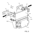
- zeigt eine perspektivische Ansicht der Haltevorrichtung der
Figur 2 mit zusätzlich gelösten Rast- oder Schnappelementen - Figur 4
- zeigt eine perspektivische Ansicht der Haltevorrichtung der
Figur 3 während eines Schwenkvorgangs in einen geöffneten Zustand nach oben, - Figur 5
- zeigt eine perspektivische Ansicht der Haltevorrichtung der
Figur 4 in hochgeklapptem, mittels den Rast- oder Schnappelementen fixiertemn Zustand, - Figur 6
- zeigt eine Seitenansicht der Haltevorrichtung der
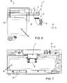
Figuren 1 bis 5 montiert an einen Kraftfahrzeugbug, - Figur 7
- zeigt eine Vorderansicht der Haltevorrichtung der
Figur 6 , - Figur 8
- zeigt eine Seitenansicht der Haltevorrichtung der
Figur 6 in hochgeklapptem Zustand und - Figur 9
- zeigt eine Vorderansicht der Haltevorrichtung der
Figur 6 in hochgeklapptem Zustand. -
Figur 1 zeigt eine perspektivische Ansicht einer Haltevorrichtung 1 gemäß einer Ausführungsform der Erfindung, währendFigur 6 eine Seitenansicht der Haltevorrichtung 1 montiert an einen Kraftfahrzeugbug B zeigt. Nachfolgend wird die Haltevorrichtung 1 zunächst unter Bezugnahme auf dieFiguren 1 und6 beschrieben. Das Kraftfahrzeug ist vorzugsweise ein Nutzfahrzeug, z.B. ein Lastkraftwagen oder ein Omnibus. - Die Haltevorrichtung 1 umfasst einen Tragabschnitt 2, der aus zwei Längsträgern (z.B. Rechteckhohlprofile) gebildet wird und zur Montage an das Kraftfahrzeug dient. Die Haltevorrichtung 1 umfasst zudem einen Halteabschnitt 3, der an dem Tragabschnitt 2 montiert ist und zum Halten eines Funktionselements S dient. Das Funktionselement S ist als Radarsensor ausgeführt und Teil eines Notbrems-Assistenzsystems des Kraftfahrzeugs.
- Das Kraftfahrzeug umfasst eine Befestigungseinrichtung 10 für ein Reserverad R für das Kraftfahrzeug, wobei das Reserverad R über eine Ausgangsöffnung A aus der Befestigungseinrichtung 10 entnommen werden kann. Die Haltevorrichtung 1 ist so an dem Kraftfahrzeug montiert, dass der Halteabschnitt 3 benachbart, insbesondere vor dem Reserverad R und vor der Ausgangsöffnung A positioniert ist.
- Der Halteabschnitt 3 ist um eine Schwenkachse 4 schwenkbar an dem Tragabschnitt 2 montiert und zwar so, dass er von einem ersten Zustand (vgl. z.B.
Figuren 1 und6 ) in einen zweiten Zustand (vgl. z.B. dieFiguren 5 und8 ) gebracht werden kann. Die Haltevorrichtung 1 oder allgemein der Halteabschnitt 3 stellt somit einen klappbaren Sensorhalter dar. - Im ersten Zustand verschließt der Halteabschnitt 3 zumindest teilweise die Ausgangsöffnung A, so dass eine Entnahme des Reserverads R über die Ausgangsöffnung A nicht oder zumindest nicht problemlos möglich ist. Im ersten Zustand befindet sich das Funktionselement S in Betriebsstellung.
- Im zweiten Zustand gibt der Halteabschnitt 3 die Ausgangsöffnung A so frei, dass das Reserverad R über die Ausgangsöffnung A entnommen werden kann.
- Die Haltevorrichtung 1 umfasst ferner zwei Verbindungselemente 5, die dazu dienen, den Halteabschnitt 3 an dem Tragabschnitt 2 im ersten Zustand zu fixieren. Die Verbindungselemente 5 sind als Schraubverbindungen mit Zentrierbolzen ausgeführt.
- Die Haltevorrichtung 1 weist ferner Rast- oder Schnappelemente 6 (nachfolgend Rastelemente genannt) auf, die dazu dienen, den Halteabschnitt 3 an dem Tragabschnitt 2 einerseits im ersten Zustand und andererseits im zweiten Zustand zu fixieren. Die Rastelemente 6 sind jeweils mit einem Vorspannelement (z.B. einer Feder) versehen, das dafür sorgt, dass die Rastelemente 6 selbsttätig und somit automatisch in den Fixierzustand gebracht werden. Die Rastelemente 6 können entgegen der Vorspannwirkung der Vorspannelemente gelöst werden.
- Die Schwenkachse 4, die Verbindungselemente 5 und die Rastelemente 6 sind in Längsrichtung L der Haltevorrichtung 1 voneinander beabstandet und zwar so, dass die Schwenkachse 4 zwischen den Verbindungselementen 5 einerseits und den Rastelementen 6 andererseits verläuft.
- Der Halteabschnitt 3 ist in drei Teilbereiche unterteilt, nämlich einen ersten oberen Teilbereich 3.1, einen zweiten unteren Teilbereich 3.2 und einen dritten Teilbereich 3.3. Der erste Teilbereich 3.1 ist schwenkbar an den Tragabschnitt 2 montiert. Der zweite Teilbereich 3.2 ist an den ersten Teilbereich 3.1 montiert, während der dritte Teilbereich 3.3 an den zweiten Teilbereich 3.2 montiert ist und das Funktionselement S trägt. Der erste Teilbereich 3.1 und der zweite Teilbereich 3.2 sind über eine Langlochkonstruktion 7.1 miteinander verbunden. Die Langlochkonstruktion 7.1 ermöglicht, dass die Position des zweiten Teilbereichs 3.2 in Längsrichtung L der Haltevorrichtung 1 relativ zum ersten Teilbereich 3.1 einstellbar ist. Der zweite Teilbereich 3.2 und der dritte Teilbereich 3.3 sind über eine Langlochkonstruktion 7.2 miteinander verbunden. Die Langlochkonstruktion 7.2 ermöglicht, dass die Position des dritten Teilbereichs 3.3 in Höhenrichtung H der Haltevorrichtung 1 relativ zu dem zweiten Teilbereich 3.2 einstellbar ist.
- Der Tragabschnitt 2 umfasst eine Langlochkonstruktion 7.3 zur Montage an das Kraftfahrzeug. Die Langlochkonstruktion 7.3 ermöglicht, dass die Haltevorrichtung 1 in Querrichtung Q der Haltevorrichtung 1 einstellbar ist.
- Die Langlochkonstruktionen 7.1, 7.2 und 7.3 gewährleisten, dass das Funktionselement S in allen drei Raumrichtungen justiert und somit exakt positioniert werden kann.
- Die
Figuren 2 bis 5 verdeutlichen, wie die Haltevorrichtung 1 von dem ersten Zustand, in dem der Halteabschnitt 2 die Ausgangsöffnung A zumindest teilweise verschließt und sich das Funktionselement S in Betriebsstellung befindet, in den zweiten Zustand gebracht werden kann, in dem der Halteabschnitt 3 die Ausgangsöffnung A so freigibt, dass das Reserverad R entnommen werden kann. - Um den Halteabschnitt in den zweiten Zustand zu bringen, werden zunächst gemäß
Figur 2 die zwei Verbindungselemente 5 in Querrichtung Q der Haltevorrichtung 1 nach außen gelöst. Der Halteabschnitt 3 bleibt mittels der Rastelemente 6 dennoch im ersten Zustand fixiert. Selbst wenn sich z.B. während der Fahrt des Kraftfahrzeugs die zwei Verbindungselemente 5 unbeabsichtigt lösen sollten, sorgen die Rastelemente 6 dafür, dass das Funktionselement S zumindest im Wesentlichen korrekt positioniert bleibt. - Gemäß
Figur 3 werden nun zusätzlich die Rastelemente 6 in Querrichtung Q der Haltevorrichtung 1 nach außen entgegen der Vorspannwirkung der Vorspannelemente gelöst. Nun befindet sich der Halteabschnitt 3 in einem verschwenkbaren Zustand. - Gemäß
Figur 4 kann nun der Halteabschnitt 3 um die Schwenkachse 4 nach oben geschwenkt werden, solange bis die Rastelemente 6 automatisch in den Fixierzustand gelangen. - In
Figur 5 befindet sich der Halteabschnitt 3 im hochgeklappten zweiten Zustand. Die Rastelemente 6 dienen dazu, den Halteabschnitt 3 im zweiten Zustand zu fixieren (vgl. durch den Kreis hervorgehobenes Detail inFigur 5 ). -
Figur 6 zeigt eine Seitenansicht eines Kraftfahrzeugbugs B mit montierter Haltevorrichtung 1, währendFigur 7 eine dazugehörige Vorderansicht zeigt. Wie schon zuvor erwähnt, umfasst der Kraftfahrzeugbug B die Befestigungseinrichtung 10 für das Reserverad R, das über die Ausgangsöffnung A entnommen werden kann. - Die
Figuren 6 und 7 zeigen den Halteabschnitt 3 im ersten Zustand, in dem die Ausgangsöffnung A zumindest teilweise durch den Halteabschnitt 3 verschlossen wird. In dem in denFiguren 6 und 7 gezeigten Zustand kann das Reserverad R nicht oder zumindest nicht problemlos über die Ausgangsöffnung A aus der Befestigungseinrichtung 10 entnommen werden.Figur 7 ist zu entnehmen, dass das Funktionselement S in Querrichtung Q des Kraftfahrzeugs mittig am Kraftfahrzeugbug B positioniert ist. -
Figur 8 zeigt eine Seitenansicht des Kraftfahrzeugbugs B mit montierter Haltevorrichtung 1, währendFigur 9 eine dazugehörige Vorderansicht zeigt. - Die
Figuren 8 und 9 zeigen den Halteabschnitt 3 in hochgeklapptem zweiten Zustand. In dem in denFiguren 8 und 9 gezeigten Zustand kann das Reserverad R über die Ausgangsöffnung A aus der Befestigungseinrichtung 10 zweckmäßig transversal entnommen werden, was durch den Pfeil inFigur 8 schematisch angedeutet ist. - Die Erfindung ist nicht auf die oben beschriebenen bevorzugten Ausführungsformen beschränkt. Vielmehr ist eine Vielzahl von Varianten und Abwandlungen möglich, die ebenfalls von dem Erfindungsgedanken Gebrauch machen und deshalb in den Schutzbereich fallen. Darüber hinaus beansprucht die Erfindung auch Schutz für den Gegenstand und die Merkmale der Unteransprüche unabhängig von den in Bezug genommenen Merkmalen und Ansprüchen.
Claims (15)
- Haltevorrichtung (1) zur Anbringung an ein Kraftfahrzeug, vorzugsweise einen Kraftfahrzeugbug (B): mit- einem Tragabschnitt (2) zur Montage an das Kraftfahrzeug, wobei der Tragabschnitt (2) vorzugsweise durch zumindest zwei Längsträger gebildet wird, und- einem Halteabschnitt (3) zum Halten eines Funktionselements (S), insbesondere einer Sensoreinrichtung, und zum Positionieren benachbart zu einer Ausgangsöffnung (A) für eine Befestigungseinrichtung (10) für ein Reserverad (R) für das Kraftfahrzeug, wobei der Halteabschnitt (3) um eine Schwenkachse (4) schwenkbar ist, von einem ersten Zustand, in dem er die Ausgangsöffnung (A) zumindest teilweise verschließt, in einen zweiten Zustand, in dem er die Ausgangsöffnung (A) so freigibt, dass das Reserverad (R) entnommen werden kann.
- Haltevorrichtung (1) nach Anspruch 1, wobei der Halteabschnitt (3) schwenkbar an dem Tragabschnitt (2) montiert ist.
- Haltevorrichtung (1) nach Anspruch 1 oder 2, mit zumindest einem Verbindungselement (5), das dazu dient, den Halteabschnitt (3) an dem Tragabschnitt (2) im ersten Zustand lösbar zu fixieren.
- Haltevorrichtung (1) nach Anspruch 3, wobei das Verbindungselement (5) als Schraubverbindung mit Zentrierbolzen ausgeführt ist.
- Haltevorrichtung (1) nach einem der vorhergehenden Ansprüche, mit zumindest einem Schnapp- oder Rastelement (6), das dazu dient, den Halteabschnitt (3) an dem Tragabschnitt (2) im ersten Zustand und/oder im zweiten Zustand lösbar zu fixieren.
- Haltevorrichtung (1) nach Anspruch 5, wobei das Rast- oder Schnappelement (6) ein Vorspannelement aufweist, mittels dem es automatisch in einen Fixierzustand gebracht wird.
- Haltevorrichtung (1) nach einem der vorhergehenden Ansprüche, wobei zumindest zwei der folgenden Teile in Längsrichtung (L) der Haltevorrichtung (1) von einander beabstandet sind:- die Schwenkachse (4),- das Verbindungselement (5),- das Schnapp- oder Rastelement (6).
- Haltevorrichtung (1) nach einem der vorhergehenden Ansprüche, wobei die Schwenkachse (4) in Längsrichtung (L) der Haltevorrichtung (1) zwischen dem Verbindungselement (5) und dem Schnapp- oder Rastelement (6) verläuft.
- Haltevorrichtung (1) nach einem der vorhergehenden Ansprüche, wobei der Halteabschnitt (3) in verschiedene Teilbereiche (3.1, 3.2) unterteilt ist und einen an dem Tragabschnitt (2) montierten ersten Teilbereich (3.1) und einen zweiten Teilbereich (3.2) aufweist, wobei die Position des zweiten Teilbereichs (3.2) relativ zum ersten Teilbereich (3.1) einstellbar ist, vorzugsweise über eine Langlochkonstruktion (7.1).
- Haltevorrichtung (1) nach Anspruch 9, wobei der Halteabschnitt (3) einen dritten Teilbereich (3.3) aufweist, wobei die Position des dritten Teilbereichs (3.3) relativ zum ersten Teilbereich (3.1) und/oder zweiten Teilbereich (3.2) einstellbar ist, vorzugsweise über eine Langlochkonstruktion (7.2).
- Haltevorrichtung (1) nach einem der vorhergehenden Ansprüche, wobei der Tragabschnitt (2) mittels einer Langlochkonstruktion (7.3) zur Montage an das Kraftfahrzeug ausgeführt ist.
- Haltevorrichtung (1) nach einem der vorhergehenden Ansprüche, wobei die Sensoreinrichtung eine Radarsensoreinrichtung zur Früherkennung eines Hindernisses und/oder für ein Notbrems-Assistenzsystem des Kraftfahrzeugs ist.
- Kraftfahrzeug, vorzugsweise Nutzfahrzeug: mit- einer Befestigungseinrichtung (10) für ein Reserverad (R) für das Kraftfahrzeug, wobei das Reserverad (R) über eine Ausgangsöffnung (A) aus der Befestigungseinrichtung (10) entnommen werden kann, und- einer am Kraftfahrzeug, vorzugsweise am Kraftfahrzeugbug (B), angeordneten Haltevorrichtung (1) mit:- einem Tragabschnitt (2) zur Montage an das Kraftfahrzeug und- einem Halteabschnitt (3) zum Halten eines Funktionselements (S), insbesondere einer Sensoreinrichtung, wobei der Halteabschnitt (3) um eine Schwenkachse (4) schwenkbar ist, von einem ersten Zustand, in dem er die Ausgangsöffnung (A) zumindest teilweise verschließt, in einen zweiten Zustand, in dem er die Ausgangsöffnung (A) so freigibt, dass das Reserverad (R) entnommen werden kann.
- Kraftfahrzeug nach Anspruch 13, wobei das Funktionselement (S) in Querrichtung (Q) des Kraftfahrzeugs mittig positioniert ist.
- Kraftfahrzeug nach Anspruch 13 oder 14, mit einer Haltevorrichtung (1) nach einem der Ansprüche 1 bis 12.
Applications Claiming Priority (1)
| Application Number | Priority Date | Filing Date | Title |
|---|---|---|---|
| DE102013005833.3A DE102013005833A1 (de) | 2013-04-04 | 2013-04-04 | Haltevorrichtung zur Anbringung an ein Kraftfahrzeug |
Publications (2)
| Publication Number | Publication Date |
|---|---|
| EP2786904A1 true EP2786904A1 (de) | 2014-10-08 |
| EP2786904B1 EP2786904B1 (de) | 2017-03-15 |
Family
ID=50030045
Family Applications (1)
| Application Number | Title | Priority Date | Filing Date |
|---|---|---|---|
| EP14000344.3A Active EP2786904B1 (de) | 2013-04-04 | 2014-01-30 | Haltevorrichtung zur anbringung an ein kraftfahrzeug |
Country Status (5)
| Country | Link |
|---|---|
| EP (1) | EP2786904B1 (de) |
| CN (1) | CN104097581B (de) |
| BR (1) | BR102014003749B1 (de) |
| DE (1) | DE102013005833A1 (de) |
| RU (1) | RU2648518C2 (de) |
Cited By (5)
| Publication number | Priority date | Publication date | Assignee | Title |
|---|---|---|---|---|
| EP3168644A1 (de) * | 2015-11-16 | 2017-05-17 | Valeo Schalter und Sensoren GmbH | Vorrichtung zur befestigung eines optischen sensors an einem kraftfahrzeug mit federelement, sensoranordnung sowie kraftfahrzeug |
| EP3168643A1 (de) * | 2015-11-16 | 2017-05-17 | Valeo Schalter und Sensoren GmbH | Vorrichtung zur befestigung eines optischen sensors an einem kraftfahrzeug mit justageeinrichtung, sensoranordnung sowie kraftfahrzeug |
| WO2017200739A1 (en) * | 2016-05-18 | 2017-11-23 | Illinois Tool Works Inc. | System for mounting radars on vehicles |
| CN110053565A (zh) * | 2018-01-18 | 2019-07-26 | 本田技研工业株式会社 | 车辆的外界传感器单元 |
| CN111867890A (zh) * | 2018-03-16 | 2020-10-30 | 雷诺股份公司 | 用于机动车辆的检测元件的支撑装置以及用于安装支撑装置的方法 |
Families Citing this family (2)
| Publication number | Priority date | Publication date | Assignee | Title |
|---|---|---|---|---|
| DE102019113492B4 (de) * | 2019-05-21 | 2021-11-11 | Dr. Ing. H.C. F. Porsche Aktiengesellschaft | Laserscanneranordnung |
| CN111796254B (zh) * | 2020-06-04 | 2024-08-06 | 一汽奔腾轿车有限公司 | 一种激光雷达安装紧固支架装置 |
Citations (5)
| Publication number | Priority date | Publication date | Assignee | Title |
|---|---|---|---|---|
| FR2380176A1 (fr) * | 1977-02-11 | 1978-09-08 | Kaessbohrer Fahrzeug Karl | Vehicule equipe d'un pare-chocs amovible |
| US4360228A (en) * | 1980-11-28 | 1982-11-23 | Rasmussen Eldon S | Bumper apparatus |
| US4896910A (en) * | 1988-09-30 | 1990-01-30 | Carter Bernie R | Combination bumper and tire storage compartment |
| WO2007074643A1 (ja) * | 2005-12-28 | 2007-07-05 | Kyokuto Kaihatsu Kogyo Co., Ltd. | 運搬車両及び運搬車両のバンパー装置 |
| US20100026019A1 (en) * | 2009-10-09 | 2010-02-04 | MMC Manufacturing, Inc. | Bumper mounting assemblies and vehicles incorporating same |
Family Cites Families (5)
| Publication number | Priority date | Publication date | Assignee | Title |
|---|---|---|---|---|
| FR2317152A1 (fr) * | 1975-07-07 | 1977-02-04 | Peugeot | Dispositif de rangement d'une roue de secours sur un vehicule automobile |
| DE10247595B4 (de) * | 2002-10-11 | 2007-05-24 | Intedis Gmbh & Co. Kg | Einbauteil für ein Kraftfahrzeug und Verfahren zur Montage eines Kraftfahrzeug-Bordnetzes |
| US6880875B2 (en) * | 2003-09-16 | 2005-04-19 | Honda Motor Company, Ltd. | Cargo protecting system for a pickup truck |
| FR2883832B1 (fr) * | 2005-03-31 | 2007-05-25 | Peugeot Citroen Automobiles Sa | Systeme de fixation d'une roue de secours d'un vehicule |
| US7900989B2 (en) * | 2008-01-08 | 2011-03-08 | Honda Motor Co., Ltd. | System for storing a spare tire |
-
2013
- 2013-04-04 DE DE102013005833.3A patent/DE102013005833A1/de not_active Withdrawn
-
2014
- 2014-01-30 EP EP14000344.3A patent/EP2786904B1/de active Active
- 2014-02-18 BR BR102014003749-7A patent/BR102014003749B1/pt not_active IP Right Cessation
- 2014-03-25 RU RU2014111450A patent/RU2648518C2/ru active
- 2014-04-04 CN CN201410134875.0A patent/CN104097581B/zh active Active
Patent Citations (5)
| Publication number | Priority date | Publication date | Assignee | Title |
|---|---|---|---|---|
| FR2380176A1 (fr) * | 1977-02-11 | 1978-09-08 | Kaessbohrer Fahrzeug Karl | Vehicule equipe d'un pare-chocs amovible |
| US4360228A (en) * | 1980-11-28 | 1982-11-23 | Rasmussen Eldon S | Bumper apparatus |
| US4896910A (en) * | 1988-09-30 | 1990-01-30 | Carter Bernie R | Combination bumper and tire storage compartment |
| WO2007074643A1 (ja) * | 2005-12-28 | 2007-07-05 | Kyokuto Kaihatsu Kogyo Co., Ltd. | 運搬車両及び運搬車両のバンパー装置 |
| US20100026019A1 (en) * | 2009-10-09 | 2010-02-04 | MMC Manufacturing, Inc. | Bumper mounting assemblies and vehicles incorporating same |
Cited By (8)
| Publication number | Priority date | Publication date | Assignee | Title |
|---|---|---|---|---|
| EP3168644A1 (de) * | 2015-11-16 | 2017-05-17 | Valeo Schalter und Sensoren GmbH | Vorrichtung zur befestigung eines optischen sensors an einem kraftfahrzeug mit federelement, sensoranordnung sowie kraftfahrzeug |
| EP3168643A1 (de) * | 2015-11-16 | 2017-05-17 | Valeo Schalter und Sensoren GmbH | Vorrichtung zur befestigung eines optischen sensors an einem kraftfahrzeug mit justageeinrichtung, sensoranordnung sowie kraftfahrzeug |
| WO2017200739A1 (en) * | 2016-05-18 | 2017-11-23 | Illinois Tool Works Inc. | System for mounting radars on vehicles |
| CN110053565A (zh) * | 2018-01-18 | 2019-07-26 | 本田技研工业株式会社 | 车辆的外界传感器单元 |
| CN110053565B (zh) * | 2018-01-18 | 2022-07-26 | 本田技研工业株式会社 | 车辆的外界传感器单元 |
| US11506779B2 (en) | 2018-01-18 | 2022-11-22 | Honda Motor Co., Ltd. | Vehicle outside sensor unit |
| CN111867890A (zh) * | 2018-03-16 | 2020-10-30 | 雷诺股份公司 | 用于机动车辆的检测元件的支撑装置以及用于安装支撑装置的方法 |
| CN111867890B (zh) * | 2018-03-16 | 2024-06-11 | 雷诺股份公司 | 用于机动车辆的检测元件的支撑装置以及用于安装支撑装置的方法 |
Also Published As
| Publication number | Publication date |
|---|---|
| CN104097581B (zh) | 2018-09-18 |
| DE102013005833A1 (de) | 2014-10-09 |
| RU2648518C2 (ru) | 2018-03-26 |
| BR102014003749A2 (pt) | 2015-12-08 |
| RU2014111450A (ru) | 2015-09-27 |
| EP2786904B1 (de) | 2017-03-15 |
| CN104097581A (zh) | 2014-10-15 |
| BR102014003749B1 (pt) | 2021-11-30 |
Similar Documents
| Publication | Publication Date | Title |
|---|---|---|
| EP2786904B1 (de) | Haltevorrichtung zur anbringung an ein kraftfahrzeug | |
| DE102014104920B4 (de) | Karosseriestruktur mit Dach-Reling | |
| DE10062686B4 (de) | Klimaanlage für ein Fahrzeug, insbesondere für einen Omnibus | |
| DE102015002055A1 (de) | Hintere Struktur eines Fahrzeuges und Verfahren zum Führen und Ableiten von Wasser von einem hinteren Abschnitt eines Fahrzeugkörpers | |
| DE102014005023B4 (de) | Längslenker sowie Achseinbindung mit einem derartigen Längslenker und Fahrzeug mit einer derartigen Achseinbindung | |
| DE102017121385A1 (de) | Blendenträger und Schubkasten | |
| DE102014103823A1 (de) | Verhakungskonzept für einen zweiteiligen Spoiler oder Flügel | |
| DE102005048289B4 (de) | Innenausbaumodul für Deckenbereiche von Fahrzeugen, insbesondere von Schienenfahrzeugen für den Personenverkehr | |
| DE102019104251A1 (de) | Halterstruktur für elektronische Bordvorrichtungen | |
| EP1610989A1 (de) | Scheibenwischvorrichtung | |
| WO2021069726A1 (de) | Vorrichtung zur befestigung einer optischen einrichtung | |
| DE102007019935A1 (de) | Befestigungsanordnung mit einem Stoßfänger und einem Kotflügel für ein Kraftfahrzeug | |
| DE102004019188B4 (de) | Haltevorrichtung zur Aufnahme eines mobilen Endgerätes/Bildschirmes | |
| DE102020128033B4 (de) | Stützteilanordnung, Montagebaukasten und Montageverfahren | |
| EP3616967B1 (de) | Fahrzeugbedienvorrichtung sowie verfahren zum ändern des anzeigewinkels einer bedien- und anzeigeeinrichtung einer derartigen fahrzeugbedienvorrichtung | |
| DE102019008257B4 (de) | Modulare Halterungsvorrichtung zum Montieren eines Gegenstands an einem Fahrzeug, Halteranordnung und Fahrzeug umfassend solch eine Halteranordnung | |
| DE4314415C2 (de) | Schwenkvorrichtung | |
| EP3453236B1 (de) | Anbauplatteneinheit | |
| DE102014115627A1 (de) | Gitterstruktur | |
| DE102014218605B4 (de) | Vorrichtung zur Befestigung einer Hinterachse an einem karosseriebaufesten Querträger eines Kraftfahrzeugs und Anordnung einer solchen Vorrichtung in einem Kraftfahrzeug | |
| DE69404717T2 (de) | Montage eines Handschuhkastens eines Kraftfahrzeugs | |
| DE102014005731A1 (de) | Aggregateraumabdeckung für einen Kraftwagen | |
| DE102013103530A1 (de) | Montagehilfsvorrichtung | |
| DE102018120652A1 (de) | Fahrzeugdachstruktur | |
| EP2700569A2 (de) | Anordnung einer Anbauplatten-Abdeckung an einer Frontanbauplatte eines Fahrzeugs, insbesondere eines Nutzfahrzeugs |
Legal Events
| Date | Code | Title | Description |
|---|---|---|---|
| PUAI | Public reference made under article 153(3) epc to a published international application that has entered the european phase |
Free format text: ORIGINAL CODE: 0009012 |
|
| 17P | Request for examination filed |
Effective date: 20140526 |
|
| AK | Designated contracting states |
Kind code of ref document: A1 Designated state(s): AL AT BE BG CH CY CZ DE DK EE ES FI FR GB GR HR HU IE IS IT LI LT LU LV MC MK MT NL NO PL PT RO RS SE SI SK SM TR |
|
| AX | Request for extension of the european patent |
Extension state: BA ME |
|
| 17Q | First examination report despatched |
Effective date: 20150528 |
|
| GRAP | Despatch of communication of intention to grant a patent |
Free format text: ORIGINAL CODE: EPIDOSNIGR1 |
|
| INTG | Intention to grant announced |
Effective date: 20161010 |
|
| GRAS | Grant fee paid |
Free format text: ORIGINAL CODE: EPIDOSNIGR3 |
|
| STAA | Information on the status of an ep patent application or granted ep patent |
Free format text: STATUS: GRANT OF PATENT IS INTENDED |
|
| GRAA | (expected) grant |
Free format text: ORIGINAL CODE: 0009210 |
|
| STAA | Information on the status of an ep patent application or granted ep patent |
Free format text: STATUS: THE PATENT HAS BEEN GRANTED |
|
| AK | Designated contracting states |
Kind code of ref document: B1 Designated state(s): AL AT BE BG CH CY CZ DE DK EE ES FI FR GB GR HR HU IE IS IT LI LT LU LV MC MK MT NL NO PL PT RO RS SE SI SK SM TR |
|
| REG | Reference to a national code |
Ref country code: CH Ref legal event code: EP Ref country code: GB Ref legal event code: FG4D Free format text: NOT ENGLISH |
|
| REG | Reference to a national code |
Ref country code: IE Ref legal event code: FG4D Free format text: LANGUAGE OF EP DOCUMENT: GERMAN |
|
| REG | Reference to a national code |
Ref country code: AT Ref legal event code: REF Ref document number: 875178 Country of ref document: AT Kind code of ref document: T Effective date: 20170415 |
|
| REG | Reference to a national code |
Ref country code: NL Ref legal event code: FP |
|
| REG | Reference to a national code |
Ref country code: DE Ref legal event code: R096 Ref document number: 502014002961 Country of ref document: DE |
|
| REG | Reference to a national code |
Ref country code: SE Ref legal event code: TRGR |
|
| REG | Reference to a national code |
Ref country code: LT Ref legal event code: MG4D |
|
| PG25 | Lapsed in a contracting state [announced via postgrant information from national office to epo] |
Ref country code: NO Free format text: LAPSE BECAUSE OF FAILURE TO SUBMIT A TRANSLATION OF THE DESCRIPTION OR TO PAY THE FEE WITHIN THE PRESCRIBED TIME-LIMIT Effective date: 20170615 Ref country code: FI Free format text: LAPSE BECAUSE OF FAILURE TO SUBMIT A TRANSLATION OF THE DESCRIPTION OR TO PAY THE FEE WITHIN THE PRESCRIBED TIME-LIMIT Effective date: 20170315 Ref country code: HR Free format text: LAPSE BECAUSE OF FAILURE TO SUBMIT A TRANSLATION OF THE DESCRIPTION OR TO PAY THE FEE WITHIN THE PRESCRIBED TIME-LIMIT Effective date: 20170315 Ref country code: LT Free format text: LAPSE BECAUSE OF FAILURE TO SUBMIT A TRANSLATION OF THE DESCRIPTION OR TO PAY THE FEE WITHIN THE PRESCRIBED TIME-LIMIT Effective date: 20170315 Ref country code: GR Free format text: LAPSE BECAUSE OF FAILURE TO SUBMIT A TRANSLATION OF THE DESCRIPTION OR TO PAY THE FEE WITHIN THE PRESCRIBED TIME-LIMIT Effective date: 20170616 |
|
| PG25 | Lapsed in a contracting state [announced via postgrant information from national office to epo] |
Ref country code: BG Free format text: LAPSE BECAUSE OF FAILURE TO SUBMIT A TRANSLATION OF THE DESCRIPTION OR TO PAY THE FEE WITHIN THE PRESCRIBED TIME-LIMIT Effective date: 20170615 Ref country code: LV Free format text: LAPSE BECAUSE OF FAILURE TO SUBMIT A TRANSLATION OF THE DESCRIPTION OR TO PAY THE FEE WITHIN THE PRESCRIBED TIME-LIMIT Effective date: 20170315 Ref country code: RS Free format text: LAPSE BECAUSE OF FAILURE TO SUBMIT A TRANSLATION OF THE DESCRIPTION OR TO PAY THE FEE WITHIN THE PRESCRIBED TIME-LIMIT Effective date: 20170315 |
|
| PG25 | Lapsed in a contracting state [announced via postgrant information from national office to epo] |
Ref country code: SK Free format text: LAPSE BECAUSE OF FAILURE TO SUBMIT A TRANSLATION OF THE DESCRIPTION OR TO PAY THE FEE WITHIN THE PRESCRIBED TIME-LIMIT Effective date: 20170315 Ref country code: RO Free format text: LAPSE BECAUSE OF FAILURE TO SUBMIT A TRANSLATION OF THE DESCRIPTION OR TO PAY THE FEE WITHIN THE PRESCRIBED TIME-LIMIT Effective date: 20170315 Ref country code: EE Free format text: LAPSE BECAUSE OF FAILURE TO SUBMIT A TRANSLATION OF THE DESCRIPTION OR TO PAY THE FEE WITHIN THE PRESCRIBED TIME-LIMIT Effective date: 20170315 Ref country code: CZ Free format text: LAPSE BECAUSE OF FAILURE TO SUBMIT A TRANSLATION OF THE DESCRIPTION OR TO PAY THE FEE WITHIN THE PRESCRIBED TIME-LIMIT Effective date: 20170315 Ref country code: ES Free format text: LAPSE BECAUSE OF FAILURE TO SUBMIT A TRANSLATION OF THE DESCRIPTION OR TO PAY THE FEE WITHIN THE PRESCRIBED TIME-LIMIT Effective date: 20170315 |
|
| PG25 | Lapsed in a contracting state [announced via postgrant information from national office to epo] |
Ref country code: SM Free format text: LAPSE BECAUSE OF FAILURE TO SUBMIT A TRANSLATION OF THE DESCRIPTION OR TO PAY THE FEE WITHIN THE PRESCRIBED TIME-LIMIT Effective date: 20170315 Ref country code: PL Free format text: LAPSE BECAUSE OF FAILURE TO SUBMIT A TRANSLATION OF THE DESCRIPTION OR TO PAY THE FEE WITHIN THE PRESCRIBED TIME-LIMIT Effective date: 20170315 Ref country code: PT Free format text: LAPSE BECAUSE OF FAILURE TO SUBMIT A TRANSLATION OF THE DESCRIPTION OR TO PAY THE FEE WITHIN THE PRESCRIBED TIME-LIMIT Effective date: 20170717 Ref country code: IS Free format text: LAPSE BECAUSE OF FAILURE TO SUBMIT A TRANSLATION OF THE DESCRIPTION OR TO PAY THE FEE WITHIN THE PRESCRIBED TIME-LIMIT Effective date: 20170715 |
|
| REG | Reference to a national code |
Ref country code: DE Ref legal event code: R097 Ref document number: 502014002961 Country of ref document: DE |
|
| PLBE | No opposition filed within time limit |
Free format text: ORIGINAL CODE: 0009261 |
|
| STAA | Information on the status of an ep patent application or granted ep patent |
Free format text: STATUS: NO OPPOSITION FILED WITHIN TIME LIMIT |
|
| REG | Reference to a national code |
Ref country code: FR Ref legal event code: PLFP Year of fee payment: 5 |
|
| PG25 | Lapsed in a contracting state [announced via postgrant information from national office to epo] |
Ref country code: DK Free format text: LAPSE BECAUSE OF FAILURE TO SUBMIT A TRANSLATION OF THE DESCRIPTION OR TO PAY THE FEE WITHIN THE PRESCRIBED TIME-LIMIT Effective date: 20170315 |
|
| 26N | No opposition filed |
Effective date: 20171218 |
|
| PG25 | Lapsed in a contracting state [announced via postgrant information from national office to epo] |
Ref country code: SI Free format text: LAPSE BECAUSE OF FAILURE TO SUBMIT A TRANSLATION OF THE DESCRIPTION OR TO PAY THE FEE WITHIN THE PRESCRIBED TIME-LIMIT Effective date: 20170315 |
|
| REG | Reference to a national code |
Ref country code: CH Ref legal event code: PL |
|
| GBPC | Gb: european patent ceased through non-payment of renewal fee |
Effective date: 20180130 |
|
| PG25 | Lapsed in a contracting state [announced via postgrant information from national office to epo] |
Ref country code: MT Free format text: LAPSE BECAUSE OF FAILURE TO SUBMIT A TRANSLATION OF THE DESCRIPTION OR TO PAY THE FEE WITHIN THE PRESCRIBED TIME-LIMIT Effective date: 20170315 |
|
| PG25 | Lapsed in a contracting state [announced via postgrant information from national office to epo] |
Ref country code: LU Free format text: LAPSE BECAUSE OF NON-PAYMENT OF DUE FEES Effective date: 20180130 |
|
| REG | Reference to a national code |
Ref country code: IE Ref legal event code: MM4A |
|
| REG | Reference to a national code |
Ref country code: BE Ref legal event code: MM Effective date: 20180131 |
|
| PG25 | Lapsed in a contracting state [announced via postgrant information from national office to epo] |
Ref country code: LI Free format text: LAPSE BECAUSE OF NON-PAYMENT OF DUE FEES Effective date: 20180131 Ref country code: CH Free format text: LAPSE BECAUSE OF NON-PAYMENT OF DUE FEES Effective date: 20180131 Ref country code: BE Free format text: LAPSE BECAUSE OF NON-PAYMENT OF DUE FEES Effective date: 20180131 Ref country code: GB Free format text: LAPSE BECAUSE OF NON-PAYMENT OF DUE FEES Effective date: 20180130 |
|
| PG25 | Lapsed in a contracting state [announced via postgrant information from national office to epo] |
Ref country code: IE Free format text: LAPSE BECAUSE OF NON-PAYMENT OF DUE FEES Effective date: 20180130 |
|
| PG25 | Lapsed in a contracting state [announced via postgrant information from national office to epo] |
Ref country code: MC Free format text: LAPSE BECAUSE OF FAILURE TO SUBMIT A TRANSLATION OF THE DESCRIPTION OR TO PAY THE FEE WITHIN THE PRESCRIBED TIME-LIMIT Effective date: 20170315 |
|
| REG | Reference to a national code |
Ref country code: DE Ref legal event code: R081 Ref document number: 502014002961 Country of ref document: DE Owner name: MAN TRUCK & BUS SE, DE Free format text: FORMER OWNER: MAN TRUCK & BUS AG, 80995 MUENCHEN, DE |
|
| REG | Reference to a national code |
Ref country code: AT Ref legal event code: MM01 Ref document number: 875178 Country of ref document: AT Kind code of ref document: T Effective date: 20190130 |
|
| PG25 | Lapsed in a contracting state [announced via postgrant information from national office to epo] |
Ref country code: TR Free format text: LAPSE BECAUSE OF FAILURE TO SUBMIT A TRANSLATION OF THE DESCRIPTION OR TO PAY THE FEE WITHIN THE PRESCRIBED TIME-LIMIT Effective date: 20170315 |
|
| PG25 | Lapsed in a contracting state [announced via postgrant information from national office to epo] |
Ref country code: AT Free format text: LAPSE BECAUSE OF NON-PAYMENT OF DUE FEES Effective date: 20190130 |
|
| PG25 | Lapsed in a contracting state [announced via postgrant information from national office to epo] |
Ref country code: HU Free format text: LAPSE BECAUSE OF FAILURE TO SUBMIT A TRANSLATION OF THE DESCRIPTION OR TO PAY THE FEE WITHIN THE PRESCRIBED TIME-LIMIT; INVALID AB INITIO Effective date: 20140130 |
|
| PG25 | Lapsed in a contracting state [announced via postgrant information from national office to epo] |
Ref country code: MK Free format text: LAPSE BECAUSE OF NON-PAYMENT OF DUE FEES Effective date: 20170315 Ref country code: CY Free format text: LAPSE BECAUSE OF FAILURE TO SUBMIT A TRANSLATION OF THE DESCRIPTION OR TO PAY THE FEE WITHIN THE PRESCRIBED TIME-LIMIT Effective date: 20170315 |
|
| PG25 | Lapsed in a contracting state [announced via postgrant information from national office to epo] |
Ref country code: AL Free format text: LAPSE BECAUSE OF FAILURE TO SUBMIT A TRANSLATION OF THE DESCRIPTION OR TO PAY THE FEE WITHIN THE PRESCRIBED TIME-LIMIT Effective date: 20170315 |
|
| PGFP | Annual fee paid to national office [announced via postgrant information from national office to epo] |
Ref country code: NL Payment date: 20250127 Year of fee payment: 12 |
|
| PGFP | Annual fee paid to national office [announced via postgrant information from national office to epo] |
Ref country code: DE Payment date: 20250129 Year of fee payment: 12 |
|
| PGFP | Annual fee paid to national office [announced via postgrant information from national office to epo] |
Ref country code: SE Payment date: 20250127 Year of fee payment: 12 |
|
| PGFP | Annual fee paid to national office [announced via postgrant information from national office to epo] |
Ref country code: FR Payment date: 20250127 Year of fee payment: 12 |
|
| PGFP | Annual fee paid to national office [announced via postgrant information from national office to epo] |
Ref country code: IT Payment date: 20250122 Year of fee payment: 12 |