EP2784263B1 - Rolloeinrichtung einer Schließvorrichtung eines Gebäudes - Google Patents
Rolloeinrichtung einer Schließvorrichtung eines Gebäudes Download PDFInfo
- Publication number
- EP2784263B1 EP2784263B1 EP14160406.6A EP14160406A EP2784263B1 EP 2784263 B1 EP2784263 B1 EP 2784263B1 EP 14160406 A EP14160406 A EP 14160406A EP 2784263 B1 EP2784263 B1 EP 2784263B1
- Authority
- EP
- European Patent Office
- Prior art keywords
- roller blind
- axis
- shaft
- rotation
- roller
- Prior art date
- Legal status (The legal status is an assumption and is not a legal conclusion. Google has not performed a legal analysis and makes no representation as to the accuracy of the status listed.)
- Active
Links
Images


Classifications
-
- E—FIXED CONSTRUCTIONS
- E06—DOORS, WINDOWS, SHUTTERS, OR ROLLER BLINDS IN GENERAL; LADDERS
- E06B—FIXED OR MOVABLE CLOSURES FOR OPENINGS IN BUILDINGS, VEHICLES, FENCES OR LIKE ENCLOSURES IN GENERAL, e.g. DOORS, WINDOWS, BLINDS, GATES
- E06B9/00—Screening or protective devices for wall or similar openings, with or without operating or securing mechanisms; Closures of similar construction
- E06B9/56—Operating, guiding or securing devices or arrangements for roll-type closures; Spring drums; Tape drums; Counterweighting arrangements therefor
- E06B9/68—Operating devices or mechanisms, e.g. with electric drive
- E06B9/70—Operating devices or mechanisms, e.g. with electric drive comprising an electric motor positioned outside the roller
-
- E—FIXED CONSTRUCTIONS
- E06—DOORS, WINDOWS, SHUTTERS, OR ROLLER BLINDS IN GENERAL; LADDERS
- E06B—FIXED OR MOVABLE CLOSURES FOR OPENINGS IN BUILDINGS, VEHICLES, FENCES OR LIKE ENCLOSURES IN GENERAL, e.g. DOORS, WINDOWS, BLINDS, GATES
- E06B9/00—Screening or protective devices for wall or similar openings, with or without operating or securing mechanisms; Closures of similar construction
- E06B9/24—Screens or other constructions affording protection against light, especially against sunshine; Similar screens for privacy or appearance; Slat blinds
- E06B9/40—Roller blinds
- E06B9/42—Parts or details of roller blinds, e.g. suspension devices, blind boxes
-
- E—FIXED CONSTRUCTIONS
- E06—DOORS, WINDOWS, SHUTTERS, OR ROLLER BLINDS IN GENERAL; LADDERS
- E06B—FIXED OR MOVABLE CLOSURES FOR OPENINGS IN BUILDINGS, VEHICLES, FENCES OR LIKE ENCLOSURES IN GENERAL, e.g. DOORS, WINDOWS, BLINDS, GATES
- E06B9/00—Screening or protective devices for wall or similar openings, with or without operating or securing mechanisms; Closures of similar construction
- E06B9/24—Screens or other constructions affording protection against light, especially against sunshine; Similar screens for privacy or appearance; Slat blinds
- E06B9/40—Roller blinds
- E06B9/42—Parts or details of roller blinds, e.g. suspension devices, blind boxes
- E06B9/50—Bearings specially adapted therefor
Definitions
- the invention relates to a blind device of a closing device of a building according to the preamble of claim 1.
- Such a roller blind device comprises a roller shaft which is rotatable about a roller shaft axis and a drive device which has an output shaft and is designed to adjust the roller shaft electrically via the output shaft.
- a locking device the component of which is the roller blind device
- a closing device comprises in particular a frame (also referred to as a "frame” in the case of a door) and a adjusting wing arranged thereon.
- the roller blind device serves to at least partially cover the adjusting leaf with a roller blind (a blind shade or a shutter formed by lamellae) in an extended state, so that a building opening is shaded and, if necessary, an additional protection against burglary is provided.
- a so-called tubular motor is used to drive a roller blind, as he, for example, from the DE 102 11 736 A1 is known.
- Such a tubular motor is used in the roller blind shaft and has an output shaft which extends collinearly to the roller shaft axis and engages in the roller shaft for driving the roller shaft.
- US 4,974,658 A a roller shutter system in which a roller blind between two lateral guides is adjusted by means of an electric motor, wherein the electric motor drives the roller blind shaft, on which the roller blind up or unwound.
- Object of the present invention is to provide a blind device of a closing device of a building, which allows the use of a cheap, space-efficient, reliable drive device.
- the roller blind device has a gear stage via which the output shaft is operatively connected to the roller shaft and which has a first gear wheel which is mounted so as to be rotatable about a first rotational axis parallel to the roller shaft axis and spaced from the roller shaft axis.
- the output shaft of the roller blind device carries a worm toothing, which engages with a dial wheel fixedly connected to the first gear wheel and, during operation, drives the adjusting wheel rotatably mounted about the first rotational axis.
- the first gear wheel which can be rotated about the first axis of rotation, can be provided, for example, with a second gear wheel, which is parallel to the first axis of rotation, the second axis of rotation is rotatable, engaged.
- the second gear is connected to a pinion, which engages in an internal toothing of the roller blind shaft and thus transmits an adjusting force to the roller shaft.
- first gear is made possible to make the position and orientation of an output shaft of the drive device of the roller shaft axis independently.
- the output shaft transmits an adjusting force to the first gear wheel, which engages via the second gear and the pinion with the roller shaft and thus drives the roller shaft.
- first gear with its (first) axis of rotation is parallel, but (transverse to the first axis of rotation) spaced from the roller shaft axis, the position of the output shaft can be chosen freely and in particular be made dependent on the available space conditions.
- the coupling of the output shaft of the drive device with the roller shaft then takes place via the gear stage, which provides a power transmission line between the drive device and the roller shaft.
- the output shaft of the drive device may in particular be rotatable about a third axis of rotation, wherein the third axis of rotation is at an angle to the first axis of rotation.
- the third axis of rotation can be transverse to the first axis of rotation.
- the pairing of the output shaft and the adjusting wheel in particular provides a reduction gear, so that the rotational speed of the output shaft is transmitted in a reduced manner in a reduced rotational speed of the setting wheel.
- the gear stage may, for example, provide a gear stage which translates the rotational speed of the setting wheel in a suitable manner into a rotational speed of the roller shaft. By means of the gear stage can thus be achieved in a desired manner an adjustment of the movement of the output shaft in a rotary motion of the roller shaft.
- the roller blind shaft is preferably enclosed by a roller blind box of the roller blind device.
- the drive device is in this case preferably arranged at an axial end of the roller shaft within the roller blind box and thus connects axially to the roller shaft.
- the roller shaft can advantageously be rotatably mounted on a housing of the drive device, so that via the housing of the drive device, the roller shaft is supported relative to the roller blind box.
- this may be provided on the housing, a bearing plate which carries a bearing bush in which the roller shaft is rotatably mounted.
- the drive device may have an (integrated) control electronics for controlling the operation of the drive device.
- the control electronics can for example be designed as so-called plug-in electronics, which is inserted into the housing of the drive device and, for example, also has a sensor for detecting the rotational movement of the output shaft.
- integrated drive devices which are designed as motor-gear unit with integrated control electronics, are available from the vehicle technology, for example, as window lift drives and can advantageously also for driving a roller blind in a roller blind device of a closing device of a building, such as a window or a door Building, to be used.
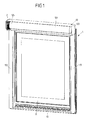
- Fig. 1 shows a closing device 1 in the form of a window of a building, which has a frame 10 and a pivotally mounted thereto pivoting wing 11 in the form of a sash.
- the sash 11 can be pivoted in a conventional manner, for example, two different pivot axes - namely a horizontal pivot axis for tilting the sash 11 and about a vertical pivot axis for opening the window sash 11 - to the frame 10, for this purpose, a locking device between the frame 10 and the window sash 11 acts, which can be adjusted to lock depending on the locking position the window sash 11 with the frame 10 to tilt its horizontal pivot axis or to pivot about its vertical pivot axis.
- the closing device 1 has a roller blind device 12 with a roller blind shaft 121 which is rotatably mounted in a roller blind box 120.
- a roller blind in the form of a roller blind or a shutter can be arranged in a manner known per se so that the roller blind can be moved along the roller blinds 122, 123 in front of the window sash 11 by rotating the roller blind shaft 121, to shade a covered by the window sash 11 building opening and the window, if necessary, in addition from the outside z. B. to protect against burglary.
- the roller blind device 12 has a drive device 2, which serves for electromotive adjustment of the roller blind shaft 121 and is then arranged axially at an axial end 125 of the roller blind shaft 121 within the roller blind box 120.
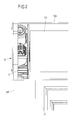
- FIG. 2 to 6 A concrete embodiment of such a drive device is in Fig. 2 to 6 shown.
- the drive device has, as is apparent from the exploded views according to Fig. 5A and 5B results in an enclosed in a housing 22 electric motor 20 having a rotatable about an axis of rotation D3 output shaft 201 (in Fig. 5A only shown schematically) drives.
- the output shaft 201 is connected via a worm toothing with a setting wheel 202 (in Fig. 5A also shown only schematically) in engagement and puts this in operation in a rotational movement about a rotation axis D1.
- the thumbwheel 202 is rotatably mounted on a bearing pin 203 about the axis of rotation D1 and is connected via an output gear 204 with a gear formed by gears 205, 206 gear stage in engagement.
- the setting wheel 202 is firmly connected to a first gear 205 which is rotatable about the same axis D1 as the thumbwheel 202.
- the first gear 205 is connected via an external toothing with a second gear 206 into engagement, which in turn is fixedly connected to a pinion 207 and engages about it in an internal toothing 212 of a neck nozzle 21.
- the attachment piece 21 is positively connected to the roller shaft 121 and engages in a corresponding, axially extending recess or bore of the roller shaft 121, so that the roller shaft 121 can be set in a rotational movement about its assigned roller shaft axis D by rotating the attachment protection.
- the output shaft 201 is, as I said, rotatable about its associated axis of rotation D3.
- the rotational axis D3 of the output shaft 201 extends here transversely to the rotational axis D1 of the setting wheel 202 and the first gear 205.
- the second gear 206 is rotatably mounted about a parallel to the rotational axis D1 of the first gear 205 axis of rotation D2, both the axis of rotation D1 of the first Gearwheel 205 and the axis of rotation D2 of the second gear 206 parallel to the roller shaft axis D, but (viewed transversely to the roller shaft axis D) are spaced from the roller shaft axis D. Both the first gear 205 and the second gear 206 are thus mounted eccentrically to the roller shaft 121.
- the output shaft 201 displaces the adjusting wheel 202 and thus the first gear 205, for example, as in Fig. 6 shown, in a rotational movement in a direction of rotation V1 about the associated axis of rotation D1.
- the second gear 206 engaged with the first gear 205 is driven in an opposite direction of rotation V2 about the rotational axis D2 associated therewith.
- roller blind shaft 121 is driven about the rotation axis D in the opposite direction of rotation V, so that a roller blind 124 is wound in a direction of movement B on the roller shaft 121.
- the attachment piece 21 and thus also the roller shaft 121 are rotatably supported by a bearing pin 210 about the rotation axis D on a bearing bush 230 of a bearing plate 23 of the drive device 2.
- the bearing pin 210 lies in a slide bushing 211, which in turn is supported in the bearing bush 230 and provides an advantageous sliding bearing of the bearing pin 210 on the bearing bush 230.
- the bearing plate 23 is connected via attachment points 233 fixed to the housing 22, which also carries the motor-gear unit with the electric motor 20 and the thumbwheel 202. Via the housing 22, the bearing plate 23 is supported on the roller blind box 120, so that via the housing 22, the roller blind shaft 121 is mounted on the roller blind box 120.
- the bearing plate 23 also has bearing openings 231, 232.
- the bearing opening 231 is penetrated by the pinion 207, which is slidably mounted on the bearing opening 231 via a sliding bushing 208 and via a fastening means 209 (see Fig. 5B ) is fixedly connected to the second gear 206, so that the pinion 207 is moved with a movement of the second gear 206 together with the second gear 206.
- a fastening means 209 see Fig. 5B
- the pinion 207 passes through an opening 221 of the housing 22.
- the bearing pin 204 passes through an opening 222 of the housing 22.
- the drive device 2 is completely enclosed in the roller blind box 120.
- the drive device 2 extends substantially flat in a plane perpendicular to the roller shaft axis D of the roller blind shaft 121 and can be arranged in this way space-saving and space efficient at the axial end 125 of the roller shaft 121, as in particular Fig. 2 is apparent.
- the storage of the roller shaft 121 takes place via the housing 22 of the drive device. 2
- the illustrated arrangement of the drive device 2 within the roller shutter box 120 in the region of the axial end 125 of the roller shaft 121 is possible in that the rotational movement of the output shaft 201, whose axis of rotation D3 extends transversely to the roller shaft axis D of the roller shaft 121, via which by the gears 205, 206 formed gear stage is transmitted to the roller shaft 121.
- the output shaft 201 in this case drives the setting wheel 202, whose axis of rotation D1 is directed perpendicularly to the axis of rotation D3 of the output shaft 201, but eccentrically, ie transversely spaced to the roller shaft axis D is arranged.
- the transverse distance between the axis of rotation D1 of the setting wheel 202 and the roller shaft axis D is bridged by the gear stage formed by the gear wheels 205, 206.
- the drive device with the rotation axis D3 of the output shaft 201 and the rotation axis D1 of the setting wheel 102 in the position independently and spatially spaced from the roller shaft axis D of the roller shaft 121 can be arranged.
- the drive device 2 can be realized in a favorable manner as a motor-gear unit, as it is known from automotive engineering, for example, from the window regulator. Such low-cost motor-gear units are reliable in operation and can be arranged in a space-saving manner within the blind box 120.
- the motor-gear unit with the electric motor 20 includes a control electronics 24, which is designed as a so-called plug-in electronics and inserted into a motor housing of the motor-gear unit.
- the control electronics 24 comprises a plug 200, via which the drive device 2 can be supplied electrically.
- an anti-pinch in the drive device 2 can be realized, as is known analogously to a window in motor vehicles.
- the anti-trap protection it can be detected, in particular when shutting down a roller blind web 124, whether there is a foreign body in the movement path of the roller blind 124, so that optionally a movement process of the roller blind 124 can be stopped.
- the closing device can in principle also be realized as the door of a building or as another closing device which is used on a building.
Landscapes
- Engineering & Computer Science (AREA)
- Structural Engineering (AREA)
- Architecture (AREA)
- Civil Engineering (AREA)
- Operating, Guiding And Securing Of Roll- Type Closing Members (AREA)
- Power-Operated Mechanisms For Wings (AREA)
Description
- Die Erfindung betrifft eine Rolloeinrichtung einer Schließvorrichtung eines Gebäudes nach dem Oberbegriff des Anspruchs 1.
- Eine derartige Rolloeinrichtung umfasst eine um eine Rollowellenachse drehbare Rollowelle und eine Antriebsvorrichtung, die eine Abtriebswelle aufweist und ausgebildet ist, über die Abtriebswelle die Rollowelle elektromotorisch zu verstellen.
- Eine Schließvorrichtung, deren Bestandteil die Rolloeinrichtung ist, kann beispielsweise als Fenster oder Tür eines Gebäudes ausgestaltet sein. Eine solche Schließvorrichtung umfasst insbesondere einen Rahmen (im Fall einer Tür auch als "Zarge" bezeichnet) und einen daran angeordneten Verstellflügel. Die Rolloeinrichtung dient dazu, mit einer Rollobahn (ein Rollobehang oder ein durch Lamellen gebildeter Rolladen) in einem ausgefahrenen Zustand den Verstellflügel zumindest teilweise abzudecken, so dass eine Gebäudeöffnung abgeschattet ist und zudem ggf. ein zusätzlicher Schutz vor Einbruch bereitgestellt wird.
- Bei herkömmlichen Rolloeinrichtungen dieser Art, wird zum Antreiben einer Rollowelle ein sogenannter Rohrmotor eingesetzt, wie er beispielsweise aus der
DE 102 11 736 A1 bekannt ist. Ein solcher Rohrmotor wird in die Rollowelle eingesetzt und weist eine Abtriebswelle auf, die sich kollinear zu der Rollowellenachse erstreckt und zum Antreiben der Rollowelle in die Rollowelle eingreift. - Aus der
EP 1 413 707 A1 ist eine Rolloeinrichtung gemäß dem Oberbegriff des Anspruchs 1 bekannt. - Weiterhin ist in der
DE 39 20 656 A1 ein Rollladensystem beschrieben, bei dem ein Rollladentrieb unter Verwendung eines an einer Rollladenwelle anzusetzenden Versetzungsgetriebes aus der Mauerwerksöffnung heraus verlagert ist. - Ferner offenbart die
US 4 974 658 A ein Rollladensystem, bei dem ein Rollo zwischen zwei seitlichen Führungen mittels eines Elektromotors verstellt wird, wobei der Elektromotor die Rollowelle antreibt, auf der das Rollo auf- bzw. abgewickelt wird. - Es besteht ein Bedürfnis nach Antriebsvorrichtungen für eine Rolloeinrichtung, die günstig herzustellen sind, einen geringen Bauraum erfordern und gleichzeitig zuverlässig in ihrem Betrieb sind.
- Aufgabe der vorliegenden Erfindung ist es, eine Rolloeinrichtung einer Schließvorrichtung eines Gebäudes bereitzustellen, die die Verwendung einer günstigen, bauraumeffizienten, zuverlässigen Antriebsvorrichtung ermöglicht.
- Die Aufgabe wird gelöst durch einen Gegenstand mit den Merkmalen des Anspruchs 1.
- Demnach weist die Rolloeinrichtung eine Getriebestufe auf, über die die Abtriebswelle mit der Rollowelle wirkverbunden ist und die ein erstes Getrieberad aufweist, das um eine zur Rollowellenachse parallele, von der Rollowellenachse beabstandete, erste Drehachse drehbar gelagert ist. Zusätzlich trägt die Abtriebswelle der Rolloeinrichtung eine Schneckenverzahnung, die mit einem mit dem ersten Getrieberad fest verbundenen Stellrad in Eingriff steht und im Betrieb das um die erste Drehachse drehbar gelagerte Stellrad antreibt.
- Das um die erste Drehachse drehbare, erste Getrieberad kann beispielsweise mit einem zweiten Getrieberad, das um eine zur ersten Drehachse parallele, zweite Drehachse drehbar ist, in Eingriff stehen. Das zweite Getrieberad ist mit einem Ritzel verbunden, das in eine Innenverzahnung der Rollowelle eingreift und somit eine Verstellkraft auf die Rollowelle überträgt.
- Mittels der Getriebestufe und dem exzentrisch zur Rollowellenachse drehbar gelagerten ersten Getrieberad wird ermöglicht, die Lage und Ausrichtung einer Abtriebswelle der Antriebsvorrichtung von der Rollowellenachse unabhängig zu machen. Die Abtriebswelle überträgt eine Verstellkraft auf das erste Getrieberad, die über das zweite Getrieberad und das Ritzel mit der Rollowelle in Eingriff steht und somit die Rollowelle antreibt. Dadurch, dass das erste Getrieberad mit seiner (ersten) Drehachse parallel, aber (quer zur ersten Drehachse) beabstandet zur Rollowellenachse angeordnet ist, kann die Lage der Abtriebswelle frei gewählt und insbesondere von den verfügbaren Bauraumgegebenheiten abhängig gemacht werden. Die Kopplung der Abtriebswelle der Antriebsvorrichtung mit der Rollowelle erfolgt dann über die Getriebestufe, die einen Kraftübertragungsstrang zwischen der Antriebsvorrichtung und der Rollowelle bereitstellt.
- Die Abtriebswelle der Antriebsvorrichtung kann insbesondere um eine dritte Drehachse drehbar sein, wobei die dritte Drehachse unter einem Winkel zur ersten Drehachse erstreckt ist. Insbesondere kann die dritte Drehachse quer zur ersten Drehachse erstreckt sein.
- Die Paarung der Abtriebswelle und des Stellrads stellt insbesondere ein Untersetzungsgetriebe bereit, so dass die Drehgeschwindigkeit der Abtriebswelle in untersetzter Weise in eine reduzierte Drehgeschwindigkeit des Stellrads übertragen wird. Die Getriebestufe kann beispielsweise eine Übersetzungsstufe bereitstellen, die die Drehgeschwindigkeit des Stellrads in geeigneter Weise in eine Drehgeschwindigkeit der Rollowelle übersetzt. Mittels der Getriebestufe kann somit in gewünschter Weise eine Anpassung der Bewegung der Abtriebswelle in eine Drehbewegung der Rollowelle erreicht werden.
- Dadurch, dass die Abtriebswelle in anderer Lage und Ausrichtung als die Rollowellenachse angeordnet werden kann, können Antriebsvorrichtungen verwendet werden, die in günstiger Bauart beispielsweise aus der Fahrzeugtechnik verfügbar sind und sich durch eine bauraumeffiziente Bauart bei hoher Zuverlässigkeit im Betrieb auszeichnen.
- Die Rollowelle ist vorzugsweise von einem Rollokasten der Rolloeinrichtung eingefasst. Die Antriebsvorrichtung ist hierbei vorzugsweise an einem axialen Ende der Rollowelle innerhalb des Rollokastens angeordnet und schließt somit axial an die Rollowelle an. Die Rollowelle kann hierbei vorteilhafterweise drehbar an einem Gehäuse der Antriebsvorrichtung gelagert sein, so dass über das Gehäuse der Antriebsvorrichtung die Rollowelle gegenüber dem Rollokasten abgestützt ist. Beispielsweise kann hierzu an dem Gehäuse eine Lagerplatte vorgesehen sein, die eine Lagerbuchse trägt, in der die Rollowelle drehbar gelagert ist.
- In vorteilhafter Ausgestaltung kann die Antriebsvorrichtung eine (integrierte) Steuerelektronik zum Steuern des Betriebs der Antriebsvorrichtung aufweisen. Die Steuerelektronik kann beispielsweise als sogenannte Einschubelektronik, die in das Gehäuse der Antriebsvorrichtung eingeschoben ist und beispielsweise auch eine Sensorik zur Erfassung der Drehbewegung der Abtriebswelle aufweist, ausgebildet sein. Solche integrierten Antriebsvorrichtungen, die als Motor-Getriebe-Einheit mit integrierter Steuerelektronik ausgebildet sind, sind aus der Fahrzeugtechnik beispielsweise als Fensterheberantriebe verfügbar und können in vorteilhafter Weise auch zum Antreiben einer Rollowelle bei einer Rolloeinrichtung einer Schließvorrichtung eines Gebäudes, beispielsweise eines Fensters oder einer Tür eines Gebäudes, eingesetzt werden.
- Der der Erfindung zugrunde liegende Gedanke soll nachfolgend anhand der in den Figuren dargestellten Ausführungsbeispiele näher erläutert werden. Es zeigen:
- Fig. 1
- eine Ansicht einer Schließvorrichtung eines Gebäudes in Form eines Fensters mit daran angeordneter Rolloeinrichtung;
- Fig. 2
- eine Ansicht einer Antriebsvorrichtung der Rolloeinrichtung in einem Rollokasten;
- Fig. 3
- eine andere, perspektivische Ansicht der Antriebsvorrichtung;
- Fig. 4
- eine Seitenansicht auf die Antriebsvorrichtung im Rollokasten;
- Fig. 5A
- eine Explosionsansicht der Antriebsvorrichtung;
- Fig. 5B
- eine andere Explosionsansicht der Antriebsvorrichtung; und
- Fig. 6
- eine Seitenansicht der Antriebsvorrichtung im Rollokasten, darstellend die Wechselwirkung zwischen Getrieberäder der Antriebsvorrichtung und der Rollowelle.
-
Fig. 1 zeigt eine Schließvorrichtung 1 in Form eines Fensters eines Gebäudes, das einen Rahmen 10 und einen daran verschwenkbar angeordneten Schwenkflügel 11 in Form eines Fensterflügels aufweist. Der Fensterflügel 11 kann in an sich bekannter Weise beispielsweise um zwei unterschiedliche Schwenkachsen - nämlich eine horizontale Schwenkachse zum Verkippen des Fensterflügels 11 und um eine vertikale Schwenkachse zum Öffnen des Fensterflügels 11 - zum Rahmen 10 verschwenkbar sein, wobei hierzu eine Verriegelungseinrichtung zwischen dem Rahmen 10 und dem Fensterflügel 11 wirkt, die verstellt werden kann, um abhängig von der Verriegelungsstellung den Fensterflügel 11 mit dem Rahmen 10 zu verriegeln, um seine horizontale Schwenkachse zu verkippen oder um seine vertikale Schwenkachse zu verschwenken. - Die Schließvorrichtung 1 weist eine Rolloeinrichtung 12 mit einer in einem Rollokasten 120 drehbar gelaberten Rollowelle 121 auf. An der Rollowelle 121 kann in an sich bekannter Weise eine Rollobahn in Form eines Rollobehangs oder eines (aus Lamellen bestehenden) Rollladens angeordnet sein, so dass durch Verdrehen der Rollowelle 121 die Rollobahn entlang von Rolloschienen 122, 123 vor den Fensterflügel 11 bewegt werden kann, um eine durch den Fensterflügel 11 verdeckte Gebäudeöffnung abzuschatten und das Fenster gegebenenfalls zusätzlich von außen z. B. vor Einbruch zu schützen.
- Die Rolloeinrichtung 12 weist eine Antriebsvorrichtung 2 auf, die zum elektromotorischen Verstellen der Rollowelle 121 dient und axial anschließend an einem axialen Ende 125 der Rollowelle 121 innerhalb des Rollokastens 120 angeordnet ist.
- Ein konkretes Ausführungsbeispiel einer solchen Antriebsvorrichtung ist in
Fig. 2 bis 6 dargestellt. Die Antriebsvorrichtung weist, wie sich aus den Explosionsansichten gemäßFig. 5A und5B ergibt, eine in einem Gehäuse 22 eingefassten Elektromotor 20 auf, der eine um eine Drehachse D3 drehbare Abtriebswelle 201 (inFig. 5A nur schematisch dargestellt) antreibt. Die Abtriebswelle 201 steht über eine Schneckenverzahnung mit einem Stellrad 202 (inFig. 5A ebenfalls nur schematisch dargestellt) in Eingriff und versetzt dieses im Betrieb in eine Drehbewegung um eine Drehachse D1. - Das Stellrad 202 ist an einem Lagerbolzen 203 um die Drehachse D1 drehbar gelagert und steht über ein Abtriebsritzel 204 mit einer durch Getrieberäder 205, 206 gebildeten Getriebestufe in Eingriff. Über das Abtriebsritzel 204 ist das Stellrad 202 dabei fest verbunden mit einem ersten Getrieberad 205, das um dieselbe Drehachse D1 wie das Stellrad 202 drehbar ist. Das erste Getrieberad 205 steht über eine Außenverzahnung mit einem zweiten Getrieberad 206 in Eingriff, das wiederum fest mit einem Ritzel 207 verbunden ist und darüber in eine Innenverzahnung 212 eines Ansatzstutzens 21 eingreift. Der Ansatzstutzen 21 ist formschlüssig mit der Rollowelle 121 verbunden und greift in eine entsprechende, axial erstreckte Aussparung oder Bohrung der Rollowelle 121 ein, so dass durch Verdrehen des Ansatzschutzes 21 die Rollowelle 121 in eine Drehbewegung um eine ihr zugeordnete Rollowellenachse D versetzt werden kann.
- Die Abtriebswelle 201 ist, wie gesagt, um die ihr zugeordnete Drehachse D3 drehbar. Die Drehachse D3 der Abtriebswelle 201 erstreckt sich hierbei quer zur Drehachse D1 des Stellrads 202 und des ersten Getrieberads 205. Das zweite Getrieberad 206 ist um eine parallel zur Drehachse D1 des ersten Getrieberads 205 erstreckte Drehachse D2 drehbar gelagert, wobei sowohl die Drehachse D1 des ersten Getrieberads 205 als auch die Drehachse D2 des zweiten Getrieberads 206 parallel zur Rollowellenachse D verlaufen, dabei aber (in Querrichtung quer zur Rollowellenachse D betrachtet) von der Rollowellenachse D beabstandet sind. Sowohl das erste Getrieberad 205 als auch das zweite Getrieberad 206 sind somit exzentrisch zu der Rollowelle 121 gelagert.
- Im Betrieb versetzt die Abtriebswelle 201 das Stellrad 202 und damit das erste Getrieberad 205 beispielsweise, wie in
Fig. 6 dargestellt, in eine Drehbewegung in eine Drehrichtung V1 um die zugeordnete Drehachse D1. Entsprechend wird das mit dem ersten Getrieberad 205 in Eingriff stehende, zweite Getrieberad 206 in eine entgegengesetzte Drehrichtung V2 um die ihm zugeordnete Drehachse D2 angetrieben. Durch den Eingriff des mit dem zweiten Getrieberad 206 fest verbundenen Ritzels 207 in die Innenverzahnung 212 des Ansatzstutzens 21 wird der Ansatzstutzen 21 und damit auch die fest mit dem Ansatzstutzen 21 verbundene Rollowelle 121 um die Drehachse D in die wiederum entgegengesetzte Drehrichtung V angetrieben, so dass eine Rollobahn 124 in eine Bewegungsrichtung B auf die Rollowelle 121 aufgewickelt wird. - Der Ansatzstutzen 21 und damit auch die Rollowelle 121 sind über einen Lagerbolzen 210 um die Drehachse D drehbar an einer Lagerbuchse 230 einer Lagerplatte 23 der Antriebsvorrichtung 2 abgestützt. Der Lagerbolzen 210 liegt dabei in einer Gleitbuchse 211 ein, die wiederum in der Lagerbuchse 230 abgestützt ist und eine vorteilhafte Gleitlagerung des Lagerbolzens 210 an der Lagerbuchse 230 bereitstellt.
- Die Lagerplatte 23 ist über Befestigungsstellen 233 fest mit dem Gehäuse 22 verbunden, welches auch die Motor-Getriebe-Einheit mit dem Elektromotor 20 und dem Stellrad 202 trägt. Über das Gehäuse 22 ist die Lagerplatte 23 an dem Rollokasten 120 abgestützt, so dass über das Gehäuse 22 die Rollowelle 121 an dem Rollokasten 120 gelagert ist.
- Die Lagerplatte 23 weist weiterhin Lageröffnungen 231, 232 auf. Die Lageröffnung 231 wird von dem Ritzel 207 durchgriffen, das über eine Gleitbuchse 208 gleitend an der Lageröffnung 231 gelagert und über ein Befestigungsmittel 209 (siehe
Fig. 5B ) fest mit dem zweiten Getrieberad 206 verbunden ist, so dass das Ritzel 207 bei einer Bewegung des zweiten Getrieberads 206 zusammen mit dem zweiten Getrieberad 206 bewegt wird. An der anderen Lageröffnung 232 der Lagerplatte 23 ist der Lagerbolzen 203, an dem das Stellrad 202 gelagert ist, abgestützt. - Das Ritzel 207 durchgreift eine Öffnung 221 des Gehäuses 22. Der Lagerbolzen 204 durchgreift eine Öffnung 222 des Gehäuses 22.
- Wie aus der Seitenansicht gemäß
Fig. 4 ersichtlich, ist die Antriebsvorrichtung 2 insgesamt in dem Rollokasten 120 eingefasst. Die Antriebsvorrichtung 2 erstreckt sich dabei im Wesentlichen flach in einer Ebene senkrecht zur Rollowellenachse D der Rollowelle 121 und kann auf diese Weise platzsparend und bauraumeffizient am axialen Ende 125 der Rollowelle 121 angeordnet werden, wie dies insbesondere ausFig. 2 ersichtlich ist. Die Lagerung der Rollowelle 121 erfolgt dabei über das Gehäuse 22 der Antriebsvorrichtung 2. - Die dargestellte Anordnung der Antriebsvorrichtung 2 innerhalb des Rollokastens 120 im Bereich des axialen Endes 125 der Rollowelle 121 ist möglich dadurch, dass die Drehbewegung der Abtriebswelle 201, deren Drehachse D3 sich quer zur Rollowellenachse D der Rollowelle 121 erstreckt, über die durch die Getrieberäder 205, 206 gebildete Getriebestufe auf die Rollowelle 121 übertragen wird. Die Abtriebswelle 201 treibt hierbei das Stellrad 202 an, dessen Drehachse D1 senkrecht zur Drehachse D3 der Abtriebswelle 201 gerichtet ist, dabei aber exzentrisch, also quer beabstandet zur Rollowellenachse D angeordnet ist. Der Querabstand zwischen der Drehachse D1 des Stellrads 202 und der Rollowellenachse D wird überbrückt durch die durch die Getrieberäder 205, 206 gebildete Getriebestufe.
- Durch die Verwendung der Getriebestufe 205, 206 kann somit die Antriebsvorrichtung mit der Drehachse D3 der Abtriebswelle 201 und der Drehachse D1 des Stellrads 102 in der Lage unabhängig und räumlich beabstandet von der Rollowellenachse D der Rollowelle 121 angeordnet werden. Dies ermöglicht, die Antriebsvorrichtung 2 so innerhalb des Rollokastens 120 zu platzieren, dass die Antriebsvorrichtung 2 vollständig in dem Rollokasten 120 eingefasst ist und dabei den Bauraum, der zur Verfügung steht, effizient ausnutzt.
- Die Antriebsvorrichtung 2 kann in günstiger Weise als Motor-Getriebe-Einheit, wie sie aus der Fahrzeugtechnik beispielsweise aus dem Fensterheberbau bekannt ist, verwirklicht werden. Solche günstig herstellbaren Motor-Getriebe-Einheiten sind zuverlässig im Betrieb und können in platzsparender Weise innerhalb des Rollokastens 120 angeordnet werden.
- Die Motor-Getriebe-Einheit mit dem Elektromotor 20 umfasst eine Steuerelektronik 24, die als sogenannte Einschubelektronik ausgestaltet und in ein Motorgehäuse der Motor-Getriebe-Einheit eingeschoben ist. Die Steuerelektronik 24 umfasst einen Stecker 200, über den die Antriebsvorrichtung 2 elektrisch versorgt werden kann.
- Mittels der Steuerelektronik 24 kann beispielsweise auch ein Einklemmschutz bei der Antriebsvorrichtung 2 verwirklicht werden, wie dies analog von einem Fensterheber bei Kraftfahrzeugen bekannt ist. Mittels des Einklemmschutzes kann insbesondere beim Herunterfahren einer Rollobahn 124 erkannt werden, ob sich ein Fremdkörper in der Bewegungsbahn der Rollobahn 124 befindet, so dass gegebenenfalls ein Bewegungsvorgang der Rollobahn 124 gestoppt werden kann. Zudem kann bei einem Hochfahren der Rollobahn 124 erkannt werden, dass die Rollobahn 124 ihre vollständig eingefahrene Stellung (vollständig aufgewickelte Rollobahn 124) erreicht hat, um auf diese Weise eine Endabschaltung der Antriebsvorrichtung 2 zu realisieren.
- Der der Erfindung zugrundeliegende Gedanke ist nicht auf die vorangehend geschilderten Ausführungsbeispiele beschränkt. Insbesondere kann die Schließvorrichtung grundsätzlich auch als Tür eines Gebäudes oder als andere Schließvorrichtung, die an einem Gebäude Verwendung findet, verwirklicht sein.
-
- 1
- Schließvorrichtung
- 10
- Rahmen
- 11
- Flügel
- 12
- Rolloeinrichtung
- 120
- Rollokasten
- 121
- Rollowelle
- 122, 123
- Rolloschiene
- 124
- Rollobahn
- 125
- Ende
- 2
- Antriebsvorrichtung
- 20
- Elektromotor
- 200
- Stecker
- 201
- Abtriebswelle
- 202
- Stellrad
- 203
- Lagerbolzen
- 204
- Abtriebsritzel
- 205, 206
- Getrieberad
- 207
- Ritzel
- 208
- Gleitbuchse
- 209
- Befestigungsmittel
- 21
- Ansatzstutzen
- 210
- Lagerbolzen
- 211
- Gleitbuchse
- 212
- Innenverzahnung
- 22
- Gehäuse
- 221, 222
- Durchgriffsöffnung
- 23
- Lagerplatte
- 230
- Lagerbuchse
- 231, 232
- Lageröffnung
- 233
- Befestigungsstellen
- 24
- Steuerelektronik
- B
- Bewegungsrichtung
- D
- Rollowellenachse
- D1, D2, D3
- Drehachse
- V, V1, V2
- Verdrehrichtung
Claims (8)
- Rolloeinrichtung einer Schließvorrichtung eines Gebäudes, mit- einer um eine Rollowellenachse (D) drehbaren Rollowelle (121),- einer Antriebsvorrichtung (2), die eine Abtriebswelle (201) aufweist und ausgebildet ist, über die Abtriebswelle (201) die Rollowelle (121) elektromotorisch zu verstellen und- einer Getriebestufe, über die die Abtriebswelle (201) mit der Rollowelle (121) wirkverbunden ist und die ein erstes Getrieberad (205) aufweist, das um eine zur Rollowellenachse (D) parallele, von der Rollowellenachse (D) beabstandete, erste Drehachse (D1) drehbar gelagert istdadurch gekennzeichnet, dass
die Abtriebswelle (201) eine Schneckenverzahnung trägt, die mit einem mit dem ersten Getrieberad (205) fest verbundenen Stellrad (202) in Eingriff steht und im Betrieb das um die erste Drehachse (D1) drehbar gelagerte Stellrad (202) antreibt. - Rolloeinrichtung nach Anspruch 1, dadurch gekennzeichnet, dass das um die erste Drehachse (D1) drehbare, erste Getrieberad (205) mit einem zweiten Getrieberad (206), das um eine zur ersten Drehachse (D1) parallele, zweite Drehachse (D2) drehbar ist, in Eingriff steht.
- Rolloeinrichtung nach Anspruch 2, dadurch gekennzeichnet, dass das zweite Getrieberad (206) ein Ritzel (207) aufweist, das mit einer Innenverzahnung (212) der Rollowelle (121) zum Antreiben der Rollowelle (121) in Eingriff steht.
- Rolloeinrichtung nach einem der Ansprüche 1 bis 3, dadurch gekennzeichnet, dass die Abtriebswelle (201) um eine dritte Drehachse (D3) drehbar ist, wobei die dritte Drehachse (D3) unter einem Winkel, insbesondere quer zur ersten Drehachse (D) erstreckt ist.
- Rolloeinrichtung nach einem der vorangehenden Ansprüche, dadurch gekennzeichnet, dass die Rollowelle (121) von einem Rollokasten (120) eingefasst und die Antriebsvorrichtung (2) an einem axialen Ende (125) der Rollowelle (121) innerhalb des Rollokastens (121) angeordnet ist.
- Rolloeinrichtung nach einem der vorangehenden Ansprüche, dadurch gekennzeichnet, dass die Rollowelle (121) drehbar an einem Gehäuse (22) der Antriebsvorrichtung (2) gelagert ist.
- Rolloeinrichtung nach einem der vorangehenden Ansprüche, dadurch gekennzeichnet, dass die Antriebsvorrichtung (2) eine Steuerelektronik (24) zum Steuern des Betriebs der Antriebsvorrichtung (2) aufweist.
- Schließvorrichtung eines Gebäudes, mit- einem Rahmen,- einem an dem Rahmen angeordneten, zum Rahmen bewegbaren Verstellflügel und- einer Rolloeinrichtung nach einem der vorangehenden Ansprüche.
Applications Claiming Priority (1)
| Application Number | Priority Date | Filing Date | Title |
|---|---|---|---|
| DE102013205228.6A DE102013205228A1 (de) | 2013-03-25 | 2013-03-25 | Rolloeinrichtung einer Schließvorrichtung eines Gebäudes |
Publications (2)
| Publication Number | Publication Date |
|---|---|
| EP2784263A1 EP2784263A1 (de) | 2014-10-01 |
| EP2784263B1 true EP2784263B1 (de) | 2016-09-28 |
Family
ID=50289491
Family Applications (1)
| Application Number | Title | Priority Date | Filing Date |
|---|---|---|---|
| EP14160406.6A Active EP2784263B1 (de) | 2013-03-25 | 2014-03-18 | Rolloeinrichtung einer Schließvorrichtung eines Gebäudes |
Country Status (2)
| Country | Link |
|---|---|
| EP (1) | EP2784263B1 (de) |
| DE (1) | DE102013205228A1 (de) |
Cited By (1)
| Publication number | Priority date | Publication date | Assignee | Title |
|---|---|---|---|---|
| US20160208550A1 (en) * | 2012-02-23 | 2016-07-21 | Louver-Lite Limited | Roller Tube |
Families Citing this family (1)
| Publication number | Priority date | Publication date | Assignee | Title |
|---|---|---|---|---|
| DE102019121279A1 (de) | 2018-10-27 | 2020-04-30 | Daniel Igel | Rollladenvorrichtung mit Elektromotor und Verfahren zur Installation des Elektromotors in der Rollladenvorrichtung |
Family Cites Families (7)
| Publication number | Priority date | Publication date | Assignee | Title |
|---|---|---|---|---|
| FR1432489A (fr) * | 1965-05-10 | 1966-03-18 | Dispositif de manoeuvre de volets roulants ou rideaux | |
| US4974658A (en) * | 1989-02-22 | 1990-12-04 | Komatsu Denki Sangyo Kabushiki Kaisha | Sheet shutter |
| DE3920656A1 (de) * | 1989-06-23 | 1991-01-10 | Armin Besler | Rolladensystem mit zwischen die leibung einer mauerwerksoeffnung einfuegbarem rolladenkasten |
| DE10211736B4 (de) | 2001-03-23 | 2011-12-15 | Warema Renkhoff Gmbh | Elektrischer Antrieb für Rolladen oder dergleichen |
| DE10229235A1 (de) * | 2002-06-28 | 2004-01-29 | Elka Ag | Bauelement, insbesondere Fenster oder Außentür |
| DE10249784A1 (de) * | 2002-10-24 | 2004-05-19 | Sks Stakusit Bautechnik Gmbh | Rolladenkasten |
| WO2011113093A1 (en) * | 2010-03-16 | 2011-09-22 | Smart Openers Pty Ltd | Operator mechanism |
-
2013
- 2013-03-25 DE DE102013205228.6A patent/DE102013205228A1/de not_active Withdrawn
-
2014
- 2014-03-18 EP EP14160406.6A patent/EP2784263B1/de active Active
Cited By (2)
| Publication number | Priority date | Publication date | Assignee | Title |
|---|---|---|---|---|
| US20160208550A1 (en) * | 2012-02-23 | 2016-07-21 | Louver-Lite Limited | Roller Tube |
| US9810019B2 (en) * | 2012-02-23 | 2017-11-07 | Louver-Lite Limited | Roller tube |
Also Published As
| Publication number | Publication date |
|---|---|
| DE102013205228A1 (de) | 2014-09-25 |
| EP2784263A1 (de) | 2014-10-01 |
Similar Documents
| Publication | Publication Date | Title |
|---|---|---|
| DE19756496C2 (de) | Drehtürantrieb | |
| EP2691590B1 (de) | Tür oder fenster eines gebäudes mit einer motorischen antriebsvorrichtung | |
| EP2060421A1 (de) | Rolloanordnung mit verminderter Reibung im Antrieb | |
| EP2220317B1 (de) | Elektrisch angetriebene drehsäule für fahrzeuge des öffentlichen personenverkehrs | |
| EP4473180B1 (de) | Verlagerungsvorrichtung zur zwangsweisen verlagerung eines flügels, insbesondere eines schiebeflügels, eines fensters oder einer tür | |
| DE102008026707A1 (de) | Drehwellenanordnung für ein Tor, insbesondere für ein Rolltor, und ein solches Tor | |
| EP2784263A1 (de) | Rolloeinrichtung einer Schließvorrichtung eines Gebäudes | |
| DE102014207217B3 (de) | Drehtürantrieb | |
| DE10325027B4 (de) | Drehtürantrieb für eine mindestens einflügelige Tür | |
| DE202009018179U1 (de) | Antriebs- und Steuereinrichtung für Rollläden u.dgl. | |
| EP2447461A1 (de) | Antriebssystem für Wickelelemente von Sonnenschutz- und Sicherungseinrichtungen | |
| EP4613961A1 (de) | Elektromotorischer klappenantrieb für gebäudeöffnungen mit notantriebsfunktion | |
| DE102004031631B4 (de) | Fensterheber und Verfahren zur Sicherung eines Kraftfahrzeugs gegen Einbruch | |
| DE10240323A1 (de) | Vorrichtung zum automatischen Verschwenken der Heckklappe eines Kraftfahrzeuges | |
| DE10038866A1 (de) | Automatische Schiebetüranlage mit Notöffnungsvorrichtung | |
| DE2014621A1 (de) | Schwenk-, Dreh- oder Schiebefenster mit Rolladen oder dergl | |
| WO2023006144A1 (de) | Aufstellvorrichtung für eine kraftfahrzeug-tür | |
| EP1120536B1 (de) | Motoranordnung für den Antrieb einer Jalousie | |
| DE29506799U1 (de) | Vorrichtung an einem Türschloß | |
| DE19610877A1 (de) | Vorrichtung zur Steuerung eines Antriebes für Rolläden, Rolltore o. dgl. | |
| EP0844356A1 (de) | Vorrichtung zur Betätigung eines Fensters | |
| DE102014018834A1 (de) | Türsicherung | |
| DE102013100320A1 (de) | Anordnung an einer Flügelanlage | |
| AT516630B1 (de) | Beschattungsvorrichtung | |
| DE102018206578A1 (de) | Sensoreinheit |
Legal Events
| Date | Code | Title | Description |
|---|---|---|---|
| 17P | Request for examination filed |
Effective date: 20140318 |
|
| AK | Designated contracting states |
Kind code of ref document: A1 Designated state(s): AL AT BE BG CH CY CZ DE DK EE ES FI FR GB GR HR HU IE IS IT LI LT LU LV MC MK MT NL NO PL PT RO RS SE SI SK SM TR |
|
| AX | Request for extension of the european patent |
Extension state: BA ME |
|
| PUAI | Public reference made under article 153(3) epc to a published international application that has entered the european phase |
Free format text: ORIGINAL CODE: 0009012 |
|
| R17P | Request for examination filed (corrected) |
Effective date: 20150401 |
|
| RBV | Designated contracting states (corrected) |
Designated state(s): AL AT BE BG CH CY CZ DE DK EE ES FI FR GB GR HR HU IE IS IT LI LT LU LV MC MK MT NL NO PL PT RO RS SE SI SK SM TR |
|
| RAP1 | Party data changed (applicant data changed or rights of an application transferred) |
Owner name: BROSE FAHRZEUGTEILE GMBH & CO. KOMMANDITGESELLSCHA |
|
| RIC1 | Information provided on ipc code assigned before grant |
Ipc: E06B 9/42 20060101ALI20160303BHEP Ipc: E06B 9/50 20060101ALI20160303BHEP Ipc: E06B 9/70 20060101AFI20160303BHEP |
|
| GRAP | Despatch of communication of intention to grant a patent |
Free format text: ORIGINAL CODE: EPIDOSNIGR1 |
|
| INTG | Intention to grant announced |
Effective date: 20160415 |
|
| GRAS | Grant fee paid |
Free format text: ORIGINAL CODE: EPIDOSNIGR3 |
|
| GRAA | (expected) grant |
Free format text: ORIGINAL CODE: 0009210 |
|
| RAP1 | Party data changed (applicant data changed or rights of an application transferred) |
Owner name: EDS - ELECTRIC DRIVE SOLUTION GMBH & CO. KG |
|
| AK | Designated contracting states |
Kind code of ref document: B1 Designated state(s): AL AT BE BG CH CY CZ DE DK EE ES FI FR GB GR HR HU IE IS IT LI LT LU LV MC MK MT NL NO PL PT RO RS SE SI SK SM TR |
|
| REG | Reference to a national code |
Ref country code: GB Ref legal event code: FG4D Free format text: NOT ENGLISH |
|
| REG | Reference to a national code |
Ref country code: CH Ref legal event code: EP |
|
| REG | Reference to a national code |
Ref country code: AT Ref legal event code: REF Ref document number: 832929 Country of ref document: AT Kind code of ref document: T Effective date: 20161015 |
|
| REG | Reference to a national code |
Ref country code: IE Ref legal event code: FG4D Free format text: LANGUAGE OF EP DOCUMENT: GERMAN |
|
| REG | Reference to a national code |
Ref country code: DE Ref legal event code: R096 Ref document number: 502014001559 Country of ref document: DE |
|
| REG | Reference to a national code |
Ref country code: LT Ref legal event code: MG4D |
|
| PG25 | Lapsed in a contracting state [announced via postgrant information from national office to epo] |
Ref country code: LT Free format text: LAPSE BECAUSE OF FAILURE TO SUBMIT A TRANSLATION OF THE DESCRIPTION OR TO PAY THE FEE WITHIN THE PRESCRIBED TIME-LIMIT Effective date: 20160928 Ref country code: NO Free format text: LAPSE BECAUSE OF FAILURE TO SUBMIT A TRANSLATION OF THE DESCRIPTION OR TO PAY THE FEE WITHIN THE PRESCRIBED TIME-LIMIT Effective date: 20161228 Ref country code: FI Free format text: LAPSE BECAUSE OF FAILURE TO SUBMIT A TRANSLATION OF THE DESCRIPTION OR TO PAY THE FEE WITHIN THE PRESCRIBED TIME-LIMIT Effective date: 20160928 Ref country code: RS Free format text: LAPSE BECAUSE OF FAILURE TO SUBMIT A TRANSLATION OF THE DESCRIPTION OR TO PAY THE FEE WITHIN THE PRESCRIBED TIME-LIMIT Effective date: 20160928 Ref country code: HR Free format text: LAPSE BECAUSE OF FAILURE TO SUBMIT A TRANSLATION OF THE DESCRIPTION OR TO PAY THE FEE WITHIN THE PRESCRIBED TIME-LIMIT Effective date: 20160928 |
|
| REG | Reference to a national code |
Ref country code: CH Ref legal event code: NV Representative=s name: SCHMAUDER AND PARTNER AG PATENT- UND MARKENANW, CH |
|
| REG | Reference to a national code |
Ref country code: NL Ref legal event code: MP Effective date: 20160928 |
|
| PG25 | Lapsed in a contracting state [announced via postgrant information from national office to epo] |
Ref country code: GR Free format text: LAPSE BECAUSE OF FAILURE TO SUBMIT A TRANSLATION OF THE DESCRIPTION OR TO PAY THE FEE WITHIN THE PRESCRIBED TIME-LIMIT Effective date: 20161229 Ref country code: LV Free format text: LAPSE BECAUSE OF FAILURE TO SUBMIT A TRANSLATION OF THE DESCRIPTION OR TO PAY THE FEE WITHIN THE PRESCRIBED TIME-LIMIT Effective date: 20160928 Ref country code: NL Free format text: LAPSE BECAUSE OF FAILURE TO SUBMIT A TRANSLATION OF THE DESCRIPTION OR TO PAY THE FEE WITHIN THE PRESCRIBED TIME-LIMIT Effective date: 20160928 Ref country code: SE Free format text: LAPSE BECAUSE OF FAILURE TO SUBMIT A TRANSLATION OF THE DESCRIPTION OR TO PAY THE FEE WITHIN THE PRESCRIBED TIME-LIMIT Effective date: 20160928 |
|
| REG | Reference to a national code |
Ref country code: FR Ref legal event code: PLFP Year of fee payment: 4 |
|
| PG25 | Lapsed in a contracting state [announced via postgrant information from national office to epo] |
Ref country code: EE Free format text: LAPSE BECAUSE OF FAILURE TO SUBMIT A TRANSLATION OF THE DESCRIPTION OR TO PAY THE FEE WITHIN THE PRESCRIBED TIME-LIMIT Effective date: 20160928 Ref country code: RO Free format text: LAPSE BECAUSE OF FAILURE TO SUBMIT A TRANSLATION OF THE DESCRIPTION OR TO PAY THE FEE WITHIN THE PRESCRIBED TIME-LIMIT Effective date: 20160928 |
|
| PG25 | Lapsed in a contracting state [announced via postgrant information from national office to epo] |
Ref country code: IS Free format text: LAPSE BECAUSE OF FAILURE TO SUBMIT A TRANSLATION OF THE DESCRIPTION OR TO PAY THE FEE WITHIN THE PRESCRIBED TIME-LIMIT Effective date: 20170128 Ref country code: PL Free format text: LAPSE BECAUSE OF FAILURE TO SUBMIT A TRANSLATION OF THE DESCRIPTION OR TO PAY THE FEE WITHIN THE PRESCRIBED TIME-LIMIT Effective date: 20160928 Ref country code: SM Free format text: LAPSE BECAUSE OF FAILURE TO SUBMIT A TRANSLATION OF THE DESCRIPTION OR TO PAY THE FEE WITHIN THE PRESCRIBED TIME-LIMIT Effective date: 20160928 Ref country code: ES Free format text: LAPSE BECAUSE OF FAILURE TO SUBMIT A TRANSLATION OF THE DESCRIPTION OR TO PAY THE FEE WITHIN THE PRESCRIBED TIME-LIMIT Effective date: 20160928 Ref country code: SK Free format text: LAPSE BECAUSE OF FAILURE TO SUBMIT A TRANSLATION OF THE DESCRIPTION OR TO PAY THE FEE WITHIN THE PRESCRIBED TIME-LIMIT Effective date: 20160928 Ref country code: PT Free format text: LAPSE BECAUSE OF FAILURE TO SUBMIT A TRANSLATION OF THE DESCRIPTION OR TO PAY THE FEE WITHIN THE PRESCRIBED TIME-LIMIT Effective date: 20170130 Ref country code: BG Free format text: LAPSE BECAUSE OF FAILURE TO SUBMIT A TRANSLATION OF THE DESCRIPTION OR TO PAY THE FEE WITHIN THE PRESCRIBED TIME-LIMIT Effective date: 20161228 Ref country code: CZ Free format text: LAPSE BECAUSE OF FAILURE TO SUBMIT A TRANSLATION OF THE DESCRIPTION OR TO PAY THE FEE WITHIN THE PRESCRIBED TIME-LIMIT Effective date: 20160928 |
|
| REG | Reference to a national code |
Ref country code: DE Ref legal event code: R097 Ref document number: 502014001559 Country of ref document: DE |
|
| PG25 | Lapsed in a contracting state [announced via postgrant information from national office to epo] |
Ref country code: IT Free format text: LAPSE BECAUSE OF FAILURE TO SUBMIT A TRANSLATION OF THE DESCRIPTION OR TO PAY THE FEE WITHIN THE PRESCRIBED TIME-LIMIT Effective date: 20160928 |
|
| PG25 | Lapsed in a contracting state [announced via postgrant information from national office to epo] |
Ref country code: DK Free format text: LAPSE BECAUSE OF FAILURE TO SUBMIT A TRANSLATION OF THE DESCRIPTION OR TO PAY THE FEE WITHIN THE PRESCRIBED TIME-LIMIT Effective date: 20160928 |
|
| PLBE | No opposition filed within time limit |
Free format text: ORIGINAL CODE: 0009261 |
|
| STAA | Information on the status of an ep patent application or granted ep patent |
Free format text: STATUS: NO OPPOSITION FILED WITHIN TIME LIMIT |
|
| 26N | No opposition filed |
Effective date: 20170629 |
|
| PG25 | Lapsed in a contracting state [announced via postgrant information from national office to epo] |
Ref country code: MC Free format text: LAPSE BECAUSE OF FAILURE TO SUBMIT A TRANSLATION OF THE DESCRIPTION OR TO PAY THE FEE WITHIN THE PRESCRIBED TIME-LIMIT Effective date: 20160928 Ref country code: SI Free format text: LAPSE BECAUSE OF FAILURE TO SUBMIT A TRANSLATION OF THE DESCRIPTION OR TO PAY THE FEE WITHIN THE PRESCRIBED TIME-LIMIT Effective date: 20160928 |
|
| REG | Reference to a national code |
Ref country code: IE Ref legal event code: MM4A |
|
| PG25 | Lapsed in a contracting state [announced via postgrant information from national office to epo] |
Ref country code: LU Free format text: LAPSE BECAUSE OF NON-PAYMENT OF DUE FEES Effective date: 20170318 |
|
| PG25 | Lapsed in a contracting state [announced via postgrant information from national office to epo] |
Ref country code: IE Free format text: LAPSE BECAUSE OF NON-PAYMENT OF DUE FEES Effective date: 20170318 |
|
| REG | Reference to a national code |
Ref country code: BE Ref legal event code: MM Effective date: 20170331 |
|
| REG | Reference to a national code |
Ref country code: FR Ref legal event code: PLFP Year of fee payment: 5 |
|
| PG25 | Lapsed in a contracting state [announced via postgrant information from national office to epo] |
Ref country code: BE Free format text: LAPSE BECAUSE OF NON-PAYMENT OF DUE FEES Effective date: 20170331 |
|
| PG25 | Lapsed in a contracting state [announced via postgrant information from national office to epo] |
Ref country code: MT Free format text: LAPSE BECAUSE OF FAILURE TO SUBMIT A TRANSLATION OF THE DESCRIPTION OR TO PAY THE FEE WITHIN THE PRESCRIBED TIME-LIMIT Effective date: 20160928 |
|
| PG25 | Lapsed in a contracting state [announced via postgrant information from national office to epo] |
Ref country code: AL Free format text: LAPSE BECAUSE OF FAILURE TO SUBMIT A TRANSLATION OF THE DESCRIPTION OR TO PAY THE FEE WITHIN THE PRESCRIBED TIME-LIMIT Effective date: 20160928 |
|
| PG25 | Lapsed in a contracting state [announced via postgrant information from national office to epo] |
Ref country code: HU Free format text: LAPSE BECAUSE OF FAILURE TO SUBMIT A TRANSLATION OF THE DESCRIPTION OR TO PAY THE FEE WITHIN THE PRESCRIBED TIME-LIMIT; INVALID AB INITIO Effective date: 20140318 |
|
| PG25 | Lapsed in a contracting state [announced via postgrant information from national office to epo] |
Ref country code: CY Free format text: LAPSE BECAUSE OF FAILURE TO SUBMIT A TRANSLATION OF THE DESCRIPTION OR TO PAY THE FEE WITHIN THE PRESCRIBED TIME-LIMIT Effective date: 20160928 |
|
| PG25 | Lapsed in a contracting state [announced via postgrant information from national office to epo] |
Ref country code: MK Free format text: LAPSE BECAUSE OF FAILURE TO SUBMIT A TRANSLATION OF THE DESCRIPTION OR TO PAY THE FEE WITHIN THE PRESCRIBED TIME-LIMIT Effective date: 20160928 |
|
| PG25 | Lapsed in a contracting state [announced via postgrant information from national office to epo] |
Ref country code: TR Free format text: LAPSE BECAUSE OF FAILURE TO SUBMIT A TRANSLATION OF THE DESCRIPTION OR TO PAY THE FEE WITHIN THE PRESCRIBED TIME-LIMIT Effective date: 20160928 |
|
| PGFP | Annual fee paid to national office [announced via postgrant information from national office to epo] |
Ref country code: AT Payment date: 20200319 Year of fee payment: 7 |
|
| PGFP | Annual fee paid to national office [announced via postgrant information from national office to epo] |
Ref country code: CH Payment date: 20200325 Year of fee payment: 7 |
|
| REG | Reference to a national code |
Ref country code: CH Ref legal event code: PL |
|
| REG | Reference to a national code |
Ref country code: AT Ref legal event code: MM01 Ref document number: 832929 Country of ref document: AT Kind code of ref document: T Effective date: 20210318 |
|
| PG25 | Lapsed in a contracting state [announced via postgrant information from national office to epo] |
Ref country code: AT Free format text: LAPSE BECAUSE OF NON-PAYMENT OF DUE FEES Effective date: 20210318 Ref country code: CH Free format text: LAPSE BECAUSE OF NON-PAYMENT OF DUE FEES Effective date: 20210331 Ref country code: LI Free format text: LAPSE BECAUSE OF NON-PAYMENT OF DUE FEES Effective date: 20210331 |
|
| PGFP | Annual fee paid to national office [announced via postgrant information from national office to epo] |
Ref country code: GB Payment date: 20260324 Year of fee payment: 13 |
|
| PGFP | Annual fee paid to national office [announced via postgrant information from national office to epo] |
Ref country code: DE Payment date: 20260316 Year of fee payment: 13 |
|
| PGFP | Annual fee paid to national office [announced via postgrant information from national office to epo] |
Ref country code: FR Payment date: 20260324 Year of fee payment: 13 |