EP2784255A2 - Feststell- und Verriegelungseinheit für ein Trennwandsystem sowie Trennwandsystem - Google Patents
Feststell- und Verriegelungseinheit für ein Trennwandsystem sowie Trennwandsystem Download PDFInfo
- Publication number
- EP2784255A2 EP2784255A2 EP14000512.5A EP14000512A EP2784255A2 EP 2784255 A2 EP2784255 A2 EP 2784255A2 EP 14000512 A EP14000512 A EP 14000512A EP 2784255 A2 EP2784255 A2 EP 2784255A2
- Authority
- EP
- European Patent Office
- Prior art keywords
- adjusting
- locking unit
- locking
- closure element
- unit
- Prior art date
- Legal status (The legal status is an assumption and is not a legal conclusion. Google has not performed a legal analysis and makes no representation as to the accuracy of the status listed.)
- Granted
Links
Images


Classifications
-
- E—FIXED CONSTRUCTIONS
- E05—LOCKS; KEYS; WINDOW OR DOOR FITTINGS; SAFES
- E05B—LOCKS; ACCESSORIES THEREFOR; HANDCUFFS
- E05B63/00—Locks or fastenings with special structural characteristics
- E05B63/12—Locks or fastenings with special structural characteristics with means carried by the bolt for interlocking with the keeper
- E05B63/123—Locks or fastenings with special structural characteristics with means carried by the bolt for interlocking with the keeper with circular bolts
-
- E—FIXED CONSTRUCTIONS
- E04—BUILDING
- E04B—GENERAL BUILDING CONSTRUCTIONS; WALLS, e.g. PARTITIONS; ROOFS; FLOORS; CEILINGS; INSULATION OR OTHER PROTECTION OF BUILDINGS
- E04B2/00—Walls, e.g. partitions, for buildings; Wall construction with regard to insulation; Connections specially adapted to walls
- E04B2/74—Removable non-load-bearing partitions; Partitions with a free upper edge
- E04B2/82—Removable non-load-bearing partitions; Partitions with a free upper edge characterised by the manner in which edges are connected to the building; Means therefor; Special details of easily-removable partitions as far as related to the connection with other parts of the building
- E04B2/827—Partitions constituted of sliding panels
-
- E—FIXED CONSTRUCTIONS
- E05—LOCKS; KEYS; WINDOW OR DOOR FITTINGS; SAFES
- E05B—LOCKS; ACCESSORIES THEREFOR; HANDCUFFS
- E05B47/00—Operating or controlling locks or other fastening devices by electric or magnetic means
- E05B47/02—Movement of the bolt by electromagnetic means; Adaptation of locks, latches, or parts thereof, for movement of the bolt by electromagnetic means
- E05B47/023—Movement of the bolt by electromagnetic means; Adaptation of locks, latches, or parts thereof, for movement of the bolt by electromagnetic means the bolt moving pivotally or rotatively
-
- E—FIXED CONSTRUCTIONS
- E05—LOCKS; KEYS; WINDOW OR DOOR FITTINGS; SAFES
- E05B—LOCKS; ACCESSORIES THEREFOR; HANDCUFFS
- E05B63/00—Locks or fastenings with special structural characteristics
- E05B63/14—Arrangement of several locks or locks with several bolts, e.g. arranged one behind the other
-
- E—FIXED CONSTRUCTIONS
- E05—LOCKS; KEYS; WINDOW OR DOOR FITTINGS; SAFES
- E05B—LOCKS; ACCESSORIES THEREFOR; HANDCUFFS
- E05B65/00—Locks or fastenings for special use
- E05B65/08—Locks or fastenings for special use for sliding wings
- E05B65/0811—Locks or fastenings for special use for sliding wings the bolts pivoting about an axis perpendicular to the wings
-
- E—FIXED CONSTRUCTIONS
- E06—DOORS, WINDOWS, SHUTTERS, OR ROLLER BLINDS IN GENERAL; LADDERS
- E06B—FIXED OR MOVABLE CLOSURES FOR OPENINGS IN BUILDINGS, VEHICLES, FENCES OR LIKE ENCLOSURES IN GENERAL, e.g. DOORS, WINDOWS, BLINDS, GATES
- E06B3/00—Window sashes, door leaves, or like elements for closing wall or like openings; Layout of fixed or moving closures, e.g. windows in wall or like openings; Features of rigidly-mounted outer frames relating to the mounting of wing frames
- E06B3/32—Arrangements of wings characterised by the manner of movement; Arrangements of movable wings in openings; Features of wings or frames relating solely to the manner of movement of the wing
- E06B3/50—Arrangements of wings characterised by the manner of movement; Arrangements of movable wings in openings; Features of wings or frames relating solely to the manner of movement of the wing with more than one kind of movement
- E06B3/5054—Arrangements of wings characterised by the manner of movement; Arrangements of movable wings in openings; Features of wings or frames relating solely to the manner of movement of the wing with more than one kind of movement where the sliding and rotating movements are independent of each other
- E06B3/5072—Arrangements of wings characterised by the manner of movement; Arrangements of movable wings in openings; Features of wings or frames relating solely to the manner of movement of the wing with more than one kind of movement where the sliding and rotating movements are independent of each other the horizontal sliding wings having the possibility of an additional rotational movement
-
- E—FIXED CONSTRUCTIONS
- E04—BUILDING
- E04B—GENERAL BUILDING CONSTRUCTIONS; WALLS, e.g. PARTITIONS; ROOFS; FLOORS; CEILINGS; INSULATION OR OTHER PROTECTION OF BUILDINGS
- E04B1/00—Constructions in general; Structures which are not restricted either to walls, e.g. partitions, or floors or ceilings or roofs
- E04B1/38—Connections for building structures in general
- E04B1/61—Connections for building structures in general of slab-shaped building elements with each other
- E04B1/6108—Connections for building structures in general of slab-shaped building elements with each other the frontal surfaces of the slabs connected together
- E04B1/612—Connections for building structures in general of slab-shaped building elements with each other the frontal surfaces of the slabs connected together by means between frontal surfaces
- E04B1/6183—Connections for building structures in general of slab-shaped building elements with each other the frontal surfaces of the slabs connected together by means between frontal surfaces with rotatable locking means co-operating with a recess
-
- E—FIXED CONSTRUCTIONS
- E05—LOCKS; KEYS; WINDOW OR DOOR FITTINGS; SAFES
- E05B—LOCKS; ACCESSORIES THEREFOR; HANDCUFFS
- E05B47/00—Operating or controlling locks or other fastening devices by electric or magnetic means
- E05B47/0001—Operating or controlling locks or other fastening devices by electric or magnetic means with electric actuators; Constructional features thereof
- E05B2047/0014—Constructional features of actuators or power transmissions therefor
- E05B2047/0018—Details of actuator transmissions
- E05B2047/002—Geared transmissions
- E05B2047/0021—Geared sectors or fan-shaped gears
-
- E—FIXED CONSTRUCTIONS
- E05—LOCKS; KEYS; WINDOW OR DOOR FITTINGS; SAFES
- E05D—HINGES OR SUSPENSION DEVICES FOR DOORS, WINDOWS OR WINGS
- E05D15/00—Suspension arrangements for wings
- E05D15/06—Suspension arrangements for wings for wings sliding horizontally more or less in their own plane
- E05D15/0604—Suspension arrangements for wings for wings sliding horizontally more or less in their own plane allowing an additional movement
-
- E—FIXED CONSTRUCTIONS
- E05—LOCKS; KEYS; WINDOW OR DOOR FITTINGS; SAFES
- E05Y—INDEXING SCHEME ASSOCIATED WITH SUBCLASSES E05D AND E05F, RELATING TO CONSTRUCTION ELEMENTS, ELECTRIC CONTROL, POWER SUPPLY, POWER SIGNAL OR TRANSMISSION, USER INTERFACES, MOUNTING OR COUPLING, DETAILS, ACCESSORIES, AUXILIARY OPERATIONS NOT OTHERWISE PROVIDED FOR, APPLICATION THEREOF
- E05Y2201/00—Constructional elements; Accessories therefor
- E05Y2201/20—Brakes; Disengaging means; Holders; Stops; Valves; Accessories therefor
- E05Y2201/218—Holders
- E05Y2201/22—Locks
-
- E—FIXED CONSTRUCTIONS
- E05—LOCKS; KEYS; WINDOW OR DOOR FITTINGS; SAFES
- E05Y—INDEXING SCHEME ASSOCIATED WITH SUBCLASSES E05D AND E05F, RELATING TO CONSTRUCTION ELEMENTS, ELECTRIC CONTROL, POWER SUPPLY, POWER SIGNAL OR TRANSMISSION, USER INTERFACES, MOUNTING OR COUPLING, DETAILS, ACCESSORIES, AUXILIARY OPERATIONS NOT OTHERWISE PROVIDED FOR, APPLICATION THEREOF
- E05Y2600/00—Mounting or coupling arrangements for elements provided for in this subclass
- E05Y2600/10—Adjustable
- E05Y2600/30—Adjustment motion
- E05Y2600/32—Rotary motion
- E05Y2600/322—Rotary motion around a horizontal axis
-
- E—FIXED CONSTRUCTIONS
- E05—LOCKS; KEYS; WINDOW OR DOOR FITTINGS; SAFES
- E05Y—INDEXING SCHEME ASSOCIATED WITH SUBCLASSES E05D AND E05F, RELATING TO CONSTRUCTION ELEMENTS, ELECTRIC CONTROL, POWER SUPPLY, POWER SIGNAL OR TRANSMISSION, USER INTERFACES, MOUNTING OR COUPLING, DETAILS, ACCESSORIES, AUXILIARY OPERATIONS NOT OTHERWISE PROVIDED FOR, APPLICATION THEREOF
- E05Y2600/00—Mounting or coupling arrangements for elements provided for in this subclass
- E05Y2600/60—Mounting or coupling members; Accessories therefor
- E05Y2600/62—Bolts
-
- E—FIXED CONSTRUCTIONS
- E05—LOCKS; KEYS; WINDOW OR DOOR FITTINGS; SAFES
- E05Y—INDEXING SCHEME ASSOCIATED WITH SUBCLASSES E05D AND E05F, RELATING TO CONSTRUCTION ELEMENTS, ELECTRIC CONTROL, POWER SUPPLY, POWER SIGNAL OR TRANSMISSION, USER INTERFACES, MOUNTING OR COUPLING, DETAILS, ACCESSORIES, AUXILIARY OPERATIONS NOT OTHERWISE PROVIDED FOR, APPLICATION THEREOF
- E05Y2800/00—Details, accessories and auxiliary operations not otherwise provided for
- E05Y2800/73—Multiple functions
-
- Y—GENERAL TAGGING OF NEW TECHNOLOGICAL DEVELOPMENTS; GENERAL TAGGING OF CROSS-SECTIONAL TECHNOLOGIES SPANNING OVER SEVERAL SECTIONS OF THE IPC; TECHNICAL SUBJECTS COVERED BY FORMER USPC CROSS-REFERENCE ART COLLECTIONS [XRACs] AND DIGESTS
- Y10—TECHNICAL SUBJECTS COVERED BY FORMER USPC
- Y10T—TECHNICAL SUBJECTS COVERED BY FORMER US CLASSIFICATION
- Y10T292/00—Closure fasteners
- Y10T292/08—Bolts
- Y10T292/0911—Hooked end
- Y10T292/0945—Operating means
Definitions
- the invention relates to a locking and locking unit for sliding and pivoting doors and / or walls, which are movably mounted on rollers on / in a running rail.
- the invention further relates to a partition wall system, comprising a running rail, two or more sliding and pivoting doors and / or walls, which are movably guided on rollers and / or in the track, for each door or wall at least one movable carriage profile, on which a or more rollers are attached, and for at least one of the doors or walls an adjustment and locking unit.
- a system of sliding walls or doors has fixed rails with corresponding rail branches, which allow parts or the entire unit arranged below, that is, in particular to move one or more sliding sash of the partition wall system or to park in a lateral position. This happens whenever, for example, a room is to be partitioned or a room is to be divided into several smaller rooms.
- Another area of application of a partition wall system made of sliding walls or doors is today increasingly the use of door wall elements in the restaurant and business sector. Here, depending on the weather conditions, the entire door wall front can be removed or else only parts of this door wall front can be moved or swiveled.
- Partition systems or systems of sliding walls or sliding doors of this type are from the DE 35 22 824 A1 as well as the DE 31 48 464 A1 refer to.
- the separation or door wall elements with so-called fasteners which are located at the upper end of an element and can be solved or removed by removing or taking in a lock, equipped.
- a locking and locking unit having two screws
- the Screws are screwed by a rotary motion by means of their thread in a corresponding counterpart.
- a locking and locking unit for sliding and / or pivoting doors and / or walls is for example from the EP 0 562 073 B1 known.
- the locking and locking unit consists of an upper part, a middle part and a lower part, which are placed one below the other. These three parts are attached to the outside of the door system by means of fastening screws.
- These screws are operated from the ground by means of a crank handle, which has a hexagon socket wrench at its upper end. By means of this hexagon socket wrench, both the locking screw and the locking screw can be screwed in or out.
- the locking screw which is located in the middle part of the unit, is screwed by a rotary movement into the upper part of the unit, which is fastened to the running rail of the door wall system.
- the locking screw which is located in the middle part of the unit, is screwed by a rotary movement into the upper part of the unit, which is fastened to the running rail of the door wall system.
- the object is achieved by an adjusting and locking unit for sliding and pivoting doors and / or walls, which are movably guided by rollers on and / or in a running rail.
- the adjusting and locking unit is provided or adapted for such doors or walls, to be used on these.
- the adjusting and locking unit has an upper part, which can be fastened to the running rail, a central part, which on a movable carriage profile of a door or a wall can be fastened, and a lower part, which can be fastened to this door or wall.
- the adjusting and locking unit is characterized in that it comprises a locking means.
- the adjusting and locking unit is configured according to the invention to lock by means of adjusting this one locking means in a first position the middle part on the upper part, but not on the lower part. Ie. the lower part remains freely movable with respect to the central part, whereas the movement of the upper part with respect to the central part is prevented at least in one direction.
- the adjusting and locking unit is further arranged to lock by means of adjusting this locking means in a second position, the central part to the upper part and to the lower part. Ie. in this position upper and lower part are prevented at a respective movement with respect to the central part in each case at least in one direction.
- the adjusting and locking unit is arranged to lock by means of adjusting this locking means in a third position, the middle part on the lower part, but not on the upper part. Ie. now the upper part with respect to the central part freely movable, whereas the movement of the lower part is prevented with respect to the central part in at least one direction. Since only one element has to be adjusted in order to be able to effect all three positions, the operation is enormously simplified.
- the locking means is formed by means of a rotatably mounted closure element.
- the closure element is rotatably mounted on the central part about a rotation axis. Ie. the aforementioned adjustment takes place by means of twisting the closure element as a locking means.
- an adjustment mechanism is further provided, by means of which the closure element is rotatably arranged between respective positions corresponding to the first, second and third positions. In a first position, the closure element engages for locking the middle part on the upper part in or on the upper part, so that the adjusting and locking unit in the aforementioned, first Position is.
- the locking element engages the upper part and the lower part to lock the middle part into or onto the upper part and into or onto the lower part so that the adjusting and locking unit is in the aforementioned, second position.
- third position engages the locking element for locking the central part of the lower part in or on the lower part, so that the adjusting and locking unit is in the third position.
- both a displaceable and pivotable door and a displaceable and pivotable wall are also referred to as rotary sliding sashes.
- the rotary sliding sash are movable on rollers which are arranged on one or more carriage profiles, guided on and / or in a running rail.
- the upper part of the adjusting and locking unit is used for attachment to the running rail.
- the upper part is frictionally and optionally also positively connected via a rail mounting with the fixed rail.
- the middle part of the adjusting and locking unit can be fastened to a carriage profile.
- one or more rollers are arranged, which are guided on or in the track rail to move a respective one of the rotary sliding sash along the track rail.
- the middle part can be attached to the carriage profile via a fastening force and possibly also positively.
- the lower part of the adjusting and locking unit is attached to the rotary sliding wing, that is a door or a wall, directly or indirectly.
- the lower part can be attached directly to the rotary sliding sash or indirectly, for example via a frame attachment to the rotary sliding sash.
- fastening are used in particular screw.
- the closure element of the adjusting and locking unit is rotatably mounted on the central part.
- the closure element is mounted on the central part such that it can be rotated parallel to the middle part.
- the closure element has in particular a planar base body.
- the closure element can be rotated via the adjusting mechanism of the adjusting and locking unit.
- the adjusting mechanism can move the closure element in the first position, in the second position or the third position.
- the closure element connects the middle part with the upper part, so that they can no longer be displaced relative to each other.
- the closure element does not engage in or on the lower part, so that the rotary sliding panel can be pivoted or rotated.
- the closure element blocks both the lower part and the upper part of the adjusting and locking unit, so that thereby a sliding and pivoting of the rotary sliding sash are blocked.
- the closure element releases the upper part, so that a sliding of the rotary sliding leaf allows but by engaging the lower part pivoting of the rotary sliding leaf is prevented.
- the adjusting and locking unit increases the ease of use for detecting or releasing a pivoting and moving a displaceable and pivotable door or wall of a partition wall system, in particular a horizontal partition wall system.
- an engagement of the closure element in or on the upper part means that the closure element is locked to the upper part. This can be achieved by engaging the closure element in the Upper part or a gripping the closure element made on the upper part.
- the upper part has a receptacle, in particular a depression or groove, for engagement, in particular for positive engagement, of a first part of the closure element.
- the upper part, the middle part and the lower part of the adjusting and locking unit are preferably arranged vertically below one another, ie along a direction from the running rail to the respective rotary sliding sash.
- the receptacle in the upper part is preferably arranged on the middle part facing side of the upper part.
- the middle part By engaging at least a portion of the closure element in the receptacle, the middle part is locked to the upper part, so that a displacement of the central part or of the carriage profile, on which the middle part is seated, is prevented.
- the receptacle in the upper part is formed as a recess or groove.
- the receptacle is formed by a crescent-shaped or circular segment-shaped form into which the preferably crescent-shaped or circular-segment-shaped closure element, in particular the first part of the closure element, can engage in a form-fitting manner.
- the locking element may for example be a pin which protrudes from the lower part.
- the locking element is advantageously perpendicular to the direction of rotation of the closure element out of the lower part.
- the second part, in particular a second end, of the closure element in engagement with the locking element arrive to lock the middle part to the base.
- the closure element and the locking element can be matched to one another such that upon reaching the third position, the lower part and thus the rotary sliding sash are lifted by the closure element.
- the closure element has a circular segment-shaped or approximately circular segment-shaped form.
- at least the second part or the second end of the closure element is formed sickle-shaped, so that this can reach behind the locking element, in particular the locking projection, for locking when reaching the third position.
- the closure element, in particular the second part or the second end of the closure element a crescent-shaped projection for engagement in the locking element or for engaging behind the locking element of the lower part.
- the locking element is designed as a projecting from the lower part pin around which a sleeve is rotatably mounted.
- the second part or the second end of the closure element engage behind the locking element, in particular the pin, in a particularly simple manner without the occurrence of frictional forces.
- the closure element has a sprocket segment and the adjusting mechanism a gear, wherein the rotation of the closure element, the gear is in operative engagement with the sprocket segment.
- a gear of the adjusting mechanism By the engagement of a gear of the adjusting mechanism in a sprocket segment of the closure element, a defined movement of the closure element is ensured.
- the ring gear segment is arranged on the closure element such that it is rotatable about the axis of rotation of the closure element. In this way, upon rotation of the gear of the adjusting mechanism, the closure element can be rotated about the axis of rotation.
- the adjusting mechanism comprises a drive element, in particular a drive worm, for rotating the closure element. That is, the adjusting mechanism, in particular the gear, can be actuated via a drive element in order to move the closure element in the first, the second or the third position.
- the drive element is designed to engage in the gear.
- the drive element may be formed as a drive worm, which can engage in the teeth of the gear. Through the engagement of the drive worm in the gearwheel, a rotational movement of the drive worm can be transmitted to the gearwheel and thus to the closure element.
- the drive element may be drivable via a crank or electrically via a motor-gear unit.
- a crank can be inserted into the drive element or into the drive worm, so that the drive element can be actuated by a rotation of the crank.
- the crank may be or have a hexagon socket wrench.
- the upper part, the middle part and the lower part of the adjusting and locking unit are preferably made of light metal or plastic. As a result, weight can be saved.
- the doors of the partition wall system are preferably formed of glass.
- the walls are advantageously made of light metal or plastic.
- only doors in particular glass doors, can be provided.
- only walls may be provided.
- both doors and walls may be provided.
- a running rail is provided in the partition wall system. But it can also be several rails aligned with each other be arranged.
- the running rail can also have corresponding rail branches.
- Each rotary sliding sash is advantageously guided over two carriage profiles, with at least one respective roller, on the running rail.
- the drive element may comprise a drive worm, which has a receptacle for a crank.
- the drive element may have a motor-gear unit, so that the adjustment of the closure element can be done electrically.
- the motor of the drive element can also be operated by a remote control. As a result, the rotation of the closure element can be remotely controlled.
- the aforementioned rotary sliding sash are designed as horizontal rotary sliding sash.
- the partition wall system is advantageously a partition wall system for horizontal rotary sliding panels.
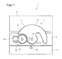
- Fig. 1 schematically shows a side view of an adjusting and locking unit 1 according to the invention for a sliding and pivoting door or wall 20 of a partition wall system in a first position I.
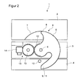
- Fig. 2 schematically shows a side view of the adjustment and locking unit 1 according to the invention Fig. 1 in a second position II.
- Fig. 3 schematically shows a side view of the adjustment and locking unit 1 according to the invention Fig. 1 in a third position III.
- the adjusting and locking unit 1 has an upper part 2, which is fastened to a running rail 30, a central part 3, which is fastened to a movable carriage profile 31 of the door or wall 20, and a lower part 4, which on the door or wall 20th self-fastened.
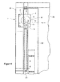
- the running rail 30, the carriage profile 31 and the sliding and pivoting door / wall 20, also referred to as rotary sliding sash are in Fig. 4 shown.
- the adjusting and locking unit 1 has a rotatably mounted closure element 5, which is rotatably mounted on the central part 3 about an axis of rotation 6. Furthermore, an adjusting mechanism 15 for rotating the closure element 5 between the first position I, the second position II and the third position III is provided. In the first position I engages the closure element 5 for locking the middle part 3 on the upper part 2 in the upper part 2, here in a receptacle 7 in the upper part 2, a, see Fig.
- the closure element 5 engages for locking the central part 3 on the upper part 2 and on the lower part 4, in or on the upper part 2, that is in the receptacle 7 of the upper part 2, and in or on the lower part 4, here in a locking element 10, which is formed as a projecting from the lower part 4 pin, see Fig. 2 .
- a sleeve can be rotatably mounted.
- the closure element 5, in particular a second part 9 or a second end of the closure element 5, the locking element 10, in particular the pin particularly easily engage behind without the occurrence of frictional forces.
- the locking element 10 is advantageously perpendicular to the direction of rotation of the closure element 5 from the lower part 4 forth.
- the second part 9, in particular a second end, of the closure element 5 can easily reach into engagement with the locking element 10 in order to lock the middle part 3 to the lower part 4.
- the closure element 5 and the locking element 10 can be matched to one another in such a way that upon reaching the third position III, as in FIG Fig. 3 illustrated, the lower part 4 and thus the rotary sliding wing 20 are raised by the closure element 5.
- the closure element 5 has an approximately circular segment-shaped or sickle-shaped shape.
- the second part 8 and a second end of the closure element 5 is sickle-shaped, so that the closure element 5 when reaching the third position III, the locking element 10, in particular the locking element formed as a pin 10, can engage behind for locking.
- the second end thus has a crescent-shaped projection 11 for engagement in the locking element 10 or for engaging behind this locking element 10 of the lower part 4.
- the closure element 5 of the adjusting and locking unit 1 also has a sprocket segment 12.
- the adjusting mechanism 15 of the adjusting and locking unit 1 has a gear 13.
- the gear 13 is in operative engagement with the sprocket segment 12. That is, by the engagement of the gear 13 of the adjusting mechanism 15 in the sprocket segment 12, a defined rotation of the closure element 5 is ensured about its axis of rotation 6.
- the adjusting mechanism 15 of the adjusting and locking unit 1 preferably further comprises a drive element 14, in particular a drive worm, for rotating the gear 13 and thus of the closure element 5.
- the gearwheel 13 can be actuated via the drive element 14 in order to move the closure element 5 into the first position I, the second position II or the third position III.
- the preferably formed as a drive screw drive element 14 engages in the teeth of the gear 13 a.
- the drive element 14 can be driven via a crank or electrically via a motor-gear unit.
- the crank may for example be a hexagon socket wrench or have a hexagon socket wrench.
- An engine-transmission unit can also be driven remotely.
- Fig. 4 shows the adjustment and locking unit 1 according to the invention in the third position III in a side view.
- the upper part 2 of the adjusting and locking unit 1 is attached to the running rail 30.
- the middle part 3 of the adjusting and locking unit 1 is fixed to the carriage profile 31, and the lower part 4 on the rotary sliding wing 20 of the Partition wall system itself.
- the rotary sliding panel 20 along the guide rail 30 can be moved.
- a pivoting of the rotary sliding leaf 20 is blocked by the engagement of the closure element 5 in the pin 10 on the rotary sliding leaf 20 or on a cover or a frame attachment 32 in which or the rotary sliding leaf 20 is arranged.
- the rotary sliding panel 20 and the adjusting and locking unit 1 are part of the partition wall system.
- the rotary sliding panel 20 is preferably designed as a horizontal rotary sliding panel 20.
- the partition wall system is advantageously a partition wall system for horizontal rotary sliding panels 20.
- Fig. 5 shows a side view of an adjusting and locking unit 40 according to the prior art.
- the adjustment to the three types of closure is made in the partition wall system according to the prior art by two screws, namely by a locking screw 41 and by a locking screw 43.
- the screws 41, 43 are by a rotational movement by means of their respective thread 42, 44 in corresponding counterparts in the upper part 2 and the middle part 3 screwed.
- These screws 41, 43 are operated from the bottom by means of a crank handle, which has at its upper end a hexagon socket wrench.
- this hexagon socket wrench both the locking screw 41 and the locking screw 43 can be screwed in or out.
- a disadvantage of this adjustment and locking unit 40 is that to obtain one of the types of closure two screws 41, 43 must be operated.
Landscapes
- Engineering & Computer Science (AREA)
- Structural Engineering (AREA)
- Physics & Mathematics (AREA)
- Architecture (AREA)
- Electromagnetism (AREA)
- Civil Engineering (AREA)
- Wing Frames And Configurations (AREA)
- Power-Operated Mechanisms For Wings (AREA)
- Mechanical Engineering (AREA)
Abstract
Description
- Die Erfindung betrifft eine Feststell- und Verriegelungseinheit für verschiebbare und schwenkbare Türen und/oder Wände, die beweglich über Laufrollen an/in einer Laufschiene befestigt sind. Die Erfindung betrifft ferner ein Trennwandsystem, aufweisend eine Laufschiene, zwei oder mehr verschiebbare und verschwenkbare Türen und/oder Wände, die beweglich über Laufrollen an und/oder in der Laufschiene geführt sind, für jede Tür oder Wand zumindest ein bewegliches Laufwagenprofil, an dem eine oder mehr Laufrollen befestigt sind, sowie für wenigstens eine der Türen oder Wände eine Verstell- und Verriegelungseinheit.
- Ein System aus Schiebewänden beziehungsweise -türen weist festmontierte Laufschienen mit entsprechenden Schienenverzweigungen auf, die es zulassen, Teile oder die gesamte darunter angeordnete Einheit, das heißt, insbesondere einen oder mehrere Schiebeflügel des Trennwandsystems zu verschieben oder in einer Seitenlage zu parken. Dieses geschieht immer dann, wenn zum Beispiel ein Raum abgeteilt werden oder aber ein Raum in mehrere kleinere Räume aufgeteilt werden soll. Ein weiterer Anwendungsbereich eines Trennwandsystems aus Schiebewänden beziehungsweise -türen ist heute in zunehmendem Maße der Einsatz von Türwandelementen im Gaststätten- und Geschäftsbereich. Hier kann je nach Witterungslage die gesamte Türwandfront beseitigt oder aber es können auch nur Teile dieser Türwandfront verschoben oder verschwenkt werden.
- Trennwandsysteme beziehungsweise Systeme aus Schiebewänden oder Schiebetüren dieser Art sind aus der
DE 35 22 824 A1 sowie derDE 31 48 464 A1 zu entnehmen. Um diese Anlagen jedoch schnell und ohne große Kraftaufwendung verändern zu können, sind die Trenn- beziehungsweise Türwandelemente mit sogenannten Feststellern, die sich am oberen Ende eines Elementes befinden und durch Herausnahme bzw. Hereinnahme einer Verriegelung gelöst oder festgestellt werden können, ausgerüstet. Dieses wird jedoch in dem Augenblick problematisch, wenn bei hohen Trennwandsystemen von über 2m vom Boden aus gemessen nicht mehr jede Person diese Verriegelung ohne Zuhilfenahme von Leitern oder dergleichen erreichen kann. - Bei derzeit bekannten Systemen mit verschiebbaren und/oder schwenkbaren Türen und/oder Wänden, insbesondere im Bereich der Horizontalschiebewände beziehungsweise -türen, wird ein Element beziehungsweise ein Dreh-Schiebeflügel derzeit durch eine Feststell- und Verriegelungseinheit, die zwei Schrauben aufweist, gesichert, wobei die Schrauben durch eine Drehbewegung mittels ihres Gewindes in ein entsprechendes Gegenstück geschraubt werden. Eine derartige Feststell- und Verriegelungseinheit für verschiebbare und/oder schwenkbare Türen und/oder Wände ist beispielsweise aus der
EP 0 562 073 B1 bekannt. Die Feststellund Verriegelungseinheit besteht aus einem Oberteil, einem Mittelteil und einem Unterteil, welche untereinander platziert sind. Diese drei Teile werden außen auf die Türanlage mittels Befestigungsschrauben angebracht. Dabei befindet sich innerhalb der Einheit je eine Schraube für den Feststell- und für den Verriegelungsvorgang. Bedient werden diese Schrauben vom Boden aus mit Hilfe einer Gelenkkurbel, die an ihrem oberen Ende einen Kugelsechskantstiftschlüssel hat. Mittels dieses Kugelsechskantstiftschlüssels können sowohl die Feststellschraube, als auch die Verriegelungsschraube herein- oder herausgedreht werden. - Soll beispielsweise eine Tür beziehungsweise ein Türwandelement verschlossen werden, so wird die Feststellschraube, welche sich im Mittelteil der Einheit befindet, durch eine Drehbewegung in das darüber befindliche, an der Laufschiene des Türwandsystems befestigte Oberteil der Einheit geschraubt. Dadurch sind zwei Teile der Einheit, nämlich Ober- und Unterteil, miteinander verbunden, und der Türflügel lässt sich nicht mehr seitlich verschieben. Damit auch die Pendellage des Türflügels quasi im Wesentlichen senkrecht zur seitlichen Verschiebung gesichert werden kann, kann die zweite Verriegelungsschraube, welche sich im Unterteil der Einheit befindet, in das Mittelteil der Einheit geschraubt werden. Durch diese Verschraubungsart kann die gesamte Tür beziehungsweise ein Türwandelement festgesetzt werden. Ober-, Mittel- und Unterteil bilden eine Einheit.
- Soll nun ein Dreh-Schiebeflügel in eine Parkposition gebracht werden, so ist die Feststellverbindung entsprechend zu lösen, und der Dreh-Schiebeflügel lässt sich innerhalb der Laufschiene verschieben. Ist nur ein Pendeln des Dreh-Schiebeflügels erwünscht, so muss die Verbindung der Feststellschraube mit der Laufschiene erhalten bleiben. Ferner muss die Verriegelungsschraube aus dem Mittelteil herausgedreht werden, und der Dreh-Schiebeflügel beziehungsweise die gesamte Dreh-Schiebeflügelfront ist in ihrem Schwenkbereich nicht mehr festgesetzt. Zur Betätigung der Schrauben werden Gelenkkurbeln verwendet. Dadurch ist das Gefahrenpotential bei der Verstellung der Verriegelung und Feststellung annähernd auf null herabgesetzt, insbesondere weil keine zusätzlichen Einrichtungen benutzt werden müssen.
- Wenn allerdings eine der Schrauben nicht sauber eingedreht wird, leidet das Gewinde der entsprechenden Schraube. Das kann bis zur völligen Deformation des Gewindes und damit der Schraube führen, sodass die entsprechende Schraube nicht mehr in das Oberteil oder das Mittelteil eingeschraubt werden kann. Insbesondere ist der Bedienkomfort nicht optimal durch die Bedienungsabfolge. Als Folge daraus ist es nicht mehr möglich, ein Verschwenken und/oder ein Verschieben einer Tür oder einer Wand zu unterbinden, sodass das gesamte Trennwandsystem instabil wird.
- Es ist Aufgabe der vorliegenden Erfindung, die voranstehend beschriebenen Nachteile bekannter Feststell- und Verriegelungseinheiten für verschiebbare und schwenkbare Türen und/oder Wände, die beweglich über Laufrollen an/in einer Laufschiene befestigt sind, beziehungsweise bekannter Trennwandsysteme zumindest teilweise zu beheben. Insbesondere ist es Aufgabe der vorliegenden Erfindung, eine eingangs genannte Feststell- und Verriegelungseinheit beziehungsweise ein Trennwandsystem zur Verfügung zu stellen, die in bedienerfreundlicher, einfacher und sicherer Weise gewährleisten, dass eine verschiebbare und schwenkbare Tür oder Wand wahlweise in einer der folgenden Zustände der Tür oder der Wand positioniert werden kann:
- 1) Schieben blockiert und Drehen frei,
- 2) Schieben und Drehen blockiert,
- 3) Schieben frei und Drehen blockiert.
- Die voranstehende Aufgabe wird erfindungsgemäß durch eine Verstellund Verriegelungseinheit mit den Merkmalen gemäß dem unabhängigen Patentanspruch 1 sowie durch ein Trennwandsystem mit den Merkmalen gemäß Patentanspruch 14 gelöst. Weitere Merkmale und Details der Erfindung ergeben sich aus den Unteransprüchen, der Beschreibung und den Zeichnungen. Dabei gelten Merkmale und Details, die in Zusammenhang mit der erfindungsgemäßen Verstell- und Verriegelungseinheit beschrieben sind, selbstverständlich auch im Zusammenhang mit dem erfindungsgemäßen Trennwandsystem und jeweils umgekehrt, sodass bezüglich der Offenbarung zu den einzelnen Erfindungsaspekten stets wechselseitig Bezug genommen wird beziehungsweise werden kann.
- Gemäß einem ersten Aspekt der Erfindung wird die Aufgabe durch eine Verstell- und Verriegelungseinheit für verschiebbare und verschwenkbare Türen und/oder Wände, die beweglich über Laufrollen an und/oder in einer Laufschiene geführt sind, gelöst. D. h. die Verstell- und Verriegelungseinheit ist für derartige Türen bzw. Wände vorgesehen bzw. eingerichtet, an diesen eingesetzt zu werden. Die Verstell- und Verriegelungseinheit weist ein Oberteil, welches an der Laufschiene befestigbar ist, ein Mittelteil, welches an einem beweglichen Laufwagenprofil einer Tür beziehungsweise einer Wand befestigbar ist, und ein Unterteil auf, welches an dieser Tür beziehungsweise Wand befestigbar ist. Des Weiteren ist die Verstell- und Verriegelungseinheit dadurch gekennzeichnet, dass diese ein Arretierungsmittel umfasst. Die Verstell- und Verriegelungseinheit ist erfindungsgemäß eingerichtet, mittels Verstellens dieses einen Arretierungsmittels in einer ersten Stellung das Mittelteil an dem Oberteil, nicht aber an dem Unterteil zu arretieren. D. h. das Unterteil bleibt in Bezug auf das Mittelteil frei bewegbar, wohingegen die Bewegung des Oberteils in Bezug auf das Mittelteil zumindest in eine Richtung verhindert ist. Die Verstell- und Verriegelungseinheit ist ferner eingerichtet, mittels Verstellens dieses Arretierungsmittels in einer zweiten Stellung das Mittelteil an dem Oberteil und an dem Unterteil zu arretieren. D. h. in dieser Stellung sind Ober- und Unterteil an einer jeweiligen Bewegung in Bezug auf das Mittelteil jeweils zumindest in eine Richtung gehindert. Schließlich ist die Verstell- und Verriegelungseinheit eingerichtet, mittels Verstellens dieses Arretierungsmittels in einer dritten Stellung das Mittelteil an dem Unterteil, nicht aber an dem Oberteil zu arretieren. D. h. nun das Oberteil in Bezug auf das Mittelteil frei bewegbar, wohingegen die Bewegung des Unterteils in Bezug auf das Mittelteil zumindest in eine Richtung verhindert ist. Da nur ein Element verstellt werden muss, um alle drei Stellungen bewirken zu können, ist die Bedienung enorm vereinfacht.
- Vorzugsweise ist das Arretierungsmittel mittels eines drehbar gelagerten Verschlusselements gebildet. Das Verschlusselement ist an dem Mittelteil um eine Drehachse drehbar gelagert. D. h. das vorgenannte Verstellen erfolgt mittels Verdrehens des Verschlusselements als Arretierungsmittel. Erfindungsgemäß ist ferner ein Verstellmechanismus vorgesehen, mittels dessen das Verschlusselement zwischen jeweiligen, mit der ersten, zweiten und dritten Stellung korrespondierenden Positionen verdrehbar angeordnet ist. In einer ersten Position greift das Verschlusselement zur Arretierung des Mittelteils an dem Oberteil in oder an das Oberteil ein, sodass sich die Verstell- und Verriegelungseinheit in der vorgenannten, ersten Stellung befindet. In der zweiten Position greift das Verschlusselement zur Arretierung des Mittelteils an dem Oberteil und an dem Unterteil in oder an das Oberteil und in oder an das Unterteil ein, sodass sich die Verstell- und Verriegelungseinheit in der vorgenannten, zweiten Stellung befindet. Und in der fehlenden, dritten Position greift das Verschlusselement zur Arretierung des Mittelteils an dem Unterteil in oder an das Unterteil ein, sodass sich die Verstell- und Verriegelungseinheit in der dritten Stellung befindet. Dies ist eine besonders bedienerfreundliche Ausführung. Es ist nur eine Stange erforderlich, die beispielsweise ähnlich einer Markisen-Drehstange nur das Verschlusselement drehen muss, um die vorgenannten drei Stellungen der erfindungsgemäßen Verstell- und Verriegelungseinheit zu erreichen.
- Durch eine derartig ausgebildete Verstell- und Verriegelungseinheit kann also durch eine einfache Drehbewegung des Verschlusselementes sichergestellt werden, dass das Verschlusselement die drei verschiedenen Stellungen einnehmen kann. Hierdurch können bei einer verschiebbaren und verschwenkbaren Tür oder Wand, einem so genannten Dreh-Schiebeflügel, die gewünschten Verschlussarten einfach und sicher abgebildet werden. In der ersten Stellung des Verschlusselementes greift das Verschlusselement in oder an das Oberteil ein, sodass dadurch ein Schieben eines Dreh-Schiebeflügels blockiert aber ein Drehen ermöglicht ist. In der zweiten Stellung greift das Verschlusselement sowohl in oder an das Oberteil als auch in oder an das Unterteil ein, sodass ein Schieben und ein Drehen beziehungsweise Verschwenken eines Dreh-Schiebeflügels, an dem die Verstell- und Verriegelungseinheit befestigt ist, verhindert ist. In der dritten Stellung verhindert das Verschlusselement ein Drehen beziehungsweise Verschwenken des Dreh-Schiebeflügels, ermöglicht aber ein Schieben des Dreh-Schiebeflügels.
- Zuvor und in der weiteren Beschreibung wird sowohl eine verschiebbare und verschwenkbare Tür, als auch eine verschiebbare und verschwenkbare Wand auch als Dreh-Schiebeflügel bezeichnet.
- Die Dreh-Schiebeflügel sind beweglich über Laufrollen, die an einem oder mehreren Laufwagenprofilen angeordnet sind, an und/oder in einer Laufschiene geführt. Das Oberteil der Verstell- und Verriegelungseinheit dient zur Befestigung an der Laufschiene. Insbesondere wird das Oberteil über einer Laufschienenbefestigung mit der feststehenden Laufschiene kraftschlüssig und gegebenenfalls auch formschlüssig verbunden. Das Mittelteil der Verstell- und Verriegelungseinheit ist an einem Laufwagenprofil befestigbar. An dem Laufwagenprofil sind eine oder mehrere Laufrollen angeordnet, die an oder in der Laufschiene geführt sind, um einen jeweiligen der Dreh-Schiebeflügel entlang der Laufschiene zu verschieben. Vorzugsweise kann das Mittelteil über eine Befestigung kraft- und gegebenenfalls auch formschlüssig an dem Laufwagenprofil befestigt werden. Das Unterteil der Verstell- und Verriegelungseinheit ist an dem DrehSchiebeflügel, das heißt einer Tür oder einer Wand, direkt oder indirekt befestigt. Dabei kann das Unterteil direkt an dem Dreh-Schiebeflügel oder indirekt, beispielsweise über eine Rahmenbefestigung, an dem Dreh-Schiebeflügel befestigt sein. Zur Befestigung dienen insbesondere Schraubelemente.
- Das Verschlusselement der Verstell- und Verriegelungseinheit ist drehbar an dem Mittelteil gelagert. Vorzugsweise ist das Verschlusselement derart an dem Mittelteil gelagert, dass es parallel zu dem Mittelteil verdreht werden kann. Das Verschlusselement weist insbesondere einen ebenen Grundkörper auf. Das Verschlusselement kann über den Verstellmechanismus der Verstell- und Verriegelungseinheit verdreht werden. Dabei kann der Verstellmechanismus das Verschlusselement in die erste Stellung, in die zweite Stellung oder die dritte Stellung bewegen. In der ersten Stellung verbindet das Verschlusselement das Mittelteil mit dem Oberteil, sodass diese nicht mehr zueinander verschoben werden können. In dieser ersten Stellung greift das Verschlusselement nicht in oder an das Unterteil ein, sodass der Dreh-Schiebeflügel verschwenkt beziehungsweise verdreht werden kann. In der zweiten Stellung blockiert das Verschlusselement sowohl das Unterteil als auch das Oberteil der Verstell- und Verriegelungseinheit, sodass dadurch ein Schieben und ein Verschwenken des Dreh-Schiebeflügels blockiert sind. In der dritten Stellung gibt das Verschlusselement das Oberteil frei, sodass ein Schieben des Dreh-Schiebeflügels ermöglicht aber durch den Eingriff am Unterteil ein Verschwenken des Dreh-Schiebeflügels verhindert ist.
- Die Verstell- und Verriegelungseinheit erhöht den Bedienkomfort zum Feststellen oder Freigeben eines Verschwenkens und eines Verschiebens einer verschiebbaren und verschwenkbaren Tür oder Wand eines Trennwandsystems, insbesondere eines horizontalen Trennwandsystems.
- Vorteilhaft bei der erfindungsgemäßen Verstell- und Verriegelungseinheit ist ferner, dass die unterschiedlichen Stellungen und damit die unterschiedlichen Verschlussarten des Dreh-Schiebeflügels durch eine einzige Betätigung erreicht werden können. Dadurch kann ein Dreh-Schiebeflügel einfach und schnell in eine bestimmte Position überführt beziehungsweise durch eine bestimmte Verschlussart blockiert werden. Insbesondere kann durch die Reduzierung der Verstell- und Verriegelungseinheit von zwei Schraubverbindungen auf ein einziges Verschlusselement eine Fehlbedienung der Verstell- und Verriegelungseinheit und der damit verbundenen oberen Verriegelung eines Dreh-Schiebeflügels eines Trennwandsystems verhindert werden. Durch eine einzige drehende Betätigung kann die Verstell- und Verriegelungseinheit drei verschiedene Stellungen einnehmen, um bei einem Dreh-Schiebeflügel die benötigten Verschlussarten abzubilden, nämlich:
- 1) Drehen frei und Schieben gesperrt,
- 2) Drehen und Schieben gesperrt,
- 3) Drehen gesperrt und Schieben frei.
- Im Lichte der Erfindung bedeutet ein Eingriff des Verschlusselementes in oder an das Oberteil, dass das Verschlusselement an dem Oberteil arretiert wird. Dies kann durch ein Eingreifen des Verschlusselementes in das Oberteil oder ein Greifen des Verschlusselementes an dem Oberteil erfolgen.
- Gemäß einer bevorzugten Weiterentwicklung der Erfindung kann bei einer Verstell- und Verriegelungseinheit vorgesehen sein, dass das Oberteil eine Aufnahme, insbesondere eine Vertiefung oder Nut, zum Eingriff, insbesondere zum formschlüssigen Eingriff, eines ersten Teils des Verschlusselementes aufweist. Das Oberteil, das Mittelteil und das Unterteil der Verstell- und Verriegelungseinheit sind vorzugsweise vertikal untereinander angeordnet, also entlang einer Richtung von der Laufschiene zum jeweiligen Dreh-Schiebeflügel. Die Aufnahme im Oberteil ist vorzugsweise an der dem Mittelteil zugewandten Seite des Oberteils angeordnet. Durch ein Verdrehen des Verschlusselementes mittels des Verstellmechanismus greift das Verschlusselement formschlüssig in die Aufnahme ein. In diesem Zustand ist die erste Stellung erreicht. Durch den Eingriff zumindest eines Teils des Verschlusselementes in die Aufnahme ist das Mittelteil an dem Oberteil arretiert, sodass ein Verschieben des Mittelteils beziehungsweise des Laufwagenprofils, an dem das Mittelteil sitzt, verhindert ist. Vorzugsweise ist die Aufnahme im Oberteil als Vertiefung beziehungsweise Nut ausgebildet. Insbesondere ist die Aufnahme durch eine sichelförmige oder kreissegmentförmige Form gebildet, in die das vorzugsweise sichelförmige oder kreissegmentförmige Verschlusselement, insbesondere erste Teil des Verschlusselementes, formschlüssig eingreifen kann.
- Bevorzugt ist eine Verstell- und Verriegelungseinheit, bei der das Unterteil ein Verriegelungselement, insbesondere einen Verriegelungsvorsprung, zum Eingriff eines zweiten Teils des Verschlusselementes aufweist. Das Verriegelungselement kann beispielsweise ein Zapfen sein, der aus dem Unterteil hervorsteht. Dabei steht das Verriegelungselement vorteilhafterweise senkrecht zur Verdrehrichtung des Verschlusselementes aus dem Unterteil hervor. Hierdurch kann der zweite Teil, insbesondere ein zweites Ende, des Verschlusselementes in Eingriff mit dem Verriegelungselement gelangen, um das Mittelteil an dem Unterteil zu arretieren. Insbesondere können das Verschlusselement und das Verriegelungselement derart aufeinander abgestimmt sein, dass bei dem Erreichen der dritten Stellung das Unterteil und damit der Dreh-Schiebeflügel durch das Verschlusselement angehoben werden.
- Gemäß einer bevorzugten Weiterentwicklung der Erfindung kann vorgesehen sein, dass das Verschlusselement eine kreissegmentförmige oder annähernd kreissegmentförmige Gestalt aufweist. Bevorzugt ist zumindest der zweite Teil beziehungsweise das zweite Ende des Verschlusselementes sichelförmig ausgebildet, sodass dieses bei dem Erreichen der dritten Stellung das Verriegelungselement, insbesondere den Verriegelungsvorsprung, zur Arretierung hintergreifen kann. Das heißt, bevorzugt weist das Verschlusselement, insbesondere der zweite Teil beziehungsweise das zweite Ende des Verschlusselementes, einen sichelförmigen Vorsprung zum Eingriff in das Verriegelungselement beziehungsweise zum Hintergreifen des Verriegelungselementes des Unterteils auf.
- Ferner kann vorteilhafterweise bei einer Verstell- und Verriegelungseinheit vorgesehen sein, dass das Verriegelungselement als ein aus dem Unterteil hervorstehender Zapfen ausgebildet ist, um den eine Hülse drehbar gelagert ist. Hierdurch kann der zweite Teil beziehungsweise das zweite Ende des Verschlusselementes das Verriegelungselement, insbesondere den Zapfen, besonders einfach, ohne das Auftreten von Reibkräften, hintergreifen.
- Des Weiteren kann bei einer Verstell- und Verriegelungseinheit vorgesehen sein, dass das Verschlusselement ein Zahnkranzsegment und der Verstellmechanismus ein Zahnrad aufweisen, wobei zur Verdrehung des Verschlusselementes das Zahnrad in operativem Eingriff mit dem Zahnkranzsegment steht. Durch den Eingriff eines Zahnrades des Verstellmechanismus in ein Zahnkranzsegment des Verschlusselementes ist eine definierte Bewegung des Verschlusselementes gewährleistet. Insbesondere ist das Zahnkranzsegment derart an dem Verschlusselement angeordnet ist, dass dieses um die Drehachse des Verschlusselementes drehbar ist. Hierdurch kann bei einer Drehung des Zahnrades des Verstellmechanismus das Verschlusselement um die Drehachse gedreht werden.
- Gemäß einer weiteren bevorzugten Weiterbildung der Erfindung kann bei einer Verstell- und Verriegelungseinheit vorgesehen sein, dass der Verstellmechanismus ein Antriebselement, insbesondere eine Antriebsschnecke, zum Verdrehen des Verschlusselementes aufweist. Das heißt, der Verstellmechanismus, insbesondere das Zahnrad, kann über ein Antriebselement betätigt werden, um das Verschlusselement in die erste, die zweite oder die dritte Stellung zu bewegen. Bevorzugt ist das Antriebselement zum Eingriff in das Zahnrad ausgebildet ist. So kann das Antriebselement als Antriebsschnecke ausgebildet sein, die in die Zähne des Zahnrads eingreifen kann. Durch den Eingriff der Antriebsschnecke in das Zahnrad kann eine Drehbewegung der Antriebsschnecke auf das Zahnrad und damit auf das Verschlusselement übertragen werden.
- Das Antriebselement kann über eine Kurbel oder elektrisch über eine Motor-Getriebe-Einheit antreibbar sein. Das bedeutet, im einfachsten Fall kann in das Antriebselement beziehungsweise in die Antriebsschnecke eine Kurbel eingesteckt werden, sodass durch eine Drehung der Kurbel das Antriebselement betätigt werden kann. Beispielsweise kann die Kurbel ein Kugelsechskantstiftschlüssel sein oder aufweisen.
- Das Oberteil, das Mittelteil und das Unterteil der Verstell- und Verriegelungseinheit sind vorzugsweise aus Leichtmetall oder Kunststoff ausgebildet. Hierdurch kann Gewicht eingespart werden.
- Gemäß einem zweiten Aspekt der Erfindung wird die Aufgabe durch ein Trennwandsystem gelöst. Das Trennwandsystem weist eine Laufschiene, zwei oder mehr verschiebbare und/oder verschwenkbare Türen und/oder Wände auf, die beweglich über Laufrollen an und/oder in der Laufschiene geführt sind. Für jede Tür oder Wand weist das Trennwandsystem ferner zumindest ein bewegliches Laufwagenprofil auf, an dem eine oder mehrere Laufrollen befestigt sind. Zudem weist das Trennwandsystem für wenigstens eine der Türen oder Wände eine Verstell- und Verriegelungseinheit auf. Dabei ist die Verstell- und Verriegelungseinheit gemäß dem ersten Aspekt der Erfindung, insbesondere nach zumindest einem der Ansprüche 1 bis 13, ausgebildet. Bevorzugt weist das Trennwandsystem eine Vielzahl von horizontalen Dreh-Schiebeflügeln auf, die in Reihe zueinander angeordnet werden können. Ein derartiges Trennwandsystem ermöglicht ein bedienerfreundliches Feststellen eines oder mehrerer dieser Dreh-Schiebeflügel. Hierdurch kann das Trennwandsystem auf jede gewünschte Position leicht und schnell eingestellt werden. Dadurch, dass die Verstell- und Verriegelungseinheiten einfach betätigt werden können, kann jeder der Dreh-Schiebeflügel schnell individuell verschlossen werden. Das bedeutet, jeder Dreh-Schiebeflügel kann durch seine Verstell- und Verriegelungseinheit durch eine der drei Verschlussarten blockiert werden. Das heißt, bei dem Trennwandsystem kann in einer bedienerfreundlichen, einfachen und sicheren Weise gewährleistet werden, dass die verschiebbaren und schwenkbaren Türen und/oder Wände in einer der folgenden Zustände positioniert werden können:
- 1) Schieben blockiert und Drehen frei,
- 2) Schieben und Drehen blockiert,
- 3) Schieben frei und Drehen blockiert.
- Die Türen des Trennwandsystems sind vorzugsweise aus Glas gebildet. Die Wände sind vorteilhafterweise aus Leichtmetall oder Kunststoff gebildet. Bei einem bevorzugten Trennwandsystem können nur Türen, insbesondere Glastüren, vorgesehen sein. Bei einem anderen bevorzugten Trennwandsystem können nur Wände vorgesehen sein. Ebenso können bei einem Trennwandsystem sowohl Türen, als auch Wände vorgesehen sein. Vorzugsweise ist bei dem Trennwandsystem eine Laufschiene vorgesehen. Es können aber auch mehrere Laufschienen fluchtend zueinander angeordnet sein. Die Laufschiene kann auch entsprechende Schienenverzweigungen aufweisen. Jeder Dreh-Schiebeflügel ist vorteilhafterweise über zwei Laufwagenprofile, mit zumindest je einer Laufrolle, an der Laufschiene beweglich geführt. Durch das Verschlusselement der Verstellund Verriegelungseinheit können die jeweiligen Dreh-Schiebeflügel leicht in die jeweils gewünschte Verschlussart überführt werden. Die Verstellung der Stellungen eines Verschlusselementes einer Verstell- und Verriegelungseinheit erfolgt über das Antriebselement der jeweiligen Verstell- und Verriegelungseinheit. Das Antriebselement kann eine Antriebsschnecke aufweisen, die eine Aufnahme für eine Kurbel aufweist. Alternativ kann das Antriebselement eine Motor-Getriebe-Einheit aufweisen, sodass die Verstellung des Verschlusselementes elektrisch erfolgen kann. Der Motor des Antriebselementes kann auch durch eine Fernbedienung betätigt werden. Hierdurch kann die Verdrehung des Verschlusselementes ferngesteuert werden.
- Besonders bevorzugt sind die zuvor erwähnten Dreh-Schiebeflügel als horizontale Dreh-Schiebeflügel ausgebildet. Das Trennwandsystem ist vorteilhafterweise ein Trennwandsystem für horizontale Dreh-Schiebeflügel.
- Die vorliegende Erfindung ist weiter beschrieben mit Bezug zu den zugehörigen Zeichnungen. Es ist schematisch dargestellt in:
- Figur 1
- in einer Seitenansicht eine erfindungsgemäße Verstell- und Verriegelungseinheit in einer ersten Stellung,
- Figur 2
- in einer Seitenansicht die Verstell- und Verriegelungseinheit von
Figur 1 in einer zweiten Stellung, - Figur 3
- in einer Seitenansicht die Verstell- und Verriegelungseinheit von
Figur 1 in einer dritten Stellung, - Figur 4
- in einer Seitenansicht der Verstell- und Verriegelungseinheit von
Figur 1 in der dritten Stellung und befestigt an einer Laufschiene, einem Laufwagenprofil und einem Dreh-Schiebeflügel eines Trennwandsystems, und - Figur 5
- in einer Seitenansicht eine Verstell- und Verriegelungseinheit gemäß dem Stand der Technik,
- Elemente mit der gleichen Funktion und Funktionsweise sind in den
Fig. 1 bis 5 mit den gleichen Bezugszeichen versehen. -
Fig. 1 zeigt schematisch in einer Seitenansicht eine erfindungsgemäße Verstell- und Verriegelungseinheit 1 für eine verschiebbare und verschwenkbare Tür oder Wand 20 eines Trennwandsystems in einer ersten Stellung I.Fig. 2 zeigt schematisch in einer Seitenansicht die erfindungsgemäße Verstell- und Verriegelungseinheit 1 gemäßFig. 1 in einer zweiten Stellung II.Fig. 3 zeigt schematisch in einer Seitenansicht die erfindungsgemäße Verstell- und Verriegelungseinheit 1 gemäßFig. 1 in einer dritten Stellung III. - Die Verstell- und Verriegelungseinheit 1 weist ein Oberteil 2, welches an einer Laufschiene 30 befestigbar ist, ein Mittelteil 3, welches an einem beweglichen Laufwagenprofil 31 der Tür beziehungsweise Wand 20 befestigbar ist, und ein Unterteil 4 auf, welches an der Tür beziehungsweise Wand 20 selbst befestigbar ist. Die Laufschiene 30, das Laufwagenprofil 31 und die verschiebbare und verschwenkbare Tür/Wand 20, auch als Dreh-Schiebeflügel bezeichnet, sind in
Fig. 4 dargestellt. - Die Verstell- und Verriegelungseinheit 1 weist ein drehbar gelagertes Verschlusselement 5 auf, welches an dem Mittelteil 3 um eine Drehachse 6 drehbar gelagert ist. Ferner ist ein Verstellmechanismus 15 zur Verdrehung des Verschlusselementes 5 zwischen der ersten Stellung I, der zweiten Stellung II und der dritten Stellung III vorgesehen. In der ersten Stellung I greift das Verschlusselement 5 zur Arretierung des Mittelteils 3 an dem Oberteil 2 in das Oberteil 2, hier in eine Aufnahme 7 im Oberteil 2, ein, siehe
Fig. 1 . In der zweiten Stellung II greift das Verschlusselement 5 zur Arretierung des Mittelteils 3 an dem Oberteil 2 und an dem Unterteil 4, in oder an das Oberteil 2, das heißt in die Aufnahme 7 des Oberteils 2, und in oder an das Unterteil 4, hier in ein Verriegelungselement 10 ein, das als ein aus dem Unterteil 4 hervorstehender Zapfen ausgebildet ist, sieheFig. 2 . Um das Verriegelungselement 10, insbesondere den Zapfen, kann eine Hülse drehbar gelagert sein. Hierdurch kann das Verschlusselement 5, insbesondere ein zweiter Teil 9 beziehungsweise ein zweites Ende des Verschlusselementes 5 das Verriegelungselement 10, insbesondere den Zapfen, besonders einfach, ohne das Auftreten von Reibkräften, hintergreifen. Das Verriegelungselement 10 steht vorteilhafterweise senkrecht zur Verdrehrichtung des Verschlusselementes 5 aus dem Unterteil 4 hervor. Hierdurch kann der zweite Teil 9, insbesondere ein zweites Ende, des Verschlusselementes 5 einfach in Eingriff mit dem Verriegelungselement 10 gelangen, um das Mittelteil 3 an dem Unterteil 4 zu arretieren. Insbesondere können das Verschlusselement 5 und das Verriegelungselement 10 derart aufeinander abgestimmt sein, dass bei dem Erreichen der dritten Stellung III, wie inFig. 3 dargestellt, das Unterteil 4 und damit der Dreh-Schiebeflügel 20 durch das Verschlusselement 5 angehoben werden. - Das Verschlusselement 5 weist eine annähernd kreissegmentförmige beziehungsweise sichelförmige Gestalt auf. Insbesondere der zweite Teil 8 beziehungsweise ein zweite Ende des Verschlusselementes 5 ist sichelförmig ausgebildet, sodass das Verschlusselement 5 bei dem Erreichen der dritten Stellung III das Verriegelungselement 10, insbesondere das als Zapfen ausgebildete Verriegelungselement 10, zur Arretierung hintergreifen kann. Das zweite Ende weist also einen hier sichelförmigen Vorsprung 11 zum Eingriff in das Verriegelungselement 10 beziehungsweise zum Hintergreifen dieses Verriegelungselementes 10 des Unterteils 4 auf. Das Verschlusselement 5 der Verstell- und Verriegelungseinheit 1 weist ferner ein Zahnkranzsegment 12 auf. Der Verstellmechanismus 15 der Verstell- und Verriegelungseinheit 1 weist ein Zahnrad 13 auf. Zur Verdrehung des Verschlusselementes 5 steht das Zahnrad 13 in operativem Eingriff mit dem Zahnkranzsegment 12. Das heißt, durch den Eingriff des Zahnrades 13 des Verstellmechanismus 15 in das Zahnkranzsegment 12, ist eine definierte Drehung des Verschlusselementes 5 um dessen Drehachse 6 gewährleistet.
- Der Verstellmechanismus 15 der Verstell- und Verriegelungseinheit 1 weist vorzugsweise ferner ein Antriebselement 14, insbesondere eine Antriebsschnecke, zum Verdrehen des Zahnrades 13 und damit des Verschlusselementes 5 auf. Das Zahnrad 13 kann über das Antriebselement 14 betätigt werden, um das Verschlusselement 5 in die erste Stellung I, die zweite Stellung II oder die dritte Stellung III zu bewegen. Das vorzugsweise als Antriebsschnecke ausgebildete Antriebselement 14 greift in die Zähne des Zahnrads 13 ein. Durch den Eingriff der Antriebsschnecke 14 in das Zahnrad 13 kann eine Drehbewegung der Antriebsschnecke 14 auf das Zahnrad 13 und damit über das Zahnkranzsegment 12 auf das Verschlusselement 5 übertragen werden.
- Zum Antreiben des Antriebselementes 14 existieren mehrere Möglichkeiten. So kann das Antriebselement 14 über eine Kurbel oder elektrisch über eine Motor-Getriebe-Einheit angetrieben werden. Die Kurbel kann beispielsweise ein Kugelsechskantstiftschlüssel sein oder einen Kugelsechskantstiftschlüssel aufweisen. Eine Motor-Getriebe-Einheit kann auch ferngesteuert angetrieben werden.
-
Fig. 4 zeigt die erfindungsgemäße Verstell- und Verriegelungseinheit 1 in der dritten Stellung III in einer Seitenansicht. Das Oberteil 2 der Verstellund Verriegelungseinheit 1 ist an der Laufschiene 30 befestigt. Das Mittelteil 3 der Verstell- und Verriegelungseinheit 1 ist an dem Laufwagenprofil 31 befestigt, und das Unterteil 4 an dem Dreh-Schiebeflügel 20 des Trennwandsystems selbst. In dieser dritten Stellung III kann der Dreh-Schiebeflügel 20 entlang der Laufschiene 30 verschoben werden. Eine Verschwenkung des Dreh-Schiebeflügels 20 ist durch den Eingriff des Verschlusselementes 5 in den Zapfen 10 an dem Dreh-Schiebeflügel 20 beziehungsweise an einem Abdeckprofil oder einer Rahmenbefestigung 32 blockiert, in dem bzw. der der Dreh-Schiebeflügel 20 angeordnet ist. - Der Dreh-Schiebeflügel 20 und die Verstell- und Verriegelungseinheit 1 sind Teil des Trennwandsystems. Der Dreh-Schiebeflügel 20 ist vorzugsweise als horizontaler Dreh-Schiebeflügel 20 ausgebildet. Das Trennwandsystem ist ein vorteilhafterweise eine Trennwandsystem für horizontale Dreh-Schiebeflügel 20.
- Der Dreh-Schiebeflügel 20 ist beweglich über Laufrollen an und/oder in der Laufschiene 30 geführt. An der Dreh-Schiebeflügel 20 ist zumindest ein bewegliches Laufwagenprofil 31 vorgesehen, an dem eine oder mehrere Laufrollen befestigt sind. Das Trennwandsystem weist vorzugsweise eine Vielzahl von horizontalen Dreh-Schiebeflügeln 20 auf, die in Reihe zueinander angeordnet werden können. Ein derartiges Trennwandsystem mit Dreh-Schiebeflügeln 20, die über erfindungsgemäße Verstell- und Verriegelungseinheiten 1 an einer Laufschiene 30 gehalten sind, ermöglicht ein bedienerfreundliches Feststellen eines oder mehrerer DrehSchiebeflügel 20. Das Trennwandsystem kann durch das einfach zu verstellende Verschlusselement 5 der jeweiligen Verstell- und Verriegelungseinheiten 1 auf jede gewünschte Position leicht und schnell eingestellt werden. Jeder Dreh-Schiebeflügel 20 kann durch seine ihm zugeordnete Verstell- und Verriegelungseinheit 1 auf eine der drei Verschlussarten:
- 1) Schieben blockiert und Drehen frei,
- 2) Schieben und Drehen blockiert,
- 3) Schieben frei und Drehen blockiert,
eingestellt werden. -
Fig. 5 zeigt in einer Seitenansicht eine Verstell- und Verriegelungseinheit 40 gemäß dem Stand der Technik. Die Einstellung auf die drei Verschlussarten erfolgt bei dem Trennwandsystem gemäß dem Stand der Technik durch zwei Schrauben, nämlich durch eine Feststellschraube 41 und durch eine Verriegelungsschraube 43. Die Schrauben 41, 43 werden durch eine Drehbewegung mittels ihres jeweiligen Gewindes 42, 44 in entsprechende Gegenstücke in dem Oberteil 2 beziehungsweise den Mittelteil 3 geschraubt. Bedient werden diese Schrauben 41, 43 vom Boden aus mit Hilfe einer Gelenkkurbel, die an ihrem oberen Ende einen Kugelsechskantstiftschlüssel hat. Mittels dieses Kugelsechskantstiftschlüssels können sowohl die Feststellschraube 41 als auch die Verriegelungsschraube 43 herein- oder herausgedreht werden. Nachteilig bei dieser Verstell- und Verriegelungseinheit 40 ist, dass zur Erlangung einer der Verschlussarten zwei Schrauben 41, 43 betätigt werden müssen. Wird eine der Schrauben 41, 43 nicht richtig, insbesondere vollständig, in das entsprechende Gegenstück an dem Oberteil 2 oder dem Mittelteil 3 eingedreht, kann das Gewinde 42, 44 der Schraube in Mitleidenschaft gezogen, im schlimmsten Fall zerstört werden. Hierdurch können die entsprechende Schraube 41, 43 nicht mehr in das Oberteil 2 beziehungsweise das Mittelteil 3 eingeschraubt werden und das Verschließen eines Dreh-Schiebeflügels 20 nicht mehr korrekt durchgeführt werden. -
- 1
- Verstell- und Verriegelungseinheit
- 2
- Oberteil
- 3
- Mittelteil
- 4
- Unterteil
- 5
- drehbar gelagertes Verschlusselement
- 6
- Drehachse
- 7
- Aufnahme
- 8
- erster Teil des Verschlusselementes 5
- 9
- zweiter Teil des Verschlusselementes 5
- 10
- Verriegelungselement/ Zapfen
- 11
- sichelförmiger Vorsprung
- 12
- Zahnkranzsegment
- 13
- Zahnrad
- 14
- Antriebselement/ Antriebsschnecke
- 15
- Verstellmechanismus
- 20
- Wand/ Tür/ Dreh-Schiebeflügel
- 30
- Laufschiene
- 31
- Laufwagenprofil
- 32
- Abdeckprofil/ Rahmenbefestigung
- 40
- Verstell- und Verriegelungseinheit
- 41
- Feststellschraube
- 42
- Gewinde
- 43
- Verriegelungsschraube
- 44
- Gewinde
- I
- erste Stellung des Verschlusselementes 5 bzw. der Verstellund Verriegelungseinheit 1
- II
- zweite Stellung des Verschlusselementes 5 bzw. der Verstellund Verriegelungseinheit 1
- III
- dritte Stellung des Verschlusselementes 5 bzw. der Verstellund Verriegelungseinheit 1
Claims (14)
- Verstell- und Verriegelungseinheit (1)• vorgesehen für verschiebbare und verschwenkbare Türen und/ oder Wände (20), die beweglich über Laufrollen an und/oder in einer Laufschiene (30) geführt sind, und• aufweisenddadurch gekennzeichnet, dass- ein Oberteil (2), welches an der Laufschiene (30) befestigbar gestaltet ist,- ein Mittelteil (3), welches an einem beweglichen Laufwagenprofil (31) einer jeweiligen der Türen beziehungsweise Wände (20) befestigbar gestaltet ist, und- ein Unterteil (4), welches an der jeweiligen Tür beziehungsweise Wand (20) befestigbar gestaltet ist,• die Verstell- und Verriegelungseinheit (1) eingerichtet ist, mittels Verstellens ein und desselben Arretierungsmittels (5) der Verstellund Verriegelungseinheit (1)- in einer ersten Stellung (I) das Mittelteil (3) an dem Oberteil (2), nicht aber an dem Unterteil (4) zu arretieren,- in einer zweiten Stellung (II) das Mittelteil (3) an dem Oberteil (2) und an dem Unterteil (4) zu arretieren, und- in einer dritten Stellung (III) das Mittelteil (3) an dem Unterteil (4), nicht aber an dem Oberteil (2) zu arretieren.
- Verstell- und Verriegelungseinheit (1) nach Anspruch 1,
dadurch gekennzeichnet, dass• das Arretierungsmittel (5) mittels eines drehbar gelagerten Verschlusselements (5) gebildet ist, welches an dem Mittelteil (3) um eine Drehachse (6) drehbar gelagert ist,• das Verstellen des Arretierungsmittels (5) mittels Verdrehens des Verschlusselements (5) erfolgt,• ein Verstellmechanismus (15) zum Verdrehen des Verschlusselementes (5) zwischen jeweiligen, mit der ersten (I), zweiten (II) und dritten Stellung (III) korrespondierenden Positionen vorgesehen ist und• das Verschlusselement (5)- in der ersten Position in oder an das Oberteil (2) eingreift, sodass sich die Verstell- und Verriegelungseinheit (1) in der ersten Stellung (I) befindet,- in der zweiten Position in oder an das Oberteil (2) und in oder an das Unterteil (4) eingreift, sodass sich die Verstell- und Verriegelungseinheit (1) in der zweiten Stellung (II) befindet, und- in der dritten Position an dem Unterteil (4) in oder an das Unterteil (4) eingreift, sodass sich die Verstell- und Verriegelungseinheit (1) in der dritten Stellung (III) befindet. - Verstell- und Verriegelungseinheit (1) nach Anspruch 2, dadurch gekennzeichnet, dass das Oberteil (5) eine Aufnahme (7), insbesondere eine Vertiefung oder Nut, zum Eingriff, insbesondere zum formschlüssigen Eingriff, eines ersten Teils (8) des Verschlusselementes (5) aufweist.
- Verstell- und Verriegelungseinheit (1) nach Anspruch 2 oder 3, dadurch gekennzeichnet, dass das Unterteil (4) ein Verriegelungselement (10), insbesondere einen Verriegelungsvorsprung, zum Eingriff eines zweiten Teils (9) des Verschlusselementes (5) aufweist.
- Verstell- und Verriegelungseinheit (1) nach Anspruch 4, dadurch gekennzeichnet, dass das Verschlusselement (5) einen sichelförmigen Vorsprung (11) zum Eingriff in das Verriegelungselement (10) beziehungsweise zum Hintergreifen des Verriegelungselementes (10) des Unterteils (4) aufweist.
- Verstell- und Verriegelungseinheit (1) nach Anspruch 4 oder 5, dadurch gekennzeichnet, dass das Verriegelungselement (10) als ein aus dem Unterteil (4) hervorstehender Zapfen ausgebildet ist, um den eine Hülse drehbar gelagert ist.
- Verstell- und Verriegelungseinheit (1) nach einem der vorhergehenden Ansprüche, dadurch gekennzeichnet, dass das Verschlusselement (5) eine kreissegmentförmige oder annähernd kreissegmentförmige Gestalt aufweist.
- Verstell- und Verriegelungseinheit (1) nach einem der vorhergehenden Ansprüche, dadurch gekennzeichnet, dass• das Verschlusselement (5) ein Zahnkranzsegment (12) aufweist,• der Verstellmechanismus (15) ein Zahnrad (13) aufweist und• zur Verdrehung des Verschlusselementes (5) das Zahnrad (13) in operativem Eingriff mit dem Zahnkranzsegment (12) steht.
- Verstell- und Verriegelungseinheit (1) nach Anspruch 8, dadurch gekennzeichnet, dass das Zahnkranzsegment (12) derart an dem Verschlusselement (5) angeordnet ist, dass das Verschlusselement (5) um die Drehachse (6) des Verschlusselementes (5) drehbar ist.
- Verstell- und Verriegelungseinheit (1) nach einem der vorhergehenden Ansprüche, dadurch gekennzeichnet, dass der Verstellmechanismus (15) ein Antriebselement (14), insbesondere eine Antriebsschnecke, zum Verdrehen des Verschlusselementes (5) aufweist.
- Verstell- und Verriegelungseinheit (1) nach Anspruch 8 oder 9 über 10, dadurch gekennzeichnet, dass das Antriebselement (14) zum Eingriff in das Zahnrad (13) ausgebildet ist.
- Verstell- und Verriegelungseinheit (1) nach Anspruch 10 oder 11, dadurch gekennzeichnet, dass das Antriebselement (14) über eine Kurbel oder elektrisch über eine Motor-Getriebe-Einheit antreibbar ist.
- Verstell- und Verriegelungseinheit (1) nach einem der vorhergehenden Ansprüche, dadurch gekennzeichnet, dass das Oberteil (2), das Mittelteil (3) und das Unterteil (4) der Verstell- und Verriegelungseinheit (1) aus Leichtmetall oder Kunststoff gebildet sind.
- Trennwandsystem, aufweisend• eine Laufschiene (30),• zwei oder mehr verschiebbare und verschwenkbare Türen und/ oder Wände (20), die beweglich über Laufrollen an und/oder in der Laufschiene (30) geführt sind,• für jede Tür oder Wand (20) zumindest ein bewegliches Laufwagenprofil (31), an der eine oder mehrere der Laufrollen befestigt sind, sowie• für wenigstens eine der Türen oder Wände (20) eine Verstell- und Verriegelungseinheit (1),
dadurch gekennzeichnet, dass• zumindest eine Verstell- und Verriegelungseinheit (1) nach einem der vorhergehenden Ansprüche ausgebildet ist.
Applications Claiming Priority (1)
| Application Number | Priority Date | Filing Date | Title |
|---|---|---|---|
| DE201310103046 DE102013103046A1 (de) | 2013-03-26 | 2013-03-26 | Feststell- und Verriegelungseinheit für ein Trennwandsystem sowie Trennwandsystem |
Publications (3)
| Publication Number | Publication Date |
|---|---|
| EP2784255A2 true EP2784255A2 (de) | 2014-10-01 |
| EP2784255A3 EP2784255A3 (de) | 2014-10-08 |
| EP2784255B1 EP2784255B1 (de) | 2017-03-29 |
Family
ID=50151073
Family Applications (1)
| Application Number | Title | Priority Date | Filing Date |
|---|---|---|---|
| EP14000512.5A Active EP2784255B1 (de) | 2013-03-26 | 2014-02-13 | Feststell- und Verriegelungseinheit für ein Trennwandsystem sowie Trennwandsystem |
Country Status (5)
| Country | Link |
|---|---|
| US (1) | US9187930B2 (de) |
| EP (1) | EP2784255B1 (de) |
| CN (1) | CN104074425B (de) |
| DE (1) | DE102013103046A1 (de) |
| ES (1) | ES2623754T3 (de) |
Cited By (4)
| Publication number | Priority date | Publication date | Assignee | Title |
|---|---|---|---|---|
| EP3034721A1 (de) * | 2014-12-15 | 2016-06-22 | DORMA Deutschland GmbH | Schiebewandsystem mit verriegelungsmechanismus und anzeigeeinrichtung zum anzeigen eines verriegelungszustands eines türflügelelements |
| CN110439434A (zh) * | 2019-08-23 | 2019-11-12 | 广东东泰五金精密制造有限公司 | 一种家具用稳定开闭结构 |
| RU2728151C2 (ru) * | 2015-08-13 | 2020-07-28 | Гильген Дор Системз Аг | Стопорное устройство для сдвижной створки |
| CN115977276A (zh) * | 2023-03-20 | 2023-04-18 | 成都建工第六建筑工程有限公司 | 一种装配式墙体连接件和施工方法 |
Families Citing this family (8)
| Publication number | Priority date | Publication date | Assignee | Title |
|---|---|---|---|---|
| DE102016124955B4 (de) * | 2016-12-20 | 2019-01-31 | Dormakaba Deutschland Gmbh | Verriegelungsvorrichtung eines Verriegelungssystems, Verriegelungssystem sowie Schiebewandanlage |
| CN107161485B (zh) * | 2017-06-21 | 2018-12-18 | 宁波工程学院 | 一种航运包装箱 |
| CN108286373B (zh) * | 2018-02-10 | 2023-11-03 | 深圳市罗漫斯智能家居有限公司 | 一种锁具及防盗门 |
| CN108278048B (zh) * | 2018-02-10 | 2023-09-08 | 深圳市罗漫斯智能家居有限公司 | 一种锁舌驱动装置及防盗锁具 |
| US11396770B2 (en) * | 2018-07-06 | 2022-07-26 | Overhead Door Corporation | Telescoping door with swing clear breakout hinge |
| US11401735B2 (en) * | 2019-05-29 | 2022-08-02 | Jack Schonberger | Sliding door latch systems and method |
| US11656021B2 (en) * | 2020-09-18 | 2023-05-23 | Samsung Electronics Co., Ltd. | Refrigerator |
| CN112523619A (zh) * | 2020-12-31 | 2021-03-19 | 朱佳甜 | 一种楼宇智能门禁系统 |
Citations (3)
| Publication number | Priority date | Publication date | Assignee | Title |
|---|---|---|---|---|
| DE3148464A1 (de) | 1980-12-08 | 1982-12-09 | Itoki Kosakusho Co. Ltd., Osaka | Vorrichtung zum verfahren beweglich aufgehaengter trennwaende |
| DE3522824C1 (de) | 1985-06-26 | 1986-08-28 | Hüppe GmbH, 2900 Oldenburg | Trag- und Fuehrungssystem fuer ortsveraenderliche Tuer- oder Wandelemente |
| EP0562073B1 (de) | 1991-10-11 | 1996-07-24 | DORMA GmbH + Co. KG | Feststell- und verriegelungseinheit |
Family Cites Families (25)
| Publication number | Priority date | Publication date | Assignee | Title |
|---|---|---|---|---|
| US782139A (en) * | 1904-03-16 | 1905-02-07 | Robert H Jones | Swinging sliding door and means for suspending same. |
| US1085065A (en) * | 1913-06-24 | 1914-01-20 | Reliance Ball Bearing Door Hanger Company | Door-lock. |
| US1294949A (en) * | 1918-05-23 | 1919-02-18 | Rockwood T Roberts | Car-door lock. |
| US2052089A (en) * | 1934-10-26 | 1936-08-25 | John T Fairhurst | Sliding and folding partition |
| US2202916A (en) * | 1938-08-03 | 1940-06-04 | Marcel V Mussa | Catch |
| US3060521A (en) * | 1960-06-29 | 1962-10-30 | Greco Michael | Folding wall |
| US3235915A (en) * | 1961-06-06 | 1966-02-22 | Hauserman Co E F | Sliding panel partition |
| US3279123A (en) * | 1964-09-17 | 1966-10-18 | Genison John | Switch mechanism for partition walls |
| US3354581A (en) * | 1967-01-09 | 1967-11-28 | Dor West Inc | Automatic entrance having sliding door |
| US3466805A (en) * | 1967-08-25 | 1969-09-16 | American Metal Climax Inc | Breakaway for a sliding closure |
| US3685223A (en) * | 1970-09-28 | 1972-08-22 | Sher Walls Inc | Operable wall panel |
| US3750334A (en) * | 1971-07-19 | 1973-08-07 | Republic Industries | Sliding swinging door suspension |
| US3883164A (en) * | 1974-04-02 | 1975-05-13 | Overhead Door Corp | Door lock with safety release |
| DE3101725A1 (de) * | 1981-01-21 | 1982-08-05 | Aktiengesellschaft für Türautomation, 8600 Dübendorf | "schiebetueranlage" |
| GB8404728D0 (en) * | 1984-02-23 | 1984-03-28 | Chubb & Sons Lock & Safe Co | Security fittings |
| US5577348A (en) * | 1993-05-25 | 1996-11-26 | Rosconi Ag | Partition wall with sliding termination panel |
| US5417272A (en) * | 1993-07-02 | 1995-05-23 | Sterling Plumbing Group, Inc. | Bathing door unit |
| SG70091A1 (en) * | 1998-06-18 | 2000-01-25 | Lim Choo Siong | A door assembly |
| DE19909365C2 (de) * | 1999-03-03 | 2003-01-23 | Dorma Gmbh & Co Kg | Vorrichtung zum Feststellen und Verriegeln von Türen oder Wandelementen |
| SE527298C8 (sv) * | 2005-02-18 | 2006-03-07 | Svenska Uterum Ab | Skjutbara paneler med vertikala profiler |
| US8590233B2 (en) * | 2006-11-09 | 2013-11-26 | Gary Sprague | Stacking wall panel system and methods of installation and use |
| ES2317820T1 (es) * | 2007-05-08 | 2009-05-01 | Franz Baur | Medio de union y procedimiento para establecer una union de un primer componente y un segundo componente. |
| US7861475B2 (en) * | 2008-03-26 | 2011-01-04 | C.R. Laurence Company, Inc. | Wall panel system including a pivot lock |
| US8261500B2 (en) * | 2008-03-26 | 2012-09-11 | C.R. Laurence Company, Inc. | Wall panel system including a retractable floor anchor and method |
| US8756865B2 (en) * | 2012-09-21 | 2014-06-24 | Anthony International | Door systems and methods |
-
2013
- 2013-03-26 DE DE201310103046 patent/DE102013103046A1/de not_active Withdrawn
-
2014
- 2014-02-13 ES ES14000512.5T patent/ES2623754T3/es active Active
- 2014-02-13 EP EP14000512.5A patent/EP2784255B1/de active Active
- 2014-03-21 US US14/222,085 patent/US9187930B2/en active Active
- 2014-03-26 CN CN201410116368.4A patent/CN104074425B/zh active Active
Patent Citations (3)
| Publication number | Priority date | Publication date | Assignee | Title |
|---|---|---|---|---|
| DE3148464A1 (de) | 1980-12-08 | 1982-12-09 | Itoki Kosakusho Co. Ltd., Osaka | Vorrichtung zum verfahren beweglich aufgehaengter trennwaende |
| DE3522824C1 (de) | 1985-06-26 | 1986-08-28 | Hüppe GmbH, 2900 Oldenburg | Trag- und Fuehrungssystem fuer ortsveraenderliche Tuer- oder Wandelemente |
| EP0562073B1 (de) | 1991-10-11 | 1996-07-24 | DORMA GmbH + Co. KG | Feststell- und verriegelungseinheit |
Cited By (4)
| Publication number | Priority date | Publication date | Assignee | Title |
|---|---|---|---|---|
| EP3034721A1 (de) * | 2014-12-15 | 2016-06-22 | DORMA Deutschland GmbH | Schiebewandsystem mit verriegelungsmechanismus und anzeigeeinrichtung zum anzeigen eines verriegelungszustands eines türflügelelements |
| RU2728151C2 (ru) * | 2015-08-13 | 2020-07-28 | Гильген Дор Системз Аг | Стопорное устройство для сдвижной створки |
| CN110439434A (zh) * | 2019-08-23 | 2019-11-12 | 广东东泰五金精密制造有限公司 | 一种家具用稳定开闭结构 |
| CN115977276A (zh) * | 2023-03-20 | 2023-04-18 | 成都建工第六建筑工程有限公司 | 一种装配式墙体连接件和施工方法 |
Also Published As
| Publication number | Publication date |
|---|---|
| EP2784255A3 (de) | 2014-10-08 |
| DE102013103046A1 (de) | 2014-10-02 |
| CN104074425A (zh) | 2014-10-01 |
| US9187930B2 (en) | 2015-11-17 |
| US20140290141A1 (en) | 2014-10-02 |
| CN104074425B (zh) | 2018-06-08 |
| EP2784255B1 (de) | 2017-03-29 |
| ES2623754T3 (es) | 2017-07-12 |
Similar Documents
| Publication | Publication Date | Title |
|---|---|---|
| EP2784255B1 (de) | Feststell- und Verriegelungseinheit für ein Trennwandsystem sowie Trennwandsystem | |
| EP1959080B1 (de) | Beschlag für einen Schiebeflügel von Fenster oder Tür | |
| EP2475834B1 (de) | Durchgangssperre | |
| DE102010037604A1 (de) | Schiebedrehwandsystem | |
| DE102010038084A1 (de) | Schiebedrehwandsystem | |
| DE102007060593A1 (de) | Türanordnung mit einem integrierten Türantrieb | |
| DE102009027242B4 (de) | Bewegliche Trennwand | |
| DE202009005032U1 (de) | Automatische Fluchtwegschiebetür mit mindestens einem verfahrbaren Türflügel | |
| WO2019020753A1 (de) | Torsystem | |
| EP2206862A2 (de) | Zungengetriebe zum Verriegeln oder Entriegeln eines Schiebeflügels | |
| EP1507059B1 (de) | Hebeschiebebeschlag | |
| CH714546A2 (de) | Vorrichtung zum Öffnen einer Gebäudedachöffnung. | |
| DE19909365C2 (de) | Vorrichtung zum Feststellen und Verriegeln von Türen oder Wandelementen | |
| EP2902577B1 (de) | Vorrichtung für das Steuern der Schließfolge von zweiflügeligen Schwenktüren | |
| EP1067270B1 (de) | Verriegelungsvorrichtung für ein Verschlussorgan einer Gebäudeöffnung, insbesondere einen Rollladen | |
| EP2216473A1 (de) | Schiebe-Falt-Laden | |
| DE102016124955A1 (de) | Verriegelungsvorrichtung eines Verriegelungssystems, Verriegelungssystem sowie Schiebewandanlage | |
| EP3491209B1 (de) | Zweiseitig wirksamer türschliesser für gartentore und weidezäune | |
| DE102007010209B4 (de) | Antriebsvorrichtung | |
| EP3179022B1 (de) | Tor, insbesondere sektionaltor und torantrieb | |
| DE102014221290B3 (de) | Verbindungsanordnung für ein Fenster, eine Tür oder dergleichen | |
| EP2765269B1 (de) | Schließfolgeregler für eine zweiflügelige Türkonstruktion mit einem Standflügel und einem Gangflügel | |
| DE102017000232A1 (de) | Antrieb eines Sektionaltores | |
| DE102007030087B4 (de) | Automatische Schiebetüranlage | |
| DE935349C (de) | Verschluss- und Feststellvorrichtung von parallelzuruecksetzbaren und anschliessend schwenkbaren Fluegeln von Fenstern, Tueren od. dgl. mit einer Hubvorrichtung |
Legal Events
| Date | Code | Title | Description |
|---|---|---|---|
| PUAL | Search report despatched |
Free format text: ORIGINAL CODE: 0009013 |
|
| 17P | Request for examination filed |
Effective date: 20140213 |
|
| AK | Designated contracting states |
Kind code of ref document: A2 Designated state(s): AL AT BE BG CH CY CZ DE DK EE ES FI FR GB GR HR HU IE IS IT LI LT LU LV MC MK MT NL NO PL PT RO RS SE SI SK SM TR |
|
| AX | Request for extension of the european patent |
Extension state: BA ME |
|
| PUAI | Public reference made under article 153(3) epc to a published international application that has entered the european phase |
Free format text: ORIGINAL CODE: 0009012 |
|
| AK | Designated contracting states |
Kind code of ref document: A3 Designated state(s): AL AT BE BG CH CY CZ DE DK EE ES FI FR GB GR HR HU IE IS IT LI LT LU LV MC MK MT NL NO PL PT RO RS SE SI SK SM TR |
|
| AX | Request for extension of the european patent |
Extension state: BA ME |
|
| RIC1 | Information provided on ipc code assigned before grant |
Ipc: E05B 65/08 20060101ALI20140904BHEP Ipc: E04B 2/82 20060101ALI20140904BHEP Ipc: E05D 15/06 20060101AFI20140904BHEP Ipc: E05B 63/00 20060101ALI20140904BHEP |
|
| RIN1 | Information on inventor provided before grant (corrected) |
Inventor name: MAYER, MARK Inventor name: VOGLER, THOMAS Inventor name: WALHORN, OLIVER Inventor name: SUNDERBRINK, JOERG Inventor name: KREYENBORG, RALF |
|
| RAP1 | Party data changed (applicant data changed or rights of an application transferred) |
Owner name: DORMA DEUTSCHLAND GMBH |
|
| R17P | Request for examination filed (corrected) |
Effective date: 20150406 |
|
| RBV | Designated contracting states (corrected) |
Designated state(s): AL AT BE BG CH CY CZ DE DK EE ES FI FR GB GR HR HU IE IS IT LI LT LU LV MC MK MT NL NO PL PT RO RS SE SI SK SM TR |
|
| RIC1 | Information provided on ipc code assigned before grant |
Ipc: E05D 15/06 20060101AFI20160718BHEP Ipc: E04B 2/82 20060101ALI20160718BHEP Ipc: E05B 65/08 20060101ALI20160718BHEP Ipc: E05B 63/12 20060101ALI20160718BHEP Ipc: E05B 63/14 20060101ALI20160718BHEP Ipc: E05B 47/02 20060101ALI20160718BHEP |
|
| GRAP | Despatch of communication of intention to grant a patent |
Free format text: ORIGINAL CODE: EPIDOSNIGR1 |
|
| INTG | Intention to grant announced |
Effective date: 20160901 |
|
| STAA | Information on the status of an ep patent application or granted ep patent |
Free format text: STATUS: GRANT OF PATENT IS INTENDED |
|
| GRAS | Grant fee paid |
Free format text: ORIGINAL CODE: EPIDOSNIGR3 |
|
| RAP1 | Party data changed (applicant data changed or rights of an application transferred) |
Owner name: DORMAKABA DEUTSCHLAND GMBH |
|
| GRAA | (expected) grant |
Free format text: ORIGINAL CODE: 0009210 |
|
| STAA | Information on the status of an ep patent application or granted ep patent |
Free format text: STATUS: THE PATENT HAS BEEN GRANTED |
|
| AK | Designated contracting states |
Kind code of ref document: B1 Designated state(s): AL AT BE BG CH CY CZ DE DK EE ES FI FR GB GR HR HU IE IS IT LI LT LU LV MC MK MT NL NO PL PT RO RS SE SI SK SM TR |
|
| REG | Reference to a national code |
Ref country code: GB Ref legal event code: FG4D Free format text: NOT ENGLISH |
|
| REG | Reference to a national code |
Ref country code: CH Ref legal event code: EP |
|
| REG | Reference to a national code |
Ref country code: AT Ref legal event code: REF Ref document number: 879935 Country of ref document: AT Kind code of ref document: T Effective date: 20170415 |
|
| REG | Reference to a national code |
Ref country code: IE Ref legal event code: FG4D Free format text: LANGUAGE OF EP DOCUMENT: GERMAN |
|
| REG | Reference to a national code |
Ref country code: DE Ref legal event code: R096 Ref document number: 502014003153 Country of ref document: DE |
|
| REG | Reference to a national code |
Ref country code: ES Ref legal event code: FG2A Ref document number: 2623754 Country of ref document: ES Kind code of ref document: T3 Effective date: 20170712 |
|
| PG25 | Lapsed in a contracting state [announced via postgrant information from national office to epo] |
Ref country code: HR Free format text: LAPSE BECAUSE OF FAILURE TO SUBMIT A TRANSLATION OF THE DESCRIPTION OR TO PAY THE FEE WITHIN THE PRESCRIBED TIME-LIMIT Effective date: 20170329 Ref country code: FI Free format text: LAPSE BECAUSE OF FAILURE TO SUBMIT A TRANSLATION OF THE DESCRIPTION OR TO PAY THE FEE WITHIN THE PRESCRIBED TIME-LIMIT Effective date: 20170329 Ref country code: NO Free format text: LAPSE BECAUSE OF FAILURE TO SUBMIT A TRANSLATION OF THE DESCRIPTION OR TO PAY THE FEE WITHIN THE PRESCRIBED TIME-LIMIT Effective date: 20170629 Ref country code: LT Free format text: LAPSE BECAUSE OF FAILURE TO SUBMIT A TRANSLATION OF THE DESCRIPTION OR TO PAY THE FEE WITHIN THE PRESCRIBED TIME-LIMIT Effective date: 20170329 Ref country code: GR Free format text: LAPSE BECAUSE OF FAILURE TO SUBMIT A TRANSLATION OF THE DESCRIPTION OR TO PAY THE FEE WITHIN THE PRESCRIBED TIME-LIMIT Effective date: 20170630 |
|
| REG | Reference to a national code |
Ref country code: NL Ref legal event code: MP Effective date: 20170329 |
|
| PG25 | Lapsed in a contracting state [announced via postgrant information from national office to epo] |
Ref country code: BG Free format text: LAPSE BECAUSE OF FAILURE TO SUBMIT A TRANSLATION OF THE DESCRIPTION OR TO PAY THE FEE WITHIN THE PRESCRIBED TIME-LIMIT Effective date: 20170629 Ref country code: RS Free format text: LAPSE BECAUSE OF FAILURE TO SUBMIT A TRANSLATION OF THE DESCRIPTION OR TO PAY THE FEE WITHIN THE PRESCRIBED TIME-LIMIT Effective date: 20170329 Ref country code: SE Free format text: LAPSE BECAUSE OF FAILURE TO SUBMIT A TRANSLATION OF THE DESCRIPTION OR TO PAY THE FEE WITHIN THE PRESCRIBED TIME-LIMIT Effective date: 20170329 Ref country code: LV Free format text: LAPSE BECAUSE OF FAILURE TO SUBMIT A TRANSLATION OF THE DESCRIPTION OR TO PAY THE FEE WITHIN THE PRESCRIBED TIME-LIMIT Effective date: 20170329 |
|
| PG25 | Lapsed in a contracting state [announced via postgrant information from national office to epo] |
Ref country code: NL Free format text: LAPSE BECAUSE OF FAILURE TO SUBMIT A TRANSLATION OF THE DESCRIPTION OR TO PAY THE FEE WITHIN THE PRESCRIBED TIME-LIMIT Effective date: 20170329 |
|
| PG25 | Lapsed in a contracting state [announced via postgrant information from national office to epo] |
Ref country code: RO Free format text: LAPSE BECAUSE OF FAILURE TO SUBMIT A TRANSLATION OF THE DESCRIPTION OR TO PAY THE FEE WITHIN THE PRESCRIBED TIME-LIMIT Effective date: 20170329 Ref country code: EE Free format text: LAPSE BECAUSE OF FAILURE TO SUBMIT A TRANSLATION OF THE DESCRIPTION OR TO PAY THE FEE WITHIN THE PRESCRIBED TIME-LIMIT Effective date: 20170329 Ref country code: CZ Free format text: LAPSE BECAUSE OF FAILURE TO SUBMIT A TRANSLATION OF THE DESCRIPTION OR TO PAY THE FEE WITHIN THE PRESCRIBED TIME-LIMIT Effective date: 20170329 Ref country code: SK Free format text: LAPSE BECAUSE OF FAILURE TO SUBMIT A TRANSLATION OF THE DESCRIPTION OR TO PAY THE FEE WITHIN THE PRESCRIBED TIME-LIMIT Effective date: 20170329 |
|
| PG25 | Lapsed in a contracting state [announced via postgrant information from national office to epo] |
Ref country code: PT Free format text: LAPSE BECAUSE OF FAILURE TO SUBMIT A TRANSLATION OF THE DESCRIPTION OR TO PAY THE FEE WITHIN THE PRESCRIBED TIME-LIMIT Effective date: 20170731 Ref country code: SM Free format text: LAPSE BECAUSE OF FAILURE TO SUBMIT A TRANSLATION OF THE DESCRIPTION OR TO PAY THE FEE WITHIN THE PRESCRIBED TIME-LIMIT Effective date: 20170329 Ref country code: PL Free format text: LAPSE BECAUSE OF FAILURE TO SUBMIT A TRANSLATION OF THE DESCRIPTION OR TO PAY THE FEE WITHIN THE PRESCRIBED TIME-LIMIT Effective date: 20170329 Ref country code: IS Free format text: LAPSE BECAUSE OF FAILURE TO SUBMIT A TRANSLATION OF THE DESCRIPTION OR TO PAY THE FEE WITHIN THE PRESCRIBED TIME-LIMIT Effective date: 20170729 |
|
| REG | Reference to a national code |
Ref country code: DE Ref legal event code: R097 Ref document number: 502014003153 Country of ref document: DE |
|
| PG25 | Lapsed in a contracting state [announced via postgrant information from national office to epo] |
Ref country code: DK Free format text: LAPSE BECAUSE OF FAILURE TO SUBMIT A TRANSLATION OF THE DESCRIPTION OR TO PAY THE FEE WITHIN THE PRESCRIBED TIME-LIMIT Effective date: 20170329 |
|
| PLBE | No opposition filed within time limit |
Free format text: ORIGINAL CODE: 0009261 |
|
| STAA | Information on the status of an ep patent application or granted ep patent |
Free format text: STATUS: NO OPPOSITION FILED WITHIN TIME LIMIT |
|
| REG | Reference to a national code |
Ref country code: FR Ref legal event code: PLFP Year of fee payment: 5 |
|
| 26N | No opposition filed |
Effective date: 20180103 |
|
| PG25 | Lapsed in a contracting state [announced via postgrant information from national office to epo] |
Ref country code: SI Free format text: LAPSE BECAUSE OF FAILURE TO SUBMIT A TRANSLATION OF THE DESCRIPTION OR TO PAY THE FEE WITHIN THE PRESCRIBED TIME-LIMIT Effective date: 20170329 |
|
| REG | Reference to a national code |
Ref country code: CH Ref legal event code: PL |
|
| PG25 | Lapsed in a contracting state [announced via postgrant information from national office to epo] |
Ref country code: MC Free format text: LAPSE BECAUSE OF FAILURE TO SUBMIT A TRANSLATION OF THE DESCRIPTION OR TO PAY THE FEE WITHIN THE PRESCRIBED TIME-LIMIT Effective date: 20170329 Ref country code: MT Free format text: LAPSE BECAUSE OF FAILURE TO SUBMIT A TRANSLATION OF THE DESCRIPTION OR TO PAY THE FEE WITHIN THE PRESCRIBED TIME-LIMIT Effective date: 20170329 |
|
| REG | Reference to a national code |
Ref country code: IE Ref legal event code: MM4A |
|
| REG | Reference to a national code |
Ref country code: BE Ref legal event code: MM Effective date: 20180228 |
|
| PG25 | Lapsed in a contracting state [announced via postgrant information from national office to epo] |
Ref country code: CH Free format text: LAPSE BECAUSE OF NON-PAYMENT OF DUE FEES Effective date: 20180228 Ref country code: LU Free format text: LAPSE BECAUSE OF NON-PAYMENT OF DUE FEES Effective date: 20180213 Ref country code: LI Free format text: LAPSE BECAUSE OF NON-PAYMENT OF DUE FEES Effective date: 20180228 |
|
| PG25 | Lapsed in a contracting state [announced via postgrant information from national office to epo] |
Ref country code: IE Free format text: LAPSE BECAUSE OF NON-PAYMENT OF DUE FEES Effective date: 20180213 |
|
| PG25 | Lapsed in a contracting state [announced via postgrant information from national office to epo] |
Ref country code: BE Free format text: LAPSE BECAUSE OF NON-PAYMENT OF DUE FEES Effective date: 20180228 |
|
| PG25 | Lapsed in a contracting state [announced via postgrant information from national office to epo] |
Ref country code: TR Free format text: LAPSE BECAUSE OF FAILURE TO SUBMIT A TRANSLATION OF THE DESCRIPTION OR TO PAY THE FEE WITHIN THE PRESCRIBED TIME-LIMIT Effective date: 20170329 |
|
| REG | Reference to a national code |
Ref country code: AT Ref legal event code: MM01 Ref document number: 879935 Country of ref document: AT Kind code of ref document: T Effective date: 20190213 |
|
| PG25 | Lapsed in a contracting state [announced via postgrant information from national office to epo] |
Ref country code: AT Free format text: LAPSE BECAUSE OF NON-PAYMENT OF DUE FEES Effective date: 20190213 |
|
| PG25 | Lapsed in a contracting state [announced via postgrant information from national office to epo] |
Ref country code: HU Free format text: LAPSE BECAUSE OF FAILURE TO SUBMIT A TRANSLATION OF THE DESCRIPTION OR TO PAY THE FEE WITHIN THE PRESCRIBED TIME-LIMIT; INVALID AB INITIO Effective date: 20140213 |
|
| PG25 | Lapsed in a contracting state [announced via postgrant information from national office to epo] |
Ref country code: MK Free format text: LAPSE BECAUSE OF NON-PAYMENT OF DUE FEES Effective date: 20170329 Ref country code: CY Free format text: LAPSE BECAUSE OF FAILURE TO SUBMIT A TRANSLATION OF THE DESCRIPTION OR TO PAY THE FEE WITHIN THE PRESCRIBED TIME-LIMIT Effective date: 20170329 |
|
| PG25 | Lapsed in a contracting state [announced via postgrant information from national office to epo] |
Ref country code: AL Free format text: LAPSE BECAUSE OF FAILURE TO SUBMIT A TRANSLATION OF THE DESCRIPTION OR TO PAY THE FEE WITHIN THE PRESCRIBED TIME-LIMIT Effective date: 20170329 |
|
| PGFP | Annual fee paid to national office [announced via postgrant information from national office to epo] |
Ref country code: GB Payment date: 20260219 Year of fee payment: 13 |
|
| PGFP | Annual fee paid to national office [announced via postgrant information from national office to epo] |
Ref country code: DE Payment date: 20260218 Year of fee payment: 13 |
|
| PGFP | Annual fee paid to national office [announced via postgrant information from national office to epo] |
Ref country code: IT Payment date: 20260224 Year of fee payment: 13 |
|
| PGFP | Annual fee paid to national office [announced via postgrant information from national office to epo] |
Ref country code: FR Payment date: 20260218 Year of fee payment: 13 |
|
| PGFP | Annual fee paid to national office [announced via postgrant information from national office to epo] |
Ref country code: ES Payment date: 20260408 Year of fee payment: 13 |