EP2782614B1 - Systèmes et méthodes de traitement de tissus à pression réduite dans lesquels un pansement à pression réduite et une valve associée sont utilisés - Google Patents
Systèmes et méthodes de traitement de tissus à pression réduite dans lesquels un pansement à pression réduite et une valve associée sont utilisés Download PDFInfo
- Publication number
- EP2782614B1 EP2782614B1 EP12795246.3A EP12795246A EP2782614B1 EP 2782614 B1 EP2782614 B1 EP 2782614B1 EP 12795246 A EP12795246 A EP 12795246A EP 2782614 B1 EP2782614 B1 EP 2782614B1
- Authority
- EP
- European Patent Office
- Prior art keywords
- valve
- pressure
- reduced pressure
- reduced
- tissue
- Prior art date
- Legal status (The legal status is an assumption and is not a legal conclusion. Google has not performed a legal analysis and makes no representation as to the accuracy of the status listed.)
- Active
Links
Images


Classifications
-
- A—HUMAN NECESSITIES
- A61—MEDICAL OR VETERINARY SCIENCE; HYGIENE
- A61M—DEVICES FOR INTRODUCING MEDIA INTO, OR ONTO, THE BODY; DEVICES FOR TRANSDUCING BODY MEDIA OR FOR TAKING MEDIA FROM THE BODY; DEVICES FOR PRODUCING OR ENDING SLEEP OR STUPOR
- A61M39/00—Tubes, tube connectors, tube couplings, valves, access sites or the like, specially adapted for medical use
- A61M39/22—Valves or arrangement of valves
- A61M39/24—Check- or non-return valves
-
- A—HUMAN NECESSITIES
- A61—MEDICAL OR VETERINARY SCIENCE; HYGIENE
- A61M—DEVICES FOR INTRODUCING MEDIA INTO, OR ONTO, THE BODY; DEVICES FOR TRANSDUCING BODY MEDIA OR FOR TAKING MEDIA FROM THE BODY; DEVICES FOR PRODUCING OR ENDING SLEEP OR STUPOR
- A61M1/00—Suction or pumping devices for medical purposes; Devices for carrying-off, for treatment of, or for carrying-over, body-liquids; Drainage systems
- A61M1/71—Suction drainage systems
- A61M1/74—Suction control
-
- A—HUMAN NECESSITIES
- A61—MEDICAL OR VETERINARY SCIENCE; HYGIENE
- A61M—DEVICES FOR INTRODUCING MEDIA INTO, OR ONTO, THE BODY; DEVICES FOR TRANSDUCING BODY MEDIA OR FOR TAKING MEDIA FROM THE BODY; DEVICES FOR PRODUCING OR ENDING SLEEP OR STUPOR
- A61M1/00—Suction or pumping devices for medical purposes; Devices for carrying-off, for treatment of, or for carrying-over, body-liquids; Drainage systems
- A61M1/71—Suction drainage systems
- A61M1/78—Means for preventing overflow or contamination of the pumping systems
-
- A—HUMAN NECESSITIES
- A61—MEDICAL OR VETERINARY SCIENCE; HYGIENE
- A61M—DEVICES FOR INTRODUCING MEDIA INTO, OR ONTO, THE BODY; DEVICES FOR TRANSDUCING BODY MEDIA OR FOR TAKING MEDIA FROM THE BODY; DEVICES FOR PRODUCING OR ENDING SLEEP OR STUPOR
- A61M1/00—Suction or pumping devices for medical purposes; Devices for carrying-off, for treatment of, or for carrying-over, body-liquids; Drainage systems
- A61M1/90—Negative pressure wound therapy devices, i.e. devices for applying suction to a wound to promote healing, e.g. including a vacuum dressing
- A61M1/91—Suction aspects of the dressing
- A61M1/912—Connectors between dressing and drainage tube
- A61M1/913—Connectors between dressing and drainage tube having a bridging element for transferring the reduced pressure from the connector to the dressing
-
- A—HUMAN NECESSITIES
- A61—MEDICAL OR VETERINARY SCIENCE; HYGIENE
- A61M—DEVICES FOR INTRODUCING MEDIA INTO, OR ONTO, THE BODY; DEVICES FOR TRANSDUCING BODY MEDIA OR FOR TAKING MEDIA FROM THE BODY; DEVICES FOR PRODUCING OR ENDING SLEEP OR STUPOR
- A61M1/00—Suction or pumping devices for medical purposes; Devices for carrying-off, for treatment of, or for carrying-over, body-liquids; Drainage systems
- A61M1/90—Negative pressure wound therapy devices, i.e. devices for applying suction to a wound to promote healing, e.g. including a vacuum dressing
- A61M1/91—Suction aspects of the dressing
- A61M1/915—Constructional details of the pressure distribution manifold
-
- A—HUMAN NECESSITIES
- A61—MEDICAL OR VETERINARY SCIENCE; HYGIENE
- A61M—DEVICES FOR INTRODUCING MEDIA INTO, OR ONTO, THE BODY; DEVICES FOR TRANSDUCING BODY MEDIA OR FOR TAKING MEDIA FROM THE BODY; DEVICES FOR PRODUCING OR ENDING SLEEP OR STUPOR
- A61M1/00—Suction or pumping devices for medical purposes; Devices for carrying-off, for treatment of, or for carrying-over, body-liquids; Drainage systems
- A61M1/90—Negative pressure wound therapy devices, i.e. devices for applying suction to a wound to promote healing, e.g. including a vacuum dressing
- A61M1/91—Suction aspects of the dressing
- A61M1/918—Suction aspects of the dressing for multiple suction locations
-
- A—HUMAN NECESSITIES
- A61—MEDICAL OR VETERINARY SCIENCE; HYGIENE
- A61M—DEVICES FOR INTRODUCING MEDIA INTO, OR ONTO, THE BODY; DEVICES FOR TRANSDUCING BODY MEDIA OR FOR TAKING MEDIA FROM THE BODY; DEVICES FOR PRODUCING OR ENDING SLEEP OR STUPOR
- A61M1/00—Suction or pumping devices for medical purposes; Devices for carrying-off, for treatment of, or for carrying-over, body-liquids; Drainage systems
- A61M1/71—Suction drainage systems
- A61M1/73—Suction drainage systems comprising sensors or indicators for physical values
- A61M1/732—Visual indicating means for vacuum pressure
-
- A—HUMAN NECESSITIES
- A61—MEDICAL OR VETERINARY SCIENCE; HYGIENE
- A61M—DEVICES FOR INTRODUCING MEDIA INTO, OR ONTO, THE BODY; DEVICES FOR TRANSDUCING BODY MEDIA OR FOR TAKING MEDIA FROM THE BODY; DEVICES FOR PRODUCING OR ENDING SLEEP OR STUPOR
- A61M1/00—Suction or pumping devices for medical purposes; Devices for carrying-off, for treatment of, or for carrying-over, body-liquids; Drainage systems
- A61M1/90—Negative pressure wound therapy devices, i.e. devices for applying suction to a wound to promote healing, e.g. including a vacuum dressing
- A61M1/92—Negative pressure wound therapy devices, i.e. devices for applying suction to a wound to promote healing, e.g. including a vacuum dressing with liquid supply means
-
- A—HUMAN NECESSITIES
- A61—MEDICAL OR VETERINARY SCIENCE; HYGIENE
- A61M—DEVICES FOR INTRODUCING MEDIA INTO, OR ONTO, THE BODY; DEVICES FOR TRANSDUCING BODY MEDIA OR FOR TAKING MEDIA FROM THE BODY; DEVICES FOR PRODUCING OR ENDING SLEEP OR STUPOR
- A61M39/00—Tubes, tube connectors, tube couplings, valves, access sites or the like, specially adapted for medical use
- A61M39/22—Valves or arrangement of valves
- A61M39/24—Check- or non-return valves
- A61M2039/2433—Valve comprising a resilient or deformable element, e.g. flap valve, deformable disc
- A61M2039/2446—Flexible disc
- A61M2039/2466—Flexible disc being fixed in its center
-
- A—HUMAN NECESSITIES
- A61—MEDICAL OR VETERINARY SCIENCE; HYGIENE
- A61M—DEVICES FOR INTRODUCING MEDIA INTO, OR ONTO, THE BODY; DEVICES FOR TRANSDUCING BODY MEDIA OR FOR TAKING MEDIA FROM THE BODY; DEVICES FOR PRODUCING OR ENDING SLEEP OR STUPOR
- A61M2205/00—General characteristics of the apparatus
- A61M2205/18—General characteristics of the apparatus with alarm
-
- A—HUMAN NECESSITIES
- A61—MEDICAL OR VETERINARY SCIENCE; HYGIENE
- A61M—DEVICES FOR INTRODUCING MEDIA INTO, OR ONTO, THE BODY; DEVICES FOR TRANSDUCING BODY MEDIA OR FOR TAKING MEDIA FROM THE BODY; DEVICES FOR PRODUCING OR ENDING SLEEP OR STUPOR
- A61M2205/00—General characteristics of the apparatus
- A61M2205/84—General characteristics of the apparatus for treating several patients simultaneously
Definitions
- the subject matter disclosed herein relates generally to tissue treatment systems and more particularly, but without limitation, to a reduced pressure tissue treatment system having a reduced pressure dressing and associated valve.
- reduced pressure is applied by a reduced pressure source to tissue through a porous pad or other manifold device.
- the porous pad contains cells or pores that are capable of distributing reduced pressure to the tissue and channeling fluids that are drawn from the tissue.
- the porous pad often is incorporated into a dressing having other components that facilitate treatment.
- tissue sites requiring treatment it may be necessary to treat a patient having a plurality of tissue sites requiring treatment. This is particularly true of patients injured by burns, war, or other trauma. Moreover, the plurality of tissue sites may need to be treated in the field or during transportation to a hospital or other care facility.
- WO2009/141820 discloses wound healing systems, which deliver oxygen to the wound bed and apply negative pressure thereto, where the source of oxygen and negative pressure are simultaneously applied to distal sites of the dressing.
- reduced pressure generally refers to a pressure less than the ambient pressure at a tissue site that is being subjected to treatment. In most cases, this reduced pressure will be less than the atmospheric pressure at which the patient is located. Alternatively, the reduced pressure may be less than a hydrostatic pressure associated with tissue at the tissue site. Although the terms “vacuum” and “negative pressure” may be used to describe the pressure applied to the tissue site, the actual pressure reduction applied to the tissue site may be significantly less than the pressure reduction normally associated with a complete vacuum. Reduced pressure may initially generate fluid flow in the area of the tissue site. As the hydrostatic pressure around the tissue site approaches the desired reduced pressure, the flow may subside, and the reduced pressure is then maintained. Unless otherwise indicated, values of pressure stated herein are gauge pressures. Similarly, references to increases in reduced pressure typically refer to a decrease in absolute pressure, while decreases in reduced pressure typically refer to an increase in absolute pressure.
- the tissue treatment systems and methods described herein improve the treatment of a tissue site by controlling the flow of fluids (i.e. liquids and gases) to and from the tissue site. More specifically, the systems and methods include a valve or other flow control device that prevents the backflow of fluids to the tissue site.
- a valve or other flow control device that prevents the backflow of fluids to the tissue site.
- Such a system may be useful not only in the treatment of a single tissue site but also in the treatment of multiple tissue sites. When a patient has multiple tissue sites or wounds requiring simultaneous treatment, for example, it may advantageous to connect the multiple tissue sites to a single reduced pressure source.
- tissue sites are each fluidly connected to a common manifold or supply conduit, which increases the likelihood of fluid drawn from one of the tissue sites entering another of the tissue sites.
- Cross-contamination of fluids between tissue sites is problematic, especially if infectious materials are contained at one or more of the tissue sites. These infectious materials may spread to non-infected tissue sites, thereby complicating and lengthening healing time for the patient.
- the valve that is a component of the systems and methods described herein prevents cross-contamination between multiple tissue sites and prevents fluid from flowing to the tissue sites.
- a number of different valve types may be used, and the positioning of the valve may vary depending on the particular treatment system. While the presence of the valve or other flow control device is particularly advantageous for treatments involving multiple tissue sites, the valve may similarly be used with single-tissue-site treatment regimens.
- tissue site 102 may be the bodily tissue of any human, animal, or other organism, including bone tissue, adipose tissue, muscle tissue, dermal tissue, vascular tissue, connective tissue, cartilage, tendons, ligaments, or any other tissue.
- Treatment of tissue sites 102 may include removal of fluids, e.g., exudate or ascites. While numerous tissue sites, sizes, and depths may be treated with the system 100, the system 100 may be utilized, for example, to treat wounds (not shown).
- a wound may extend through epidermis 108, dermis 110, and into subcutaneous tissue 112. Other depths or type of wounds or more generally tissue sites may be treated. While three tissue sites 102 are shown for illustration purposes, it should be understood that any number of tissue sites may be treated with the system 100.
- the system 100 includes a plurality of reduced-pressure dressings 114 deployed on the plurality of tissue sites 102.
- Each of the plurality of reduced-pressure dressings 114 may be any kind of dressing that allows reduced pressure to be delivered to the tissue site 102 and that is operable to remove fluids from the tissue site 102.
- each reduced-pressure dressing 114 includes a dressing filler, or manifold 116, and a cover or sealing member 118.
- the sealing member 118 is releasably coupled to the patient 104 using an attachment device 122.
- the attachment device 122 may take numerous forms.
- the attachment device 122 may be a medically acceptable, pressure-sensitive adhesive that extends about a periphery or a portion of the entire sealing member 118, a double-sided drape tape, a paste, a hydrocolloid, a hydrogel, or other sealing devices or elements.
- the sealing member 118 creates a substantially sealed space 124 containing the manifold 116 and the tissue site 102 to be treated.
- the manifold 116 is a substance or structure that is provided to assist in applying reduced pressure to, delivering fluids to, or removing fluids from the associated tissue site 102.
- the manifold 116 includes a plurality of flow channels or pathways that are capable of distributing fluids provided to or removed from the tissue site 102 around the manifold 116.
- the flow channels or pathways are interconnected to improve distribution of fluids provided to or removed from the tissue site 102.
- the manifold 116 comprises one or more of the following: a biocompatible material that is capable of being placed in contact with the tissue site 102 and distributing reduced pressure to the tissue site 102; devices that have structural elements arranged to form flow channels, such as, for example, cellular foam, open-cell foam, porous tissue collections, liquids, gels, and foams that include, or cure to include, flow channels; porous materials, such as foam, gauze, felted mats, or any other material suited to a particular biological application; or porous foam that includes a plurality of interconnected cells or pores that act as flow channels, e.g., a polyurethane, open-cell, reticulated foam such as GranuFoam® material manufactured by Kinetic Concepts, Incorporated of San Antonio, Texas; a bioresorbable material; or a scaffold material.
- a biocompatible material that is capable of being placed in contact with the tissue site 102 and distributing reduced pressure to the tissue site 102
- devices that have structural elements arranged to form flow channels
- the manifold 116 may also be used to distribute fluids such as medications, antibacterials, growth factors, and various solutions to the tissue site 102.
- Other layers may be included in or on the manifold 116, such as absorptive materials, wicking materials, hydrophobic materials, and hydrophilic materials.
- the manifold 116 may be constructed from a bioresorbable material that may remain in a patient's body following use of the reduced-pressure dressing 114.
- Suitable bioresorbable materials may include, without limitation, a polymeric blend of polylactic acid (PLA) and polyglycolic acid (PGA).
- the polymeric blend may also include without limitation polycarbonates, polyfumarates, and capralactones.
- the manifold 116 may further serve as a scaffold for new cell-growth, or a scaffold material may be used in conjunction with the manifold 116 to promote cell-growth.
- a scaffold is a substance or structure used to enhance or promote the growth of cells or formation of tissue, such as a three-dimensional porous structure that provides a template for cell growth.
- Illustrative examples of scaffold materials include calcium phosphate, collagen, PLA/PGA, coral hydroxy apatites, carbonates, or processed allograft materials.
- the sealing member 118 may be any material that provides a fluid seal.
- a fluid seal is a seal adequate to maintain reduced pressure at a desired site given the particular reduced-pressure source or subsystem involved.
- the sealing member 118 may be, for example, an impermeable or semi-permeable, elastomeric material. For semi-permeable materials, the permeability must be low enough that for a given reduced-pressure source, the desired reduced pressure may be maintained.
- the sealing member 118 may be discrete pieces for each reduced-pressure dressing 114 or may be one continuous sheet used for all the plurality of reduced-pressure dressings 114.
- each of the sealing members 118 includes an aperture 128.
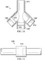
- the system 100 further includes a valve 132 placed over the aperture and a bridge manifold 136 positioned over the three valves 132 and dressings 114.
- Each valve 132 may be sealingly attached to the corresponding sealing member 118 such that any fluid communication with the tissue site 102 must be routed through the valve 132.
- the bridge manifold 136 is similar in function to the manifold 116 described previously in that the bridge manifold 136 provides a manifolding capability. Indeed, the bridge manifold 136 may be made from any of the materials previously listed for manifold 116.
- the reduced pressure supplied to the bridge manifold 136 may be distributed to each of the tissue sites 102, thereby removing fluids from each tissue site 102 and allowing the tissue site 102 to be exposed to a reduced pressure.
- a bridge cover 144 is positioned over the bridge manifold 126 and is sealed along a periphery of the bridge cover 144 to either the sealing member 118, the epidermis 108 of the patient, or in some instances both.
- the bridge cover 144 provides a substantially sealed space 146 within which the bridge manifold 136 resides. The presence of the bridge cover 144 allows the bridge manifold 136 to properly distribute fluids and pressures.
- An aperture 148 is positioned in the bridge cover 144 to provide fluid communication with the sealed space 146. While the aperture 148 is illustrated in FIG. 1 as being positioned over the right-most tissue site 102, the aperture 148 may instead be positioned over any particular tissue site 102, or alternatively may be positioned intermediately between two tissue sites.
- a reduced-pressure adapter 152 is positioned over the bridge cover 144 and is fluidly connected to the sealed space 146 through the aperture 148.
- a separate cover 154 may be provided to seal the fluid connection between the reduced-pressure adapter 152 and the sealed space 146.
- the reduced-pressure adapter 152 may be any device for delivering reduced pressure to the sealed space 148.
- the reduced-pressure adapter 152 may comprise one of the following: a T.R.A.C. ® Pad or Sensa T.R.A.C. ® Pad available from KCI of San Antonio, Texas; or another device or tubing.
- a multi-lumen reduced-pressure delivery tube 156 or conduit is fluidly coupled to the reduced-pressure adapter 152.
- the multi-lumen reduced-pressure delivery tube 156 has a first end 157 and a second end 159.
- the first end 157 of the multi-lumen reduced-pressure delivery tube 156 is fluidly coupled to a therapy unit 158.
- the multi-lumen reduced-pressure delivery tube 156 includes at least one pressure-sampling lumen and at least one reduced-pressure-supply lumen.
- the pressure-sampling lumen provides a pressure for determining the approximate pressure within the sealed space 148, which may approximate the pressure at each tissue site 102.
- the reduced-pressure-supply lumen delivers the reduced pressure to the reduced-pressure dressings 114 and receives fluids therefrom.
- the second end 159 of the multi-lumen reduced-pressure delivery tube 156 is fluidly coupled to the reduced-pressure adapter 152.
- the therapy unit 158 includes a fluid containment member 162 in fluid communication with a reduced pressure source 164.
- the fluid containment member 162 is a collection canister that includes a chamber for collecting fluids from the tissue site 102.
- the fluid containment member 162 alternatively could be an absorbent material or any other container, device, or material that is capable of collecting fluid.
- the reduced pressure source 164 may be an electrically-driven vacuum pump. In another implementation, the reduced pressure source 164 instead may be a manually-actuated or manually-charged pump that does not require electrical power. In one embodiment, the reduced pressure source 164 may be one or more piezoelectric-actuated micropumps that may be positioned remotely from the dressings 114, or adjacent the dressings 114. The reduced pressure source 164 instead may be any other type of pump, or alternatively a wall suction port or air delivery port such as those available in hospitals and other medical facilities.
- the reduced pressure source 164 may be housed within or used in conjunction with the therapy unit 158, which may also contain sensors, processing units, alarm indicators, memory, databases, software, display units, and user interfaces 166 that further facilitate the application of reduced pressure treatment to the tissue sites 102.
- pressure-detection sensors may be disposed at or near the reduced pressure source 164.
- the pressure-detection sensors may receive pressure data from the reduced-pressure adapter 152 via pressure-sampling lumens in the multi-lumen reduced-pressure delivery tube 156.
- the pressure-detection sensors may communicate with a processing unit that monitors and controls the reduced pressure that is delivered by the reduced pressure source 164.
- the reduced pressure will typically be between about -5 mmHg (-667 Pa) and about -500 mmHg (-66.7 kPa) and more typically between about -75 mmHg (-9.9 kPa) and about -300 mmHg (-39.9 kPa).
- the reduced-pressure source 164 may be a V.A.C. Freedom, V.A.C. ATS, InfoVAC, ActiVAC, AbThera or V.A.C. Ulta therapy unit available through Kinetic Concepts, Inc. of San Antonio, Texas.
- Valve 210 includes a valve body 214 and a valve lid 218 that are preferably formed from a polymer material, a metal, or any other material that is capable of providing a durable housing for a valve.
- the valve body 214 and valve lid 218 are capable of being coupled together to form an inner chamber 222.
- the inner chamber 222 is defined by an inlet wall 226 and an outlet wall 230.
- the valve body 214 includes at least one inlet port 238, and the valve lid 218 includes at least one outlet port 242.
- a sealing ring 250 is disposed on the inlet wall 226 and preferably surrounds the inlet port 238.
- sealing ring 250 may be an integral part of the inlet wall 226 and made from the same material as the inlet wall 226, the sealing ring 250 instead may be made from a different material that is over-molded or otherwise coupled to the inlet wall 226.
- the sealing ring 250 may be an elastomeric or other flexible material that is bonded or otherwise coupled to the inlet wall 226.
- Valve 210 further includes a valve flap 260 having a perimeter region 264 and a central region 268.
- the valve flap 260 may be made from a polymer or metal material, or any material that is capable of cooperating with the sealing ring 250 to control fluid flow through the valve 210.
- the valve flap 260 is positioned within the inner chamber 222 such that the perimeter region 264 of the valve flap 260 contacts the sealing ring 250.
- the central region 268 of the valve flap 260 is bonded or otherwise coupled to the inlet wall 226. While the valve flap 260 may be preformed in the curved configuration illustrated in FIGS. 2 and 3 , the coupling of the valve flap 260 to the inlet wall 226 preferably requires elastic deformation of the valve flap 260. This elastic deformation of the valve flap 260 will pre-stress the valve flap 260, which creates a better seal between the valve flap 260 and the sealing ring 250.
- valve flap 260 and thus the valve 210, is illustrated in a closed position in FIG. 2 .
- the valve flap 260 In the closed position, the valve flap 260 remains in contact with the sealing ring 250, and this contact substantially prevents fluid flow through the valve 210.
- FIG. 3 the valve flap 260, and thus the valve 210, is illustrated in an open position. In the open position, the valve flap 260 is elastically deformed and no longer contacts the sealing ring 250. While the valve flap 260 is open, fluid flow is permitted through the valve 210.
- movement of the valve flap 260 to an open position occurs when the pressure of fluid at the inlet port 238 is greater than the pressure of fluid at the outlet port 242.
- This favorable pressure differential is capable of moving the valve flap 260 away from the sealing ring 250 to allow fluid flow from the inlet port 238 to the outlet port 242.
- the fluid exerts a biasing force on the valve flap 260 to maintain contact with the sealing ring 250.
- This contact with the sealing ring 250 substantially prevents fluid flow from the outlet port 242 to the inlet port 238.
- the continued ability of the valve flap 260 to open and close is provided by the ability of the valve flap 260 to elastically deform. This elastic deformation may be provided by the material properties and physical dimensions (i.e. thickness) of the valve flap 260.
- sealing ring 250 is preferably continuously disposed around the at least one inlet port 238, the word "ring” is not meant to imply that the sealing ring 250 is limited to a circular shape.
- the sealing ring 250 could be any particular shape that is capable of fluidly isolating the inlet port 238 from the outlet port 242 when the valve flap 260 is in contact with the sealing ring 250.
- the valve 210 may be used with the system 100 of FIG. 1 , or any other reduced pressure treatment system, to prevent flow of fluid to a tissue site. In this manner, the valve 210 assists in preventing cross-contamination between tissue sites when multiple tissue sites are connected in serial fashion to a common reduced pressure source. Similarly, the valve 210 is capable of preventing backflow of fluid removed from a single tissue site when pressure changes may momentarily result in a differential pressure that attempts to push fluid back to the tissue site.
- the valve 210 may be placed adjacent a dressing similar to the placement of valves 132 relative to dressings 114 (see FIG. 1 ), or alternatively the valve 210 may be operably positioned relative to other system components as described herein.
- the valve 210 will typically be oriented such that the inlet port 238 is closer to the tissue site and the outlet port 242 is closer to the reduced pressure source.
- valve 210 may be configured to simply provide directional flow control similar to a check valve. In such a configuration, the force required to move the valve flap 260 from the closed position to the open position is relatively small. More specifically, a relatively low pressure differential across the valve flap 260 that favors flow in a direction toward the outlet port 242 would be capable of moving the valve flap 260 to the open position. In this same configuration, a relatively low pressure differential across the valve flap 260 that favors flow in a direction toward the inlet port 238 would keep the valve flap 260 in the closed position.
- valve flap 260 may be configured to require a higher differential pressure to move to the open position.
- the valve 210 By increasing the differential pressure required to open the valve flap 260, the valve 210 essentially becomes a regulating valve with a required "cracking pressure" to open the valve. This cracking pressure ensures that a reduced pressure reaches a particular level (i.e. that the absolute pressure be low enough) in order for the valve to open.
- Valve 410 includes a valve body 414 and a valve lid 418 that are preferably formed from a polymer material, a metal, or any other material that is capable of providing a durable housing for a valve.
- the valve body 414 and valve lid 418 are capable of being coupled together to form an inner chamber 422.
- the inner chamber 422 is defined by an inlet wall 426 and an outlet wall 430.
- the valve body 414 includes at least one inlet port 438, and the valve lid 418 includes at least one outlet port 442.
- a sealing ring 450 is disposed on the inlet wall 426 and preferably surrounds the inlet port 438.
- sealing ring 450 may be an integral part of the inlet wall 426 and made from the same material as the inlet wall 426, the sealing ring 450 instead may be made from a different material that is over-molded or otherwise coupled to the inlet wall 426. In one embodiment, the sealing ring 450 may be an elastomeric or other flexible material that is bonded or otherwise coupled to the inlet wall 426.
- Valve 410 further includes a valve flap 460 having a perimeter region 464 and a central region 468.
- the valve flap 460 and the operation of valve 410 is essentially the same as valve 210 illustrated in FIGS. 2 and 3 .
- the valve flap 460 is positioned within the inner chamber 422 such that the perimeter region 464 of the valve flap 460 contacts the sealing ring 450.
- the central region 468 of the valve flap 460 contacts the inlet wall 426, but unlike valve 210, the valve flap 460 is not bonded or coupled to the inlet wall 426. Instead, at least one projection 470 extends from the valve lid 418.
- valve flap 460 When the valve lid 418 and valve body 414 are assembled, the projection 470 exerts a force on the valve flap 460 to bias the valve flap 460 into contact with the inlet wall 426. Once again, this elastic deformation of the valve flap 460 pre-stresses the valve flap 460, which creates a better seal between the valve flap 460 and the sealing ring 450.
- the valve flap 460 and thus the valve 410 is illustrated in a closed position in FIG. 4 .
- the valve 410 operates in a manner similar to that described for valve 210, and the valve 410 may be used with the system 100 of FIG. 1 , or any other reduced pressure treatment system, to prevent flow of fluid to a tissue site. In this manner, the valve 410 assists in preventing cross-contamination between tissue sites when multiple tissue sites are connected in serial fashion to a common reduced pressure source. Similarly, the valve 410 is capable of preventing backflow of fluid removed from a single tissue site when pressure changes may momentarily result in a differential pressure that attempts to push fluid back to the tissue site.
- the valve 410 may be placed adjacent a dressing similar to the placement of valves 132 relative to dressings 114 (see FIG. 1 ), or alternatively the valve 410 may be operably positioned relative to other system components as described herein.
- the valve 410 will typically be oriented such that the inlet port 438 is closer to the tissue site and the outlet port 442 is
- Movement of the valve flap 460 is dependent on the differential pressure across the valve flap 460.
- the valve 410 may be configured to simply provide directional flow control similar to a check valve. In such a configuration, the force required to move the valve flap 460 from the closed position to the open position is relatively small. More specifically, a relatively low pressure differential across the valve flap 460 that favors flow in a direction toward the outlet port 442 would be capable of moving the valve flap 460 to the open position. In this same configuration, a relatively low pressure differential across the valve flap 460 that favors flow in a direction toward the inlet port 438 would keep the valve flap 460 in the closed position.
- the valve flap 460 may be configured to require a higher differential pressure to move into the open position.
- the valve 410 By increasing the differential pressure required to open the valve flap 460, the valve 410 essentially becomes a regulating valve with a required "cracking pressure" to open the valve. This cracking pressure ensures that a reduced pressure reaches a particular level (i.e. that the absolute pressure be low enough) in order for the valve 410 to open.
- Valve 510 includes a valve body 514 and a valve lid 518 that are preferably formed from a polymer material, a metal, or any other material that is capable of providing a durable housing for a valve.
- the valve body 514 and valve lid 518 are capable of being coupled together to form an inner chamber 522.
- the inner chamber 522 is defined by an inlet wall 526 and an outlet wall 530.
- the valve body 514 includes at least one inlet port 538, and the valve lid 518 includes at least one outlet port 542.
- a sealing member 550 is disposed on the inlet wall 526 and preferably surrounds the inlet port 538.
- the sealing member 550 is preferably configured in the shape of a duck-bill valve or control device and includes a pair of flappers 560 that are urged together when the valve 510 is in a closed position (see FIG. 5 ).
- the flappers 560 may be urged together by the shape and elasticity characteristics of the flappers 560.
- the flappers 560 may be urged together by a biasing member or spring device disposed internal or external to the sealing member 550.
- the flappers 560 and the operation of valve 510 is similar to the operation of valves 210 and 410 illustrated in FIGS. 2-4 .
- the valve 510 may be used with the system 100 of FIG. 1 , or any other reduced pressure treatment system, to prevent flow of fluid to a tissue site. In this manner, the valve 510 assists in preventing cross-contamination between tissue sites when multiple tissue sites are connected in serial fashion to a common reduced pressure source. Similarly, the valve 510 is capable of preventing backflow of fluid removed from a single tissue site when pressure changes may momentarily result in a differential pressure that attempts to push fluid back to the tissue site.
- the valve 510 may be placed adjacent a dressing similar to the placement of valves 132 relative to dressings 114 (see FIG. 1 ), or alternatively the valve 510 may be operably positioned relative to other system components as described herein.
- the valve 510 will typically be oriented such that the inlet port 538 is closer to the tissue site and the outlet port 542 is closer to the reduced pressure source.
- Movement of the flappers 560 is dependent on the differential pressure across the sealing member 550.
- the valve 510 may be configured to simply provide directional flow control similar to a check valve. In such a configuration, the force required to separate the flappers 560 (i.e. move the flappers 560 to an open position) is relatively small. More specifically, a relatively low pressure differential across the sealing member 550 that favors flow in a direction toward the outlet port 542 would be capable of moving the flappers 560 to the open position. In this same configuration, a relatively low pressure differential across the sealing member 550 that favors flow in a direction toward the inlet port 538 would keep the flappers 560 in the closed position.
- the flappers 560 may be configured to require a higher differential pressure to move into the open position.
- the valve 510 By increasing the differential pressure required to open the flappers 560, the valve 510 essentially becomes a regulating valve with a required "cracking pressure" to open the valve. This cracking pressure ensures that a reduced pressure reaches a particular level (i.e. that the absolute pressure be low enough) in order for the valve 510 to open.
- Valve 610 includes a valve body 614 and a valve lid 618 that are preferably formed from a polymer material, a metal, or any other material that is capable of providing a durable housing for a valve.
- the valve body 614 and valve lid 618 are capable of being coupled together to form an inner chamber 622.
- the inner chamber 622 is defined by an inlet wall 626 and an outlet wall 630.
- the valve body 614 includes at least one inlet port 638, and the valve lid 618 includes at least one outlet port 642.
- a sealing ring 650 is disposed on the inlet wall 626 and preferably surrounds the inlet port 638.
- sealing ring 650 may be an integral part of the inlet wall 626 and made from the same material as the inlet wall 626, the sealing ring 650 instead may be made from a different material that is over-molded or otherwise coupled to the inlet wall 626. In one embodiment, the sealing ring 650 may be an elastomeric or other flexible material that is bonded or otherwise coupled to the inlet wall 626.
- Valve 610 further includes a valve flap 660 having a perimeter region 664 and a central region 668.
- the valve flap 660 and the operation of valve 610 is somewhat similar to the operation of valve 210 illustrated in FIGS. 2 and 3 .
- the valve flap 660 is positioned within the inner chamber 622 such that the perimeter region 664 of the valve flap 660 contacts the sealing ring 650.
- valve flap 660 is not elastically deformed into a curved shape such that the central region 668 of the valve flap 660 contacts the inlet wall 626. Instead, valve flap 660 is made from a more rigid material and remains in a substantially planar configuration.
- the valve flap 660 is biased into contact with the sealing ring 650 in the closed position (not shown) by a spring 672.
- the force exerted by the spring 672 on the valve flap 660 may be adjusted by varying the distance, D, that the spring is pre-compressed.
- a shaft 676 and adjustment member 682 permit the distance D to be adjusted, which results in the adjustability of the force required to move the valve flap 660 to the open position (see FIG. 6 ).
- the valve 610 operates in a manner similar to that described for valve 210, and the valve 610 may be used with the system 100 of FIG. 1 , or any other reduced pressure treatment system, to prevent flow of fluid to a tissue site. In this manner, the valve 610 assists in preventing cross-contamination between tissue sites when multiple tissue sites are connected in serial fashion to a common reduced pressure source. Similarly, the valve 610 is capable of preventing backflow of fluid removed from a single tissue site when pressure changes may momentarily result in a differential pressure that attempts to push fluid back to the tissue site.
- the valve 610 may be placed adjacent a dressing similar to the placement of valves 132 relative to dressings 114 (see FIG. 1 ), or alternatively the valve 610 may be operably positioned relative to other system components as described herein.
- the valve 610 will typically be oriented such that the inlet port 638 is closer to the tissue site and the outlet port 642 is closer to the reduced pressure source.
- Movement of the valve flap 660 is dependent on the differential pressure across the valve flap 660.
- the valve 610 may be configured to simply provide directional flow control similar to a check valve. In such a configuration, the force required to move the valve flap 660 from the closed position to the open position is relatively small. More specifically, a relatively low pressure differential across the valve flap 660 that favors flow in a direction toward the outlet port 642 would be capable of moving the valve flap 660 to the open position. In this same configuration, a relatively low pressure differential across the valve flap 660 that favors flow in a direction toward the inlet port 638 would keep the valve flap 660 in the closed position. In another embodiment, the valve flap 660 may be configured to require a higher differential pressure to move into the open position.
- the valve 610 By increasing the differential pressure required to open the valve flap 660, the valve 610 essentially becomes a regulating valve with a required "cracking pressure" to open the valve. This cracking pressure ensures that a reduced pressure reaches a particular level (i.e. that the absolute pressure be low enough) in order for the valve 610 to open.
- valve configurations have been described to regulate pressure or control the direction of fluid flow, it should be recognized that other valve configurations may be used with the reduced pressure treatment systems described herein.
- Other valve configurations may include, without limitation, ball valves, poppet valves, gate valves, or butterfly valves.
- a reduced pressure treatment system 700 includes a valve 710 positioned proximate a reduced-pressure dressing 714 positioned at a tissue site 702.
- the reduced-pressure dressing 714 includes a manifold 716 and a sealing member or cover 718.
- the cover 718 is releasably coupled to the patient 704 using adhesive or other coupling means.
- the cover 718 includes an aperture 728, and the valve 710 is positioned above the cover 718 such that the valve 710 covers the aperture 728.
- valve 710 is bonded, welded, or otherwise sealingly attached to the cover 718 such that fluids exiting the space beneath the cover 718 must pass through the valve 710. While the valve 710 is illustrated above the cover 718 in FIG. 7 , the valve 710 instead may be installed beneath the cover 718 as long as the means of attachment provides the desired seal between the valve 710 and cover 718.
- the valve 710 may include an adhesive or other bonding agent disposed on one of the surfaces of the valve 710 to allow the valve 710 to be attached to the cover 718. In another embodiment, the adhesive or bonding agent may be disposed on the cover 718.
- a bridge manifold 736 Positioned above the valve 710 is a bridge manifold 736 similar to the bridge manifold 136 of system 100.
- the bridge manifold 736 provides a common means of fluid communication between multiple tissue sites, or in some circumstances, provides the ability to manifold reduced pressure from a remote location. Placement of the valve 710 in sealed contact with the cover 718 and below the bridge manifold 736 allows the valve 710 to substantially prevent fluids in the bridge manifold 736 from entering the sealed space beneath the cover 718.
- the placement of the valve 710, or any of the valves described herein, adjacent a reduced pressure dressing permits directional control of fluids, and in some embodiments, control of pressures associated with tissue sites undergoing reduced pressure treatment.
- a reduced-pressure adapter 852 similar to reduced-pressure adapter 152 of system 100, includes a conduit housing 874 having a recessed region 876 defining an entry surface 878.
- a primary conduit 880 is positioned within the conduit housing 874.
- the reduced-pressure adapter 852 further includes a base 884 attached to the conduit housing 874 such that an aperture of the base 884 surrounds the recessed region 876.
- the reduced pressure adapter 852 provides an interface between a reduced pressure source and a reduced-pressure dressing.
- the valve 810 is disposed between the primary conduit 880 and the recessed region 876 such that an inlet of the valve 810 is oriented toward the recessed region 876 and an outlet of the valve 810 is oriented toward the primary conduit 880.
- the placement of the valve 810 relative to the various components of the reduced-pressure adapter 852 may vary; however, it is desired that the valve 810 be arranged such that any fluids passing through the reduced-pressure adapter 852 be required to pass through the valve 810 and be subject to control by the valve 810.
- the valve 810 may be permanently or removably installed relative to the reduced-pressure adapter 852.
- tissue site 902 may be the bodily tissue of any human, animal, or other organism, including bone tissue, adipose tissue, muscle tissue, dermal tissue, vascular tissue, connective tissue, cartilage, tendons, ligaments, or any other tissue.
- Treatment of tissue sites 902 may include removal of fluids, e.g., exudate or ascites. While numerous tissue sites, sizes, and depths may be treated with the system 900, the system 900 may, for example, be utilized to treat wounds (not shown).
- a wound may, for example, extend through epidermis 908, dermis 990, and into subcutaneous tissue 912. Other depths or type of wounds, or more generally, tissue sites may be treated. While three tissue sites 902 are shown for illustration purposes, it should be understood that any number of tissue sites may be treated with the system 900.
- the system 900 includes a plurality of reduced-pressure dressings 914 deployed on the plurality of tissue sites 902.
- Each of the plurality of reduced-pressure dressings 914 may be any kind of dressing that allows reduced pressure to be delivered to the tissue site 902 and that is operable to remove fluids from the tissue site 902.
- each reduced-pressure dressing 914 includes a dressing filler, or manifold 916, and a sealing member 918.
- the sealing member 918 is releasably coupled to the patient 904 using an attachment device 922.
- the attachment device 922 may take numerous forms.
- the attachment device 922 may be a medically acceptable, pressure-sensitive adhesive that extends about a periphery or a portion of the entire sealing member 918, a double-sided drape tape, a paste, a hydrocolloid, a hydrogel, or other sealing devices or elements.
- the sealing member 918 creates a substantially sealed space 924 containing the manifold 916 and the tissue site 902 to be treated.
- the manifold 916 is a substance or structure that is provided to assist in applying reduced pressure to, delivering fluids to, or removing fluids from the associated tissue site 902.
- the manifold 916 includes a plurality of flow channels or pathways that are capable of distributing fluids provided to or removed from the tissue site 902 around the manifold 916.
- the flow channels or pathways are interconnected to improve distribution of fluids provided to or removed from the tissue site 902.
- the manifold 916 comprises one or more of the following: a biocompatible material that is capable of being placed in contact with the tissue site 902 and distributing reduced pressure to the tissue site 902; devices that have structural elements arranged to form flow channels, such as, for example, cellular foam, open-cell foam, porous tissue collections, liquids, gels, and foams that include, or cure to include, flow channels; porous materials, such as foam, gauze, felted mats, or any other material suited to a particular biological application; or porous foam that includes a plurality of interconnected cells or pores that act as flow channels, e.g., a polyurethane, open-cell, reticulated foam such as GranuFoam® material manufactured by Kinetic Concepts, Incorporated of San Antonio, Texas; a bioresorbable material; or a scaffold material.
- a biocompatible material that is capable of being placed in contact with the tissue site 902 and distributing reduced pressure to the tissue site 902
- devices that have structural elements arranged to form flow channels
- the manifold 916 may also be used to distribute fluids such as medications, antibacterials, growth factors, and various solutions to the tissue site 902.
- Other layers may be included in or on the manifold 916, such as absorptive materials, wicking materials, hydrophobic materials, and hydrophilic materials.
- the manifold 916 may be constructed from a bioresorbable material that may remain in a patient's body following use of the reduced-pressure dressing 914.
- Suitable bioresorbable materials may include, without limitation, a polymeric blend of polylactic acid (PLA) and polyglycolic acid (PGA).
- the polymeric blend may also include without limitation polycarbonates, polyfumarates, and capralactones.
- the manifold 916 may further serve as a scaffold for new cell-growth, or a scaffold material may be used in conjunction with the manifold 916 to promote cell-growth.
- a scaffold is a substance or structure used to enhance or promote the growth of cells or formation of tissue, such as a three-dimensional porous structure that provides a template for cell growth.
- Illustrative examples of scaffold materials include calcium phosphate, collagen, PLA/PGA, coral hydroxy apatites, carbonates, or processed allograft materials.
- the sealing member 918 may be any material that provides a fluid seal.
- a fluid seal is a seal adequate to maintain reduced pressure at a desired site given the particular reduced-pressure source or subsystem involved.
- the sealing member 918 may be, for example, an impermeable or semi-permeable, elastomeric material. For semi-permeable materials, the permeability must be low enough that for a given reduced-pressure source, the desired reduced pressure may be maintained.
- the sealing member 918 may be discrete pieces for each reduced-pressure dressing 914 or may be one continuous sheet used for all the plurality of reduced-pressure dressings 914.
- a reduced-pressure adapter 952 is coupled to each sealing member 918 such that the reduced-pressure adapter 952 allows fluid communication with the sealed space 924 beneath each sealing member 918.
- the reduced-pressure adapter 952 may be any device for delivering reduced pressure to the sealed space 924.
- the reduced-pressure adapter 952 may comprise one of the following: a T.R.A.C. ® Pad or Sensa T.R.A.C. ® Pad available from KCI of San Antonio, Texas; or another device or tubing.
- a multi-lumen reduced-pressure delivery tube 956 or conduit is fluidly coupled to each reduced-pressure adapter 952.
- the multi-lumen reduced-pressure delivery tube 956 has a first end 957 and a second end 959.
- the first end 957 of the multi-lumen reduced-pressure delivery tube 956 is fluidly coupled to a multi-path connector 961.
- the multi-path connector 961 illustrated in FIG. 9 includes four connection ports, one for receiving each of the reduced-pressure delivery tubes 956 and one for receiving a supply tube 963 fluidly connected between the multi-path connector 961 and a therapy unit 958.
- Each multi-lumen reduced-pressure delivery tube 956 may include at least one pressure-sampling lumen and at least one reduced-pressure-supply lumen.
- the pressure-sampling lumen provides a pressure for determining the approximate pressure within the sealed space 924, which may approximate the pressure at each tissue site 902.
- the reduced-pressure-supply lumen delivers the reduced pressure to the reduced-pressure dressings 914 and receives fluids therefrom.
- the second end 959 of the multi-lumen reduced-pressure delivery tube 956 is fluidly coupled to the reduced-pressure adapter 952.
- the therapy unit 958 includes a fluid containment member 962 in fluid communication with a reduced pressure source 964.
- the fluid containment member 962 is a collection canister that includes a chamber for collecting fluids from the tissue site 902.
- the fluid containment member 962 alternatively could be an absorbent material or any other container, device, or material that is capable of collecting fluid.
- the reduced pressure source 964 may be an electrically-driven vacuum pump. In another implementation, the reduced pressure source 964 instead may be a manually-actuated or manually-charged pump that does not require electrical power. In one embodiment, the reduced pressure source 964 may be one or more piezoelectric-actuated micropumps that may be positioned remotely from the dressings 914, or adjacent the dressings 914. The reduced pressure source 964 instead may be any other type of pump, or alternatively a wall suction port or air delivery port such as those available in hospitals and other medical facilities.
- the reduced pressure source 964 may be housed within or used in conjunction with the therapy unit 958, which may also contain sensors, processing units, alarm indicators, memory, databases, software, display units, and user interfaces 966 that further facilitate the application of reduced pressure treatment to the tissue sites 902.
- pressure-detection sensors may be disposed at or near the reduced pressure source 964.
- the pressure-detection sensors may receive pressure data from the reduced-pressure adapter 952 via pressure-sampling lumens in the multi-lumen reduced-pressure delivery tube 956.
- the pressure-detection sensors may communicate with a processing unit that monitors and controls the reduced pressure that is delivered by the reduced pressure source 964.
- the reduced pressure will typically be between about -5 mmHg (-667 Pa) and about -500 mmHg (-66.7 kPa) and more typically between about -75 mmHg (-9.9 kPa) and about -300 mmHg (-39.9 kPa).
- the reduced-pressure source 964 may be a V.A.C. Freedom, V.A.C. ATS, InfoVAC, ActiVAC, AbThera or V.A.C. Ulta therapy unit available through Kinetic Concepts, Inc. of San Antonio, Texas.
- the system 900 further includes a valve 910 associated with the fluid communication paths located between each tissue site 902 and the reduced pressure source 964.
- the valve 910 (more specifically designated 910a) is positioned in line with the reduced-pressure delivery tube 956.
- the valves 910 are positioned within the multi-path connector 957.
- Each valve 910 may provide directional fluid control to prevent fluid from flowing to the tissue sites 902.
- the valves 910 are provided to regulate the amount of reduced pressure provided to the tissue sites 902.
- the multi-path connector 1061 is similar to multi-path connector 961 and includes a first branch port 1065, a second branch port 1067, a third branch port 1069, and a supply port 1071.
- Each of the branch ports 1065, 1067, 1069 is adapted to be coupled to a reduced-pressure tube that is fluidly connected to a reduced-pressure dressing.
- the supply port 1071 is adapted to be coupled to a supply tube that is fluidly connected to a reduced pressure source.
- the multi-path connector 1061 provides a means of connecting multiple tubes or conduits so that fluid and pressure distribution may occur. While the multi-path connector 1061 illustrated in FIG. 10 is capable of fluidly connecting four conduits or tubes, a connector could instead by provided that connects a fewer number of tubes or a greater number of tubes.
- a valve 1010 is disposed within each of the branch ports 1065, 1067, 1069.
- the placement of the valves 1010 relative to the various ports of the multi-path connector 1061 may vary; however, it is desired that the valve 1010 be arranged such that any fluids passing through the multi-path connector 1061 be required to pass through the valves 1010 and be subject to control by the valves 1010.
- the valve 1010 may be permanently or removably installed relative to the multi-path connector 1061.
- a reduced-pressure delivery tube 1126 is presented.
- the reduced-pressure delivery tube 1126 is similar to reduced-pressure delivery tube 956 and preferably provides fluid communication between a reduced pressure source and a reduced-pressure dressing.
- a valve 1110 is operably associated with the reduced-pressure delivery tube 1126.
- the particular placement of the valve 1110 within or simply connected to the tube may vary; however, it is desired that the valve 1110 be arranged such that any fluids passing through the reduced-pressure delivery tube 1126 be required to pass through the valve 1110 and be subject to control by the valve 1110.
- the valve 1110 may be permanently or removably installed relative to the reduced-pressure delivery tube 1126.
Claims (10)
- Système pour traiter plusieurs sites tissulaires, comprenant :- une première garniture de pansement (116, 916) adaptée à être positionnée au niveau d'un premier des sites tissulaires ;- une seconde garniture de pansement (116, 916) adaptée à être positionnée au niveau d'un second des sites tissulaires ;- une source de pression réduite (164, 964) adaptée à être reliée de manière fluidique à la première garniture de pansement (116, 916) et à la seconde garniture de pansement (116, 916) ; caractérisé par- un collecteur en pont (136, 736) adapté à assurer une communication de fluide entre la première garniture de pansement (116, 916) et la seconde garniture de pansement (116, 916), la source de pression réduite (164, 964) étant adaptée à être couplée de manière fluidique à la première garniture de pansement (116, 916) et à la seconde garniture de pansement (116, 916) via le collecteur en pont (136, 736) ;- une première valve (132, 710, 910) adaptée à être associée au premier site tissulaire (102, 902) pour permettre au fluide de s'écouler depuis le premier site tissulaire (102, 902) et pour empêcher sensiblement l'écoulement de fluide vers le premier site tissulaire (102, 902) ; et- une seconde valve (132, 710, 910) adaptée à être associée au second site tissulaire (102, 902) pour permettre au fluide de s'écouler depuis le second site tissulaire (102, 902) et pour empêcher sensiblement l'écoulement de fluide vers le second site tissulaire (102, 902).
- Système selon la revendication 1, dans lequel une communication de fluide avec la première garniture de pansement (116, 916) est fournie via la première valve (132, 710, 910) et une communication de fluide avec la seconde garniture de pansement (116, 916) est fournie via la seconde valve (132, 710, 910).
- Système selon la revendication 2, la première valve (132, 710, 910) et la seconde valve (132, 710, 910) ayant chacune une entrée et une sortie, la première valve (132, 710, 910) et la seconde valve (132, 710, 910) adaptées chacune à assurer une communication de fluide depuis l'entrée vers la sortie et pour empêcher sensiblement la communication de fluide depuis la sortie vers l'entrée, dans lequel l'entrée de la première valve (132, 710, 910) est positionnée en direction de la première garniture de pansement (116, 916) et l'entrée de la seconde valve (132, 710, 910) est positionnée en direction de la seconde garniture de pansement (116, 916).
- Système selon la revendication 3, dans lequel la première valve (132, 710, 910) et la seconde valve (132, 710, 910) comportent chacune un clapet de valve (260, 460, 660) et une bague d'étanchéité (250, 450, 650) positionnés en communication de fluide entre l'entrée et la sortie, dans lequel le clapet de valve (260, 460, 660) peut être déplacé entre une position fermée et une position ouverte, et dans lequel en position fermée le clapet de valve (260, 460, 660) vient en contact de la bague d'étanchéité (250, 450, 650) empêchant sensiblement la communication de fluide entre l'entrée et la sortie, et dans lequel en position ouverte le clapet de valve (260, 460, 660) est séparé de la bague d'étanchéité (250, 450, 650) permettant la communication de fluide entre l'entrée et la sortie.
- Système selon la revendication 1, caractérisé en ce que la première valve (132, 710, 910) est positionnée en communication de fluide entre le collecteur en pont (136, 736) et la première garniture de pansement (116, 916) et la seconde valve (132, 710, 910) est positionnée en communication de fluide entre le collecteur en pont (136, 736) et la seconde garniture de pansement (116, 916).
- Système selon la revendication 1, comprenant en outre un premier couvercle et un second couvercle, le premier couvercle étant adapté à être positionné de façon adjacente à la première garniture de pansement (116, 916) pour fournir un espace sensiblement étanche entre le premier couvercle et le premier site tissulaire, le second couvercle étant adapté à être positionné de manière adjacente à la seconde garniture de pansement (116, 916) pour fournir un espace sensiblement étanche entre le second couvercle et le second site tissulaire.
- Système selon la revendication 6, dans lequel la première valve (132, 710, 910) est fixée de manière étanche au premier couvercle et la seconde valve (132, 710, 910) est fixée de manière étanche au second couvercle.
- Système selon la revendication 6, comprenant en outre un adaptateur adapté à coupler fluidiquement un conduit au premier couvercle, dans lequel la première valve (132, 710, 910) est logée dans l'adaptateur et est adaptée à être positionnée en communication de fluide entre le conduit et le premier couvercle.
- Système pour traiter une pluralité de sites tissulaires selon la revendication 1, dans lequel :- la première valve est en communication de fluide entre le collecteur en pont et la première garniture de pansement (116, 916) ;- la seconde valve est en communication de fluide entre le collecteur en pont et la seconde garniture de pansement (116, 916), dans lequel une communication de fluide avec la seconde garniture de pansement (116, 916) est fournie via la seconde valve, et dans lequel une entrée de la première valve est positionnée en direction de la première garniture de pansement (116, 916) et une entrée de la seconde valve est positionnée en direction de la seconde garniture de pansement (116, 916).
- Système selon la revendication 9, caractérisé en ce que la première valve et la seconde valve comportent chacune un clapet de valve (260, 460, 660) et une bague d'étanchéité disposés en communication de fluide entre l'entrée et la sortie, dans laquelle le clapet de valve (260, 460, 660) peut être déplacé entre une position fermée et une position ouverte, et dans lequel en position fermée le clapet de valve (260, 460, 660) est en contact avec la bague d'étanchéité (250, 450, 650) empêchant sensiblement la communication de fluide entre l'entrée et la sortie, et dans lequel en position ouverte le clapet de valve (260, 460, 660) est séparé de la bague d'étanchéité (250, 450, 650) permettant une communication de fluide entre l'entrée et la sortie.
Priority Applications (1)
| Application Number | Priority Date | Filing Date | Title |
|---|---|---|---|
| EP17168662.9A EP3219338A3 (fr) | 2011-11-23 | 2012-11-16 | Systèmes et méthodes de traitement de tissus à pression réduite dans lesquels un pansement à pression réduite et une valve associée sont utilisés |
Applications Claiming Priority (2)
| Application Number | Priority Date | Filing Date | Title |
|---|---|---|---|
| US201161563529P | 2011-11-23 | 2011-11-23 | |
| PCT/US2012/065631 WO2013078095A2 (fr) | 2011-11-23 | 2012-11-16 | Systèmes et méthodes de traitement de tissus à pression réduite dans lesquels un pansement à pression réduite et une valve associée sont utilisés |
Related Child Applications (1)
| Application Number | Title | Priority Date | Filing Date |
|---|---|---|---|
| EP17168662.9A Division EP3219338A3 (fr) | 2011-11-23 | 2012-11-16 | Systèmes et méthodes de traitement de tissus à pression réduite dans lesquels un pansement à pression réduite et une valve associée sont utilisés |
Publications (2)
| Publication Number | Publication Date |
|---|---|
| EP2782614A2 EP2782614A2 (fr) | 2014-10-01 |
| EP2782614B1 true EP2782614B1 (fr) | 2017-05-03 |
Family
ID=47279101
Family Applications (2)
| Application Number | Title | Priority Date | Filing Date |
|---|---|---|---|
| EP17168662.9A Withdrawn EP3219338A3 (fr) | 2011-11-23 | 2012-11-16 | Systèmes et méthodes de traitement de tissus à pression réduite dans lesquels un pansement à pression réduite et une valve associée sont utilisés |
| EP12795246.3A Active EP2782614B1 (fr) | 2011-11-23 | 2012-11-16 | Systèmes et méthodes de traitement de tissus à pression réduite dans lesquels un pansement à pression réduite et une valve associée sont utilisés |
Family Applications Before (1)
| Application Number | Title | Priority Date | Filing Date |
|---|---|---|---|
| EP17168662.9A Withdrawn EP3219338A3 (fr) | 2011-11-23 | 2012-11-16 | Systèmes et méthodes de traitement de tissus à pression réduite dans lesquels un pansement à pression réduite et une valve associée sont utilisés |
Country Status (7)
| Country | Link |
|---|---|
| US (1) | US9981075B2 (fr) |
| EP (2) | EP3219338A3 (fr) |
| JP (1) | JP6158209B2 (fr) |
| CN (1) | CN103917257B (fr) |
| AU (1) | AU2012340921B2 (fr) |
| CA (1) | CA2855743A1 (fr) |
| WO (1) | WO2013078095A2 (fr) |
Families Citing this family (38)
| Publication number | Priority date | Publication date | Assignee | Title |
|---|---|---|---|---|
| US10413450B2 (en) * | 2007-12-12 | 2019-09-17 | University Of Kansas | Barrier system to reduce the rates of infections |
| DE102010034292A1 (de) * | 2010-08-13 | 2012-02-16 | Paul Hartmann Ag | Verbindungsvorrichtung zum Zusammenführen wenigstens zweier Leitungsabschnitte bei einem Unterdruckwundbehandlungssystem |
| EP3260144B1 (fr) * | 2012-09-12 | 2020-01-29 | KCI Licensing, Inc. | Systèmes de collecte d'exsudats en thérapie sous pression réduite |
| US9427503B2 (en) * | 2013-03-15 | 2016-08-30 | Corvivo Inc. | Cardiotomy suction tube system with multiple tips |
| JP6455515B2 (ja) * | 2014-07-08 | 2019-01-23 | 株式会社村田製作所 | 陰圧閉鎖治療装置 |
| US10702649B2 (en) * | 2014-07-24 | 2020-07-07 | Kci Licensing, Inc. | Combination fluid instillation and negative pressure dressing |
| CN104225770A (zh) * | 2014-09-30 | 2014-12-24 | 昆山韦睿医疗科技有限公司 | 一种多负压治疗设备的协同方法及负压治疗系统 |
| EP3714916A1 (fr) | 2015-07-29 | 2020-09-30 | Innovative Therapies Inc. | Système de surveillance et de contrôle de la pression des appareils de traitement des plaies |
| CN107920923A (zh) | 2015-08-31 | 2018-04-17 | 3M创新有限公司 | 包含对湿表面具有增强的粘附性的(甲基)丙烯酸酯压敏粘合剂的负压伤口治疗敷料 |
| WO2017040072A1 (fr) | 2015-08-31 | 2017-03-09 | 3M Innovative Properties Company | Articles comprenant un adhésif autocollant de (méth)acrylate présentant une adhésion améliorée sur des surfaces mouillées |
| GB201519388D0 (en) | 2015-11-03 | 2015-12-16 | I2R Medical Ltd | Connector |
| AU2017227923B2 (en) | 2016-03-04 | 2022-01-27 | Smith & Nephew Plc | Negative pressure wound therapy apparatus for post breast surgery wounds |
| US11413388B2 (en) * | 2016-05-24 | 2022-08-16 | Somavac Medical Solutions, Inc. | Portable device with disposable reservoir for collection of internal fluid after surgery from a plurality of sites simultaneously |
| US11577017B2 (en) | 2016-05-24 | 2023-02-14 | Somavac Medical Solutions, Inc. | Analytical method for controlled and measured internal fluid after surgery |
| ES2944940T3 (es) * | 2016-11-10 | 2023-06-27 | Moelnlycke Health Care Ab | Dispositivo conector para un sistema de terapia de heridas por presión negativa |
| CN106581789B (zh) * | 2016-12-12 | 2023-05-26 | 武汉维斯第医用科技股份有限公司 | 用于负压封闭引流系统的外部多管路转换器 |
| CN110709113A (zh) | 2017-02-15 | 2020-01-17 | 新加坡施乐辉有限公司 | 负压伤口治疗设备及其使用方法 |
| AU2018228663B2 (en) | 2017-02-28 | 2023-05-18 | T.J.Smith And Nephew, Limited | Multiple dressing negative pressure wound therapy system |
| GB2560365B (en) * | 2017-03-09 | 2021-10-20 | Brightwake Ltd | Improvements relating to apparatus negative pressure wound therapy |
| EP3372257A1 (fr) * | 2017-03-09 | 2018-09-12 | Mölnlycke Health Care AB | Ensemble de thérapie de plaies à pression négative |
| JP7162003B2 (ja) * | 2017-03-15 | 2022-10-27 | スミス アンド ネフュー ピーエルシー | 較正されたリーク経路を有する複数の被覆材陰圧創傷療法システム |
| CA3065521A1 (fr) * | 2017-06-07 | 2018-12-13 | Kci Licensing, Inc. | Pansement pour cavite de plaie multicouche pour duree d'utilisation prolongee |
| JP7155162B2 (ja) * | 2017-06-14 | 2022-10-18 | ティージェイ スミス アンド ネフュー リミテッド | 陰圧創傷療法装置 |
| WO2019055176A1 (fr) * | 2017-09-14 | 2019-03-21 | Kci Licensing, Inc. | Oxygénothérapie avec élimination de fluide |
| GB201813282D0 (en) * | 2018-08-15 | 2018-09-26 | Smith & Nephew | System for medical device activation and opertion |
| GB201804347D0 (en) | 2018-03-19 | 2018-05-02 | Smith & Nephew Inc | Securing control of settings of negative pressure wound therapy apparatuses and methods for using the same |
| BR112020019519A2 (pt) * | 2018-03-26 | 2020-12-29 | Deroyal Industries, Inc. | Sistema para facilitar a distribuição de pressão reduzida a um local de ferimento |
| CN108433747A (zh) * | 2018-04-11 | 2018-08-24 | 中山大学中山眼科中心 | 负压式液态标本的采集装置 |
| GB201806988D0 (en) | 2018-04-30 | 2018-06-13 | Quintanar Felix Clarence | Power source charging for negative pressure wound therapy apparatus |
| JP7469231B2 (ja) | 2018-04-30 | 2024-04-16 | スミス・アンド・ネフュー・アジア・パシフィク・ピーティーイー・リミテッド | デュアルモード陰圧創傷療法装置を制御するためのシステムおよび方法 |
| GB201808438D0 (en) | 2018-05-23 | 2018-07-11 | Smith & Nephew | Systems and methods for determining blockages in a negative pressure wound therapy system |
| JP7383695B2 (ja) * | 2018-08-29 | 2023-11-20 | アートラ・メディカル、エルエルシー | 機械式化学ポンプを具える陰圧処理 |
| WO2020231360A1 (fr) * | 2019-05-10 | 2020-11-19 | HOT, Semih | Système de fermeture assisté par dépression à deux voies |
| US11484640B2 (en) | 2019-07-03 | 2022-11-01 | T.J.Smith And Nephew, Limited | Negative pressure wound therapy dressing recognition, wound status detection, and therapy adjustment |
| US11890237B2 (en) * | 2019-10-04 | 2024-02-06 | Covidien Lp | Outflow collection vessels, systems, and components thereof for hysteroscopic surgical procedures |
| CN115243605A (zh) * | 2020-03-03 | 2022-10-25 | 帝皇工业有限公司 | 负压伤口治疗滴注系统 |
| CN111282152A (zh) * | 2020-04-03 | 2020-06-16 | 美药星(南京)制药有限公司 | 一种控制液体流量及流速的流控阀 |
| WO2023079382A1 (fr) * | 2021-11-05 | 2023-05-11 | Kci Manufacturing Unlimited Company | Pansement de thérapie de plaie à pression négative avec super-absorbant isolé |
Citations (2)
| Publication number | Priority date | Publication date | Assignee | Title |
|---|---|---|---|---|
| US5771935A (en) * | 1995-12-06 | 1998-06-30 | Filtertek B.V. | Check valve, especially for the medical technique |
| WO2007013064A1 (fr) * | 2005-07-24 | 2007-02-01 | Carmeli Adahan | Systeme, procede et kit d'aspiration |
Family Cites Families (132)
| Publication number | Priority date | Publication date | Assignee | Title |
|---|---|---|---|---|
| US1355846A (en) | 1920-02-06 | 1920-10-19 | David A Rannells | Medical appliance |
| US2547758A (en) | 1949-01-05 | 1951-04-03 | Wilmer B Keeling | Instrument for treating the male urethra |
| US2632443A (en) | 1949-04-18 | 1953-03-24 | Eleanor P Lesher | Surgical dressing |
| GB692578A (en) | 1949-09-13 | 1953-06-10 | Minnesota Mining & Mfg | Improvements in or relating to drape sheets for surgical use |
| US2682873A (en) | 1952-07-30 | 1954-07-06 | Johnson & Johnson | General purpose protective dressing |
| NL189176B (nl) | 1956-07-13 | 1900-01-01 | Hisamitsu Pharmaceutical Co | Pleister op basis van een synthetische rubber. |
| US2969057A (en) | 1957-11-04 | 1961-01-24 | Brady Co W H | Nematodic swab |
| US3066672A (en) | 1960-09-27 | 1962-12-04 | Jr William H Crosby | Method and apparatus for serial sampling of intestinal juice |
| US3367332A (en) | 1965-08-27 | 1968-02-06 | Gen Electric | Product and process for establishing a sterile area of skin |
| US3520300A (en) | 1967-03-15 | 1970-07-14 | Amp Inc | Surgical sponge and suction device |
| US3568675A (en) | 1968-08-30 | 1971-03-09 | Clyde B Harvey | Fistula and penetrating wound dressing |
| US3682180A (en) | 1970-06-08 | 1972-08-08 | Coilform Co Inc | Drain clip for surgical drain |
| BE789293Q (fr) | 1970-12-07 | 1973-01-15 | Parke Davis & Co | Pansement medico-chirugical pour brulures et lesions analogues |
| US3826254A (en) | 1973-02-26 | 1974-07-30 | Verco Ind | Needle or catheter retaining appliance |
| DE2527706A1 (de) | 1975-06-21 | 1976-12-30 | Hanfried Dr Med Weigand | Einrichtung zum einleiten von kontrastmittel in einen kuenstlichen darmausgang |
| DE2640413C3 (de) | 1976-09-08 | 1980-03-27 | Richard Wolf Gmbh, 7134 Knittlingen | Katheter-Überwachungsgerät |
| NL7710909A (nl) | 1976-10-08 | 1978-04-11 | Smith & Nephew | Samengestelde hechtstrook. |
| GB1562244A (en) | 1976-11-11 | 1980-03-05 | Lock P M | Wound dressing materials |
| US4080970A (en) | 1976-11-17 | 1978-03-28 | Miller Thomas J | Post-operative combination dressing and internal drain tube with external shield and tube connector |
| US4139004A (en) | 1977-02-17 | 1979-02-13 | Gonzalez Jr Harry | Bandage apparatus for treating burns |
| US4184510A (en) | 1977-03-15 | 1980-01-22 | Fibra-Sonics, Inc. | Valued device for controlling vacuum in surgery |
| US4165748A (en) | 1977-11-07 | 1979-08-28 | Johnson Melissa C | Catheter tube holder |
| US4245637A (en) | 1978-07-10 | 1981-01-20 | Nichols Robert L | Shutoff valve sleeve |
| SE414994B (sv) | 1978-11-28 | 1980-09-01 | Landstingens Inkopscentral | Venkateterforband |
| BR7908937A (pt) | 1978-12-06 | 1981-06-30 | Svedman Paul | Dispositivo para tratamento de tecidos,por exemplo,pele |
| US4266545A (en) | 1979-04-06 | 1981-05-12 | Moss James P | Portable suction device for collecting fluids from a closed wound |
| US4284079A (en) | 1979-06-28 | 1981-08-18 | Adair Edwin Lloyd | Method for applying a male incontinence device |
| US4261363A (en) | 1979-11-09 | 1981-04-14 | C. R. Bard, Inc. | Retention clips for body fluid drains |
| US4569348A (en) | 1980-02-22 | 1986-02-11 | Velcro Usa Inc. | Catheter tube holder strap |
| EP0035583B1 (fr) | 1980-03-11 | 1985-08-14 | Schmid, Eduard, Dr.Dr.med. | Bandage compressif pour des transplantations de peau |
| US4297995A (en) | 1980-06-03 | 1981-11-03 | Key Pharmaceuticals, Inc. | Bandage containing attachment post |
| DE3024589C2 (de) * | 1980-06-28 | 1982-09-09 | Bopp & Reuther Gmbh, 6800 Mannheim | Absperrklappe |
| US4333468A (en) | 1980-08-18 | 1982-06-08 | Geist Robert W | Mesentery tube holder apparatus |
| US4465485A (en) | 1981-03-06 | 1984-08-14 | Becton, Dickinson And Company | Suction canister with unitary shut-off valve and filter features |
| US4392853A (en) | 1981-03-16 | 1983-07-12 | Rudolph Muto | Sterile assembly for protecting and fastening an indwelling device |
| US4373519A (en) | 1981-06-26 | 1983-02-15 | Minnesota Mining And Manufacturing Company | Composite wound dressing |
| US4392858A (en) | 1981-07-16 | 1983-07-12 | Sherwood Medical Company | Wound drainage device |
| US4419097A (en) | 1981-07-31 | 1983-12-06 | Rexar Industries, Inc. | Attachment for catheter tube |
| SE429197B (sv) | 1981-10-14 | 1983-08-22 | Frese Nielsen | Anordning for behandling av sar |
| DE3146266A1 (de) | 1981-11-21 | 1983-06-01 | B. Braun Melsungen Ag, 3508 Melsungen | Kombinierte vorrichtung fuer eine medizinische saugdrainage |
| US4551139A (en) | 1982-02-08 | 1985-11-05 | Marion Laboratories, Inc. | Method and apparatus for burn wound treatment |
| US4475909A (en) | 1982-05-06 | 1984-10-09 | Eisenberg Melvin I | Male urinary device and method for applying the device |
| DE3361779D1 (en) | 1982-07-06 | 1986-02-20 | Dow Corning | Medical-surgical dressing and a process for the production thereof |
| US4493701A (en) * | 1982-08-19 | 1985-01-15 | American Hospital Supply Corporation | Wound drainage device of resilient sidewalls with a constant rate of recovery |
| NZ206837A (en) | 1983-01-27 | 1986-08-08 | Johnson & Johnson Prod Inc | Thin film adhesive dressing:backing material in three sections |
| US4548202A (en) | 1983-06-20 | 1985-10-22 | Ethicon, Inc. | Mesh tissue fasteners |
| US4540412A (en) | 1983-07-14 | 1985-09-10 | The Kendall Company | Device for moist heat therapy |
| US4543100A (en) | 1983-11-01 | 1985-09-24 | Brodsky Stuart A | Catheter and drain tube retainer |
| US4525374A (en) | 1984-02-27 | 1985-06-25 | Manresa, Inc. | Treating hydrophobic filters to render them hydrophilic |
| GB2157958A (en) | 1984-05-03 | 1985-11-06 | Ernest Edward Austen Bedding | Ball game net support |
| US4897081A (en) | 1984-05-25 | 1990-01-30 | Thermedics Inc. | Percutaneous access device |
| US5215522A (en) | 1984-07-23 | 1993-06-01 | Ballard Medical Products | Single use medical aspirating device and method |
| GB8419745D0 (en) | 1984-08-02 | 1984-09-05 | Smith & Nephew Ass | Wound dressing |
| US4872450A (en) | 1984-08-17 | 1989-10-10 | Austad Eric D | Wound dressing and method of forming same |
| US4826494A (en) | 1984-11-09 | 1989-05-02 | Stryker Corporation | Vacuum wound drainage system |
| US4655754A (en) | 1984-11-09 | 1987-04-07 | Stryker Corporation | Vacuum wound drainage system and lipids baffle therefor |
| US4605399A (en) | 1984-12-04 | 1986-08-12 | Complex, Inc. | Transdermal infusion device |
| US5037397A (en) | 1985-05-03 | 1991-08-06 | Medical Distributors, Inc. | Universal clamp |
| US4640688A (en) | 1985-08-23 | 1987-02-03 | Mentor Corporation | Urine collection catheter |
| US4710165A (en) | 1985-09-16 | 1987-12-01 | Mcneil Charles B | Wearable, variable rate suction/collection device |
| US4758220A (en) | 1985-09-26 | 1988-07-19 | Alcon Laboratories, Inc. | Surgical cassette proximity sensing and latching apparatus |
| US4733659A (en) | 1986-01-17 | 1988-03-29 | Seton Company | Foam bandage |
| WO1987004626A1 (fr) | 1986-01-31 | 1987-08-13 | Osmond, Roger, L., W. | Systeme de succion pour drainage de blessures et drainage gastro-intestinal |
| US4838883A (en) | 1986-03-07 | 1989-06-13 | Nissho Corporation | Urine-collecting device |
| JPS62281965A (ja) | 1986-05-29 | 1987-12-07 | テルモ株式会社 | カテ−テルおよびカテ−テル用固定部材 |
| GB8621884D0 (en) | 1986-09-11 | 1986-10-15 | Bard Ltd | Catheter applicator |
| GB2195255B (en) | 1986-09-30 | 1991-05-01 | Vacutec Uk Limited | Apparatus for vacuum treatment of an epidermal surface |
| US4743232A (en) | 1986-10-06 | 1988-05-10 | The Clinipad Corporation | Package assembly for plastic film bandage |
| DE3634569A1 (de) | 1986-10-10 | 1988-04-21 | Sachse Hans E | Kondomkatheter, ein harnroehrenkatheter zur verhinderung von aufsteigenden infektionen |
| JPS63135179A (ja) | 1986-11-26 | 1988-06-07 | 立花 俊郎 | 薬物の経皮投与具 |
| GB8628564D0 (en) | 1986-11-28 | 1987-01-07 | Smiths Industries Plc | Anti-foaming agent suction apparatus |
| GB8706116D0 (en) | 1987-03-14 | 1987-04-15 | Smith & Nephew Ass | Adhesive dressings |
| US4787888A (en) | 1987-06-01 | 1988-11-29 | University Of Connecticut | Disposable piezoelectric polymer bandage for percutaneous delivery of drugs and method for such percutaneous delivery (a) |
| US4863449A (en) | 1987-07-06 | 1989-09-05 | Hollister Incorporated | Adhesive-lined elastic condom cathether |
| US5176663A (en) | 1987-12-02 | 1993-01-05 | Pal Svedman | Dressing having pad with compressibility limiting elements |
| US4906240A (en) | 1988-02-01 | 1990-03-06 | Matrix Medica, Inc. | Adhesive-faced porous absorbent sheet and method of making same |
| US4985019A (en) | 1988-03-11 | 1991-01-15 | Michelson Gary K | X-ray marker |
| GB8812803D0 (en) | 1988-05-28 | 1988-06-29 | Smiths Industries Plc | Medico-surgical containers |
| US4919654A (en) | 1988-08-03 | 1990-04-24 | Kalt Medical Corporation | IV clamp with membrane |
| US5000741A (en) | 1988-08-22 | 1991-03-19 | Kalt Medical Corporation | Transparent tracheostomy tube dressing |
| JPH02270874A (ja) | 1989-01-16 | 1990-11-05 | Roussel Uclaf | アザビシクロ化合物及びそれらの塩、それらの製造方法、それらを含有する製薬組成物並びにそれらの薬剤としての使用 |
| GB8906100D0 (en) | 1989-03-16 | 1989-04-26 | Smith & Nephew | Laminates |
| US5100396A (en) | 1989-04-03 | 1992-03-31 | Zamierowski David S | Fluidic connection system and method |
| US5527293A (en) | 1989-04-03 | 1996-06-18 | Kinetic Concepts, Inc. | Fastening system and method |
| US5261893A (en) | 1989-04-03 | 1993-11-16 | Zamierowski David S | Fastening system and method |
| US4969880A (en) | 1989-04-03 | 1990-11-13 | Zamierowski David S | Wound dressing and treatment method |
| JP2719671B2 (ja) | 1989-07-11 | 1998-02-25 | 日本ゼオン株式会社 | 創傷被覆材 |
| US5358494A (en) | 1989-07-11 | 1994-10-25 | Svedman Paul | Irrigation dressing |
| US5232453A (en) | 1989-07-14 | 1993-08-03 | E. R. Squibb & Sons, Inc. | Catheter holder |
| GB2235877A (en) | 1989-09-18 | 1991-03-20 | Antonio Talluri | Closed wound suction apparatus |
| US5134994A (en) | 1990-02-12 | 1992-08-04 | Say Sam L | Field aspirator in a soft pack with externally mounted container |
| US5092858A (en) | 1990-03-20 | 1992-03-03 | Becton, Dickinson And Company | Liquid gelling agent distributor device |
| JP2941918B2 (ja) | 1990-09-19 | 1999-08-30 | テルモ株式会社 | 秤量装置 |
| US5149331A (en) | 1991-05-03 | 1992-09-22 | Ariel Ferdman | Method and device for wound closure |
| US5278100A (en) | 1991-11-08 | 1994-01-11 | Micron Technology, Inc. | Chemical vapor deposition technique for depositing titanium silicide on semiconductor wafers |
| US5645081A (en) | 1991-11-14 | 1997-07-08 | Wake Forest University | Method of treating tissue damage and apparatus for same |
| US5636643A (en) | 1991-11-14 | 1997-06-10 | Wake Forest University | Wound treatment employing reduced pressure |
| US5279550A (en) | 1991-12-19 | 1994-01-18 | Gish Biomedical, Inc. | Orthopedic autotransfusion system |
| US5167613A (en) | 1992-03-23 | 1992-12-01 | The Kendall Company | Composite vented wound dressing |
| FR2690617B1 (fr) | 1992-04-29 | 1994-06-24 | Cbh Textile | Pansement adhesif transparent. |
| DE4306478A1 (de) | 1993-03-02 | 1994-09-08 | Wolfgang Dr Wagner | Drainagevorrichtung, insbesondere Pleuradrainagevorrichtung, und Drainageverfahren |
| US6241747B1 (en) | 1993-05-03 | 2001-06-05 | Quill Medical, Inc. | Barbed Bodily tissue connector |
| US5342376A (en) | 1993-05-03 | 1994-08-30 | Dermagraphics, Inc. | Inserting device for a barbed tissue connector |
| US5344415A (en) | 1993-06-15 | 1994-09-06 | Deroyal Industries, Inc. | Sterile system for dressing vascular access site |
| US5437651A (en) | 1993-09-01 | 1995-08-01 | Research Medical, Inc. | Medical suction apparatus |
| US5549584A (en) | 1994-02-14 | 1996-08-27 | The Kendall Company | Apparatus for removing fluid from a wound |
| US5607388A (en) | 1994-06-16 | 1997-03-04 | Hercules Incorporated | Multi-purpose wound dressing |
| US5556375A (en) | 1994-06-16 | 1996-09-17 | Hercules Incorporated | Wound dressing having a fenestrated base layer |
| US5664270A (en) | 1994-07-19 | 1997-09-09 | Kinetic Concepts, Inc. | Patient interface system |
| ATE172377T1 (de) | 1994-08-22 | 1998-11-15 | Kinetic Concepts Inc | Wunddrainagevorrichtung |
| DE29504378U1 (de) | 1995-03-15 | 1995-09-14 | Mtg Medizinisch Tech Geraeteba | Elektronisch geregelte Niedervakuumpumpe für die Thorax- und Wunddrainage |
| GB9523253D0 (en) | 1995-11-14 | 1996-01-17 | Mediscus Prod Ltd | Portable wound treatment apparatus |
| US6135116A (en) | 1997-07-28 | 2000-10-24 | Kci Licensing, Inc. | Therapeutic method for treating ulcers |
| GB9719520D0 (en) | 1997-09-12 | 1997-11-19 | Kci Medical Ltd | Surgical drape and suction heads for wound treatment |
| AU755496B2 (en) | 1997-09-12 | 2002-12-12 | Kci Licensing, Inc. | Surgical drape and suction head for wound treatment |
| US6071267A (en) | 1998-02-06 | 2000-06-06 | Kinetic Concepts, Inc. | Medical patient fluid management interface system and method |
| US6488643B1 (en) | 1998-10-08 | 2002-12-03 | Kci Licensing, Inc. | Wound healing foot wrap |
| US6287316B1 (en) | 1999-03-26 | 2001-09-11 | Ethicon, Inc. | Knitted surgical mesh |
| US7799004B2 (en) | 2001-03-05 | 2010-09-21 | Kci Licensing, Inc. | Negative pressure wound treatment apparatus and infection identification system and method |
| US6856821B2 (en) | 2000-05-26 | 2005-02-15 | Kci Licensing, Inc. | System for combined transcutaneous blood gas monitoring and vacuum assisted wound closure |
| US6991643B2 (en) | 2000-12-20 | 2006-01-31 | Usgi Medical Inc. | Multi-barbed device for retaining tissue in apposition and methods of use |
| AU2001241761B2 (en) | 2000-02-24 | 2005-06-23 | Venetec International, Inc. | Universal catheter anchoring system |
| US6540705B2 (en) | 2001-02-22 | 2003-04-01 | Core Products International, Inc. | Ankle brace providing upper and lower ankle adjustment |
| DE102005007016A1 (de) * | 2005-02-15 | 2006-08-24 | Fleischmann, Wilhelm, Dr.med. | Vorrichtung zur Behandlung von Wunden |
| JP4970445B2 (ja) * | 2005-07-24 | 2012-07-04 | カーメリ・アダハン | 創傷カバー及び排液システム |
| US9539373B2 (en) * | 2006-08-30 | 2017-01-10 | Southeastern Medical Technologies, Llc | Methods, compositions and apparatuses to treat wounds with pressures altered from atmospheric |
| US20090281509A1 (en) * | 2008-05-12 | 2009-11-12 | Gellis Michael B | Apparatus to collect body fluids following liposuction surgery |
| EP2296723B1 (fr) * | 2008-05-21 | 2018-09-12 | Moris Topaz | Dispositif de cicatrisation de plaie |
| WO2010102146A1 (fr) | 2009-03-04 | 2010-09-10 | Spiracur Inc. | Dispositifs et procédés d'application de niveau alterné de pression réduite sur un tissu |
| GB2470940A (en) * | 2009-06-10 | 2010-12-15 | Systagenix Wound Man Ip Co Bv | Vacuum wound dressing with hydrogel layer |
| TW201102116A (en) * | 2009-07-13 | 2011-01-16 | Univ Nat Pingtung Sci & Tech | A portable negative-bias caring device |
| US9452247B2 (en) * | 2009-12-16 | 2016-09-27 | Paul Hartmann Ag | Device for negative pressure wound therapy |
-
2012
- 2012-11-16 CA CA 2855743 patent/CA2855743A1/fr not_active Abandoned
- 2012-11-16 AU AU2012340921A patent/AU2012340921B2/en not_active Ceased
- 2012-11-16 EP EP17168662.9A patent/EP3219338A3/fr not_active Withdrawn
- 2012-11-16 WO PCT/US2012/065631 patent/WO2013078095A2/fr active Application Filing
- 2012-11-16 JP JP2014543511A patent/JP6158209B2/ja not_active Expired - Fee Related
- 2012-11-16 CN CN201280055068.9A patent/CN103917257B/zh not_active Expired - Fee Related
- 2012-11-16 EP EP12795246.3A patent/EP2782614B1/fr active Active
- 2012-11-16 US US13/679,865 patent/US9981075B2/en active Active
Patent Citations (2)
| Publication number | Priority date | Publication date | Assignee | Title |
|---|---|---|---|---|
| US5771935A (en) * | 1995-12-06 | 1998-06-30 | Filtertek B.V. | Check valve, especially for the medical technique |
| WO2007013064A1 (fr) * | 2005-07-24 | 2007-02-01 | Carmeli Adahan | Systeme, procede et kit d'aspiration |
Also Published As
| Publication number | Publication date |
|---|---|
| WO2013078095A2 (fr) | 2013-05-30 |
| EP3219338A3 (fr) | 2017-12-27 |
| AU2012340921A1 (en) | 2014-05-01 |
| CN103917257A (zh) | 2014-07-09 |
| CA2855743A1 (fr) | 2013-05-30 |
| CN103917257B (zh) | 2019-02-15 |
| JP6158209B2 (ja) | 2017-07-05 |
| AU2012340921B2 (en) | 2017-05-11 |
| JP2014533579A (ja) | 2014-12-15 |
| EP2782614A2 (fr) | 2014-10-01 |
| US9981075B2 (en) | 2018-05-29 |
| EP3219338A2 (fr) | 2017-09-20 |
| WO2013078095A3 (fr) | 2013-07-18 |
| US20130131616A1 (en) | 2013-05-23 |
Similar Documents
| Publication | Publication Date | Title |
|---|---|---|
| EP2782614B1 (fr) | Systèmes et méthodes de traitement de tissus à pression réduite dans lesquels un pansement à pression réduite et une valve associée sont utilisés | |
| US20200237563A1 (en) | Micro-porous conduit | |
| US20190365968A1 (en) | System and method for interfacing with a reduced pressure dressing | |
| EP2586408B1 (fr) | Pansements et systèmes pour appliquer une pression réduite à un site tissulaire | |
| EP3058964B1 (fr) | Pansements a pression reduite presentant des couches barriere de desolidification | |
| US11890404B2 (en) | System and apparatus for treating a tissue site having an in-line canister | |
| US11766363B2 (en) | Wound drain with fluid management |
Legal Events
| Date | Code | Title | Description |
|---|---|---|---|
| PUAI | Public reference made under article 153(3) epc to a published international application that has entered the european phase |
Free format text: ORIGINAL CODE: 0009012 |
|
| 17P | Request for examination filed |
Effective date: 20140620 |
|
| AK | Designated contracting states |
Kind code of ref document: A2 Designated state(s): AL AT BE BG CH CY CZ DE DK EE ES FI FR GB GR HR HU IE IS IT LI LT LU LV MC MK MT NL NO PL PT RO RS SE SI SK SM TR |
|
| DAX | Request for extension of the european patent (deleted) | ||
| 17Q | First examination report despatched |
Effective date: 20160519 |
|
| GRAP | Despatch of communication of intention to grant a patent |
Free format text: ORIGINAL CODE: EPIDOSNIGR1 |
|
| STAA | Information on the status of an ep patent application or granted ep patent |
Free format text: STATUS: GRANT OF PATENT IS INTENDED |
|
| INTG | Intention to grant announced |
Effective date: 20161130 |
|
| RAP1 | Party data changed (applicant data changed or rights of an application transferred) |
Owner name: KCI LICENSING, INC. |
|
| GRAS | Grant fee paid |
Free format text: ORIGINAL CODE: EPIDOSNIGR3 |
|
| GRAA | (expected) grant |
Free format text: ORIGINAL CODE: 0009210 |
|
| STAA | Information on the status of an ep patent application or granted ep patent |
Free format text: STATUS: THE PATENT HAS BEEN GRANTED |
|
| RIN1 | Information on inventor provided before grant (corrected) |
Inventor name: LOCKE, CHRISTOPHER BRIAN |
|
| AK | Designated contracting states |
Kind code of ref document: B1 Designated state(s): AL AT BE BG CH CY CZ DE DK EE ES FI FR GB GR HR HU IE IS IT LI LT LU LV MC MK MT NL NO PL PT RO RS SE SI SK SM TR |
|
| REG | Reference to a national code |
Ref country code: GB Ref legal event code: FG4D |
|
| REG | Reference to a national code |
Ref country code: AT Ref legal event code: REF Ref document number: 889256 Country of ref document: AT Kind code of ref document: T Effective date: 20170515 Ref country code: CH Ref legal event code: EP |
|
| REG | Reference to a national code |
Ref country code: IE Ref legal event code: FG4D |
|
| REG | Reference to a national code |
Ref country code: DE Ref legal event code: R096 Ref document number: 602012032034 Country of ref document: DE |
|
| RAP2 | Party data changed (patent owner data changed or rights of a patent transferred) |
Owner name: KCI LICENSING, INC. |
|
| REG | Reference to a national code |
Ref country code: NL Ref legal event code: MP Effective date: 20170503 |
|
| REG | Reference to a national code |
Ref country code: AT Ref legal event code: MK05 Ref document number: 889256 Country of ref document: AT Kind code of ref document: T Effective date: 20170503 |
|
| REG | Reference to a national code |
Ref country code: LT Ref legal event code: MG4D |
|
| PG25 | Lapsed in a contracting state [announced via postgrant information from national office to epo] |
Ref country code: GR Free format text: LAPSE BECAUSE OF FAILURE TO SUBMIT A TRANSLATION OF THE DESCRIPTION OR TO PAY THE FEE WITHIN THE PRESCRIBED TIME-LIMIT Effective date: 20170804 Ref country code: ES Free format text: LAPSE BECAUSE OF FAILURE TO SUBMIT A TRANSLATION OF THE DESCRIPTION OR TO PAY THE FEE WITHIN THE PRESCRIBED TIME-LIMIT Effective date: 20170503 Ref country code: FI Free format text: LAPSE BECAUSE OF FAILURE TO SUBMIT A TRANSLATION OF THE DESCRIPTION OR TO PAY THE FEE WITHIN THE PRESCRIBED TIME-LIMIT Effective date: 20170503 Ref country code: LT Free format text: LAPSE BECAUSE OF FAILURE TO SUBMIT A TRANSLATION OF THE DESCRIPTION OR TO PAY THE FEE WITHIN THE PRESCRIBED TIME-LIMIT Effective date: 20170503 Ref country code: AT Free format text: LAPSE BECAUSE OF FAILURE TO SUBMIT A TRANSLATION OF THE DESCRIPTION OR TO PAY THE FEE WITHIN THE PRESCRIBED TIME-LIMIT Effective date: 20170503 Ref country code: NO Free format text: LAPSE BECAUSE OF FAILURE TO SUBMIT A TRANSLATION OF THE DESCRIPTION OR TO PAY THE FEE WITHIN THE PRESCRIBED TIME-LIMIT Effective date: 20170803 Ref country code: HR Free format text: LAPSE BECAUSE OF FAILURE TO SUBMIT A TRANSLATION OF THE DESCRIPTION OR TO PAY THE FEE WITHIN THE PRESCRIBED TIME-LIMIT Effective date: 20170503 |
|
| PG25 | Lapsed in a contracting state [announced via postgrant information from national office to epo] |
Ref country code: BG Free format text: LAPSE BECAUSE OF FAILURE TO SUBMIT A TRANSLATION OF THE DESCRIPTION OR TO PAY THE FEE WITHIN THE PRESCRIBED TIME-LIMIT Effective date: 20170803 Ref country code: RS Free format text: LAPSE BECAUSE OF FAILURE TO SUBMIT A TRANSLATION OF THE DESCRIPTION OR TO PAY THE FEE WITHIN THE PRESCRIBED TIME-LIMIT Effective date: 20170503 Ref country code: SE Free format text: LAPSE BECAUSE OF FAILURE TO SUBMIT A TRANSLATION OF THE DESCRIPTION OR TO PAY THE FEE WITHIN THE PRESCRIBED TIME-LIMIT Effective date: 20170503 Ref country code: NL Free format text: LAPSE BECAUSE OF FAILURE TO SUBMIT A TRANSLATION OF THE DESCRIPTION OR TO PAY THE FEE WITHIN THE PRESCRIBED TIME-LIMIT Effective date: 20170503 Ref country code: LV Free format text: LAPSE BECAUSE OF FAILURE TO SUBMIT A TRANSLATION OF THE DESCRIPTION OR TO PAY THE FEE WITHIN THE PRESCRIBED TIME-LIMIT Effective date: 20170503 Ref country code: PL Free format text: LAPSE BECAUSE OF FAILURE TO SUBMIT A TRANSLATION OF THE DESCRIPTION OR TO PAY THE FEE WITHIN THE PRESCRIBED TIME-LIMIT Effective date: 20170503 Ref country code: IS Free format text: LAPSE BECAUSE OF FAILURE TO SUBMIT A TRANSLATION OF THE DESCRIPTION OR TO PAY THE FEE WITHIN THE PRESCRIBED TIME-LIMIT Effective date: 20170903 |
|
| PG25 | Lapsed in a contracting state [announced via postgrant information from national office to epo] |
Ref country code: RO Free format text: LAPSE BECAUSE OF FAILURE TO SUBMIT A TRANSLATION OF THE DESCRIPTION OR TO PAY THE FEE WITHIN THE PRESCRIBED TIME-LIMIT Effective date: 20170503 Ref country code: SK Free format text: LAPSE BECAUSE OF FAILURE TO SUBMIT A TRANSLATION OF THE DESCRIPTION OR TO PAY THE FEE WITHIN THE PRESCRIBED TIME-LIMIT Effective date: 20170503 Ref country code: CZ Free format text: LAPSE BECAUSE OF FAILURE TO SUBMIT A TRANSLATION OF THE DESCRIPTION OR TO PAY THE FEE WITHIN THE PRESCRIBED TIME-LIMIT Effective date: 20170503 Ref country code: DK Free format text: LAPSE BECAUSE OF FAILURE TO SUBMIT A TRANSLATION OF THE DESCRIPTION OR TO PAY THE FEE WITHIN THE PRESCRIBED TIME-LIMIT Effective date: 20170503 Ref country code: EE Free format text: LAPSE BECAUSE OF FAILURE TO SUBMIT A TRANSLATION OF THE DESCRIPTION OR TO PAY THE FEE WITHIN THE PRESCRIBED TIME-LIMIT Effective date: 20170503 |
|
| REG | Reference to a national code |
Ref country code: DE Ref legal event code: R097 Ref document number: 602012032034 Country of ref document: DE |
|
| PG25 | Lapsed in a contracting state [announced via postgrant information from national office to epo] |
Ref country code: SM Free format text: LAPSE BECAUSE OF FAILURE TO SUBMIT A TRANSLATION OF THE DESCRIPTION OR TO PAY THE FEE WITHIN THE PRESCRIBED TIME-LIMIT Effective date: 20170503 Ref country code: IT Free format text: LAPSE BECAUSE OF FAILURE TO SUBMIT A TRANSLATION OF THE DESCRIPTION OR TO PAY THE FEE WITHIN THE PRESCRIBED TIME-LIMIT Effective date: 20170503 |
|
| PLBE | No opposition filed within time limit |
Free format text: ORIGINAL CODE: 0009261 |
|
| STAA | Information on the status of an ep patent application or granted ep patent |
Free format text: STATUS: NO OPPOSITION FILED WITHIN TIME LIMIT |
|
| 26N | No opposition filed |
Effective date: 20180206 |
|
| PG25 | Lapsed in a contracting state [announced via postgrant information from national office to epo] |
Ref country code: SI Free format text: LAPSE BECAUSE OF FAILURE TO SUBMIT A TRANSLATION OF THE DESCRIPTION OR TO PAY THE FEE WITHIN THE PRESCRIBED TIME-LIMIT Effective date: 20170503 |
|
| PG25 | Lapsed in a contracting state [announced via postgrant information from national office to epo] |
Ref country code: MC Free format text: LAPSE BECAUSE OF FAILURE TO SUBMIT A TRANSLATION OF THE DESCRIPTION OR TO PAY THE FEE WITHIN THE PRESCRIBED TIME-LIMIT Effective date: 20170503 |
|
| REG | Reference to a national code |
Ref country code: DE Ref legal event code: R082 Ref document number: 602012032034 Country of ref document: DE Representative=s name: SIMMONS & SIMMONS LLP, DE |
|
| PG25 | Lapsed in a contracting state [announced via postgrant information from national office to epo] |
Ref country code: LI Free format text: LAPSE BECAUSE OF NON-PAYMENT OF DUE FEES Effective date: 20171130 Ref country code: CH Free format text: LAPSE BECAUSE OF NON-PAYMENT OF DUE FEES Effective date: 20171130 |
|
| PG25 | Lapsed in a contracting state [announced via postgrant information from national office to epo] |
Ref country code: LU Free format text: LAPSE BECAUSE OF NON-PAYMENT OF DUE FEES Effective date: 20171116 |
|
| REG | Reference to a national code |
Ref country code: FR Ref legal event code: ST Effective date: 20180731 Ref country code: BE Ref legal event code: MM Effective date: 20171130 |
|
| REG | Reference to a national code |
Ref country code: IE Ref legal event code: MM4A |
|
| PG25 | Lapsed in a contracting state [announced via postgrant information from national office to epo] |
Ref country code: MT Free format text: LAPSE BECAUSE OF NON-PAYMENT OF DUE FEES Effective date: 20171116 |
|
| PG25 | Lapsed in a contracting state [announced via postgrant information from national office to epo] |
Ref country code: IE Free format text: LAPSE BECAUSE OF NON-PAYMENT OF DUE FEES Effective date: 20171116 Ref country code: FR Free format text: LAPSE BECAUSE OF NON-PAYMENT OF DUE FEES Effective date: 20171130 |
|
| PG25 | Lapsed in a contracting state [announced via postgrant information from national office to epo] |
Ref country code: BE Free format text: LAPSE BECAUSE OF NON-PAYMENT OF DUE FEES Effective date: 20171130 |
|
| PG25 | Lapsed in a contracting state [announced via postgrant information from national office to epo] |
Ref country code: HU Free format text: LAPSE BECAUSE OF FAILURE TO SUBMIT A TRANSLATION OF THE DESCRIPTION OR TO PAY THE FEE WITHIN THE PRESCRIBED TIME-LIMIT; INVALID AB INITIO Effective date: 20121116 |
|
| PG25 | Lapsed in a contracting state [announced via postgrant information from national office to epo] |
Ref country code: CY Free format text: LAPSE BECAUSE OF NON-PAYMENT OF DUE FEES Effective date: 20170503 |
|
| PG25 | Lapsed in a contracting state [announced via postgrant information from national office to epo] |
Ref country code: MK Free format text: LAPSE BECAUSE OF FAILURE TO SUBMIT A TRANSLATION OF THE DESCRIPTION OR TO PAY THE FEE WITHIN THE PRESCRIBED TIME-LIMIT Effective date: 20170503 |
|
| PG25 | Lapsed in a contracting state [announced via postgrant information from national office to epo] |
Ref country code: TR Free format text: LAPSE BECAUSE OF FAILURE TO SUBMIT A TRANSLATION OF THE DESCRIPTION OR TO PAY THE FEE WITHIN THE PRESCRIBED TIME-LIMIT Effective date: 20170503 |
|
| PG25 | Lapsed in a contracting state [announced via postgrant information from national office to epo] |
Ref country code: PT Free format text: LAPSE BECAUSE OF FAILURE TO SUBMIT A TRANSLATION OF THE DESCRIPTION OR TO PAY THE FEE WITHIN THE PRESCRIBED TIME-LIMIT Effective date: 20170503 |
|
| PG25 | Lapsed in a contracting state [announced via postgrant information from national office to epo] |
Ref country code: AL Free format text: LAPSE BECAUSE OF FAILURE TO SUBMIT A TRANSLATION OF THE DESCRIPTION OR TO PAY THE FEE WITHIN THE PRESCRIBED TIME-LIMIT Effective date: 20170503 |
|
| REG | Reference to a national code |
Ref country code: GB Ref legal event code: 732E Free format text: REGISTERED BETWEEN 20201203 AND 20201209 |
|
| REG | Reference to a national code |
Ref country code: DE Ref legal event code: R082 Ref document number: 602012032034 Country of ref document: DE Representative=s name: SIMMONS & SIMMONS LLP, DE Ref country code: DE Ref legal event code: R081 Ref document number: 602012032034 Country of ref document: DE Owner name: 3M INNOVATIVE PROPERTIES COMPANY, ST. PAUL, US Free format text: FORMER OWNER: KCI LICENSING, INC., SAN ANTONIO, TEX., US |
|
| PGFP | Annual fee paid to national office [announced via postgrant information from national office to epo] |
Ref country code: GB Payment date: 20201021 Year of fee payment: 9 |
|
| GBPC | Gb: european patent ceased through non-payment of renewal fee |
Effective date: 20211116 |
|
| PG25 | Lapsed in a contracting state [announced via postgrant information from national office to epo] |
Ref country code: GB Free format text: LAPSE BECAUSE OF NON-PAYMENT OF DUE FEES Effective date: 20211116 |
|
| PGFP | Annual fee paid to national office [announced via postgrant information from national office to epo] |
Ref country code: DE Payment date: 20220616 Year of fee payment: 11 |