EP2781711B1 - Abgasreinigungssystem für einen verbrennungsmotor - Google Patents
Abgasreinigungssystem für einen verbrennungsmotor Download PDFInfo
- Publication number
- EP2781711B1 EP2781711B1 EP12849177.6A EP12849177A EP2781711B1 EP 2781711 B1 EP2781711 B1 EP 2781711B1 EP 12849177 A EP12849177 A EP 12849177A EP 2781711 B1 EP2781711 B1 EP 2781711B1
- Authority
- EP
- European Patent Office
- Prior art keywords
- engine
- control unit
- air flow
- temperature
- flow control
- Prior art date
- Legal status (The legal status is an assumption and is not a legal conclusion. Google has not performed a legal analysis and makes no representation as to the accuracy of the status listed.)
- Active
Links
- 238000002485 combustion reaction Methods 0.000 title claims description 88
- 238000000746 purification Methods 0.000 title claims description 21
- 238000002347 injection Methods 0.000 claims description 64
- 239000007924 injection Substances 0.000 claims description 64
- 230000003213 activating effect Effects 0.000 claims description 38
- 239000000446 fuel Substances 0.000 claims description 38
- 230000004913 activation Effects 0.000 claims description 35
- 239000007789 gas Substances 0.000 description 62
- 239000000498 cooling water Substances 0.000 description 41
- MWUXSHHQAYIFBG-UHFFFAOYSA-N nitrogen oxide Inorganic materials O=[N] MWUXSHHQAYIFBG-UHFFFAOYSA-N 0.000 description 41
- 239000003054 catalyst Substances 0.000 description 19
- 238000000034 method Methods 0.000 description 14
- 239000010687 lubricating oil Substances 0.000 description 12
- 239000004215 Carbon black (E152) Substances 0.000 description 10
- 229930195733 hydrocarbon Natural products 0.000 description 10
- 150000002430 hydrocarbons Chemical class 0.000 description 10
- XSQUKJJJFZCRTK-UHFFFAOYSA-N Urea Chemical compound NC(N)=O XSQUKJJJFZCRTK-UHFFFAOYSA-N 0.000 description 7
- 239000004202 carbamide Substances 0.000 description 7
- 230000009467 reduction Effects 0.000 description 7
- 238000006722 reduction reaction Methods 0.000 description 7
- QGZKDVFQNNGYKY-UHFFFAOYSA-N Ammonia Chemical compound N QGZKDVFQNNGYKY-UHFFFAOYSA-N 0.000 description 6
- 230000008569 process Effects 0.000 description 6
- 238000010586 diagram Methods 0.000 description 5
- 238000001816 cooling Methods 0.000 description 4
- 230000006870 function Effects 0.000 description 4
- 230000007423 decrease Effects 0.000 description 3
- 239000013618 particulate matter Substances 0.000 description 3
- 239000000243 solution Substances 0.000 description 3
- 229910021529 ammonia Inorganic materials 0.000 description 2
- 230000000694 effects Effects 0.000 description 2
- 238000002474 experimental method Methods 0.000 description 2
- 229910000069 nitrogen hydride Inorganic materials 0.000 description 2
- 230000003647 oxidation Effects 0.000 description 2
- 238000007254 oxidation reaction Methods 0.000 description 2
- 230000001629 suppression Effects 0.000 description 2
- 238000011144 upstream manufacturing Methods 0.000 description 2
- UGFAIRIUMAVXCW-UHFFFAOYSA-N Carbon monoxide Chemical compound [O+]#[C-] UGFAIRIUMAVXCW-UHFFFAOYSA-N 0.000 description 1
- 230000008033 biological extinction Effects 0.000 description 1
- 229910002091 carbon monoxide Inorganic materials 0.000 description 1
- 238000010531 catalytic reduction reaction Methods 0.000 description 1
- 230000008859 change Effects 0.000 description 1
- 239000003638 chemical reducing agent Substances 0.000 description 1
- 230000003111 delayed effect Effects 0.000 description 1
- 230000006866 deterioration Effects 0.000 description 1
- 238000006073 displacement reaction Methods 0.000 description 1
- 238000010438 heat treatment Methods 0.000 description 1
- 239000000463 material Substances 0.000 description 1
- 230000001737 promoting effect Effects 0.000 description 1
- 230000004044 response Effects 0.000 description 1
- 230000000979 retarding effect Effects 0.000 description 1
- 230000002441 reversible effect Effects 0.000 description 1
- 239000004071 soot Substances 0.000 description 1
- 230000003313 weakening effect Effects 0.000 description 1
Images


Classifications
-
- F—MECHANICAL ENGINEERING; LIGHTING; HEATING; WEAPONS; BLASTING
- F02—COMBUSTION ENGINES; HOT-GAS OR COMBUSTION-PRODUCT ENGINE PLANTS
- F02D—CONTROLLING COMBUSTION ENGINES
- F02D13/00—Controlling the engine output power by varying inlet or exhaust valve operating characteristics, e.g. timing
- F02D13/02—Controlling the engine output power by varying inlet or exhaust valve operating characteristics, e.g. timing during engine operation
-
- F—MECHANICAL ENGINEERING; LIGHTING; HEATING; WEAPONS; BLASTING
- F01—MACHINES OR ENGINES IN GENERAL; ENGINE PLANTS IN GENERAL; STEAM ENGINES
- F01N—GAS-FLOW SILENCERS OR EXHAUST APPARATUS FOR MACHINES OR ENGINES IN GENERAL; GAS-FLOW SILENCERS OR EXHAUST APPARATUS FOR INTERNAL COMBUSTION ENGINES
- F01N3/00—Exhaust or silencing apparatus having means for purifying, rendering innocuous, or otherwise treating exhaust
- F01N3/02—Exhaust or silencing apparatus having means for purifying, rendering innocuous, or otherwise treating exhaust for cooling, or for removing solid constituents of, exhaust
- F01N3/021—Exhaust or silencing apparatus having means for purifying, rendering innocuous, or otherwise treating exhaust for cooling, or for removing solid constituents of, exhaust by means of filters
- F01N3/023—Exhaust or silencing apparatus having means for purifying, rendering innocuous, or otherwise treating exhaust for cooling, or for removing solid constituents of, exhaust by means of filters using means for regenerating the filters, e.g. by burning trapped particles
-
- F—MECHANICAL ENGINEERING; LIGHTING; HEATING; WEAPONS; BLASTING
- F01—MACHINES OR ENGINES IN GENERAL; ENGINE PLANTS IN GENERAL; STEAM ENGINES
- F01N—GAS-FLOW SILENCERS OR EXHAUST APPARATUS FOR MACHINES OR ENGINES IN GENERAL; GAS-FLOW SILENCERS OR EXHAUST APPARATUS FOR INTERNAL COMBUSTION ENGINES
- F01N3/00—Exhaust or silencing apparatus having means for purifying, rendering innocuous, or otherwise treating exhaust
- F01N3/08—Exhaust or silencing apparatus having means for purifying, rendering innocuous, or otherwise treating exhaust for rendering innocuous
- F01N3/10—Exhaust or silencing apparatus having means for purifying, rendering innocuous, or otherwise treating exhaust for rendering innocuous by thermal or catalytic conversion of noxious components of exhaust
- F01N3/105—General auxiliary catalysts, e.g. upstream or downstream of the main catalyst
- F01N3/106—Auxiliary oxidation catalysts
-
- F—MECHANICAL ENGINEERING; LIGHTING; HEATING; WEAPONS; BLASTING
- F01—MACHINES OR ENGINES IN GENERAL; ENGINE PLANTS IN GENERAL; STEAM ENGINES
- F01N—GAS-FLOW SILENCERS OR EXHAUST APPARATUS FOR MACHINES OR ENGINES IN GENERAL; GAS-FLOW SILENCERS OR EXHAUST APPARATUS FOR INTERNAL COMBUSTION ENGINES
- F01N3/00—Exhaust or silencing apparatus having means for purifying, rendering innocuous, or otherwise treating exhaust
- F01N3/08—Exhaust or silencing apparatus having means for purifying, rendering innocuous, or otherwise treating exhaust for rendering innocuous
- F01N3/10—Exhaust or silencing apparatus having means for purifying, rendering innocuous, or otherwise treating exhaust for rendering innocuous by thermal or catalytic conversion of noxious components of exhaust
- F01N3/18—Exhaust or silencing apparatus having means for purifying, rendering innocuous, or otherwise treating exhaust for rendering innocuous by thermal or catalytic conversion of noxious components of exhaust characterised by methods of operation; Control
- F01N3/20—Exhaust or silencing apparatus having means for purifying, rendering innocuous, or otherwise treating exhaust for rendering innocuous by thermal or catalytic conversion of noxious components of exhaust characterised by methods of operation; Control specially adapted for catalytic conversion ; Methods of operation or control of catalytic converters
- F01N3/2066—Selective catalytic reduction [SCR]
-
- F—MECHANICAL ENGINEERING; LIGHTING; HEATING; WEAPONS; BLASTING
- F02—COMBUSTION ENGINES; HOT-GAS OR COMBUSTION-PRODUCT ENGINE PLANTS
- F02D—CONTROLLING COMBUSTION ENGINES
- F02D35/00—Controlling engines, dependent on conditions exterior or interior to engines, not otherwise provided for
- F02D35/02—Controlling engines, dependent on conditions exterior or interior to engines, not otherwise provided for on interior conditions
- F02D35/023—Controlling engines, dependent on conditions exterior or interior to engines, not otherwise provided for on interior conditions by determining the cylinder pressure
-
- F—MECHANICAL ENGINEERING; LIGHTING; HEATING; WEAPONS; BLASTING
- F02—COMBUSTION ENGINES; HOT-GAS OR COMBUSTION-PRODUCT ENGINE PLANTS
- F02D—CONTROLLING COMBUSTION ENGINES
- F02D41/00—Electrical control of supply of combustible mixture or its constituents
- F02D41/0002—Controlling intake air
-
- F—MECHANICAL ENGINEERING; LIGHTING; HEATING; WEAPONS; BLASTING
- F02—COMBUSTION ENGINES; HOT-GAS OR COMBUSTION-PRODUCT ENGINE PLANTS
- F02D—CONTROLLING COMBUSTION ENGINES
- F02D41/00—Electrical control of supply of combustible mixture or its constituents
- F02D41/02—Circuit arrangements for generating control signals
- F02D41/021—Introducing corrections for particular conditions exterior to the engine
- F02D41/0235—Introducing corrections for particular conditions exterior to the engine in relation with the state of the exhaust gas treating apparatus
- F02D41/024—Introducing corrections for particular conditions exterior to the engine in relation with the state of the exhaust gas treating apparatus to increase temperature of the exhaust gas treating apparatus
- F02D41/0255—Introducing corrections for particular conditions exterior to the engine in relation with the state of the exhaust gas treating apparatus to increase temperature of the exhaust gas treating apparatus to accelerate the warming-up of the exhaust gas treating apparatus at engine start
-
- F—MECHANICAL ENGINEERING; LIGHTING; HEATING; WEAPONS; BLASTING
- F02—COMBUSTION ENGINES; HOT-GAS OR COMBUSTION-PRODUCT ENGINE PLANTS
- F02D—CONTROLLING COMBUSTION ENGINES
- F02D41/00—Electrical control of supply of combustible mixture or its constituents
- F02D41/30—Controlling fuel injection
- F02D41/38—Controlling fuel injection of the high pressure type
- F02D41/40—Controlling fuel injection of the high pressure type with means for controlling injection timing or duration
- F02D41/401—Controlling injection timing
-
- F—MECHANICAL ENGINEERING; LIGHTING; HEATING; WEAPONS; BLASTING
- F02—COMBUSTION ENGINES; HOT-GAS OR COMBUSTION-PRODUCT ENGINE PLANTS
- F02D—CONTROLLING COMBUSTION ENGINES
- F02D2200/00—Input parameters for engine control
- F02D2200/02—Input parameters for engine control the parameters being related to the engine
- F02D2200/021—Engine temperature
-
- F—MECHANICAL ENGINEERING; LIGHTING; HEATING; WEAPONS; BLASTING
- F02—COMBUSTION ENGINES; HOT-GAS OR COMBUSTION-PRODUCT ENGINE PLANTS
- F02D—CONTROLLING COMBUSTION ENGINES
- F02D2200/00—Input parameters for engine control
- F02D2200/02—Input parameters for engine control the parameters being related to the engine
- F02D2200/04—Engine intake system parameters
- F02D2200/0414—Air temperature
-
- F—MECHANICAL ENGINEERING; LIGHTING; HEATING; WEAPONS; BLASTING
- F02—COMBUSTION ENGINES; HOT-GAS OR COMBUSTION-PRODUCT ENGINE PLANTS
- F02D—CONTROLLING COMBUSTION ENGINES
- F02D2200/00—Input parameters for engine control
- F02D2200/70—Input parameters for engine control said parameters being related to the vehicle exterior
- F02D2200/703—Atmospheric pressure
-
- F—MECHANICAL ENGINEERING; LIGHTING; HEATING; WEAPONS; BLASTING
- F02—COMBUSTION ENGINES; HOT-GAS OR COMBUSTION-PRODUCT ENGINE PLANTS
- F02D—CONTROLLING COMBUSTION ENGINES
- F02D35/00—Controlling engines, dependent on conditions exterior or interior to engines, not otherwise provided for
- F02D35/02—Controlling engines, dependent on conditions exterior or interior to engines, not otherwise provided for on interior conditions
- F02D35/023—Controlling engines, dependent on conditions exterior or interior to engines, not otherwise provided for on interior conditions by determining the cylinder pressure
- F02D35/024—Controlling engines, dependent on conditions exterior or interior to engines, not otherwise provided for on interior conditions by determining the cylinder pressure using an estimation
-
- F—MECHANICAL ENGINEERING; LIGHTING; HEATING; WEAPONS; BLASTING
- F02—COMBUSTION ENGINES; HOT-GAS OR COMBUSTION-PRODUCT ENGINE PLANTS
- F02D—CONTROLLING COMBUSTION ENGINES
- F02D35/00—Controlling engines, dependent on conditions exterior or interior to engines, not otherwise provided for
- F02D35/02—Controlling engines, dependent on conditions exterior or interior to engines, not otherwise provided for on interior conditions
- F02D35/025—Controlling engines, dependent on conditions exterior or interior to engines, not otherwise provided for on interior conditions by determining temperatures inside the cylinder, e.g. combustion temperatures
- F02D35/026—Controlling engines, dependent on conditions exterior or interior to engines, not otherwise provided for on interior conditions by determining temperatures inside the cylinder, e.g. combustion temperatures using an estimation
-
- F—MECHANICAL ENGINEERING; LIGHTING; HEATING; WEAPONS; BLASTING
- F02—COMBUSTION ENGINES; HOT-GAS OR COMBUSTION-PRODUCT ENGINE PLANTS
- F02D—CONTROLLING COMBUSTION ENGINES
- F02D41/00—Electrical control of supply of combustible mixture or its constituents
- F02D41/0002—Controlling intake air
- F02D41/0007—Controlling intake air for control of turbo-charged or super-charged engines
-
- Y—GENERAL TAGGING OF NEW TECHNOLOGICAL DEVELOPMENTS; GENERAL TAGGING OF CROSS-SECTIONAL TECHNOLOGIES SPANNING OVER SEVERAL SECTIONS OF THE IPC; TECHNICAL SUBJECTS COVERED BY FORMER USPC CROSS-REFERENCE ART COLLECTIONS [XRACs] AND DIGESTS
- Y02—TECHNOLOGIES OR APPLICATIONS FOR MITIGATION OR ADAPTATION AGAINST CLIMATE CHANGE
- Y02A—TECHNOLOGIES FOR ADAPTATION TO CLIMATE CHANGE
- Y02A50/00—TECHNOLOGIES FOR ADAPTATION TO CLIMATE CHANGE in human health protection, e.g. against extreme weather
- Y02A50/20—Air quality improvement or preservation, e.g. vehicle emission control or emission reduction by using catalytic converters
-
- Y—GENERAL TAGGING OF NEW TECHNOLOGICAL DEVELOPMENTS; GENERAL TAGGING OF CROSS-SECTIONAL TECHNOLOGIES SPANNING OVER SEVERAL SECTIONS OF THE IPC; TECHNICAL SUBJECTS COVERED BY FORMER USPC CROSS-REFERENCE ART COLLECTIONS [XRACs] AND DIGESTS
- Y02—TECHNOLOGIES OR APPLICATIONS FOR MITIGATION OR ADAPTATION AGAINST CLIMATE CHANGE
- Y02T—CLIMATE CHANGE MITIGATION TECHNOLOGIES RELATED TO TRANSPORTATION
- Y02T10/00—Road transport of goods or passengers
- Y02T10/10—Internal combustion engine [ICE] based vehicles
- Y02T10/12—Improving ICE efficiencies
-
- Y—GENERAL TAGGING OF NEW TECHNOLOGICAL DEVELOPMENTS; GENERAL TAGGING OF CROSS-SECTIONAL TECHNOLOGIES SPANNING OVER SEVERAL SECTIONS OF THE IPC; TECHNICAL SUBJECTS COVERED BY FORMER USPC CROSS-REFERENCE ART COLLECTIONS [XRACs] AND DIGESTS
- Y02—TECHNOLOGIES OR APPLICATIONS FOR MITIGATION OR ADAPTATION AGAINST CLIMATE CHANGE
- Y02T—CLIMATE CHANGE MITIGATION TECHNOLOGIES RELATED TO TRANSPORTATION
- Y02T10/00—Road transport of goods or passengers
- Y02T10/10—Internal combustion engine [ICE] based vehicles
- Y02T10/40—Engine management systems
Definitions
- the present invention relates to an exhaust gas purification system for an internal combustion engine provided with an exhaust gas purifier such as a DOC, a DPF and a SCR, and particularly relates to a technique for raising a temperature of the exhaust gas purifier at an early stage during a warm-up operation such as immediately after engine starting.
- an exhaust gas purifier such as a DOC, a DPF and a SCR
- the exhaust gas purifier such as a diesel oxidation catalyst (DOC), a diesel particulate filter (DPF), a selective catalytic reduction catalyst (SCR) fully functions once a certain temperature environment or above is established.
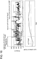
- FIG.18 is a table representing relationships among a temperature of a SCR catalyst, NOx concentration at an inlet and an outlet of the SCR and an operation time of the engine in the SCR unit for reducing nitrogen oxides (NOx).
- NOx concentration at the outlet of the SCR is relatively high until the catalyst temperature of the SCR unit reaches its activating temperature, and the SCR unit does not fully demonstrate the NOx purification function. Therefore it is necessary to raise the temperature of the exhaust gas purifier such as the SCR unit at an early stage during the warm-up operation such as immediately after starting the engine, in order to perform the exhaust gas purification at an early stage.
- Patent Literature 1 is an example of controlling the fuel injection timing.
- Patent Literature 2 is an example of controlling the flow rate of the air to be supplied to the engine.
- JP 2003-065121 A discloses a solution capable of promoting warming-up of catalyst while suppressing HC concentration in exhaust gas.
- an injection amount ratio of pilot injection is set to a higher value than an injection amount ratio of pilot injection performed in a normal operation condition after the warming-up period.
- injection time of main injection during the warming-up period is set to the time more delayed than injection amount time of main injection performed in a normal operation condition after the warming-up period.
- JP 3972611 B discloses a solution capable of preventing exhaust performance deterioration and combustion instability when reducing an excess air ratio for raising temperature of exhaust to provide fast activation of an exhaust emission control catalyst.
- the excessive air ratio is reduced by an intake throttle valve, a variable displacement type supercharger, and post injection of a fuel injection valve.
- an EGR ratio is controlled by an EGR valve in response to reduction of the excessive air ratio. If there is combustion instability right after starting or the like, the reduction of the excessive air ratio is prohibited.
- FR 2 846 999 A1 discloses an engine system comprising a diesel engine, an air inlet system, and an exhaust gas catalyzer, where the air intake is throttled as a function of the catalyzer temperature to increase the temperature of the exhaust gases reaching the catalyzer
- US 2004/000136 A1 discloses a method of controlling an internal combustion engine for warm-up of catalyst of an exhaust gas treatment device.
- the method comprises generating a warm-up demand for heating the catalyst subject to constraint on stable combustion. Based on the warm-up demand, a reduction in excess air ratio is determined.
- a desired value in excess air ratio is modified by the reduction to provide a modified desired value in excess air ratio.
- a desired value in EGR rate is modified to provide a modified desired value in EGR rate.
- an EGR command signal is determined.
- US 5 652 380 A discloses an apparatus and a method for detecting output fluctuations of an internal combustion engine, and an apparatus and method for controlling the engine.
- a standard deviation and mean value of a value for the cylinder pressure integrated over a predetermined interval are computed.
- a value for the standard deviation divided by the mean value is then made an index value for judging a limit of output fluctuations.
- the index value is less than a predetermined value corresponding to the output fluctuations, then weakening of the air-fuel ratio and retarding of the ignition timing is proceeded, while when the index value is equal to or greater than the predetermined value, it is judged that the limit of the output fluctuations has been exceeded, and the air-fuel ratio is corrected to the rich side, and the ignition timing is corrected to the advance side.
- the air flow control is comparatively most effective in raising the temperature.
- the pressure in the cylinder decreases. If the air flow control is performed at an early stage of the warm-up operation, combustion in the engine becomes unstable.
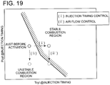
- FIG.19 is an illustration of a relationship between timing for starting the air flow control and an engine combustion state according to related art. It is determined whether the combustion state is stable or unstable based on a temperature inside the cylinder (T cyl ) and a pressure inside the cylinder (P cyl ) at the fuel injection timing. The higher the temperature and the pressure are inside the cylinder, the more stable the combustion state is. As illustrated in FIG.19 , when the air flow control (ii) is performed immediately in such a state that the engine is still in an unstable combustion state right after the engine starting, the combustion state becomes more unstable.
- the injection timing control (i) is performed prior to the air flow control (ii) so as to raise the temperature inside the cylinder, if the temperature is raised insufficiently in the cylinder, the air flow control (ii') causes the pressure in the cylinder to decrease, resulting in unstable combustion state.
- hydrocarbon (HC) emission increases. In the worst scenario, this causes fire extinction and then the engine stops.
- an exhaust gas purification system which is capable of raising the temperature of the exhaust gas purifier at an early stage while maintaining the engine in the stable combustion state during the warm-up operation such as immediately after the engine starting.
- an object of the present invention to provide an exhaust gas purification system for an internal combustion engine, which is capable of suppressing HC emission increase and raising the temperature of the exhaust gas purifier at an early stage while maintaining the stable combustion state during the warm-up operation such as immediately after the engine starting.
- the present invention was made to achieve the object of the present invention in view of the above issues and provides an exhaust gas purification system for an internal combustion engine provided with an engine, an exhaust passage where exhaust gas exhausted from the engine passes, and an exhaust gas purifier installed in the exhaust passage.
- the exhaust gas purification system comprises:
- the timing of activating the air flow control unit is controlled by the activation timing control unit so that the combustion state in the engine does not become unstable.
- the air flow control possibly makes the engine combustion unstable while being effective in raising the temperature.
- the exhaust gas purification system for the internal combustion engine is capable of suppressing HC emission increase and raising the temperature of the exhaust gas purifier at an early stage while maintaining the stable combustion state during the warm-up operation such as immediately after the engine starting.
- the activation timing control unit may be configured to activate the air flow control unit after prescribed time has passed since starting of the engine, the prescribed time being calculated based on a rotation speed of the engine and a fuel injection amount.
- the prescribed time may be corrected based on at least one of an ambient temperature or an ambient pressure in such a state that the engine operates.
- the temperature rise of the exhaust gas purifier just before the engine starting and suppression of the HC exhaust increase can be controlled by a simple method.
- the prescribed time to the activation of the air flow control unit is corrected according to the ambient temperature and/or the ambient pressure and thus the timing for activating the air flow control unit can be determined with precision in accordance with the ambient temperature and the ambient pressure.
- the activation timing control unit may be configured to activate the air flow control unit when a temperature of cooling water for cooling the engine or a temperature of lubricating oil flowing inside the engine becomes not less than a threshold value.
- the threshold value of the cooling water or the lubricating oil may be corrected based on at least one of an ambient temperature or an ambient pressure in such a state that the engine is activated.
- the timing for activating the air flow control unit can be controlled by knowing the combustion state in the engine from the temperature of the cooling water or the lubricating oil.
- the threshold value of the temperature of the cooling water or the lubricating oil is corrected according to the ambient temperature and/or the ambient pressure to precisely determine the timing for activating the air flow control unit in accordance with the ambient temperature and/or the ambient pressure.
- the activation timing control unit is configured to estimate a temperature and a pressure in a cylinder of the engine and control the timing of activating the air flow control unit based on the estimated temperature and pressure in the cylinder of the engine, the estimated pressure being estimated.
- the combustion state in the engine after the air flow control is performed is estimated with precision and then the timing for activating the air flow control unit is controlled.
- the timing for activating the air flow control unit is controlled.
- the activation timing control unit comprises a pressure detector for detecting a pressure in a cylinder of the engine, and the activation timing control unit is configured to control the timing of activating the air flow control unit based on the pressure in the cylinder detected by the pressure detector.
- a cylinder pressure in the cylinder is directly measured by the cylinder pressure measuring unit so as to obtain combustion stability of the engine directly and also to control the timing for activating the air flow control unit at the same time. Therefore, the air flow control can be performed while detecting the combustion state in the engine in real time. As a result, it is possible to secure stable combustion in the engine and also to achieve temperature rise of the exhaust gas purifier at an early stage.
- an exhaust gas purification system for an internal combustion engine which is capable of securing stable combustion in the engine, suppressing HC emission increase and raising a temperature of an exhaust gas purifier at an early stage during a warm-up operation such as immediately after engine starting.
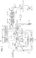
- FIG.1 is an overall structure of a diesel engine equipped with an exhaust gas purification system according to embodiments of the present invention. Referring to FIG.1 , the overall structure of the exhaust gas purification system for an internal combustion engine is described.
- the diesel engine equipped with the exhaust purification system is formed by: a variety of devices and pipings such as an engine 1, an exhaust passage 3, an air supply passage 13, a variable geometry turbocharger 11, a common fuel injection unit 18, and an EGR piping 23; a variety of exhaust gas purification devices such as a DOC unit 5, an oxidation catalyst (DOC unit) 5, a diesel particulate filter (DPF unit)7, and a selective reduction catalyst (SCR unit) 9; an engine controller (ECU) 19 for controlling these devices; and a variety of sensors.
- DOC unit 5 an oxidation catalyst
- DPF unit diesel particulate filter
- SCR unit selective reduction catalyst
- the exhaust passage 3 is connected to a downstream of the engine 1.
- the DOC unit 5 and the DPF unit 7 are provided in the exhaust passage 3.
- the DOC unit 5 is configured to oxidize HC (hydrocarbon) and CO (carbon monoxide) contained in the exhaust gas and also oxidize NO (nitric oxide) contained in the exhaust gas into NO 2 (nitrogen oxide).
- the DPF unit 7 is provided downstream of the DOC unit 5 to capture and remove particulate matter (PM) such as soot contained in the exhaust gas from the exhaust gas.
- PM particulate matter
- a urea aqueous injection unit 8 is provided downstream of the DPF unit 7 and immediately downstream of the urea aqueous injection unit 8, a SCR unit 9 is provided.
- the urea aqueous injection unit 8 injects urea aqueous to the exhaust passage 3 from an injection nozzle 8a in accordance with a control signal from the ECU 19.
- the urea aqueous is stored in a urea aqueous tank 8b.
- the urea aqueous injected to the exhaust passage 3 is hydrolyzed by heat of the exhaust gas 27 to ammonia (NH 3 ).
- the produced ammonia (NH 3 ) becomes reducing agent to perform reduction of NOx contained in the exhaust gas 27 in the SCR unit 9.
- the catalyst supported in the DOC unit 5 and the SCR unit 9 needs to be heated to or above the activating temperature.
- the DPF unit 7 needs to be heated to or above a prescribed temperature. More specifically, it is necessary to heat the exhaust gas purifiers to or above a prescribed temperature for the exhaust gas purifiers to fully function.
- an air flow control unit 50 is provided to raise the temperatures of the exhaust gas purifiers. The air flow control unit 50 is described later in details.
- the air supply passage 13 is connected to an upstream side of the engine 1.
- the variable geometry turbocharger 11 is provided between the air supply passage 11 and the exhaust passage 3.
- the variable geometry turbocharger 11 includes an exhaust gas turbine 11b arranged in the exhaust passage 3 and a compressor 11a arranged in the air supply passage 13.
- the compressor 11a is driven coaxially by the exhaust gas turbine 11b.
- the variable geometry turbocharger 11 is configured so that an opening degree of a variable nozzle vane (not shown), an opening degree of a wastegate valve (not shown) are adjusted based on a control signal from the ECU 19 to control a flow rate of air 26 exhausted from the compressor 11a.
- An intercooler 15 and an air supply throttle valve 17 are provided in the air supply passage 13.
- the air 26 exhausted from the compressor 11a is cooled in by the intercooler 15, passes through the air supply throttle valve 17 and then enters a combustion chamber 1a of each cylinder of the engine 1.
- the air supply throttle valve 17 is configured so that the opening is adjusted based on the control signal from the ECU 19 to control the flow rate of the air supplied to the engine 1.
- a common rail fuel injection device 18 is provided to inject fuel to the combustion chamber 1a.
- the common rail fuel injection device 18 is configured so that the injection timing and the injection amount are controller based on the control signal from the ECU 19.
- An injection timing control which is described later is performed by controlling the injection timing and the amount of fuel injected to the combustion chamber 1a from the common rail fuel injection timing 18 based on the control signal from the ECU 19 to vary the injection timing and injection amount from those of a normal operation mode.
- the EGR piping 23 branches from the exhaust passage 3 on the upstream side of the exhaust gas turbine 11b and is connected to a downstream side of the air supply throttle valve 17.
- an EGR cooler 24 and an EGR valve 25 are arranged in the EGR piping 23, an EGR cooler 24 and an EGR valve 25.
- the exhaust gas 27 exhausted from the engine 1 partially enters the EGR piping 23 to recirculate to the engine 1.
- the exhaust gas 27 exhausted from the engine 1 passes through the exhaust passage 3 to drive the exhaust turbine 11b, thereby coaxially driving the compressor 11a. Then the exhaust gas 27 passes through the exhaust passage 3 and then passes through the DOC unit 5, the DPF unit 7 and the SCR unit 9.
- an air flow meter 31 is arranged to detect the flow rate of the air entering the compressor 11a. A signal regarding the detected flow rate of air is inputted to the ECU 19.
- a DOC inlet temperature sensor 35 In the exhaust passage 3, a DOC inlet temperature sensor 35, a DPF inlet pressure sensor 36, a DPF inlet temperature sensor 37, a DPF pressure difference sensor 38 and a DPF outlet temperature sensor 39 are provided. Signals regarding a DOC inlet temperature sensor, a DPF inlet temperature, etc detected by these sensors are inputted to the ECU 19. On a downstream side of the SCR unit 9, a SCR outlet temperature sensor 33 and a NOx sensor 34 are arranged to detect a temperature at the downstream side of the SCR unit 9 and NOx concentration. Signals regarding the detected temperature and the detected NOx concentration are inputted to the ECU 19.
- an air supply temperature sensor 41 and an air supply pressure sensor 43 are arranged to detect an air supply temperature and an air supply pressure respectively. Signals regarding the detected air supply temperature and the detected air supply pressure are inputted to the ECU 19. An appropriate EGR amount is calculated based on these air supply temperature and air supply pressure so as to control the opening and closing of the EGR valve 25.
- an engine rotation speed and the fuel injection amount are calculated based on signals inputted from a variety of sensors such as a crank sensor, a cam sensor, an accelerator sensor and a throttle sensor that are not illustrated. Further, a cooling air passage (not shown) is formed around the engine 1 and a cooling water temperature sensor (not shown) is arranged to detect a temperature of the cooling air flowing in the cooling air passage.
- the ECU 19 is formed by a microcomputer having a central processing unit (CPU), a random access memory (RAM), a read-only memory (ROM), I/O interface, etc.
- the signals from the above sensors are inputted to the CPU via the I/O interface.
- the CPU is configured to perform a variety of controls in accordance with a control program stored in the ROM. As illustrated in FIG.1 , the air flow control unit 50 and an activation timing control unit 52 are formed by the ECU unit 19.
- FIG.2 is a block diagram illustrating the air flow control unit 50.
- the air flow control unit 50 is configured to control the opening of the air supply throttle valve 17 and the variable geometry turbocharger 11 based on a command from the activation timing control unit 52 so as to control (reduce) the flow rate of the air supplied to the engine 1. Further, the air flow control unit 50 is not necessary configured to control both the air supply throttle valve 17 and the variable geometry turbocharger 11.
- the air flow control unit 50b may be configured to control one of the air supply throttle valve 17 and the variable geometry turbocharger 11 so as to control (reduce) the flow rate of the air supplied to the engine 1.
- the air flow control has a high effect of raising the temperature and is extremely effective in raising the temperature of the exhaust gas purifier in an early stage during the warm-up operation such as immediately after the engine starting.
- the flow rate of the air is controlled too early after the engine starting, the combustion state in the engine becomes unstable as the pressure in the cylinder decreases once the flow rate of the air is controlled as described in FIG. 19 .
- the timing of activating the air flow control unit 50 is controlled by the activating timing control unit 52 so as to avoid the combustion state in the engine being unstable even if the air flow control is performed.
- Embodiments of the activation timing control unit 52 are described below in details.
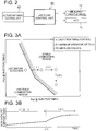
- FIG.3A is a conceptual drawing representing a relationship between a timing of activating an air flow control and an engine combustion state according to an example not belonging to the claimed invention.
- FIG.3B is a conceptual drawing representing a relationship between an operating time of the engine and a temperature of the SCR catalyst support.
- the activation timing control unit 52 is configured to perform the injection timing control (i) and the warm-up operation (ii) of the engine 1 after the engine starting as illustrated in FIG.3A and FIG.3B .
- the air flow control (iii) is performed after a prescribed time (t1) since the engine starting.
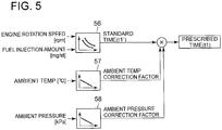
- the prescribed time (t1) is calculated as illustrated in FIG.5 by multiplying a standard time (t1') by a temperature correction factor and a pressure correction factor (temperature/pressure correction).
- the standard time is obtained from a standard map 56 by inputting the engine rotation speed (Ne) of the engine 1 and the fuel injection amount (Qf) to the standard map 56.
- the temperature correction factor is obtained from a temperature correction map 57 by inputting an ambient temperature to the temperature correction map 57.
- the pressure correction factor is obtained from a pressure correction map 58 by inputting an ambient pressure to the pressure correction map 58.
- the standard time (t1') is the prescribed time (t1) in FIG.5 .
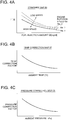
- the relationship between the engine rotation speed (Ne) and the standard time (t'1) represents in FIG.4A that the higher the engine rotation speed (Ne) is, the shorter the standard time (t'1) becomes, whereas the lower the engine rotation speed (Ne) is, the longer the standard time (t'1) becomes.
- the relationship between the fuel injection amount (Qf) and the standard time (t1') represents that the greater the fuel injection amount (Qf) is, the shorter the standard time (t'1) becomes, whereas the smaller the fuel injection amount (Qf) is, the longer the standard time (t'1) becomes.
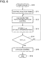
- the activation timing control unit 52 controls the injection timing (S11) to raise the temperature of the engine.
- the time for activating the air flow control (the prescribed time: t1) is calculated (S12).
- the calculated prescribed time (t1) is stored (S13) and the stored prescribed time (t1) is compared with an elapsed time (t) (S14).
- t ⁇ t1 YES in S14
- the air flow control is performed (S15).
- t ⁇ t1 NO in S14
- the process returns to the step S12 without performing the air flow control.
- the activation timing control unit 52 is configured to activate the air flow control unit 50 after the prescribed time (t1) has elapsed since the starting of the engine 1.
- the prescribed time (t1) is calculated, as illustrated in FIG.5 , from the standard map 56 by inputting the rotation speed (Ne) of the engine 1 and the fuel injection amount (Qf) into the standard map 56. Further, if desired, the prescribed time (t1) is corrected by the ambient temperature and the ambient pressure of the engine operation state.
- the temperature rise of the exhaust gas purifier just before the engine starting and suppression of the HC exhaust increase can be controlled by a simple method. Meanwhile, the prescribed time is corrected according to the ambient temperature and/or the ambient pressure and thus the timing for activating the air flow control unit 50 can be determined precisely in accordance with the ambient temperature and the ambient pressure.
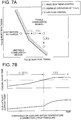
- FIG.7A is a conceptual drawing representing a relationship between the timing of activating the air flow control and the engine combustion state according to a different example not belonging to the claimed invention.
- FIG.7B is a conceptual drawing representing a relationship between the operating time of the engine and the temperature of the SCR catalyst support and the temperature of the cooling water.
- the activation timing control unit 52 is configured to perform, after the engine starting, the injection timing control (i) and the warm-up operation (ii) of the engine 1 as illustrated in FIG.7A and FIG.7B .
- the activation timing control unit 52 is configured to perform the air flow control (iii) once the temperature of the engine cooling water reaches a prescribed temperature (tw1) of the cooling water. Further, the temperature of the engine cooling water is obtainable by a cooling water temperature detector or the like (not illustrated).
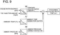
- the prescribed temperature (tw1) of the cooling water is calculated as illustrated in FIG.9 by multiplying a standard temperature of the cooling water (tw1') by a temperature correction factor and a pressure correction factor (temperature/pressure correction).
- the standard temperature of the cooling water (tw1') is obtained from a standard map 66 by inputting the engine rotation speed (Ne) of the engine 1 and the fuel injection amount (Qf) to the standard map 66.
- the temperature correction factor is obtained from a temperature correction map 67 by inputting an ambient temperature to the temperature correction map 67.
- the pressure correction factor is obtained from a pressure correction map 68 by inputting an ambient pressure to the pressure correction map 68.
- the standard temperature of the cooling water (tw1') is the prescribed temperature (tw1) in FIG.9 .
- the relationship between the engine rotation speed (Ne) and the standard temperature of the cooling water (tw'1) represents in FIG.8A that the higher the engine rotation speed (Ne) is, the lower the standard temperature of the cooling water (tw'1) becomes to a prescribed fuel injection amount, whereas the lower the engine rotation speed (Ne) is, the higher the standard temperature of the cooling water (tw'1) becomes.
- the relationship between the fuel injection amount (Qf) and the standard temperature of the cooling water (tw1') represents that the greater the fuel injection amount (Qf) is, the lower the standard temperature of the cooling water (tw'1) becomes, whereas the smaller the fuel injection amount (Qf) is, the higher the standard temperature of the cooling water (tw'1) becomes.
- the standard temperature (tw1') of the cooling water becomes approximately the same regardless of the engine rotation speed (Ne). Further as illustrated in FIG.8B , the higher the ambient temperature is, the smaller the temperature correction factor becomes, and as illustrated in FIG.8C , the higher the ambient pressure is, the smaller the pressure correction factor becomes.
- the activation timing control unit 52 controls the injection timing (S21) to raise the temperature of the engine.
- the prescribed temperature of the cooling water (tw1) for activating the air flow control is calculated (S22).
- the calculated prescribed temperature of the cooling water (tw1) is compared with a temperature (tw) of the cooling water detected by the cooling water temperature detector (not illustrated) (S23).
- tw ⁇ tw1 YES in S23
- the air flow control is performed (S24).
- tw ⁇ tw1 NO in S23
- the process returns to the step S22 without performing the air flow control.
- the activation timing control unit 52 is configured to activate the air flow control unit 50 in the case the temperature of the cooling water is at or above a threshold value (the prescribed temperature of the cooling water:tw1).
- the prescribed temperature of the cooling water (tw1) is calculated, as illustrated in FIG.9 , from the standard map 66 by inputting the rotation speed (Ne) of the engine 1 and the fuel injection amount (Qf) to the standard map 66. Further, if desired, the prescribed temperature of the cooling water (tw1) is corrected by the ambient temperature and the ambient pressure of the engine operation state. Further, the temperature of the engine cooling water is obtainable by the above cooling water temperature detector or the like.
- the combustion state in the engine 11 can be obtained using a temperature of lubricating oil passing through the interior of the engine instead of the temperature of the engine cooling water. More specifically, when the temperature of the lubricating oil passing through the interior of the engine 1 becomes at least the threshold value, the air flow control unit 50 may be configured to activate.
- the prescribed temperature of the lubricating oil (the threshold value) is calculated from the standard map by inputting the rotation speed (Ne) of the engine 1 and the fuel injection amount (Qf) to the standard map, in a manner similar to the case of using the engine cooling water.
- the prescribed temperature of the lubricating oil may be corrected by the ambient temperature and the ambient pressure of the engine operation state, similarly to the case of using the engine cooling water.
- the temperature of the lubricating oil is detectable by a temperature sensor (not illustrated) arranged at an appropriate position in a flow path of the lubricating oil.
- the timing for activating the air flow control unit 50 can be controlled by knowing the combustion state in the engine 1 using the temperature of the engine cooling water or the lubricating oil. Thus, it is possible to secure stable combustion in the engine 1 and also to achieve temperature rise of the exhaust gas purifiers at an early stage. In this case, the threshold value of the temperature of the engine cooling water or the lubricating oil is corrected according to the ambient temperature and/or the ambient pressure and thus the timing for activating the air flow control unit 50 can be determined precisely in accordance with the ambient temperature and the ambient pressure.
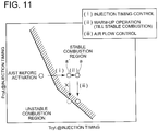
- FIG.11 is a conceptual drawing representing a relationship between the timing for activating the air flow control and the engine combustion state according to an embodiment of the claimed invention.
- the activation timing control unit 52 is configured to perform, after the engine starting, the injection timing control (i) and the warm-up operation (ii) of the engine 1.
- the activation timing control unit 52 is configured to perform the air flow control (iii) after confirming that the combustion state in the engine 1 is a "stable combustion" state.
- the “stable combustion” means that the combustion state in the engine 1 is stable even when the air flow control (iii) is performed. More specifically, at a point a' in FIG.11 , the combustion state in the engine 1 is not the stable combustion and at a point a, the combustion state in the engine is determined to become the stable combustion
- a stable combustion determination map 76 It is determined whether or not the combustion state in the engine 1 is the "stable combustion" using a stable combustion determination map 76 by inputting a cylinder temperature in the cylinder (T cyl ) and a cylinder pressure in the cylinder (P Cyl ) at the fuel injection timing ( ⁇ ) into the stable combustion determination map 76 as illustrated in FIG.12 .
- the cylinder temperature (T cyl ) at the fuel injection timing ( ⁇ ) is calculated (estimated) from the air supply temperature detected by the air supply temperature sensor 41 and the fuel injection timing ( ⁇ ).
- the cylinder pressure (P cyl ) at the fuel injection timing ( ⁇ ) is calculated (estimated) from the air supply pressure detected by the air supply pressure sensor 43 and the fuel injection timing ( ⁇ ).
- the fuel injection timing ( ⁇ ) is calculated from a map 78 by inputting the engine rotation speed (Ne) and the fuel injection amount (Qf) in the map 78.
- the activation timing control unit 52 controls the injection timing (S31) to raise the temperature of the engine.
- the cylinder temperature (T cyl ) at the fuel injection timing ( ⁇ ) and the cylinder pressure (P cyl ) at the fuel injection timing ( ⁇ ) are calculated (S32, S33).
- the steps S32 and S33 may be performed in reverse order or at the same time.
- the activation timing control unit 52 is configured to estimate the temperature and the pressure inside the cylinder of the engine and determine whether or not the inside of the cylinder after the air flow control is in the "stable combustion" state based on the estimated temperature and pressure inside the cylinder and then activate the air flow control unit 50.
- the combustion state in the engine 1 after the air flow control is performed is estimated with precision and then the timing for activating the air flow control unit 50 is controlled.
- the timing for activating the air flow control unit 50 is controlled.
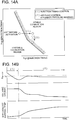
- FIG.14A is a table representing a relationship between the timing of activating the air flow control and the combustion state in the engine according to a different embodiment of the claimed invention.
- FIG.14B is a table representing a relationship between the engine operating time and each of a coefficient of variation of a maximum cylinder pressure (P max-COV ), a vane opening of a the variable geometry turbocharger and the temperature of the SCR catalyst support and illustrates the case where the air flow control is performed by adjusting the vane opening of the variable geometry turbocharger 11.
- P max-COV maximum cylinder pressure
- the activation timing control unit 52 includes a cylinder pressure measuring unit (not shown) for measuring the pressure in the cylinder.
- the activation timing control unit 52 is configured to perform, after the engine starting, the injection timing control (i) and then perform the air flow control (iii) while measuring the pressure in the cylinder by the cylinder pressure measuring unit and maintaining the engine 1 in the stable combustion state.
- the combustion state in the engine 1 is the "stable combustion” based on, for instance, a coefficient of variation (cov) of the maximum cylinder pressure (P max ). More specifically, the coefficient of variation of the maximum cylinder pressure (P max-COV ) is obtained from a standard deviation ⁇ of the maximum cylinder pressure (P max ) in a cycle of a specified time frame and an arithmetic mean value of the maximum cylinder pressure (P max-avg ) using a formula (1) below.
- a threshold value stored in the ROM of the ECU 19 in advance e.g. 1%
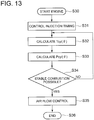
- the activation timing control unit 52 controls the injection timing (S41) to raise the temperature of the engine.
- the maximum cylinder pressure (P max ) is detected by the above-described cylinder pressure measuring unit (S42) and the coefficient of variation of the maximum cylinder pressure (P max-COV ) is calculated (S43). If the calculated coefficient of variation of the maximum cylinder pressure (P max-COV ) is not greater than the threshold value (YES in S44), the air flow control is performed (S45). In the air flow control, for instance, the vane opening of the variable geometry turbocharger 11 is gradually adjusted to slowly reduce the flow rate of the air supplied to the engine 1. On the other hand, if the calculated coefficient of variation of the maximum cylinder pressure (P max-COV ) is greater than the threshold value (NO in S44), the process returns to the step S42 without performing the air flow control.
- the coefficient of variation of the maximum cylinder pressure (P max-COV ) is calculated during the air flow control and is compared to the threshold value (S46). In the case where the coefficient of variation of the maximum cylinder pressure (P max-COV ) is below the threshold value (YES in S46), it is determined whether or not the air flow reaches a target control amount (S47). If the air flow has reached the target control amount, the air flow control stops there (S48). On the other hand, if the air flow hasn't reached the target control amount, the process returns to S45 to continue the air flow control. In contrast, in the case where the coefficient of variation of the maximum cylinder pressure (P max- cov) exceeds the threshold value (NO in S46), the air flow control is paused (S49) and the process returns to a step S42.
- the vane opening of the variable geometry turbocharger 11 is gradually adjusted to slowly reduce the flow rate of the air supplied to the engine 1.
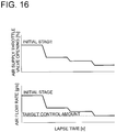
- this embodiment is not limited to this and, for instance, the opening of the air supply throttle valve 17 may be throttled in a phased manner to adjust the flow rate of the air supplied to the engine 1 in a phased manner as illustrated in FIG.16 .
- a control flow of this case is illustrated in FIG.17 . More specifically, to perform the air flow control in the phased manner, start of the air flow control (S45) and pause of the air flow control (S49) in FIG,15 are represented in FIG.17 as one step (S45') at which the air flow control is performed.
- the combustion state in the engine 1 is determined based on the coefficient of variation of the maximum cylinder pressure (P max-COV ).
- P max-COV maximum cylinder pressure
- this embodiment is not limited to this.
- an indicated mean effective pressure (IMEP) is obtained by the above-described cylinder pressure measuring unit and the combustion state in the engine 1 is determined based on coefficient of variation of the IMEP.
- the activation timing control unit 52 is provided with the cylinder pressure measuring unit (not shown) for measuring the cylinder pressure in the cylinder of the engine 1 and is configured to detect the combustion state in the engine 1 in real time based on the cylinder pressure measured by the cylinder pressure measuring unit and to control the timing for activating the air flow control unit 50.
- Combustion stability in the engine 1 is obtainable in real time directly using the cylinder pressure measuring unit and at the same time, the timing for activating the air flow control unit 50 can be controlled. Therefore, it is possible to secure stable combustion in the engine 1 and also to achieve temperature rise of the exhaust gas purifier at an early stage. While different embodiments of the invention have been described, it is obvious to those skilled in the art that various changes may be made without departing from the scope of the claimed invention.
- the SCR unit 9 is used as the exhaust gas purifier whose temperature is raised using the air flow control unit 50.
- the exhaust gas purifier of the embodiments is not limited to this and may include the DOC unit, DPF unit 7 or the like as well.
- the embodiments are applicable as an exhaust gas purification system for an internal combustion engine equipped with the DOC unit 5 and the DPF unit 7.
- the injection timing control is performed prior to the air flow control. However, this is not limitative and the injection timing control may not be performed.
- the exhaust gas purification system may be used as an exhaust gas purification system for a diesel engine equipped with exhaust gas purifiers such as DOC, DPF and SCR.
Landscapes
- Engineering & Computer Science (AREA)
- Chemical & Material Sciences (AREA)
- Combustion & Propulsion (AREA)
- Mechanical Engineering (AREA)
- General Engineering & Computer Science (AREA)
- Chemical Kinetics & Catalysis (AREA)
- Health & Medical Sciences (AREA)
- Toxicology (AREA)
- Materials Engineering (AREA)
- Combined Controls Of Internal Combustion Engines (AREA)
- Exhaust Gas After Treatment (AREA)
- Electrical Control Of Air Or Fuel Supplied To Internal-Combustion Engine (AREA)
- Control Of Throttle Valves Provided In The Intake System Or In The Exhaust System (AREA)
- Exhaust-Gas Circulating Devices (AREA)
Claims (2)
- Abgasreinigungssystem für einen Verbrennungsmotor mit einem Motor, einem Abgaskanal, durch den von dem Motor ausgestoßenes Abgas gelangt, und einem Abgasreiniger, der in dem Abgaskanal angeordnet ist, wobei das System umfasst:eine Luftstrom-Steuereinheit zum Reduzieren einer Strömungsgeschwindigkeit der dem Motor zuzuführenden Luft, um eine Temperatur des von dem Motor ausgestoßenen Abgases zu erhöhen; undeine Aktivierungstiming-Steuereinheit zum Steuern eines Timings des Aktivierens der Luftstrom-Steuereinheit;wobei die Aktivierungstiming-Steuereinheit zum Steuern des Timings des Aktivierens der Luftstrom-Steuereinheit konfiguriert ist, so dass ein Verbrennungszustand in dem Motor nicht instabil wird, wenn die Luftstrom-Steuereinheit aktiviert und die dem Motor zuzuführende Luft reduziert wird;wobei die Aktivierungstiming-Steuereinheit zum Schätzen einer Temperatur und eines Druckes in einem Zylinder des Motors und zum Steuern des Timings des Aktivierens der Luftstrom-Steuereinheit auf der Basis der geschätzten Temperatur und des Druckes in dem Zylinder des Motors konfiguriert ist; undwobei die Aktivierungstiming-Steuereinheit konfiguriert ist: zum Schätzen einer Temperatur und eines Druckes in einem Zylinder bei einem Kraftstoffeinspritz-Timing des Motors;zum Bestimmen, ob ein Innenraum des Zylinders nach der Luftstromsteuerung in einem stabilen Verbrennungszustand ist oder nicht, auf der Basis eines Plans zum Bestimmen einer stabilen Verbrennung, der die geschätzte Temperatur und Druck in dem Zylinder zum Kraftstoffeinspritz-Timing des Motors als Eingabedaten umfasst; undzum Aktivieren der Luftstrom-Steuereinheit wenn bestimmt wird, dass der Innenraum des Zylinders nach der Luftstromsteuerung in dem stabilen Verbrennungszustand ist.
- Abgasreinigungssystem für einen Verbrennungsmotor mit einem Motor, einem Abgaskanal, durch den von dem Motor ausgestoßenes Abgas gelangt, und einem Abgasreiniger, der in dem Abgaskanal angeordnet ist, wobei das System umfasst:eine Luftstrom-Steuereinheit zum Reduzieren einer Strömungsgeschwindigkeit der dem Motor zuzuführenden Luft, um eine Temperatur des von dem Motor ausgestoßenen Abgases zu erhöhen; undeine Aktivierungstiming-Steuereinheit zum Steuern eines Timings des Aktivierens der Luftstrom-Steuereinheit;wobei die Aktivierungstiming-Steuereinheit zum Steuern des Timings des Aktivierens der Luftstrom-Steuereinheit konfiguriert ist, so dass ein Verbrennungszustand in dem Motor nicht instabil wird, wenn die Luftstrom-Steuereinheit aktiviert und die dem Motor zuzuführende Luft reduziert wird;wobei die Aktivierungstiming-Steuereinheit einen Druckdetektor aufweist zum Detektieren eines Drucks in einem Zylinder des Motors; undwobei die Luftstrom-Steuereinheit zum allmählichen oder stufenweisen Reduzieren der Strömungsgeschwindigkeit der dem Motor zugeführten Luft konfiguriert ist, so dass ein Variationskoeffizient des von dem Druckdetektor detektierten Druckes in dem Zylinder einen im Voraus festgelegten Schwellenwert nicht überschreitet.
Applications Claiming Priority (2)
| Application Number | Priority Date | Filing Date | Title |
|---|---|---|---|
| JP2011251048A JP5986736B2 (ja) | 2011-11-16 | 2011-11-16 | 内燃機関の排気浄化システム |
| PCT/JP2012/078674 WO2013073409A1 (ja) | 2011-11-16 | 2012-11-06 | 内燃機関の排気浄化システム |
Publications (3)
| Publication Number | Publication Date |
|---|---|
| EP2781711A1 EP2781711A1 (de) | 2014-09-24 |
| EP2781711A4 EP2781711A4 (de) | 2016-03-23 |
| EP2781711B1 true EP2781711B1 (de) | 2017-09-20 |
Family
ID=48429473
Family Applications (1)
| Application Number | Title | Priority Date | Filing Date |
|---|---|---|---|
| EP12849177.6A Active EP2781711B1 (de) | 2011-11-16 | 2012-11-06 | Abgasreinigungssystem für einen verbrennungsmotor |
Country Status (6)
| Country | Link |
|---|---|
| US (1) | US9512785B2 (de) |
| EP (1) | EP2781711B1 (de) |
| JP (1) | JP5986736B2 (de) |
| CN (1) | CN103874833B (de) |
| IN (1) | IN2014DN03066A (de) |
| WO (1) | WO2013073409A1 (de) |
Families Citing this family (7)
| Publication number | Priority date | Publication date | Assignee | Title |
|---|---|---|---|---|
| US9890718B2 (en) * | 2012-01-11 | 2018-02-13 | Toyota Jidosha Kabushiki Kaisha | Control apparatus for internal combustion engine |
| DE102014211323B4 (de) * | 2013-07-17 | 2019-03-21 | Ford Global Technologies, Llc | Verfahren für den Betrieb einer Brennkraftmaschine, Brennkraftmaschine und Kraftfahrzeug mit verbesserter Zugleistung bei niedrigen Geschwindigkeiten |
| CN105486640B (zh) * | 2016-01-26 | 2018-04-24 | 大唐珲春发电厂 | 空气增压净化调整器 |
| JP6759630B2 (ja) | 2016-03-07 | 2020-09-23 | いすゞ自動車株式会社 | 排気浄化装置及び制御方法 |
| FR3057303B1 (fr) * | 2016-10-07 | 2019-10-11 | Renault S.A.S | Procede de maximisation d'un couple moteur |
| KR102085904B1 (ko) * | 2018-12-07 | 2020-03-06 | 현대오트론 주식회사 | 배기 가스 미립자 필터를 이용한 배기 가스 저감 시스템 및 방법 |
| CN113090398A (zh) * | 2020-01-09 | 2021-07-09 | 联合汽车电子有限公司 | 发动机控制方法 |
Family Cites Families (30)
| Publication number | Priority date | Publication date | Assignee | Title |
|---|---|---|---|---|
| US4466410A (en) * | 1981-07-15 | 1984-08-21 | Nippondenso Co., Ltd. | Air-fuel ratio control for internal combustion engine |
| JPS61123709A (ja) * | 1984-11-19 | 1986-06-11 | Nippon Soken Inc | 排気ガス微粒子浄化機能を有する内燃機関の制御装置 |
| JPH01211655A (ja) * | 1988-02-19 | 1989-08-24 | Mitsubishi Electric Corp | 内燃機関の制御装置 |
| JP3323974B2 (ja) | 1995-02-24 | 2002-09-09 | 株式会社ユニシアジェックス | 内燃機関の制御装置 |
| JP3292707B2 (ja) * | 1999-05-20 | 2002-06-17 | 三菱電機株式会社 | 内燃機関のバルブタイミング制御装置 |
| JP3680259B2 (ja) * | 2000-03-08 | 2005-08-10 | トヨタ自動車株式会社 | ディーゼル機関の燃料噴射装置 |
| JP4250856B2 (ja) | 2000-05-24 | 2009-04-08 | 三菱自動車工業株式会社 | 筒内噴射型内燃機関 |
| JP2002339764A (ja) | 2001-03-13 | 2002-11-27 | Komatsu Ltd | ディーゼルエンジン |
| JP2002349239A (ja) * | 2001-05-24 | 2002-12-04 | Isuzu Motors Ltd | ディーゼルエンジンの排気浄化装置 |
| JP3972611B2 (ja) | 2001-07-30 | 2007-09-05 | 日産自動車株式会社 | 内燃機関の排気浄化装置 |
| JP2003065121A (ja) | 2001-08-30 | 2003-03-05 | Toyota Motor Corp | ディーゼルエンジン |
| DE50110758D1 (de) * | 2001-09-25 | 2006-09-28 | Ford Global Tech Llc | Vorrichtung und Verfahren zur Regeneration einer Abgasbehandlungseinrichtung |
| JP3856118B2 (ja) * | 2002-01-31 | 2006-12-13 | 日産自動車株式会社 | 排気浄化装置 |
| JP4339572B2 (ja) * | 2002-08-21 | 2009-10-07 | 株式会社デンソー | 内燃機関の制御装置 |
| FR2846999B1 (fr) | 2002-11-12 | 2007-01-19 | Renault Sa | Systeme de motorisation comportant un moteur diesel et un catalyseur |
| JP2004176663A (ja) * | 2002-11-28 | 2004-06-24 | Honda Motor Co Ltd | 内燃機関の排気浄化装置 |
| JP4095979B2 (ja) | 2004-07-20 | 2008-06-04 | トヨタ自動車株式会社 | 内燃機関の排気浄化装置 |
| JP4385916B2 (ja) * | 2004-10-18 | 2009-12-16 | 日産自動車株式会社 | 筒内直接噴射式火花点火内燃機関の制御装置 |
| JP4574395B2 (ja) * | 2005-02-28 | 2010-11-04 | ヤンマー株式会社 | パティキュレートフィルタ再生機能を有する排ガス浄化装置及びその排ガス浄化装置を備えた内燃機関並びにパティキュレートフィルタ再生方法 |
| CN101091038B (zh) * | 2005-02-28 | 2011-09-14 | 洋马株式会社 | 排气气体净化装置和具有该排气气体净化装置的内燃机以及微粒过滤器再生方法 |
| JP4463144B2 (ja) | 2005-05-13 | 2010-05-12 | 本田技研工業株式会社 | 内燃機関の排ガス浄化装置 |
| JP2007113485A (ja) | 2005-10-20 | 2007-05-10 | Hitachi Ltd | 内燃機関の制御方法及び制御装置 |
| US7261086B2 (en) | 2005-10-21 | 2007-08-28 | Southwest Research Institute | Fast warm-up of diesel aftertreatment system during cold start |
| JP4197038B2 (ja) * | 2007-03-27 | 2008-12-17 | トヨタ自動車株式会社 | ハイブリッド自動車およびその制御方法 |
| JP5173340B2 (ja) * | 2007-09-26 | 2013-04-03 | 三菱重工業株式会社 | 排ガス浄化システム |
| JP2009214704A (ja) * | 2008-03-11 | 2009-09-24 | Nissan Motor Co Ltd | エンジンの始動制御装置 |
| JP2009281246A (ja) | 2008-05-21 | 2009-12-03 | Toyota Motor Corp | 内燃機関の制御装置 |
| JP5206475B2 (ja) | 2009-02-19 | 2013-06-12 | トヨタ自動車株式会社 | ハイブリッド車およびその制御方法 |
| US8381519B2 (en) * | 2009-11-03 | 2013-02-26 | International Engine Intellectual Property Company, Llc | Method of stationary regeneration of an engine exhaust particulate filter |
| JP5609795B2 (ja) * | 2011-07-12 | 2014-10-22 | 株式会社デンソー | 車両用過給装置 |
-
2011
- 2011-11-16 JP JP2011251048A patent/JP5986736B2/ja active Active
-
2012
- 2012-11-06 IN IN3066DEN2014 patent/IN2014DN03066A/en unknown
- 2012-11-06 EP EP12849177.6A patent/EP2781711B1/de active Active
- 2012-11-06 US US14/352,542 patent/US9512785B2/en active Active
- 2012-11-06 CN CN201280049773.8A patent/CN103874833B/zh active Active
- 2012-11-06 WO PCT/JP2012/078674 patent/WO2013073409A1/ja active Application Filing
Non-Patent Citations (1)
| Title |
|---|
| None * |
Also Published As
| Publication number | Publication date |
|---|---|
| EP2781711A1 (de) | 2014-09-24 |
| JP5986736B2 (ja) | 2016-09-06 |
| CN103874833B (zh) | 2016-08-17 |
| WO2013073409A1 (ja) | 2013-05-23 |
| JP2013104415A (ja) | 2013-05-30 |
| US20140251268A1 (en) | 2014-09-11 |
| CN103874833A (zh) | 2014-06-18 |
| US9512785B2 (en) | 2016-12-06 |
| IN2014DN03066A (de) | 2015-05-15 |
| EP2781711A4 (de) | 2016-03-23 |
Similar Documents
| Publication | Publication Date | Title |
|---|---|---|
| EP2781711B1 (de) | Abgasreinigungssystem für einen verbrennungsmotor | |
| US9133749B2 (en) | Ammonia storage set-point control for selective catalytic reduction applications | |
| JP4270155B2 (ja) | 排気浄化触媒の熱劣化状態検出装置 | |
| US20140123968A1 (en) | Method and apparatus for controlling the operation of a turbocharged internal combustion engine | |
| EP2940280B1 (de) | Verfahren und vorrichtung zur kalkulation der kraftstoff-cetan-zahl | |
| JP2014088800A (ja) | 内燃機関の排気浄化装置およびその排気浄化方法 | |
| JP4371045B2 (ja) | 内燃機関の排気浄化装置 | |
| US20140283502A1 (en) | Method of controlling an exhaust gas temperature of an internal combustion engine | |
| US8984860B2 (en) | Diesel engine and exhaust aftertreatment system and method of treating exhaust gases from a diesel engine | |
| EP2143919B1 (de) | Regenerationssystem für Partikelfilter | |
| JP5913619B2 (ja) | ディーゼルエンジン制御装置 | |
| EP2682579A2 (de) | Abgasemissionssteuerungssystem für einen Verbrennungsmotor und Steuerungsverfahren für Abgasemissionssteuerungssystem | |
| JP2008144711A (ja) | NOx触媒の異常診断装置及び異常診断方法 | |
| US8527185B2 (en) | Energy-based closed-loop control of turbine outlet temperature in a vehicle | |
| CN107407175B (zh) | 排气净化系统及催化剂再生方法 | |
| JP4775282B2 (ja) | 内燃機関の排気制御装置 | |
| JP2019073980A (ja) | 内燃機関の排気浄化装置 | |
| JP4345397B2 (ja) | エンジンの排気浄化装置 | |
| JP2016200111A (ja) | 排気浄化システム | |
| JP6589372B2 (ja) | 排気浄化装置 | |
| US8745967B2 (en) | System and method for controlling exhaust regeneration | |
| JP7106923B2 (ja) | エンジンの排気ガス状態推定方法及び触媒異常判定方法、並びに、エンジンの触媒異常判定装置 | |
| JP7106922B2 (ja) | エンジンの排気ガス状態推定方法及び触媒異常判定方法、並びに、エンジンの触媒異常判定装置 | |
| WO2017014772A1 (en) | System and method for controlling exhaust gas temperature | |
| JP2009250047A (ja) | 排気浄化装置の温度制御装置 |
Legal Events
| Date | Code | Title | Description |
|---|---|---|---|
| PUAI | Public reference made under article 153(3) epc to a published international application that has entered the european phase |
Free format text: ORIGINAL CODE: 0009012 |
|
| 17P | Request for examination filed |
Effective date: 20140417 |
|
| AK | Designated contracting states |
Kind code of ref document: A1 Designated state(s): AL AT BE BG CH CY CZ DE DK EE ES FI FR GB GR HR HU IE IS IT LI LT LU LV MC MK MT NL NO PL PT RO RS SE SI SK SM TR |
|
| DAX | Request for extension of the european patent (deleted) | ||
| RA4 | Supplementary search report drawn up and despatched (corrected) |
Effective date: 20160218 |
|
| RIC1 | Information provided on ipc code assigned before grant |
Ipc: F01N 3/023 20060101ALI20160212BHEP Ipc: F02D 41/04 20060101ALI20160212BHEP Ipc: F02D 35/02 20060101ALI20160212BHEP Ipc: F02D 41/00 20060101ALI20160212BHEP Ipc: F01N 3/20 20060101ALI20160212BHEP Ipc: F02D 41/22 20060101ALI20160212BHEP Ipc: F01N 3/24 20060101ALI20160212BHEP Ipc: F02D 45/00 20060101ALI20160212BHEP Ipc: F02D 41/02 20060101ALI20160212BHEP Ipc: F01N 3/18 20060101AFI20160212BHEP |
|
| GRAP | Despatch of communication of intention to grant a patent |
Free format text: ORIGINAL CODE: EPIDOSNIGR1 |
|
| INTG | Intention to grant announced |
Effective date: 20170405 |
|
| GRAS | Grant fee paid |
Free format text: ORIGINAL CODE: EPIDOSNIGR3 |
|
| GRAA | (expected) grant |
Free format text: ORIGINAL CODE: 0009210 |
|
| AK | Designated contracting states |
Kind code of ref document: B1 Designated state(s): AL AT BE BG CH CY CZ DE DK EE ES FI FR GB GR HR HU IE IS IT LI LT LU LV MC MK MT NL NO PL PT RO RS SE SI SK SM TR |
|
| REG | Reference to a national code |
Ref country code: GB Ref legal event code: FG4D |
|
| REG | Reference to a national code |
Ref country code: CH Ref legal event code: EP |
|
| REG | Reference to a national code |
Ref country code: AT Ref legal event code: REF Ref document number: 930321 Country of ref document: AT Kind code of ref document: T Effective date: 20171015 |
|
| REG | Reference to a national code |
Ref country code: IE Ref legal event code: FG4D |
|
| REG | Reference to a national code |
Ref country code: DE Ref legal event code: R096 Ref document number: 602012037656 Country of ref document: DE |
|
| REG | Reference to a national code |
Ref country code: NL Ref legal event code: MP Effective date: 20170920 |
|
| PG25 | Lapsed in a contracting state [announced via postgrant information from national office to epo] |
Ref country code: NO Free format text: LAPSE BECAUSE OF FAILURE TO SUBMIT A TRANSLATION OF THE DESCRIPTION OR TO PAY THE FEE WITHIN THE PRESCRIBED TIME-LIMIT Effective date: 20171220 Ref country code: SE Free format text: LAPSE BECAUSE OF FAILURE TO SUBMIT A TRANSLATION OF THE DESCRIPTION OR TO PAY THE FEE WITHIN THE PRESCRIBED TIME-LIMIT Effective date: 20170920 Ref country code: FI Free format text: LAPSE BECAUSE OF FAILURE TO SUBMIT A TRANSLATION OF THE DESCRIPTION OR TO PAY THE FEE WITHIN THE PRESCRIBED TIME-LIMIT Effective date: 20170920 Ref country code: LT Free format text: LAPSE BECAUSE OF FAILURE TO SUBMIT A TRANSLATION OF THE DESCRIPTION OR TO PAY THE FEE WITHIN THE PRESCRIBED TIME-LIMIT Effective date: 20170920 Ref country code: HR Free format text: LAPSE BECAUSE OF FAILURE TO SUBMIT A TRANSLATION OF THE DESCRIPTION OR TO PAY THE FEE WITHIN THE PRESCRIBED TIME-LIMIT Effective date: 20170920 |
|
| REG | Reference to a national code |
Ref country code: LT Ref legal event code: MG4D |
|
| REG | Reference to a national code |
Ref country code: AT Ref legal event code: MK05 Ref document number: 930321 Country of ref document: AT Kind code of ref document: T Effective date: 20170920 |
|
| PG25 | Lapsed in a contracting state [announced via postgrant information from national office to epo] |
Ref country code: RS Free format text: LAPSE BECAUSE OF FAILURE TO SUBMIT A TRANSLATION OF THE DESCRIPTION OR TO PAY THE FEE WITHIN THE PRESCRIBED TIME-LIMIT Effective date: 20170920 Ref country code: GR Free format text: LAPSE BECAUSE OF FAILURE TO SUBMIT A TRANSLATION OF THE DESCRIPTION OR TO PAY THE FEE WITHIN THE PRESCRIBED TIME-LIMIT Effective date: 20171221 Ref country code: LV Free format text: LAPSE BECAUSE OF FAILURE TO SUBMIT A TRANSLATION OF THE DESCRIPTION OR TO PAY THE FEE WITHIN THE PRESCRIBED TIME-LIMIT Effective date: 20170920 Ref country code: BG Free format text: LAPSE BECAUSE OF FAILURE TO SUBMIT A TRANSLATION OF THE DESCRIPTION OR TO PAY THE FEE WITHIN THE PRESCRIBED TIME-LIMIT Effective date: 20171220 |
|
| PG25 | Lapsed in a contracting state [announced via postgrant information from national office to epo] |
Ref country code: NL Free format text: LAPSE BECAUSE OF FAILURE TO SUBMIT A TRANSLATION OF THE DESCRIPTION OR TO PAY THE FEE WITHIN THE PRESCRIBED TIME-LIMIT Effective date: 20170920 |
|
| PG25 | Lapsed in a contracting state [announced via postgrant information from national office to epo] |
Ref country code: ES Free format text: LAPSE BECAUSE OF FAILURE TO SUBMIT A TRANSLATION OF THE DESCRIPTION OR TO PAY THE FEE WITHIN THE PRESCRIBED TIME-LIMIT Effective date: 20170920 Ref country code: PL Free format text: LAPSE BECAUSE OF FAILURE TO SUBMIT A TRANSLATION OF THE DESCRIPTION OR TO PAY THE FEE WITHIN THE PRESCRIBED TIME-LIMIT Effective date: 20170920 Ref country code: CZ Free format text: LAPSE BECAUSE OF FAILURE TO SUBMIT A TRANSLATION OF THE DESCRIPTION OR TO PAY THE FEE WITHIN THE PRESCRIBED TIME-LIMIT Effective date: 20170920 Ref country code: RO Free format text: LAPSE BECAUSE OF FAILURE TO SUBMIT A TRANSLATION OF THE DESCRIPTION OR TO PAY THE FEE WITHIN THE PRESCRIBED TIME-LIMIT Effective date: 20170920 |
|
| PG25 | Lapsed in a contracting state [announced via postgrant information from national office to epo] |
Ref country code: IS Free format text: LAPSE BECAUSE OF FAILURE TO SUBMIT A TRANSLATION OF THE DESCRIPTION OR TO PAY THE FEE WITHIN THE PRESCRIBED TIME-LIMIT Effective date: 20180120 Ref country code: SM Free format text: LAPSE BECAUSE OF FAILURE TO SUBMIT A TRANSLATION OF THE DESCRIPTION OR TO PAY THE FEE WITHIN THE PRESCRIBED TIME-LIMIT Effective date: 20170920 Ref country code: SK Free format text: LAPSE BECAUSE OF FAILURE TO SUBMIT A TRANSLATION OF THE DESCRIPTION OR TO PAY THE FEE WITHIN THE PRESCRIBED TIME-LIMIT Effective date: 20170920 Ref country code: EE Free format text: LAPSE BECAUSE OF FAILURE TO SUBMIT A TRANSLATION OF THE DESCRIPTION OR TO PAY THE FEE WITHIN THE PRESCRIBED TIME-LIMIT Effective date: 20170920 Ref country code: AT Free format text: LAPSE BECAUSE OF FAILURE TO SUBMIT A TRANSLATION OF THE DESCRIPTION OR TO PAY THE FEE WITHIN THE PRESCRIBED TIME-LIMIT Effective date: 20170920 |
|
| REG | Reference to a national code |
Ref country code: DE Ref legal event code: R097 Ref document number: 602012037656 Country of ref document: DE |
|
| PG25 | Lapsed in a contracting state [announced via postgrant information from national office to epo] |
Ref country code: MC Free format text: LAPSE BECAUSE OF FAILURE TO SUBMIT A TRANSLATION OF THE DESCRIPTION OR TO PAY THE FEE WITHIN THE PRESCRIBED TIME-LIMIT Effective date: 20170920 |
|
| PLBE | No opposition filed within time limit |
Free format text: ORIGINAL CODE: 0009261 |
|
| STAA | Information on the status of an ep patent application or granted ep patent |
Free format text: STATUS: NO OPPOSITION FILED WITHIN TIME LIMIT |
|
| PG25 | Lapsed in a contracting state [announced via postgrant information from national office to epo] |
Ref country code: DK Free format text: LAPSE BECAUSE OF FAILURE TO SUBMIT A TRANSLATION OF THE DESCRIPTION OR TO PAY THE FEE WITHIN THE PRESCRIBED TIME-LIMIT Effective date: 20170920 Ref country code: LI Free format text: LAPSE BECAUSE OF NON-PAYMENT OF DUE FEES Effective date: 20171130 Ref country code: CH Free format text: LAPSE BECAUSE OF NON-PAYMENT OF DUE FEES Effective date: 20171130 |
|
| 26N | No opposition filed |
Effective date: 20180621 |
|
| PG25 | Lapsed in a contracting state [announced via postgrant information from national office to epo] |
Ref country code: LU Free format text: LAPSE BECAUSE OF NON-PAYMENT OF DUE FEES Effective date: 20171106 |
|
| REG | Reference to a national code |
Ref country code: FR Ref legal event code: ST Effective date: 20180731 Ref country code: BE Ref legal event code: MM Effective date: 20171130 |
|
| REG | Reference to a national code |
Ref country code: IE Ref legal event code: MM4A |
|
| PG25 | Lapsed in a contracting state [announced via postgrant information from national office to epo] |
Ref country code: MT Free format text: LAPSE BECAUSE OF NON-PAYMENT OF DUE FEES Effective date: 20171106 |
|
| PG25 | Lapsed in a contracting state [announced via postgrant information from national office to epo] |
Ref country code: IE Free format text: LAPSE BECAUSE OF NON-PAYMENT OF DUE FEES Effective date: 20171106 Ref country code: FR Free format text: LAPSE BECAUSE OF NON-PAYMENT OF DUE FEES Effective date: 20171130 |
|
| PG25 | Lapsed in a contracting state [announced via postgrant information from national office to epo] |
Ref country code: BE Free format text: LAPSE BECAUSE OF NON-PAYMENT OF DUE FEES Effective date: 20171130 Ref country code: SI Free format text: LAPSE BECAUSE OF FAILURE TO SUBMIT A TRANSLATION OF THE DESCRIPTION OR TO PAY THE FEE WITHIN THE PRESCRIBED TIME-LIMIT Effective date: 20170920 |
|
| PG25 | Lapsed in a contracting state [announced via postgrant information from national office to epo] |
Ref country code: HU Free format text: LAPSE BECAUSE OF FAILURE TO SUBMIT A TRANSLATION OF THE DESCRIPTION OR TO PAY THE FEE WITHIN THE PRESCRIBED TIME-LIMIT; INVALID AB INITIO Effective date: 20121106 |
|
| PG25 | Lapsed in a contracting state [announced via postgrant information from national office to epo] |
Ref country code: CY Free format text: LAPSE BECAUSE OF NON-PAYMENT OF DUE FEES Effective date: 20170920 |
|
| PG25 | Lapsed in a contracting state [announced via postgrant information from national office to epo] |
Ref country code: MK Free format text: LAPSE BECAUSE OF FAILURE TO SUBMIT A TRANSLATION OF THE DESCRIPTION OR TO PAY THE FEE WITHIN THE PRESCRIBED TIME-LIMIT Effective date: 20170920 |
|
| REG | Reference to a national code |
Ref country code: GB Ref legal event code: 732E Free format text: REGISTERED BETWEEN 20200206 AND 20200212 |
|
| PG25 | Lapsed in a contracting state [announced via postgrant information from national office to epo] |
Ref country code: TR Free format text: LAPSE BECAUSE OF FAILURE TO SUBMIT A TRANSLATION OF THE DESCRIPTION OR TO PAY THE FEE WITHIN THE PRESCRIBED TIME-LIMIT Effective date: 20170920 |
|
| PG25 | Lapsed in a contracting state [announced via postgrant information from national office to epo] |
Ref country code: PT Free format text: LAPSE BECAUSE OF FAILURE TO SUBMIT A TRANSLATION OF THE DESCRIPTION OR TO PAY THE FEE WITHIN THE PRESCRIBED TIME-LIMIT Effective date: 20170920 |
|
| REG | Reference to a national code |
Ref country code: DE Ref legal event code: R081 Ref document number: 602012037656 Country of ref document: DE Owner name: MITSUBISHI HEAVY INDUSTRIES ENGINE & TURBOCHAR, JP Free format text: FORMER OWNER: MITSUBISHI HEAVY INDUSTRIES, LTD., TOKYO, JP Ref country code: DE Ref legal event code: R082 Ref document number: 602012037656 Country of ref document: DE |
|
| PG25 | Lapsed in a contracting state [announced via postgrant information from national office to epo] |
Ref country code: AL Free format text: LAPSE BECAUSE OF FAILURE TO SUBMIT A TRANSLATION OF THE DESCRIPTION OR TO PAY THE FEE WITHIN THE PRESCRIBED TIME-LIMIT Effective date: 20170920 |
|
| PGFP | Annual fee paid to national office [announced via postgrant information from national office to epo] |
Ref country code: GB Payment date: 20230928 Year of fee payment: 12 |
|
| PGFP | Annual fee paid to national office [announced via postgrant information from national office to epo] |
Ref country code: IT Payment date: 20231010 Year of fee payment: 12 Ref country code: DE Payment date: 20230929 Year of fee payment: 12 |