EP2781680A2 - Vormontierte Baueinheit einer Schließvorrichtung eines Gebäudes - Google Patents
Vormontierte Baueinheit einer Schließvorrichtung eines Gebäudes Download PDFInfo
- Publication number
- EP2781680A2 EP2781680A2 EP20140158567 EP14158567A EP2781680A2 EP 2781680 A2 EP2781680 A2 EP 2781680A2 EP 20140158567 EP20140158567 EP 20140158567 EP 14158567 A EP14158567 A EP 14158567A EP 2781680 A2 EP2781680 A2 EP 2781680A2
- Authority
- EP
- European Patent Office
- Prior art keywords
- frame
- building
- assembly according
- electrical energy
- drive device
- Prior art date
- Legal status (The legal status is an assumption and is not a legal conclusion. Google has not performed a legal analysis and makes no representation as to the accuracy of the status listed.)
- Granted
Links
Images
Classifications
-
- E—FIXED CONSTRUCTIONS
- E05—LOCKS; KEYS; WINDOW OR DOOR FITTINGS; SAFES
- E05F—DEVICES FOR MOVING WINGS INTO OPEN OR CLOSED POSITION; CHECKS FOR WINGS; WING FITTINGS NOT OTHERWISE PROVIDED FOR, CONCERNED WITH THE FUNCTIONING OF THE WING
- E05F15/00—Power-operated mechanisms for wings
- E05F15/70—Power-operated mechanisms for wings with automatic actuation
- E05F15/77—Power-operated mechanisms for wings with automatic actuation using wireless control
-
- E—FIXED CONSTRUCTIONS
- E05—LOCKS; KEYS; WINDOW OR DOOR FITTINGS; SAFES
- E05F—DEVICES FOR MOVING WINGS INTO OPEN OR CLOSED POSITION; CHECKS FOR WINGS; WING FITTINGS NOT OTHERWISE PROVIDED FOR, CONCERNED WITH THE FUNCTIONING OF THE WING
- E05F15/00—Power-operated mechanisms for wings
- E05F15/60—Power-operated mechanisms for wings using electrical actuators
- E05F15/603—Power-operated mechanisms for wings using electrical actuators using rotary electromotors
- E05F15/611—Power-operated mechanisms for wings using electrical actuators using rotary electromotors for swinging wings
-
- E—FIXED CONSTRUCTIONS
- E05—LOCKS; KEYS; WINDOW OR DOOR FITTINGS; SAFES
- E05Y—INDEXING SCHEME ASSOCIATED WITH SUBCLASSES E05D AND E05F, RELATING TO CONSTRUCTION ELEMENTS, ELECTRIC CONTROL, POWER SUPPLY, POWER SIGNAL OR TRANSMISSION, USER INTERFACES, MOUNTING OR COUPLING, DETAILS, ACCESSORIES, AUXILIARY OPERATIONS NOT OTHERWISE PROVIDED FOR, APPLICATION THEREOF
- E05Y2400/00—Electronic control; Electrical power; Power supply; Power or signal transmission; User interfaces
- E05Y2400/61—Power supply
- E05Y2400/612—Batteries
- E05Y2400/614—Batteries charging thereof
-
- E—FIXED CONSTRUCTIONS
- E05—LOCKS; KEYS; WINDOW OR DOOR FITTINGS; SAFES
- E05Y—INDEXING SCHEME ASSOCIATED WITH SUBCLASSES E05D AND E05F, RELATING TO CONSTRUCTION ELEMENTS, ELECTRIC CONTROL, POWER SUPPLY, POWER SIGNAL OR TRANSMISSION, USER INTERFACES, MOUNTING OR COUPLING, DETAILS, ACCESSORIES, AUXILIARY OPERATIONS NOT OTHERWISE PROVIDED FOR, APPLICATION THEREOF
- E05Y2400/00—Electronic control; Electrical power; Power supply; Power or signal transmission; User interfaces
- E05Y2400/61—Power supply
- E05Y2400/628—Solar cells
-
- E—FIXED CONSTRUCTIONS
- E05—LOCKS; KEYS; WINDOW OR DOOR FITTINGS; SAFES
- E05Y—INDEXING SCHEME ASSOCIATED WITH SUBCLASSES E05D AND E05F, RELATING TO CONSTRUCTION ELEMENTS, ELECTRIC CONTROL, POWER SUPPLY, POWER SIGNAL OR TRANSMISSION, USER INTERFACES, MOUNTING OR COUPLING, DETAILS, ACCESSORIES, AUXILIARY OPERATIONS NOT OTHERWISE PROVIDED FOR, APPLICATION THEREOF
- E05Y2900/00—Application of doors, windows, wings or fittings thereof
- E05Y2900/10—Application of doors, windows, wings or fittings thereof for buildings or parts thereof
- E05Y2900/13—Type of wing
- E05Y2900/148—Windows
Definitions
- the invention relates to a preassembled module of a locking device of a building according to the preamble of claim 1.
- Such an assembly comprises a frame and a control wing arranged on the frame for closing a building opening bounded by the frame.
- Such a closing device may be, for example, a window or a door of a building.
- the adjustment wing for example, is pivotally mounted on the frame and can be brought to release the building opening in an open position relative to the frame. In a closed position, the adjustable sash closes the building opening bounded by the frame.
- a window is conventionally to be mounted on a building
- a window manufacturer supplies a window module consisting of a frame and a window sash arranged thereon, which then enters a prepared opening in the masonry the building is used.
- a drive device for example for electrically adjusting the window sash or for actuating a locking device of the window sash, is provided on the window, then it must be connected to the electrical supply network of the building, for which purpose one or more separate lines must be routed to the window.
- the connection of the drive device must be made by an electrician, so that different trades are required for the installation of the window.
- additional structural units for example a window blind or the like, are to be used on the window, these must be mounted separately, which necessitates additional work steps, if necessary by other units.
- a mounting structure is provided, which can be attached to a building to carry a window or a door.
- the object of the present invention is to provide a preassembled subassembly of a closing device of a building, in particular a preassembled subassembly of a building window or a building door, which enables simple assembly on a building while minimizing the necessary assembly steps.
- the preassembled subassembly comprises at least one electrical energy generating device arranged on the frame above the adjusting vane, at least one electric energy store arranged on the frame or the adjusting vane and at least one driving device arranged on the frame or the adjusting vane, which with the energy generating device and / or the energy store for electrical supply is connected.
- the present invention is based on the idea to provide an assembly of a closure device which can be delivered in a pre-assembled state by a window manufacturer and installed in the preassembled state on a building.
- the preassembled module hereby provides a system that can be self-sufficient with regard to the electrical supply by the module both an energy generating device and an energy storage device, which serve to supply electrical power to one or more drive devices of the closing device.
- the fact that energy is generated by means of the energy generating device, such as a solar module for photovoltaic power generation, and stored by the energy storage, such as an accumulator, a supply of driving devices of the locking device by an external power supply is not necessarily required, but can alone through the power generation device and be provided the energy storage. This makes a connection of the locking device with a supply network of the building superfluous, so that this installation steps, which would otherwise be performed by an electrician, omitted and in particular no separate lines must be routed to the locking device.
- a significant advantage of the assembly according to the invention is that a pre-assembled module of a locking device is provided, which can be delivered in preassembled state and mounted in a simple manner on a prepared building opening.
- the electrical energy generating device may be formed for example by a solar module for photovoltaic power generation.
- other energy generating devices are also conceivable, for example a turbine or a wind turbine for generating energy from wind power or thermal energy generating devices that utilize existing thermal conditions for generating energy on a window or a door.
- the electrical energy store is advantageously formed by a rechargeable accumulator.
- the accumulator preferably has a charging capacity which ensures the operation of the closing device over a large period of time, for example several weeks or several months, for example three months, in order, for example, to be able to bridge the winter months in which the energy generation is reduced, for example, by a solar module ,
- the functional components can optionally be selected in the manner of a modular system depending on a desired configuration of the closing device so that depending on, for example, customer requirements, the pre-assembled module can be equipped and delivered in different ways.
- a roller blind box with a roller blind for at least partially covering the adjusting wing may be arranged on the frame.
- the roller blind can be driven by a drive device which is arranged, for example, on the frame and is supplied with electrical power via the energy generating device and the energy store of the module.
- the assembly may comprise further drive devices, which serve for adjusting the adjusting wing, for example for pivoting a door or a window sash.
- a drive device for example, act directly on a door or a window sash for adjusting. It is also conceivable, however, for a drive device to act on a locking device, comprising, for example, a window wing, provided with an adjustable locking pin, to actuate the locking device or to assist a manual actuation of the locking device in the manner of a servo motor.
- An actuating device for actuating the arranged on the frame, at least one drive device is preferably provided on the adjusting wing.
- the actuating device for example in the form of a handle, for example, communicates wirelessly with a drive device arranged on the frame and in this way controls the drive device, for example for adjusting a roller blind, for moving the adjusting leaf or for actuating a locking device.
- the actuating device may preferably have its own energy generating device, which is designed to generate electrical energy for operating the actuating device upon manual actuation of the actuating device.
- the actuator is thus designed as such as a self-sufficient module that is energetically independent of an external supply.
- the actuating device may comprise an actuating element to be actuated which acts, for example, on a piezo element for generating an electrical voltage on the piezoelement, so that a voltage can be tapped off via the piezoelement and used to supply, for example, a suitable communication circuit of the actuating device.
- an electronic control system for controlling the at least one drive device is arranged. Lines used to connect the
- Serving control electronics with the drive devices of the assembly are preferably laid in the frame and thus part of the preassembled module.
- the lines can be routed for example in profile parts of the frame, so that they are not visible from the outside.
- the assembly may also include one or more sensor packages disposed on the frame or the sash and providing sensors for sensing environmental conditions in the region of the closure.
- sensor components which can be configured, for example, as a brightness sensor, as a humidity sensor, as a wind sensor, as a temperature sensor, as air quality sensor, as a vibration sensor, as a glass breakage sensor, as a rain sensor, as an air flow sensor or as a noise sensor signals can be provided, the specific environmental condition such as the temperature or display a wind flow on a window or door and the control electronics can be supplied so that on the basis of the signals a suitable control, for example, a roller blind or an adjustment of a window or door leaf can be done.
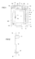
- Fig. 1 and 2 show in schematic views an embodiment of a closing device 1 in the form of a building window, in which on a frame 10, an adjusting wing 11 is arranged in the form of a pivotable window sash.
- the sash 11 closes in a closed position (shown in FIG Fig. 1 ) a building opening 2 of a building.
- the window wing 11 can be tilted about a first, horizontal pivot axis for opening or about a second, vertical pivot axis be pivoted so that the building opening 2 is at least partially released.
- assembly 1 represents a preassembled unit, which can be manufactured as such in the factory of a window manufacturer and delivered to a construction site.
- the assembly 1 can then in preassembled state as such at a prepared opening in a masonry M (see Fig. 2 ), in which case only the attachment of the assembly 1 to the masonry M is required, but further installation steps to complete the assembly 1 no longer need to be made so that the installation is simple and efficient on a construction site and in particular by a single Can be made (namely the window maker).
- the assembly 1 comprises different functional components arranged on the frame 10 or the sash 11 and may be used in a modular manner depending on a desired configuration or not.
- a modular system in which the module 1 can be equipped starting from a basic equipment in any way with additional functional components, the assembly takes place on the part of the window builder in the context of pre-assembly and thus does not complicate the installation on a construction site.
- Part of the basic equipment of the module is an electrical energy generating device 13, for example in the form of a photovoltaic solar module for generating electrical energy from light.
- the energy generating device 13 is connected to an energy store 14 in the form of a rechargeable battery, which is designed to temporarily store the energy generated by the energy generating device 13.
- the accumulator can in this case have a loading capacity, which is advantageously several months, so that, for example, low-season winter months can be bridged easily.
- the power generating device 13 and the energy storage 14 are used for electrical supply of several electrical functional modules of the assembly 1.
- a drive device 17 is provided for adjusting the window sash 11 or for actuating a locking device, which is used to lock the window sash 11 with the frame 10 is used, is formed.
- the electromotive drive device 17, for example in the form of a spindle drive, is connected via a line 140 to the energy store 14 and via a further line 160 connected to a control electronics 16.
- the control electronics 16 are used for electronic control of the operation of the drive device 17, for example, in response to a sensor signal of a sensor module 19, which is connected via a line 162 to the control electronics 16 and arranged on the frame.
- a roller blind box 12 with an attached thereto, along roller rails 120, 121 extendable roller blind 124 for covering the window sash 11 is arranged.
- a drive device 122 for driving the roller blind 124 is arranged in the roller blind box 12.
- the drive device 122 is connected via a line 161 to the control electronics 16 and via a line 141 to the energy storage 14 in connection.
- the power generating device 13 is arranged in the form of the solar module on top of the roller blind box 12 (see Fig. 2 ).
- the sensor module 19 can be configured, for example, as a temperature sensor, as a brightness sensor, as a humidity sensor, as a wind sensor, as an air quality sensor, as a vibration sensor, as a glass breakage sensor, as a rain sensor, as an airflow sensor or as a noise sensor.
- a temperature sensor as a brightness sensor
- a humidity sensor as a wind sensor
- an air quality sensor as a vibration sensor
- a glass breakage sensor as a rain sensor
- a noise sensor for example, an adjustment movement of the window sash 11 and / or an operation of the blinds 124 can be controlled.
- any number of sensor components for providing different sensor signals to the module 1, for example to the frame 10, may be provided.
- An actuating device 170 which serves to control the drive device 17 and possibly also the roller blind drive 122, is formed on the pivoting wing 11.
- the actuating device 170 for example in the form of a handle, can be configured to communicate wirelessly with the drive device 17 and / or the drive device 122 and, as such, can be designed as an energy-autonomous module.
- the actuating device 170 has its own energy generating device 171, which comprises, for example, an actuatable actuating element and a piezo block, which cooperate in such a way that upon actuation the actuating element acts on the piezo block, so that a voltage is tapped on the piezo block and used to supply electrical power to an electronic system the actuator 170 can be supplied.
- a further actuating device 123 may, for example, be provided on the frame 10 and serve for the dedicated operation of the roller blind drive 122.
- the actuating device 123 may, for example, be connected to the drive device 122 via a line, wherein, in principle, this actuating device 123 may also communicate wirelessly with the drive device 122 assigned to it.
- Part of the assembly 1 is also a sill 15, which is attached to a lower edge of the frame 10 and optionally also, as in Fig. 2 can carry an additional solar module 13 'for providing an additional power generating device (see Fig. 2 ).
- the module 1 provides an energy self-sufficient system that can basically do without external electrical supply. the supply of the electrical components of the assembly 1 via the power generating device 13 and the energy storage 14, which are integral components of the assembly 1, so that a wiring of the electrical functional components of the assembly 1 with an external power supply system is not required.
- a mains connection 18 can also be provided for connection to an external electrical supply network, which can provide an electrical (emergency) supply of the functional components of the module 1, in particular in the event of a failure of the energy generating device 13 or the energy store 12.
- the assembly can also realize a building door or other closing device for a building. It is also conceivable to equip the module with other functional components, which are pre-assembled with the other components in a modular manner.
Landscapes
- Engineering & Computer Science (AREA)
- Computer Networks & Wireless Communication (AREA)
- Power-Operated Mechanisms For Wings (AREA)
- Operating, Guiding And Securing Of Roll- Type Closing Members (AREA)
- Blinds (AREA)
Abstract
Description
- Die Erfindung betrifft eine vormontierte Baugruppe einer Schließvorrichtung eines Gebäudes nach dem Oberbegriff des Anspruchs 1.
- Eine derartige Baugruppe umfasst einen Rahmen und einen an dem Rahmen angeordneten Verstellflügel zum Verschließen einer durch den Rahmen begrenzten Gebäudeöffnung.
- Bei einer solchen Schließvorrichtung kann es sich beispielsweise um ein Fenster oder eine Tür eines Gebäudes handeln. Der Verstellflügel ist beispielsweise schwenkbar an dem Rahmen angeordnet und kann zum Freigeben der Gebäudeöffnung in eine geöffnete Stellung relativ zum Rahmen gebracht werden. In einer geschlossenen Stellung verschließt der Verstellflügel die durch den Rahmen begrenzte Gebäudeöffnung.
- Soll herkömmlich beispielsweise ein Fenster an einem Gebäude montiert werden, so liefert ein Fensterbauer ein Fenstermodul, bestehend aus einem Rahmen und einem daran angeordneten Fensterflügel, das dann in eine vorbereitete Öffnung im Mauerwerk des Gebäudes eingesetzt wird. Ist an dem Fenster eine Antriebsvorrichtung beispielsweise zum elektrischen Verstellen des Fensterflügels oder zum Betätigen einer Verriegelungseinrichtung des Fensterflügels vorgesehen, so muss diese an das elektrische Versorgungsnetz des Gebäudes angeschlossen werden, wozu eine oder mehrere separate Leitungen hin zum Fenster verlegt werden müssen. Dies ist insofern umständlich und nachteilig, als dass die Montage des Fensters an der vorbereiteten Gebäudeöffnung durch den Fensterbauer erfolgt, der Anschluss der Antriebsvorrichtung hingegen durch einen Elektriker vorgenommen werden muss, so dass unterschiedliche Gewerke für den Einbau des Fensters erforderlich sind. Sollen zusätzliche Baueinheiten, beispielsweise ein Fensterrollo oder dergleichen, am Fenster Verwendung finden, so sind diese separat zu montieren, was zusätzliche Arbeitsschritte, gegebenenfalls durch andere Gewerke, erforderlich macht.
- Bei einer aus der
EP 1 698 754 A1 bekannten Anordnung für ein Gebäude ist eine Befestigungsstruktur vorgesehen, die an einem Gebäude befestigt werden kann, um ein Fenster oder eine Tür zu tragen. - Aufgabe der vorliegenden Erfindung ist es, eine vormontierte Baugruppe einer Schließvorrichtung eines Gebäudes, insbesondere eine vormontierte Baugruppe eines Gebäudefensters oder einer Gebäudetür, bereitzustellen, die eine einfache Montage an einem Gebäude unter Minimierung der erforderlichen Montageschritte ermöglicht.
- Diese Aufgabe wird durch einen Gegenstand mit den Merkmalen des Anspruchs 1 gelöst.
- Demnach umfasst die vormontierte Baugruppe mindestens eine an dem Rahmen über dem Verstellflügel angeordnete elektrische Energieerzeugungseinrichtung, mindestens einen an dem Rahmen oder dem Verstellflügel angeordneten elektrischen Energiespeicher und mindestens eine an dem Rahmen oder dem Verstellflügel angeordnete Antriebsvorrichtung, die mit der Energieerzeugungseinrichtung und/oder dem Energiespeicher zur elektrischen Versorgung verbunden ist.
- Die vorliegende Erfindung geht von dem Gedanken aus, eine Baugruppe einer Schließvorrichtung bereitzustellen, die in einem vormontierten Zustand durch einen Fensterbauer ausgeliefert und in dem vormontierten Zustand an einem Gebäude installiert werden kann. Die vormontierte Baugruppe stellt hierbei ein System bereit, das mit Blick auf die elektrische Versorgung autark sein kann, indem die Baugruppe sowohl eine Energieerzeugungseinrichtung als auch einen Energiespeicher umfasst, die zu elektrischen Versorgung einer oder mehrerer Antriebsvorrichtungen der Schließvorrichtung dienen. Dadurch, dass mittels der Energieerzeugungseinrichtung, beispielsweise einem Solarmodul zur photovoltaischen Energieerzeugung, Energie erzeugt und mittels des Energiespeichers, beispielsweise einem Akkumulator, gespeichert wird, ist eine Versorgung der Antriebsvorrichtungen der Schließvorrichtung durch eine externe Stromversorgung nicht notwendigerweise erforderlich, sondern kann allein über die Energieerzeugungseinrichtung und den Energiespeicher bereitgestellt werden. Dies macht eine Verbindung der Schließvorrichtung mit einem Versorgungsnetzwerk des Gebäudes überflüssig, so dass dies betreffende Installationsschritte, die ansonsten durch einen Elektriker durchzuführen wären, entfallen und insbesondere auch keine gesonderten Leitungen hin zu der Schließvorrichtung verlegt werden müssen.
- Ein wesentlicher Vorteil der erfindungsgemäßen Baugruppe besteht darin, dass ein vormontiertes Modul einer Schließvorrichtung bereitgestellt wird, das in vormontiertem Zustand ausgeliefert und in einfacher Weise an einer vorbereiteten Gebäudeöffnung montiert werden kann.
- Die elektrische Energieerzeugungseinrichtung kann beispielsweise durch ein Solarmodul zur photovoltaischen Energieerzeugung ausgebildet sein. Denkbar sind aber auch andere Energieerzeugungseinrichtungen, beispielsweise eine Turbine oder ein Windrad zur Energieerzeugung aus Windkraft oder thermische Energieerzeugungseinrichtungen, die an einem Fenster oder einer Tür bestehende thermische Bedingungen zur Energieerzeugung ausnutzen.
- Der elektrische Energiespeicher ist vorteilhafterweise durch einen aufladbaren Akkumulator gebildet. Der Akkumulator weist vorzugsweise eine Ladekapazität auf, die den Betrieb der Schließvorrichtung über einen großen Zeitraum, beispielsweise mehrere Wochen oder mehrere Monate, zum Beispiel drei Monate, gewährleistet, um beispielsweise die Wintermonate überbrücken zu können, in denen die Energieerzeugung beispielsweise durch ein Solarmodul reduziert ist.
- Zusätzlich können an der Baugruppe weitere Funktionskomponenten angebracht sein. Die Funktionskomponenten können hierbei nach Art eines Baukastensystems wahlweise abhängig von einer gewünschten Konfiguration der Schließvorrichtung ausgewählt werden, so dass abhängig von beispielsweise Kundenwünschen die vormontierte Baugruppe in unterschiedlicher Weise bestückt und ausgeliefert werden kann.
- Beispielsweise kann an dem Rahmen ein Rollokasten mit einem Rollo zum zumindest teilweisen Abdecken des Verstellflügels angeordnet sein. Das Rollo kann über eine Antriebsvorrichtung angetrieben werden, die beispielsweise an dem Rahmen angeordnet ist und über die Energieerzeugungseinrichtung und den Energiespeicher der Baugruppe elektrisch versorgt wird.
- Die Baugruppe kann weitere Antriebsvorrichtungen aufweisen, die zum Verstellen des Verstellflügels, beispielsweise zum Verschwenken einer Tür oder eines Fensterflügels, dienen. Eine Antriebsvorrichtung kann beispielsweise direkt auf einen Türflügel oder einen Fensterflügel zum Verstellen einwirken. Denkbar ist aber auch, dass eine Antriebsvorrichtung auf eine Verriegelungseinrichtung, umfassend beispielsweise an einem Fensterflügel bekannterweise vorgesehene, verstellbare Verriegelungszapfen, einwirkt, um die Verriegelungseinrichtung zu betätigen oder eine manuelle Betätigung der Verriegelungseinrichtung nach Art eines Servomotors motorisch zu unterstützen.
- An dem Verstellflügel ist vorzugsweise eine Betätigungsseinrichtung zum Betätigen der an dem Rahmen angeordneten, mindestens einen Antriebsvorrichtung vorgesehen. Die Betätigungseinrichtung, beispielsweise in Form eines Griffs, kommuniziert beispielsweise drahtlos mit einer an dem Rahmen angeordneten Antriebsvorrichtung und steuert auf diese Weise die Antriebsvorrichtung beispielsweise zum Verstellen eines Rollos, zum Bewegen des Verstellflügels oder zum Betätigen einer Verriegelungseinrichtung. Die Betätigungseinrichtung kann vorzugsweise eine eigene Energieerzeugungseinrichtung aufweisen, die ausgebildet ist, bei manueller Betätigung der Betätigungseinrichtung elektrische Energie zum Betreiben der Betätigungseinrichtung zu erzeugen. Die Betätigungseinrichtung ist somit als solche als autarkes Modul ausgestaltet, die energetisch unabhängig ist von einer externen Versorgung. Beispielsweise kann die Betätigungseinrichtung ein zu betätigendes Betätigungselement umfassen, das bei Betätigung beispielsweise auf ein Piezoelement zur Erzeugung einer elektrischen Spannung an dem Piezoelement einwirkt, so dass über das Piezoelement eine Spannung abgegriffen und zur Versorgung beispielsweise eines geeigneten Kommunikationsschaltkreises der Betätigungseinrichtung verwendet werden kann.
- An dem Rahmen ist vorzugsweise auch eine Steuerelektronik zum Steuern der mindestens einen Antriebsvorrichtung angeordnet. Leitungen, die zur Verbindung der
- Steuerelektronik mit den Antriebsvorrichtungen der Baugruppe dienen, sind vorzugsweise in dem Rahmen verlegt und somit Bestandteil der vormontierten Baugruppe. Die Leitungen können beispielsweise in Profilteilen des Rahmens verlegt sein, so dass sie von außen nicht sichtbar sind.
- Die Baugruppe kann zudem einen oder mehrere Sensorbausteine aufweisen, die an dem Rahmen oder dem Verstellflügel angeordnet sind und eine Sensorik zur Erfassung von Umgebungsbedingungen im Bereich der Schließvorrichtung bereitstellen. Mittels solcher Sensorbausteine, die beispielsweise als Helligkeitssensor, als Luftfeuchtesensor, als Windsensor, als Temperatursensor, als Luftgütesensor, als Vibrationssensor, als Glasbruchsensor, als Regensensor, als Luftmengensensor oder als Lärmsensor ausgestaltet sein können, können Signale bereitgestellt werden, die bestimmte Umgebungsbedingung wie die Temperatur oder einen Windstrom an einem Fenster oder einer Tür anzeigen und der Steuerelektronik zugeführt werden können, damit anhand der Signale eine geeignete Steuerung beispielsweise eines Rollos oder einer Verstellbewegung eines Fenster- oder Türflügels erfolgen kann.
- Dadurch, dass die Sensorbausteine Bestandteil der vormontierten Baugruppe sind und somit an dem Rahmen oder dem Verstellflügel bereits vormontiert sind, ist eine nachträgliche Installation nicht erforderlich, so dass das Vorsehen solcher Sensorbausteine den Installationsaufwand nicht erhöht.
- Der der Erfindung zugrunde liegende Gedanke soll nachfolgend anhand des in den Figuren dargestellten Ausführungsbeispiels näher erläutert werden. Es zeigen:
- Fig. 1
- eine schematische Ansicht einer Schließvorrichtung in Form eines Fensters eines Gebäudes; und
- Fig. 2
- eine schematische Seitenansicht der Schließvorrichtung.
-
Fig. 1 und 2 zeigen in schematischen Ansichten ein Ausführungsbeispiel einer Schließvorrichtung 1 in Form eines Gebäudefensters, bei dem an einem Rahmen 10 ein Verstellflügel 11 in Form eines verschwenkbaren Fensterflügels angeordnet ist. Der Fensterflügel 11 verschließt in einer geschlossenen Stellung (dargestellt inFig. 1 ) eine Gebäudeöffnung 2 eines Gebäudes. Der Fensterflügel 11 kann zum Öffnen um eine erste, horizontale Schwenkachse verkippt oder um eine zweite, vertikale Schwenkachse verschwenkt werden, so dass die Gebäudeöffnung 2 zumindest teilweise freigegeben wird. - Die in
Fig. 1 dargestellte Baugruppe 1 stellt eine vormontierte Einheit dar, die als solche im Werk eines Fensterbauers hergestellt und an eine Baustelle ausgeliefert werden kann. Die Baugruppe 1 kann dann in vormontiertem Zustand als solche an einer vorbereiteten Öffnung in einem Mauerwerk M (sieheFig. 2 ) installiert werden, wobei hierzu lediglich die Anbringung der Baugruppe 1 an dem Mauerwerk M erforderlich ist, weitere Installationsschritte zur Komplettierung der Baugruppe 1 jedoch nicht mehr vorgenommen werden müssen, so dass sich die Installation auf einer Baustelle einfach und effizient gestaltet und insbesondere durch ein einziges Gewerk (nämlich den Fensterbauer) vorgenommen werden kann. - Die Baugruppe 1 umfasst unterschiedliche Funktionskomponenten, die an dem Rahmen 10 oder dem Fensterflügel 11 angeordnet sind und in modularer Weise abhängig von einer gewünschten Konfiguration verwendet werden können oder nicht. Auf diese Weise wird ein Baukastensystem bereitgestellt, bei dem die Baugruppe 1 ausgehend von einer Grundausstattung in beliebiger Weise mit zusätzlichen Funktionskomponenten bestückt werden kann, wobei die Bestückung aufseiten des Fensterbauers im Rahmen der Vormontage erfolgt und somit die Installation auf einer Baustelle nicht verkompliziert.
- Bestandteil der Grundausstattung der Baugruppe ist eine elektrische Energieerzeugungseinrichtung 13 beispielsweise in Form eines photovoltaischen Solarmoduls zur Erzeugung elektrischer Energie aus Licht. Die Energieerzeugungseinrichtung 13 steht in Verbindung mit einem Energiespeicher 14 in Form eines Akkumulators, der ausgelegt ist, die durch die Energieerzeugungseinrichtung 13 erzeugte Energie zwischenzuspeichern. Der Akkumulator kann hierbei eine Ladekapazität aufweisen, die vorteilhafterweise mehrere Monate beträgt, so dass beispielsweise lichtarme Wintermonate ohne Weiteres überbrückt werden können.
- Die Energieerzeugungseinrichtung 13 und der Energiespeicher 14 dienen zur elektrischen Versorgung mehrerer elektrischer Funktionsmodule der Baugruppe 1. So ist an dem Rahmen 10 eine Antriebsvorrichtung 17 vorgesehen, die zum Verstellen des Fensterflügels 11 oder zum Betätigen einer Verriegelungseinrichtung, die zur Verriegelung des Fensterflügels 11 mit dem Rahmen 10 dient, ausgebildet ist. Die elektromotorische Antriebsvorrichtung 17, beispielsweise in Form eines Spindelantriebs, ist über eine Leitung 140 mit dem Energiespeicher 14 und über eine weitere Leitung 160 mit einer Steuerelektronik 16 verbunden. Die Steuerelektronik 16 dient zur elektronischen Steuerung des Betriebs der Antriebsvorrichtung 17, beispielsweise in Abhängigkeit von einem Sensorsignal eines Sensorbausteins 19, der über eine Leitung 162 mit der Steuerelektronik 16 verbunden und an dem Rahmen angeordnet ist.
- An dem Rahmen 10 ist weiterhin ein Rollokasten 12 mit einem daran befindlichen, entlang von Rolloschienen 120, 121 ausfahrbaren Rollo 124 zum Abdecken des Fensterflügels 11 angeordnet. In dem Rollokasten 12 ist eine Antriebsvorrichtung 122 zum Antreiben des Rollos 124 angeordnet. Die Antriebsvorrichtung 122 steht über eine Leitung 161 mit der Steuerelektronik 16 und über eine Leitung 141 mit dem Energiespeicher 14 in Verbindung.
- Bei dem dargestellten Ausführungsbeispiel ist die Energieerzeugungseinrichtung 13 in Form des Solarmoduls oben auf dem Rollokasten 12 angeordnet (siehe
Fig. 2 ). - Der Sensorbaustein 19 kann beispielsweise als Temperatursensor, als Helligkeitssensor, als Luftfeuchtesensor, als Windsensor, als Luftgütesensor, als Vibrationssensor, als Glasbruchsensor, als Regensensor, als Luftmengensensor oder als Lärmsensor ausgestaltet sein. In Abhängigkeit der vom Sensorbaustein 19 erzeugten Signale kann beispielsweise eine Verstellbewegung des Fensterflügels 11 und/oder eine Betätigung des Rollos 124 gesteuert werden.
- Grundsätzlich können beliebig viele Sensorbausteine zur Bereitstellung unterschiedlicher Sensorsignale an der Baugruppe 1, beispielsweise an dem Rahmen 10 vorgesehen sein.
- An dem Schwenkflügel 11 ist eine Betätigungseinrichtung 170 ausgebildet, die zur Steuerung der Antriebsvorrichtung 17 und gegebenenfalls auch des Rolloantriebs 122 dient. Die Betätigungseinrichtung 170, beispielsweise in Form eines Griffs, kann ausgestaltet sein, drahtlos mit der Antriebsvorrichtung 17 und/oder der Antriebsvorrichtung 122 zu kommunizieren und kann als solche als energetisch autarkes Modul ausgebildet sein. Dazu weist die Betätigungseinrichtung 170 eine eigene Energieerzeugungseinrichtung 171 auf, die beispielsweise ein betätigbares Betätigungselement sowie einen Piezobaustein umfasst, die derart zusammenwirken, dass bei einer Betätigung das Betätigungselement auf den Piezobaustein einwirkt, so dass eine Spannung an dem Piezobaustein abgegriffen und zur elektrischen Versorgung einer Elektronik der Betätigungseinrichtung 170 zugeführt werden kann.
- Eine weitere Betätigungseinrichtung 123 kann beispielsweise an dem Rahmen 10 vorgesehen sein und zur dedizierten Bedienung des Rolloantriebs 122 dienen. Die Betätigungseinrichtung 123 kann beispielsweise über eine Leitung mit der Antriebsvorrichtung 122 verbunden sein, wobei grundsätzlich auch diese Betätigungseinrichtung 123 drahtlos mit der ihr zugeordneten Antriebsvorrichtung 122 kommunizieren kann.
- Bestandteil der Baugruppe 1 ist weiterhin eine Fensterbank 15, die an eine untere Kante des Rahmens 10 angesetzt ist und gegebenenfalls auch, wie in
Fig. 2 dargestellt, ein zusätzliches Solarmodul 13' zur Bereitstellung einer zusätzlichen Energieerzeugungseinrichtung tragen kann (sieheFig. 2 ). - Die Baugruppe 1 stellt ein energetisch autarkes System bereit, das grundsätzlich ohne externe elektrische Versorgung auskommen kann. die Versorgung der elektrischen Komponenten der Baugruppe 1 erfolgt über die Energieerzeugungseinrichtung 13 und den Energiespeicher 14, die integrale Bestandteile der Baugruppe 1 sind, so dass eine Verkabelung der elektrischen Funktionskomponenten der Baugruppe 1 mit einem externen Energieversorgungssystem nicht erforderlich ist.
- Grundsätzlich kann aber auch ein Netzanschluss 18 zur Verbindung mit einem externen elektrischen Versorgungsnetzwerk vorgesehen sein, der insbesondere im Fall eines Ausfalls der Energieerzeugungseinrichtung 13 oder des Energiespeichers 12 eine elektrische (Not-)Versorgung der Funktionskomponenten der Baugruppe 1 bereitstellen kann.
- Der der Erfindung zugrunde liegende Gedanke ist nicht auf die vorangehend geschilderten Ausführungsbeispiele beschränkt, sondern lässt sich grundsätzlich auch bei gänzlich anders gearteten Ausführungsformen verwirklichen. Insbesondere kann die Baugruppe auch eine Gebäudetür oder eine andere Schließvorrichtung für ein Gebäude verwirklichen. Denkbar ist zudem, die Baugruppe mit weiteren Funktionskomponenten zu bestücken, die mit den übrigen Komponenten in modularer Weise vormontiert werden.
-
- 1
- Baugruppe
- 10
- Rahmen
- 11
- Verstellflügel
- 12
- Rollokasten
- 120, 121
- Rolloschiene
- 122
- Rolloantrieb
- 123
- Betätigungseinrichtung
- 124
- Rollo
- 13, 13'
- Solarmodul
- 14
- Energiespeicher
- 140-142
- Leitung
- 15
- Fensterbank
- 16
- Steuerelektronik
- 160-162
- Leitung
- 17
- Antriebsvorrichtung
- 170
- Betätigungseinrichtung
- 171
- Energieerzeugungseinrichtung
- 18
- Netzanschluss
- 19
- Sensorbaustein
- 2
- Gebäudeöffnung
- M
- Mauerwerk
Claims (11)
- Vormontierte Baugruppe einer Schließvorrichtung eines Gebäudes, mit- einem Rahmen und- einem an dem Rahmen angeordneten Verstellflügel zum Verschließen einer durch den Rahmen begrenzten Gebäudeöffnung,gekennzeichnet durch- mindestens eine an dem Rahmen (10) oder dem Verstellflügel (11) angeordnete elektrische Energieerzeugungseinrichtung (13),- mindestens einen an dem Rahmen (10) oder dem Verstellflügel (11) angeordneten elektrischen Energiespeicher (14) und- mindestens eine an dem Rahmen (10) oder dem Verstellflügel (11) angeordnete Antriebsvorrichtung (17, 122), die mit der Energieerzeugungseinrichtung (13) und/oder dem Energiespeicher (14) zur elektrischen Versorgung verbunden ist.
- Baugruppe nach Anspruch 1, dadurch gekennzeichnet, dass die mindestens eine Antriebsvorrichtung (17, 122) im Betrieb der Baugruppe (1) ausschließlich über die mindestens eine elektrische Energieerzeugungseinrichtung (13) und/oder den mindestens einen elektrischen Energiespeicher (14) der Baugruppe elektrisch versorgt wird.
- Baugruppe nach Anspruch 1 oder 2, dadurch gekennzeichnet, dass die elektrische Energieerzeugungseinrichtung (13) durch ein Solarmodul zur photovoltaischen Energieerzeugung ausgebildet ist.
- Baugruppe nach einem der Ansprüche 1 bis 3, dadurch gekennzeichnet, dass der elektrische Energiespeicher (14) durch einen Akkumulator gebildet ist.
- Baugruppe nach einem der vorangehenden Ansprüche, dadurch gekennzeichnet, dass an dem Rahmen (10) ein Rollokasten (12) mit einem Rollo (124) zum zumindest teilweisen Abdecken des Verstellflügels (11) angeordnet ist.
- Baugruppe nach einem der vorangehenden Ansprüche, dadurch gekennzeichnet, dass an dem Verstellflügel (170) eine Betätigungseinrichtung (170) zum Betätigen der an dem Rahmen (10) angeordneten mindestens einen Antriebsvorrichtung (17) angeordnet ist.
- Baugruppe nach Anspruch 6, dadurch gekennzeichnet, dass die Betätigungseinrichtung (170) und die mindestens eine Antriebsvorrichtung (17) ausgebildet sind, drahtlos miteinander zu kommunizieren.
- Baugruppe nach Anspruch 6 oder 7, dadurch gekennzeichnet, dass die Betätigungseinrichtung (170) eine eigene Energieerzeugungseinrichtung (171) aufweist, die ausgebildet ist, bei manueller Betätigung der Betätigungseinrichtung (170) elektrische Energie zum Betreiben der Betätigungseinrichtung (170) zu erzeugen.
- Baugruppe nach einem der vorangehenden Ansprüche, dadurch gekennzeichnet, dass an dem Rahmen (10) eine Steuerelektronik (16) zum Steuern der mindestens einen Antriebsvorrichtung (17, 122) angeordnet ist.
- Baugruppe nach Anspruch 9, dadurch gekennzeichnet, dass mindestens eine elektrische Leitung (160, 161) zur Verbindung der Steuerelektronik (16) mit der mindestens einen Antriebsvorrichtung (17, 122) in dem Rahmen (10) verlegt ist.
- Baugruppe nach einem der vorangehenden Ansprüche, dadurch gekennzeichnet, dass mindestens ein Sensorbaustein (19) an dem Rahmen (10) oder dem Verstellflügel (11) angeordnet ist.
Applications Claiming Priority (1)
| Application Number | Priority Date | Filing Date | Title |
|---|---|---|---|
| DE102013204796.7A DE102013204796A1 (de) | 2013-03-19 | 2013-03-19 | Vormontierte Baueinheit einer Schließvorrichtung eines Gebäudes |
Publications (3)
| Publication Number | Publication Date |
|---|---|
| EP2781680A2 true EP2781680A2 (de) | 2014-09-24 |
| EP2781680A3 EP2781680A3 (de) | 2014-10-08 |
| EP2781680B1 EP2781680B1 (de) | 2017-07-05 |
Family
ID=50238251
Family Applications (1)
| Application Number | Title | Priority Date | Filing Date |
|---|---|---|---|
| EP14158567.9A Active EP2781680B1 (de) | 2013-03-19 | 2014-03-10 | Vormontierte Baueinheit einer Schließvorrichtung eines Gebäudes |
Country Status (2)
| Country | Link |
|---|---|
| EP (1) | EP2781680B1 (de) |
| DE (1) | DE102013204796A1 (de) |
Families Citing this family (1)
| Publication number | Priority date | Publication date | Assignee | Title |
|---|---|---|---|---|
| DE202016107222U1 (de) | 2016-12-21 | 2018-03-22 | Aumüller Aumatic GmbH | Betätigungseinrichtung |
Citations (1)
| Publication number | Priority date | Publication date | Assignee | Title |
|---|---|---|---|---|
| EP1698754A1 (de) | 2005-03-02 | 2006-09-06 | Uniform S.p.A. | Befestigungsanordnung für das Baugewerbe und Installationsverfahren |
Family Cites Families (6)
| Publication number | Priority date | Publication date | Assignee | Title |
|---|---|---|---|---|
| FI78767C (fi) * | 1987-07-09 | 1989-09-11 | Waertsilae Oy Ab | Foerfarande och arrangemang foer optimering av funktionen hos en doerrstaengare. |
| DE9300588U1 (de) * | 1993-01-19 | 1994-05-19 | Helmut Claus GmbH & Co. KG, Fabrik für Feinmechanik, 42553 Velbert | Stellantrieb für Fensterkuppeln o.dgl. bewegliche Fensterteile |
| DE9418875U1 (de) * | 1994-11-24 | 1995-01-26 | Hofstetter, Hermann, 83093 Bad Endorf | Motorbetriebene, klappenförmige Vorrichtung zum Verschließen von Öffnungen, insbesondere von Fenstern oder Türen von außen |
| DE20221630U1 (de) * | 2001-11-14 | 2006-09-28 | Vkr Holding A/S | Bedienungssystem und Öffnungsglied mit einem solchen System |
| FR2952229B1 (fr) * | 2009-11-04 | 2011-12-09 | Somfy Sas | Dispositif de commande et/ou d'information a distance de l'etat de produits de type domotique, comprenant un panneau photovoltaique annulaire |
| DE202011000356U1 (de) * | 2011-02-16 | 2012-05-18 | D + H Mechatronic Aktiengesellschaft | Solarantrieb für ein bewegliches Gebäudeteil |
-
2013
- 2013-03-19 DE DE102013204796.7A patent/DE102013204796A1/de not_active Withdrawn
-
2014
- 2014-03-10 EP EP14158567.9A patent/EP2781680B1/de active Active
Patent Citations (1)
| Publication number | Priority date | Publication date | Assignee | Title |
|---|---|---|---|---|
| EP1698754A1 (de) | 2005-03-02 | 2006-09-06 | Uniform S.p.A. | Befestigungsanordnung für das Baugewerbe und Installationsverfahren |
Also Published As
| Publication number | Publication date |
|---|---|
| EP2781680A3 (de) | 2014-10-08 |
| EP2781680B1 (de) | 2017-07-05 |
| DE102013204796A1 (de) | 2014-09-25 |
Similar Documents
| Publication | Publication Date | Title |
|---|---|---|
| DE60215043T2 (de) | Bedienungssystem und öffnungsglied mit einem solchen system | |
| DE102017111138A1 (de) | Leistungsoptimierer für Leistungsverschlussplattensystem | |
| AT512381A2 (de) | Fensterbalken (Fensterläden) mit beidseitig ausstellbaren Solarpanelen | |
| DE102017124359A1 (de) | System und verfahren zur steuerung einer fensteranordnung eines fahrzeugs | |
| DE102012208670A1 (de) | Fahrzeugtür | |
| EP2796651B2 (de) | System eines Gebäudes mit mehreren Schließvorrichtungen | |
| EP2781680B1 (de) | Vormontierte Baueinheit einer Schließvorrichtung eines Gebäudes | |
| DE102020106720A1 (de) | Schieneneinstellsystem und -verfahren für fensterhebersysteme | |
| EP2933423A1 (de) | Rahmen einer tür oder eines fensters | |
| EP2435639B1 (de) | Verschiebbares aussenwandsystem und dessen verfahren zum einbau in ein bestehendes gebäude | |
| DE202009005021U1 (de) | Rolloeinrichtung im Zwischenraum einer Isolierglasscheibeneinheit | |
| EP2530235B1 (de) | Raffstoreneinrichtung mit einer an einem Motorgehäuse eines Raffmotors angeordneten Motorsteuereinheit | |
| EP3029257A1 (de) | Fensteranordnung und beschattungsvorrichtung | |
| EP2933418B2 (de) | Rahmen für ein fenster oder eine tür mit elektrischen leitern | |
| EP1262349B1 (de) | Verfahren zur Steuerung einer Fensterjalousie | |
| DE102011015659A1 (de) | System und Verfahren zur Ansteuerung eines Thermostatventils | |
| WO2009100735A1 (de) | Elektrischer antrieb für einen klapp- oder schiebeladen eines fensters | |
| WO2002074568A1 (de) | Verfahren zum betrieb der elektrischen fensterheber eines kraftfahrzeugs | |
| DE202016107222U1 (de) | Betätigungseinrichtung | |
| EP2784263B1 (de) | Rolloeinrichtung einer Schließvorrichtung eines Gebäudes | |
| DE202021002045U1 (de) | Elektrisch betriebenes Reisemobilfenster / Dachhaube mit Insektenschutzgitter und Verdunkelungsrollo, welches das stufenlose Öffnen und Schließen der Scheibe bei vollständig geschlossenem Insektenschutz ermöglicht. | |
| DE102008025741A1 (de) | Sonnenbeschattungseinrichtung für Seiten- oder Heckfenster | |
| DE102014112050B4 (de) | Baukastensystem einer Schließvorrichtung eines Gebäudes | |
| DE102011107587A1 (de) | Parametriergerät für einen Rohrmotor | |
| DE102024119710A1 (de) | Fensteranordnung |
Legal Events
| Date | Code | Title | Description |
|---|---|---|---|
| PUAL | Search report despatched |
Free format text: ORIGINAL CODE: 0009013 |
|
| PUAI | Public reference made under article 153(3) epc to a published international application that has entered the european phase |
Free format text: ORIGINAL CODE: 0009012 |
|
| 17P | Request for examination filed |
Effective date: 20140310 |
|
| AK | Designated contracting states |
Kind code of ref document: A2 Designated state(s): AL AT BE BG CH CY CZ DE DK EE ES FI FR GB GR HR HU IE IS IT LI LT LU LV MC MK MT NL NO PL PT RO RS SE SI SK SM TR |
|
| AX | Request for extension of the european patent |
Extension state: BA ME |
|
| AK | Designated contracting states |
Kind code of ref document: A3 Designated state(s): AL AT BE BG CH CY CZ DE DK EE ES FI FR GB GR HR HU IE IS IT LI LT LU LV MC MK MT NL NO PL PT RO RS SE SI SK SM TR |
|
| AX | Request for extension of the european patent |
Extension state: BA ME |
|
| RIC1 | Information provided on ipc code assigned before grant |
Ipc: E05F 15/20 20060101ALI20140904BHEP Ipc: E05F 15/12 20060101AFI20140904BHEP |
|
| R17P | Request for examination filed (corrected) |
Effective date: 20150408 |
|
| RBV | Designated contracting states (corrected) |
Designated state(s): AL AT BE BG CH CY CZ DE DK EE ES FI FR GB GR HR HU IE IS IT LI LT LU LV MC MK MT NL NO PL PT RO RS SE SI SK SM TR |
|
| RAP1 | Party data changed (applicant data changed or rights of an application transferred) |
Owner name: BROSE FAHRZEUGTEILE GMBH & CO. KOMMANDITGESELLSCHA |
|
| RAP1 | Party data changed (applicant data changed or rights of an application transferred) |
Owner name: EDS - ELECTRIC DRIVE SOLUTION GMBH & CO. KG |
|
| REG | Reference to a national code |
Ref country code: DE Ref legal event code: R079 Ref document number: 502014004459 Country of ref document: DE Free format text: PREVIOUS MAIN CLASS: E05F0015120000 Ipc: E05F0015770000 |
|
| RIC1 | Information provided on ipc code assigned before grant |
Ipc: E05F 15/77 20150101AFI20170105BHEP Ipc: E05F 15/611 20150101ALI20170105BHEP |
|
| GRAP | Despatch of communication of intention to grant a patent |
Free format text: ORIGINAL CODE: EPIDOSNIGR1 |
|
| INTG | Intention to grant announced |
Effective date: 20170221 |
|
| GRAS | Grant fee paid |
Free format text: ORIGINAL CODE: EPIDOSNIGR3 |
|
| GRAA | (expected) grant |
Free format text: ORIGINAL CODE: 0009210 |
|
| AK | Designated contracting states |
Kind code of ref document: B1 Designated state(s): AL AT BE BG CH CY CZ DE DK EE ES FI FR GB GR HR HU IE IS IT LI LT LU LV MC MK MT NL NO PL PT RO RS SE SI SK SM TR |
|
| REG | Reference to a national code |
Ref country code: GB Ref legal event code: FG4D Free format text: NOT ENGLISH |
|
| REG | Reference to a national code |
Ref country code: CH Ref legal event code: EP |
|
| REG | Reference to a national code |
Ref country code: AT Ref legal event code: REF Ref document number: 906728 Country of ref document: AT Kind code of ref document: T Effective date: 20170715 |
|
| REG | Reference to a national code |
Ref country code: IE Ref legal event code: FG4D Free format text: LANGUAGE OF EP DOCUMENT: GERMAN |
|
| REG | Reference to a national code |
Ref country code: DE Ref legal event code: R096 Ref document number: 502014004459 Country of ref document: DE |
|
| REG | Reference to a national code |
Ref country code: NL Ref legal event code: MP Effective date: 20170705 |
|
| REG | Reference to a national code |
Ref country code: LT Ref legal event code: MG4D |
|
| PG25 | Lapsed in a contracting state [announced via postgrant information from national office to epo] |
Ref country code: NL Free format text: LAPSE BECAUSE OF FAILURE TO SUBMIT A TRANSLATION OF THE DESCRIPTION OR TO PAY THE FEE WITHIN THE PRESCRIBED TIME-LIMIT Effective date: 20170705 Ref country code: SE Free format text: LAPSE BECAUSE OF FAILURE TO SUBMIT A TRANSLATION OF THE DESCRIPTION OR TO PAY THE FEE WITHIN THE PRESCRIBED TIME-LIMIT Effective date: 20170705 Ref country code: HR Free format text: LAPSE BECAUSE OF FAILURE TO SUBMIT A TRANSLATION OF THE DESCRIPTION OR TO PAY THE FEE WITHIN THE PRESCRIBED TIME-LIMIT Effective date: 20170705 Ref country code: LT Free format text: LAPSE BECAUSE OF FAILURE TO SUBMIT A TRANSLATION OF THE DESCRIPTION OR TO PAY THE FEE WITHIN THE PRESCRIBED TIME-LIMIT Effective date: 20170705 Ref country code: FI Free format text: LAPSE BECAUSE OF FAILURE TO SUBMIT A TRANSLATION OF THE DESCRIPTION OR TO PAY THE FEE WITHIN THE PRESCRIBED TIME-LIMIT Effective date: 20170705 Ref country code: NO Free format text: LAPSE BECAUSE OF FAILURE TO SUBMIT A TRANSLATION OF THE DESCRIPTION OR TO PAY THE FEE WITHIN THE PRESCRIBED TIME-LIMIT Effective date: 20171005 |
|
| PG25 | Lapsed in a contracting state [announced via postgrant information from national office to epo] |
Ref country code: RS Free format text: LAPSE BECAUSE OF FAILURE TO SUBMIT A TRANSLATION OF THE DESCRIPTION OR TO PAY THE FEE WITHIN THE PRESCRIBED TIME-LIMIT Effective date: 20170705 Ref country code: LV Free format text: LAPSE BECAUSE OF FAILURE TO SUBMIT A TRANSLATION OF THE DESCRIPTION OR TO PAY THE FEE WITHIN THE PRESCRIBED TIME-LIMIT Effective date: 20170705 Ref country code: BG Free format text: LAPSE BECAUSE OF FAILURE TO SUBMIT A TRANSLATION OF THE DESCRIPTION OR TO PAY THE FEE WITHIN THE PRESCRIBED TIME-LIMIT Effective date: 20171005 Ref country code: PL Free format text: LAPSE BECAUSE OF FAILURE TO SUBMIT A TRANSLATION OF THE DESCRIPTION OR TO PAY THE FEE WITHIN THE PRESCRIBED TIME-LIMIT Effective date: 20170705 Ref country code: IS Free format text: LAPSE BECAUSE OF FAILURE TO SUBMIT A TRANSLATION OF THE DESCRIPTION OR TO PAY THE FEE WITHIN THE PRESCRIBED TIME-LIMIT Effective date: 20171105 Ref country code: ES Free format text: LAPSE BECAUSE OF FAILURE TO SUBMIT A TRANSLATION OF THE DESCRIPTION OR TO PAY THE FEE WITHIN THE PRESCRIBED TIME-LIMIT Effective date: 20170705 Ref country code: GR Free format text: LAPSE BECAUSE OF FAILURE TO SUBMIT A TRANSLATION OF THE DESCRIPTION OR TO PAY THE FEE WITHIN THE PRESCRIBED TIME-LIMIT Effective date: 20171006 |
|
| REG | Reference to a national code |
Ref country code: FR Ref legal event code: PLFP Year of fee payment: 5 |
|
| REG | Reference to a national code |
Ref country code: DE Ref legal event code: R097 Ref document number: 502014004459 Country of ref document: DE |
|
| PG25 | Lapsed in a contracting state [announced via postgrant information from national office to epo] |
Ref country code: CZ Free format text: LAPSE BECAUSE OF FAILURE TO SUBMIT A TRANSLATION OF THE DESCRIPTION OR TO PAY THE FEE WITHIN THE PRESCRIBED TIME-LIMIT Effective date: 20170705 Ref country code: DK Free format text: LAPSE BECAUSE OF FAILURE TO SUBMIT A TRANSLATION OF THE DESCRIPTION OR TO PAY THE FEE WITHIN THE PRESCRIBED TIME-LIMIT Effective date: 20170705 Ref country code: RO Free format text: LAPSE BECAUSE OF FAILURE TO SUBMIT A TRANSLATION OF THE DESCRIPTION OR TO PAY THE FEE WITHIN THE PRESCRIBED TIME-LIMIT Effective date: 20170705 |
|
| PLBE | No opposition filed within time limit |
Free format text: ORIGINAL CODE: 0009261 |
|
| STAA | Information on the status of an ep patent application or granted ep patent |
Free format text: STATUS: NO OPPOSITION FILED WITHIN TIME LIMIT |
|
| PG25 | Lapsed in a contracting state [announced via postgrant information from national office to epo] |
Ref country code: SM Free format text: LAPSE BECAUSE OF FAILURE TO SUBMIT A TRANSLATION OF THE DESCRIPTION OR TO PAY THE FEE WITHIN THE PRESCRIBED TIME-LIMIT Effective date: 20170705 Ref country code: SK Free format text: LAPSE BECAUSE OF FAILURE TO SUBMIT A TRANSLATION OF THE DESCRIPTION OR TO PAY THE FEE WITHIN THE PRESCRIBED TIME-LIMIT Effective date: 20170705 Ref country code: EE Free format text: LAPSE BECAUSE OF FAILURE TO SUBMIT A TRANSLATION OF THE DESCRIPTION OR TO PAY THE FEE WITHIN THE PRESCRIBED TIME-LIMIT Effective date: 20170705 Ref country code: IT Free format text: LAPSE BECAUSE OF FAILURE TO SUBMIT A TRANSLATION OF THE DESCRIPTION OR TO PAY THE FEE WITHIN THE PRESCRIBED TIME-LIMIT Effective date: 20170705 |
|
| 26N | No opposition filed |
Effective date: 20180406 |
|
| PG25 | Lapsed in a contracting state [announced via postgrant information from national office to epo] |
Ref country code: SI Free format text: LAPSE BECAUSE OF FAILURE TO SUBMIT A TRANSLATION OF THE DESCRIPTION OR TO PAY THE FEE WITHIN THE PRESCRIBED TIME-LIMIT Effective date: 20170705 |
|
| PG25 | Lapsed in a contracting state [announced via postgrant information from national office to epo] |
Ref country code: MT Free format text: LAPSE BECAUSE OF FAILURE TO SUBMIT A TRANSLATION OF THE DESCRIPTION OR TO PAY THE FEE WITHIN THE PRESCRIBED TIME-LIMIT Effective date: 20170705 |
|
| REG | Reference to a national code |
Ref country code: CH Ref legal event code: PL |
|
| PG25 | Lapsed in a contracting state [announced via postgrant information from national office to epo] |
Ref country code: MC Free format text: LAPSE BECAUSE OF FAILURE TO SUBMIT A TRANSLATION OF THE DESCRIPTION OR TO PAY THE FEE WITHIN THE PRESCRIBED TIME-LIMIT Effective date: 20170705 |
|
| REG | Reference to a national code |
Ref country code: BE Ref legal event code: MM Effective date: 20180331 |
|
| REG | Reference to a national code |
Ref country code: IE Ref legal event code: MM4A |
|
| PG25 | Lapsed in a contracting state [announced via postgrant information from national office to epo] |
Ref country code: LU Free format text: LAPSE BECAUSE OF NON-PAYMENT OF DUE FEES Effective date: 20180310 |
|
| PG25 | Lapsed in a contracting state [announced via postgrant information from national office to epo] |
Ref country code: IE Free format text: LAPSE BECAUSE OF NON-PAYMENT OF DUE FEES Effective date: 20180310 |
|
| PG25 | Lapsed in a contracting state [announced via postgrant information from national office to epo] |
Ref country code: LI Free format text: LAPSE BECAUSE OF NON-PAYMENT OF DUE FEES Effective date: 20180331 Ref country code: CH Free format text: LAPSE BECAUSE OF NON-PAYMENT OF DUE FEES Effective date: 20180331 Ref country code: BE Free format text: LAPSE BECAUSE OF NON-PAYMENT OF DUE FEES Effective date: 20180331 |
|
| PG25 | Lapsed in a contracting state [announced via postgrant information from national office to epo] |
Ref country code: TR Free format text: LAPSE BECAUSE OF FAILURE TO SUBMIT A TRANSLATION OF THE DESCRIPTION OR TO PAY THE FEE WITHIN THE PRESCRIBED TIME-LIMIT Effective date: 20170705 |
|
| PG25 | Lapsed in a contracting state [announced via postgrant information from national office to epo] |
Ref country code: HU Free format text: LAPSE BECAUSE OF FAILURE TO SUBMIT A TRANSLATION OF THE DESCRIPTION OR TO PAY THE FEE WITHIN THE PRESCRIBED TIME-LIMIT; INVALID AB INITIO Effective date: 20140310 Ref country code: PT Free format text: LAPSE BECAUSE OF FAILURE TO SUBMIT A TRANSLATION OF THE DESCRIPTION OR TO PAY THE FEE WITHIN THE PRESCRIBED TIME-LIMIT Effective date: 20170705 |
|
| PG25 | Lapsed in a contracting state [announced via postgrant information from national office to epo] |
Ref country code: MK Free format text: LAPSE BECAUSE OF NON-PAYMENT OF DUE FEES Effective date: 20170705 Ref country code: CY Free format text: LAPSE BECAUSE OF FAILURE TO SUBMIT A TRANSLATION OF THE DESCRIPTION OR TO PAY THE FEE WITHIN THE PRESCRIBED TIME-LIMIT Effective date: 20170705 |
|
| PG25 | Lapsed in a contracting state [announced via postgrant information from national office to epo] |
Ref country code: AL Free format text: LAPSE BECAUSE OF FAILURE TO SUBMIT A TRANSLATION OF THE DESCRIPTION OR TO PAY THE FEE WITHIN THE PRESCRIBED TIME-LIMIT Effective date: 20170705 |
|
| REG | Reference to a national code |
Ref country code: AT Ref legal event code: MM01 Ref document number: 906728 Country of ref document: AT Kind code of ref document: T Effective date: 20190310 |
|
| PG25 | Lapsed in a contracting state [announced via postgrant information from national office to epo] |
Ref country code: AT Free format text: LAPSE BECAUSE OF NON-PAYMENT OF DUE FEES Effective date: 20190310 |
|
| PGFP | Annual fee paid to national office [announced via postgrant information from national office to epo] |
Ref country code: GB Payment date: 20260324 Year of fee payment: 13 |
|
| PGFP | Annual fee paid to national office [announced via postgrant information from national office to epo] |
Ref country code: DE Payment date: 20260305 Year of fee payment: 13 |
|
| PGFP | Annual fee paid to national office [announced via postgrant information from national office to epo] |
Ref country code: FR Payment date: 20260324 Year of fee payment: 13 |