EP1698754A1 - Fixture assembly for the building industry and method for the installation thereof - Google Patents
Fixture assembly for the building industry and method for the installation thereof Download PDFInfo
- Publication number
- EP1698754A1 EP1698754A1 EP06075483A EP06075483A EP1698754A1 EP 1698754 A1 EP1698754 A1 EP 1698754A1 EP 06075483 A EP06075483 A EP 06075483A EP 06075483 A EP06075483 A EP 06075483A EP 1698754 A1 EP1698754 A1 EP 1698754A1
- Authority
- EP
- European Patent Office
- Prior art keywords
- assembly according
- assembly
- panelling
- shutter
- supporting framework
- Prior art date
- Legal status (The legal status is an assumption and is not a legal conclusion. Google has not performed a legal analysis and makes no representation as to the accuracy of the status listed.)
- Withdrawn
Links
Images





Classifications
-
- E—FIXED CONSTRUCTIONS
- E06—DOORS, WINDOWS, SHUTTERS, OR ROLLER BLINDS IN GENERAL; LADDERS
- E06B—FIXED OR MOVABLE CLOSURES FOR OPENINGS IN BUILDINGS, VEHICLES, FENCES OR LIKE ENCLOSURES IN GENERAL, e.g. DOORS, WINDOWS, BLINDS, GATES
- E06B7/00—Special arrangements or measures in connection with doors or windows
- E06B7/02—Special arrangements or measures in connection with doors or windows for providing ventilation, e.g. through double windows; Arrangement of ventilation roses
- E06B7/08—Louvre doors, windows or grilles
-
- E—FIXED CONSTRUCTIONS
- E06—DOORS, WINDOWS, SHUTTERS, OR ROLLER BLINDS IN GENERAL; LADDERS
- E06B—FIXED OR MOVABLE CLOSURES FOR OPENINGS IN BUILDINGS, VEHICLES, FENCES OR LIKE ENCLOSURES IN GENERAL, e.g. DOORS, WINDOWS, BLINDS, GATES
- E06B3/00—Window sashes, door leaves, or like elements for closing wall or like openings; Layout of fixed or moving closures, e.g. windows in wall or like openings; Features of rigidly-mounted outer frames relating to the mounting of wing frames
Definitions
- the present invention concerns a fixture assembly for the building industry and a method for the installation thereof.
- the assembly in question is intended to be advantageously used as a separate element or modularly associated with other assemblies for the formation of external and internal fixtures having a finishing or protective function for buildings of any kind such as, for example, houses, large buildings, blocks of flats, skyscrapers, etc.
- the method for installation of the fixture assembly is particularly suitable for use in the construction of buildings by construction companies.
- More recently glass panels consisting of a support structure supporting internally one or more windows have been developed, said panels being designed to be arranged modularly together with other panels in special spaces provided in the walls of a building undergoing construction.
- the glass panels currently available on the market are independent elements which cannot be combined structurally and functionally with the internal fixtures, such as the traditional frames of doors and windows and with the external fixtures, such as the shutters.
- the fixtures of the traditional type for masonry structures do not allow the construction of building walls by combining together modular elements and therefore do not allow flexible architectural design of the facades.
- the main object of the present invention is therefore that of eliminating the drawbacks of glass panels of the type mentioned above, by providing a fixture assembly for the building industry which is simple and versatile to use, thereby drastically reducing the time currently required for installation of the internal and external fixtures.
- Another object of the present invention is that of providing an assembly for the building industry which is able to satisfy the various needs of interior and exterior architectural design.
- a further object of the present invention is that of providing an assembly for the building industry which is constructionally simple and inexpensive to manufacture and operationally entirely reliable.
- Another object of the present invention is that of providing of a method for installation of the assembly for the building industry which is quick and simple.
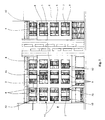
- FIG. 1 shows a view of a building with numerous assemblies provided in accordance with subject of the present invention
- FIG. 2 shows a schematic perspective view of an embodiment of the assembly according to the invention
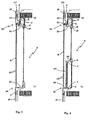
- FIGS. 3 and 4 show two vertically sectioned views of the assembly according to Figure 2 along the lines III-III and IV-IV, respectively, in locations where a door and a window with the internal fixture of the leaf type are installed;
- FIGS. 5 and 6 show two vertically sectioned views, in the locations of a door and window, of a further embodiment of the assembly according to the present invention with the framework closed in some areas with masonry parts of the wall;
- FIGS. 7 and 8 show two vertically sectioned views showing an open area and closed area of a further embodiment of the assembly according to the present invention having a concealable door as fixture;
- FIG. 9 shows a horizontally sectioned view of the assembly according to Figures 3 and 4;
- FIG. 10 shows a horizontally sectioned view of the assembly according to Figures 5 and 6;
- FIG. 11 shows a horizontally sectioned view of the assembly according to Figures 7 and 8;
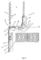
- FIGS. 12 and 13 show two enlarged details of Figure 3 relating to a top and bottom portion of the assembly
- FIG. 14 shows an enlarged detail of Figure 10 relating to a continuity panelling arranged so as to join together two adjacent assemblies
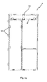
- FIGS. 15 and 16 show two enlarged details of the assembly according to the present invention relating to two supporting frames, one of which is associated with a door and the other with a window;
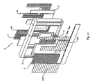
- FIG. 17 shows an exploded schematic view of a further embodiment of the assembly according to the present invention.
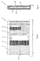
- FIGS. 18 and 19 show a front view and a vertically sectioned view along the line XIX-XIX of Figure 18 of the assembly according to Figure 17.
- 1 denotes in its entirety the fixture assembly for the building industry according to the present invention.
- the assembly 1 has a first side F1 intended to face the inside of the wall P of a building E and a second side F2 intended to face the outside of the same building E, as can be understood in particular from the illustration in Figure 1 which shows an entire building finished with the assembly 1 in question.
- the assembly 1 is structurally supported by a supporting framework 2 which consists of tubular iron profiles fixed together by brackets and reinforcing angle-irons and which is inset, as will be explained in detail below, during installation of the assembly 1 inside an opening formed in the masonry wall P of the building E and then fixed perimetrally in a manner traditional per se by means of steel clamps 50, screws or the like (not shown since of the type known per se) for securing to the masonry.
- a supporting framework 2 which consists of tubular iron profiles fixed together by brackets and reinforcing angle-irons and which is inset, as will be explained in detail below, during installation of the assembly 1 inside an opening formed in the masonry wall P of the building E and then fixed perimetrally in a manner traditional per se by means of steel clamps 50, screws or the like (not shown since of the type known per se) for securing to the masonry.
- the assembly 1 extends mainly in two perpendicular directions which, once it has been installed, corresponds to its width and its height and define an installation surface parallel to the masonry wall P.
- the thickness of the assembly 1 is intended to be inserted into the depth of the opening formed in the masonry wall P.
- the supporting framework 2 has substantially the shape of a surrounding frame with any reinforcing uprights or cross-members where possible and defines, once arranged inside the opening of the masonry wall, at least one closed area 3 arranged continuously with the surrounding masonry wall P and at least one open area 4 provided opposite a cavity 5 formed in the masonry wall P itself so as to allow the arrangement of a door or window suitable for establishing communication between the internal environment of the building E and the external environment.
- An internal fixture 6 consisting of a door or a window of the leaf, sliding, raising/sliding or concealable type is mounted on the first side F1 of the assembly.
- the internal fixture 6 consists of a fixed frame 6', which is mechanically mounted on the supporting framework 2 by means of an inner bracket system 7, and a movable frame 6" which, depending on the type of prechosen iron fitting, is rotatably connected to the fixed frame 6' by means of hinges or is slidably associated with the latter by means of a rail.
- a movable shutter 8 which is slidably connected to the supporting framework 2 by means of an outer bracket system 9, is mounted on the second side F2 of the assembly 1.
- the movable shutter 8 is advantageously formed by a plurality of directable (or fixed) horizontal-axis tongues which are pivotably mounted at their ends on two columns 8' supporting the shutter 8 (see Figures 9 and 11).
- the shutter 8 can be actuated to move, manually or by means of suitable drive means 11, in a manner parallel to the plane of installation and the wall P of the building, between a light-blocking position X1, where it is arranged mainly covering the open area 4 of the supporting framework 2, and a light-admitting position X2, where it is arranged mainly covering the closed area 3 of the said supporting framework 2.
- the supporting framework 2 is preferably arranged in an intermediate position between the internal fixture 6 and the external shutter 8 to which it is connected by means of the inner bracket system 7 and outer bracket system 9, respectively.
- the movable shutter 8 is connected to the supporting framework by means of guide means.
- These means comprise, in the upper part of the assembly 1, a rail 12 fixed by means of the outer bracket system 9 to a top upright 2' of the supporting framework 2 (see Figure 12).
- a carriage 14 is free to slide inside the rail 12, said carriage having two wheels and being mechanically connected to a profile 20 for supporting the shutter 8, arranged on the top side 15 of the latter. Therefore, in accordance with the preferred mechanical configuration, the shutter 8 is hung from the supporting framework 2.
- the shutter 8 may slide between the two positions X1, X2 mentioned above, resting on the supporting framework 2 along its bottom side 16.
- the guide means also comprise a bottom shaped profile 17 which is fixed to the supporting framework 2 by means of the outer bracket system 9 and defines a longitudinal guide seat 18 inside which a slide 19 formed in the bottom shaped profile 17 of the shutter 8 is free to slide.
- the drive means 11 may for example be in the form of a motor 21 or also a linear actuator which is fixed to the top upright 2' of the supporting framework 2 by means of the second bracket system 9 and mechanically connected by transmission means 22 to the profile 20 supporting the shutter 8.
- the transmission means 22 represented by a rack in the attached Figure 12 may similarly be formed by a toothed chain or by a belt mechanically associated with the profile 20 supporting the shutter 8.
- the assembly 1 comprises an outer panelling 23 which is fixed to the supporting framework 2 in the closed area 3 which is uncovered by the shutter 8 when the latter assumes the light-blocking position X1, as may be appreciated from outside the building E.
- the outer panelling 23 is a finishing and refining element of the assembly 1 which may be realized, depending on the various aesthetic and architectural requirements, using different materials including sheet metal (in particular aluminium), stone, wood, etc.
- this panelling is formed by shaped sheet-metal parts 23' (see Figure 8) which can be modularly combined so as to achieve the desired extended configurations or by a plurality of panels of another kind which are connected together mechanically in a continuous manner.
- an inner panelling 24 for example made of plasterboard or some other finishing element is mounted on the latter.
- this panelling 24 is secured to the supporting framework 2 by means of shims or stoppers S able to ensure its alignment with the face of the inner wall of the building E.
- Insulating material C is arranged between the outer panelling 23 and the inner panelling 24.
- Radiating panels 60 may be arranged between the two said panels 23 and 24 and preferably against the inner panelling 24 or even in place of the latter, as shown in Figure 17 where it has been assumed that the radiating panelling is on the inner visible side if necessary covered by a layer of paint or other finishing layers.
- the radiating panels 60 By arranging the radiating panels 60 in the closed area 3 of the assembly 1, it is possible to optimize advantageously use of the spaces, allowing an element, i.e. the radiating panel 60, to be housed inside the wall P, said panel being normally arranged inside the rooms of the building, which results in the often undesirable occupation of space.
- the outer panelling 23 may be realized in the form of solar panels 23" for recycling the incident solar energy.
- solar panels must be understood as meaning both those panels designed to produce electric energy by means of systems which convert the solar energy via photovoltaic cells capable of transforming electromagnetic power or the sun light into electricity, owing to the chemical/physical properties of the material from which the cells are made, and also thermal solar panels designed to heat sanitary water for daily use without using gas or electricity and which allow replacement, at least partly, of the electric water heater or gas boiler in order to obtain hot water for washing plates, showering, bathroom use, etc.
- the abovementioned outer panelling 23 comprising solar panels will preferably be arranged in front of the shutter 8 so as not to be obscured by the latter when the said shutter 8 moves into the light-admitting position X2 covering the closed area 3 of the supporting framework 2.
- the shutter will still move so as to cover the closed area 3 of the supporting framework 2, but is inserted, however, behind the outer panelling 23.
- the supporting framework 2 will be situated more off-centre towards the second side of the assembly 1 and will have advantageously a cross-sectional profile which becomes thinner along the plane of lie in order to reduce the projection of the assembly 1 towards the outside of the masonry wall P.
- an empty chamber 25 is formed between the abovementioned outer panelling 23 and inner panelling 24 in the closed area 3 of the supporting framework 2.
- This chamber 25 is able to house a concealable leaf 26 of the internal fixture 6.
- This leaf 26 is able to slide between a closed position, where it faces the open area 4 of the supporting framework 2, and open position, where it is inserted inside the chamber 25.
- the assembly 1 has an appreciable aesthetic effect in particular when it is inserted inside the opening formed in the wall P of the building E with the shutter 8 arranged substantially in the plane of lie of the outer surface of the masonry wall P substantially continuously with the latter and partially defining the second side F2 of the assembly 1.
- the assembly 1 with a thickness such that it is inset completely with the shutter 8 flush with the outer surface of the wall P, namely provide on the outer wall P an outer cladding R advantageously consisting of panels R' fixed to the masonry wall P by means of a connecting bracket system 27 or ventilating panels R" connected to the masonry walls P by means of transmission means 27' of the type known per se.
- Figure 2 shows an assembly which is provided with a single supporting framework 2 able to accommodate two internal fixtures 6 consisting of a door and a window and two associated outer shutters 8.
- assemblies 1 may be realized by connecting together in a modular manner various different assemblies each associated with a single inner shutter 6 and a single outer shutter 8.
- Figures 15 and 16 show two plan views of two supporting frameworks 2, the first one relating to an assembly associated with a door with associated outer shutter and the second one relating to a window with associated outer shutter.
- the supporting framework 2 is an essential element of the present invention since it allows the outer shutter 8 and the inner shutter 6 to be combined structurally in a single self-supporting assembly in the manner of an independent unit.
- the assemblies 1 are in fact particularly suitable for combination in a modular manner with other assemblies 1 associated with the same or different fixtures 6 and 8.
- a continuity panelling 28 is envisaged, this consisting for example of individual modular sheet-metal panels preferably made of aluminium and shaped so as to extend and connect together the supporting frames 2 of adjacent assemblies, as can be seen in the overall view shown in Figure 1, where this panelling 28 is shown arranged so as to surround and join together the various assemblies 1, or in the particular illustration shown in Figure 14, which shows the profile of the continuity panelling 28 enabling the joining together of several panels.
- the inner bracket system 7 and outer bracket system 9 of the supporting framework 2 is lined with covering profiles or "mouldings" 30 consisting, for example, of sheet-metal panels obtained by means of extrusion or folding.
- the covering profiles 30 have an aesthetic lining function and therefore may be made using the most appropriate materials, shapes and colours.
- the assembly 1 may be realized in different sizes and in particular, in accordance with the embodiment shown in Figures 3, 4, 7, 8, 12 and 13, may extend from the ground level T1 to the ceiling level T2, therefore covering the whole height of a storey of the building E.
- the supporting framework 2 extends above the shutter 8 of the fixture 6 and is closed by means of an inner closing panelling 40 and outer closing panelling 50, as can be seen in Figure 50, where the outer panelling 50 is simply formed by insulation material C since an outer cladding R is furthermore envisaged.
- the present invention also relates to a method for installing the assembly 1 for the building industry described above.
- This method consists of a step involving preparation of the assembly where, by means of the inner bracket system 7 and outer bracket system 9, the internal frame and the shutter 8 are joined together on the first side F1.
- the fixed frame 6' is merely fixed, without already arranging the movable frame 6" which may be easily and rapidly mounted subsequently and which could be damaged during installation of the assembly 1.
- the outer panelling 23 and the inner panelling 24 and preferably also all the covering profiles 30 will also be arranged in position.
- the invention thus conceived therefore achieves the predetermined objects.
Landscapes
- Engineering & Computer Science (AREA)
- Civil Engineering (AREA)
- Structural Engineering (AREA)
- Building Environments (AREA)
Abstract
Description
- Technical sector
- The present invention concerns a fixture assembly for the building industry and a method for the installation thereof.
- The assembly in question is intended to be advantageously used as a separate element or modularly associated with other assemblies for the formation of external and internal fixtures having a finishing or protective function for buildings of any kind such as, for example, houses, large buildings, blocks of flats, skyscrapers, etc.
- The method for installation of the fixture assembly is particularly suitable for use in the construction of buildings by construction companies.
- Background art
- In the first half of the 19th century the development of steel technology led, in certain areas of constructional and architectural design, to a transition from traditional well-established masonry structures to a new approach in the use of space and at the same time it became possible to realize external facades completely formed by glass panels arranged alongside each other.
- More recently glass panels consisting of a support structure supporting internally one or more windows have been developed, said panels being designed to be arranged modularly together with other panels in special spaces provided in the walls of a building undergoing construction.
- The glass panels currently available on the market are independent elements which cannot be combined structurally and functionally with the internal fixtures, such as the traditional frames of doors and windows and with the external fixtures, such as the shutters.
- The fixtures of the traditional type for masonry structures do not allow the construction of building walls by combining together modular elements and therefore do not allow flexible architectural design of the facades.
- Moreover, the installation of internal and external fixtures requires the use of a large amount of labour and fairly long execution times.
- Disclosure of the invention
- The main object of the present invention is therefore that of eliminating the drawbacks of glass panels of the type mentioned above, by providing a fixture assembly for the building industry which is simple and versatile to use, thereby drastically reducing the time currently required for installation of the internal and external fixtures.
- Another object of the present invention is that of providing an assembly for the building industry which is able to satisfy the various needs of interior and exterior architectural design.
- A further object of the present invention is that of providing an assembly for the building industry which is constructionally simple and inexpensive to manufacture and operationally entirely reliable.
- Another object of the present invention is that of providing of a method for installation of the assembly for the building industry which is quick and simple.
- Brief description of the drawings
- The technical features of the invention, in accordance with the abovementioned objects, may be clearly understood from the content of the claims indicated below and the advantages thereof will emerge more clearly from the detailed description which follows, provided with reference to the accompanying drawings which illustrate a purely exemplary and non-limiting example of embodiment in which:
- FIG. 1 shows a view of a building with numerous assemblies provided in accordance with subject of the present invention;
- FIG. 2 shows a schematic perspective view of an embodiment of the assembly according to the invention;
- FIGS. 3 and 4 show two vertically sectioned views of the assembly according to Figure 2 along the lines III-III and IV-IV, respectively, in locations where a door and a window with the internal fixture of the leaf type are installed;
- FIGS. 5 and 6 show two vertically sectioned views, in the locations of a door and window, of a further embodiment of the assembly according to the present invention with the framework closed in some areas with masonry parts of the wall;
- FIGS. 7 and 8 show two vertically sectioned views showing an open area and closed area of a further embodiment of the assembly according to the present invention having a concealable door as fixture;
- FIG. 9 shows a horizontally sectioned view of the assembly according to Figures 3 and 4;
- FIG. 10 shows a horizontally sectioned view of the assembly according to Figures 5 and 6;
- FIG. 11 shows a horizontally sectioned view of the assembly according to Figures 7 and 8;
- FIGS. 12 and 13 show two enlarged details of Figure 3 relating to a top and bottom portion of the assembly;
- FIG. 14 shows an enlarged detail of Figure 10 relating to a continuity panelling arranged so as to join together two adjacent assemblies;
- FIGS. 15 and 16 show two enlarged details of the assembly according to the present invention relating to two supporting frames, one of which is associated with a door and the other with a window;
- FIG. 17 shows an exploded schematic view of a further embodiment of the assembly according to the present invention;
- FIGS. 18 and 19 show a front view and a vertically sectioned view along the line XIX-XIX of Figure 18 of the assembly according to Figure 17.
- Detailed description of a preferred example of embodiment
- With reference to the accompanying drawings, 1 denotes in its entirety the fixture assembly for the building industry according to the present invention.
- The
assembly 1 has a first side F1 intended to face the inside of the wall P of a building E and a second side F2 intended to face the outside of the same building E, as can be understood in particular from the illustration in Figure 1 which shows an entire building finished with theassembly 1 in question. - The
assembly 1 is structurally supported by a supportingframework 2 which consists of tubular iron profiles fixed together by brackets and reinforcing angle-irons and which is inset, as will be explained in detail below, during installation of theassembly 1 inside an opening formed in the masonry wall P of the building E and then fixed perimetrally in a manner traditional per se by means ofsteel clamps 50, screws or the like (not shown since of the type known per se) for securing to the masonry. - The
assembly 1 extends mainly in two perpendicular directions which, once it has been installed, corresponds to its width and its height and define an installation surface parallel to the masonry wall P. The thickness of theassembly 1 is intended to be inserted into the depth of the opening formed in the masonry wall P. - The supporting
framework 2 has substantially the shape of a surrounding frame with any reinforcing uprights or cross-members where possible and defines, once arranged inside the opening of the masonry wall, at least one closedarea 3 arranged continuously with the surrounding masonry wall P and at least oneopen area 4 provided opposite acavity 5 formed in the masonry wall P itself so as to allow the arrangement of a door or window suitable for establishing communication between the internal environment of the building E and the external environment. - An
internal fixture 6 consisting of a door or a window of the leaf, sliding, raising/sliding or concealable type is mounted on the first side F1 of the assembly. - In greater detail, the
internal fixture 6 consists of a fixed frame 6', which is mechanically mounted on the supportingframework 2 by means of an inner bracket system 7, and amovable frame 6" which, depending on the type of prechosen iron fitting, is rotatably connected to the fixed frame 6' by means of hinges or is slidably associated with the latter by means of a rail. - A
movable shutter 8, which is slidably connected to the supportingframework 2 by means of anouter bracket system 9, is mounted on the second side F2 of theassembly 1. - The
movable shutter 8 is advantageously formed by a plurality of directable (or fixed) horizontal-axis tongues which are pivotably mounted at their ends on two columns 8' supporting the shutter 8 (see Figures 9 and 11). - The
shutter 8 can be actuated to move, manually or by means of suitable drive means 11, in a manner parallel to the plane of installation and the wall P of the building, between a light-blocking position X1, where it is arranged mainly covering theopen area 4 of the supportingframework 2, and a light-admitting position X2, where it is arranged mainly covering the closedarea 3 of the said supportingframework 2. - The supporting
framework 2 is preferably arranged in an intermediate position between theinternal fixture 6 and theexternal shutter 8 to which it is connected by means of the inner bracket system 7 andouter bracket system 9, respectively. - In accordance with a preferred embodiment of the present invention, the
movable shutter 8 is connected to the supporting framework by means of guide means. - These means comprise, in the upper part of the
assembly 1, arail 12 fixed by means of theouter bracket system 9 to a top upright 2' of the supporting framework 2 (see Figure 12). Acarriage 14 is free to slide inside therail 12, said carriage having two wheels and being mechanically connected to aprofile 20 for supporting theshutter 8, arranged on thetop side 15 of the latter. Therefore, in accordance with the preferred mechanical configuration, theshutter 8 is hung from the supportingframework 2. - Obviously, without thereby departing from the scope of protection of the present patent, the
shutter 8 may slide between the two positions X1, X2 mentioned above, resting on the supportingframework 2 along itsbottom side 16. - Advantageously, in order to prevent fluttering of the
shutter 8, the guide means also comprise a bottomshaped profile 17 which is fixed to the supportingframework 2 by means of theouter bracket system 9 and defines alongitudinal guide seat 18 inside which aslide 19 formed in the bottomshaped profile 17 of theshutter 8 is free to slide. - The drive means 11 may for example be in the form of a
motor 21 or also a linear actuator which is fixed to the top upright 2' of the supportingframework 2 by means of thesecond bracket system 9 and mechanically connected by transmission means 22 to theprofile 20 supporting theshutter 8. - The transmission means 22 represented by a rack in the attached Figure 12 may similarly be formed by a toothed chain or by a belt mechanically associated with the
profile 20 supporting theshutter 8. - The
assembly 1 according to the invention comprises anouter panelling 23 which is fixed to the supportingframework 2 in the closedarea 3 which is uncovered by theshutter 8 when the latter assumes the light-blocking position X1, as may be appreciated from outside the building E. - Therefore, the
outer panelling 23 is a finishing and refining element of theassembly 1 which may be realized, depending on the various aesthetic and architectural requirements, using different materials including sheet metal (in particular aluminium), stone, wood, etc. - Advantageously, this panelling is formed by shaped sheet-metal parts 23' (see Figure 8) which can be modularly combined so as to achieve the desired extended configurations or by a plurality of panels of another kind which are connected together mechanically in a continuous manner.
- On the inner side F1 of the
assembly 1 facing the inside of the building E covering the said closedarea 3 of the supportingframework 2, aninner panelling 24 for example made of plasterboard or some other finishing element is mounted on the latter. - Preferably, this
panelling 24 is secured to the supportingframework 2 by means of shims or stoppers S able to ensure its alignment with the face of the inner wall of the building E. - Insulating material C is arranged between the
outer panelling 23 and theinner panelling 24. -
Radiating panels 60 may be arranged between the two saidpanels inner panelling 24 or even in place of the latter, as shown in Figure 17 where it has been assumed that the radiating panelling is on the inner visible side if necessary covered by a layer of paint or other finishing layers. - By arranging the
radiating panels 60 in the closedarea 3 of theassembly 1, it is possible to optimize advantageously use of the spaces, allowing an element, i.e. theradiating panel 60, to be housed inside the wall P, said panel being normally arranged inside the rooms of the building, which results in the often undesirable occupation of space. - Alternatively or equally well the
outer panelling 23 may be realized in the form ofsolar panels 23" for recycling the incident solar energy. - The term "solar panels" must be understood as meaning both those panels designed to produce electric energy by means of systems which convert the solar energy via photovoltaic cells capable of transforming electromagnetic power or the sun light into electricity, owing to the chemical/physical properties of the material from which the cells are made, and also thermal solar panels designed to heat sanitary water for daily use without using gas or electricity and which allow replacement, at least partly, of the electric water heater or gas boiler in order to obtain hot water for washing plates, showering, bathroom use, etc.
- In accordance with a possible embodiment of the present invention, in order to optimize recycling of the solar energy, the abovementioned
outer panelling 23 comprising solar panels will preferably be arranged in front of theshutter 8 so as not to be obscured by the latter when the saidshutter 8 moves into the light-admitting position X2 covering the closedarea 3 of the supportingframework 2. - In this case the abovementioned guide means will be provided behind the
outer panelling 23 as can be understood from the illustration in Figure 18 where the shutters are in an intermediate position between the end positions X1 and X2 considered above and from the illustration in Figure 19 which shows a vertically sectioned schematic view of the illustration in Figure 18. - Therefore, in this embodiment the shutter will still move so as to cover the closed
area 3 of the supportingframework 2, but is inserted, however, behind theouter panelling 23. - If it should not be possible for constructional reasons to form an opening in the masonry wall P of the building E completely passing through the masonry over the whole extension of the
open area 4 and the closedarea 3, then theouter panelling 23 will no longer cover an insulating filling C, but a masonry portion M of the wall P as shown in the embodiment of theassembly 1 illustrated in Figures 6 and 10. - In this case, the supporting
framework 2 will be situated more off-centre towards the second side of theassembly 1 and will have advantageously a cross-sectional profile which becomes thinner along the plane of lie in order to reduce the projection of theassembly 1 towards the outside of the masonry wall P. - In the embodiment of the
assembly 1 considered, however, in Figures 8 and 11, anempty chamber 25 is formed between the abovementionedouter panelling 23 andinner panelling 24 in theclosed area 3 of the supportingframework 2. - This
chamber 25 is able to house aconcealable leaf 26 of theinternal fixture 6. - This
leaf 26 is able to slide between a closed position, where it faces theopen area 4 of the supportingframework 2, and open position, where it is inserted inside thechamber 25. - The
assembly 1 has an appreciable aesthetic effect in particular when it is inserted inside the opening formed in the wall P of the building E with theshutter 8 arranged substantially in the plane of lie of the outer surface of the masonry wall P substantially continuously with the latter and partially defining the second side F2 of theassembly 1. - In order to achieve this, it is possible to form the
assembly 1 with a thickness such that it is inset completely with theshutter 8 flush with the outer surface of the wall P, namely provide on the outer wall P an outer cladding R advantageously consisting of panels R' fixed to the masonry wall P by means of a connectingbracket system 27 or ventilating panels R" connected to the masonry walls P by means of transmission means 27' of the type known per se. - Figure 2 shows an assembly which is provided with a single supporting
framework 2 able to accommodate twointernal fixtures 6 consisting of a door and a window and two associatedouter shutters 8. - Obviously, without departing from the scope of protection of the present patent, the
assemblies 1 may be realized by connecting together in a modular manner various different assemblies each associated with a singleinner shutter 6 and a singleouter shutter 8. - For this purpose, Figures 15 and 16 show two plan views of two supporting
frameworks 2, the first one relating to an assembly associated with a door with associated outer shutter and the second one relating to a window with associated outer shutter. - The supporting
framework 2 is an essential element of the present invention since it allows theouter shutter 8 and theinner shutter 6 to be combined structurally in a single self-supporting assembly in the manner of an independent unit. - In Figures 15 and 16 the
clamps 50 for performing fixing to the masonry wall P of the building E are particularly visible. - The
assemblies 1 are in fact particularly suitable for combination in a modular manner withother assemblies 1 associated with the same ordifferent fixtures - For this purpose, a
continuity panelling 28 is envisaged, this consisting for example of individual modular sheet-metal panels preferably made of aluminium and shaped so as to extend and connect together the supportingframes 2 of adjacent assemblies, as can be seen in the overall view shown in Figure 1, where thispanelling 28 is shown arranged so as to surround and join together thevarious assemblies 1, or in the particular illustration shown in Figure 14, which shows the profile of thecontinuity panelling 28 enabling the joining together of several panels. - The inner bracket system 7 and
outer bracket system 9 of the supportingframework 2 is lined with covering profiles or "mouldings" 30 consisting, for example, of sheet-metal panels obtained by means of extrusion or folding. The covering profiles 30 have an aesthetic lining function and therefore may be made using the most appropriate materials, shapes and colours. - The
assembly 1 may be realized in different sizes and in particular, in accordance with the embodiment shown in Figures 3, 4, 7, 8, 12 and 13, may extend from the ground level T1 to the ceiling level T2, therefore covering the whole height of a storey of the building E. - For this purpose, the supporting
framework 2 extends above theshutter 8 of thefixture 6 and is closed by means of aninner closing panelling 40 andouter closing panelling 50, as can be seen in Figure 50, where theouter panelling 50 is simply formed by insulation material C since an outer cladding R is furthermore envisaged. - The present invention also relates to a method for installing the
assembly 1 for the building industry described above. - This method consists of a step involving preparation of the assembly where, by means of the inner bracket system 7 and
outer bracket system 9, the internal frame and theshutter 8 are joined together on the first side F1. - Preferably, during this step, the fixed frame 6' is merely fixed, without already arranging the
movable frame 6" which may be easily and rapidly mounted subsequently and which could be damaged during installation of theassembly 1. - In a similar manner, with regard to the
shutter 8, it must be understood preferably that, during preparation, all the fixed components intended to be mechanically connected to theshutter 8 are solely assembled, and the latter, for the same reasons as themovable leaf 6", may be rapidly mounted on the assembly only subsequently. - Therefore, initially it is possible to perform during this step solely assembly of the fixed elements, namely for example the bottom shaped
profile 17, fixing it to the supportingframework 2 by means of theouter bracket system 9, and therail 12, fixing it by means of theouter bracket system 9 to the upper bracket system 2' of the supportingframework 2. - During this step the
outer panelling 23 and theinner panelling 24 and preferably also all the covering profiles 30 will also be arranged in position. - At this point it is possible to perform installation of the
assembly 1 inside the opening formed in the masonry wall P of the building E, followed by a step for perimetral fixing of the supportingframework 2 of theassembly 1 to the masonry wall P. - During a subsequent finishing step it will then be possible to arrange in position the movable parts, that is the
movable frame 6" and themovable shutter 8 as well as the cladding panels R and thecontinuity panels 28. - The invention thus conceived therefore achieves the predetermined objects.
- Obviously it may also assume, during its practical realization, also forms and configurations different from that illustrated above without thereby departing from the present scope of protection.
- Moreover, all the details may be replaced by technically equivalent elements, and the dimensions, the forms and the materials used may be of any nature according to requirements.
Claims (23)
- Fixture assembly for the building industry, having a first side intended to face the inside of a building and a second side intended to face the outside of the same building, characterized in that it comprises:- a supporting framework which is able to be fixed perimetrally inside an opening formed in the masonry wall of said building and which defines an installation plane parallel to said masonry wall and delimits at least one closed area intended to be arranged continuously with said masonry wall and at least one open area intended to be arranged opposite a cavity formed in said masonry wall;- an internal fixture, in particular of a door or a window, which is mechanically connected to said supporting framework on the first side of the assembly;- a movable shutter slidably connected to said supporting framework on the second side of said assembly and able to be actuated so as to move, parallel to said installation plane, between a light-blocking position, where it is arranged mainly covering the open area of said supporting framework, and a light-admitting position, where it is arranged mainly covering the closed area of said supporting framework.
- Assembly according to Claim 1, characterized in that said internal fixture is connected to said supporting framework by means of an inner bracket system.
- Assembly according to Claim 1, characterized in that said shutter is connected to said supporting framework by means of guide means comprising at least one rail inside which a carriage mechanically connected to said shutter is free to slide.
- Assembly according to Claim 3, characterized in that said rail is fixed to a top upright of said supporting framework by means of an outer bracket system for supporting said shutter in a hung manner.
- Assembly according to Claim 3, characterized in that said guide means comprise a bottom shaped profile having a longitudinal guide seat inside which a slide mechanically connected to said shutter is free to slide, said bottom shaped profile being fixed to a bottom side of said supporting framework by means of an outer bracket system.
- Assembly according to any one of the preceding claims, characterized in that it comprises drive means for moving said shutter between said light-blocking position and said light-admitting position.
- Assembly according to Claims 6 and 4, characterized in that said drive means comprise at least one motor or a linear actuator fixed to the top upright of said supporting framework by means of said outer bracket system, which is mechanically connected by transmission means to a profile supporting said shutter.
- Assembly according to Claim 7, characterized in that said transmission means comprise a rack or a toothed chain or a belt mechanically associated with the profile supporting said shutter.
- Assembly according to Claim 1, characterized in that it comprises at least one outer panelling fixed to said framework in said closed area by way of partial definition of said second side of the assembly facing the outside of the building.
- Assembly according to Claim 9, characterized in that said outer panelling is realized in the form of a modular combinable sheet-metal element or by a plurality of panels which are connected together.
- Assembly according to Claim 9 or 10, characterized in that said outer panelling is able to be arranged so as to cover a portion of said masonry wall.
- Assembly according to Claim 1, characterized in that it comprises at least one inner panelling fixed to said framework in said closed area so as to partially define said first side of the assembly facing the inside of the building.
- Assembly according to Claim 9 and 12, characterized in that a chamber is formed between said inner panelling and outer panelling and in that said internal fixture comprises a concealable leaf able to slide between a closing position, where it faces the open area of said supporting framework, and an open position, where it is inserted inside said chamber.
- Assembly according to any one of the preceding claims, characterized in that said shutter is arranged substantially in the plane of lie defined by the second side of said assembly intended to face the outside of the building in a substantially continuous manner with the external surface of said masonry wall.
- Assembly according to any one of the preceding claims, characterized in that it may be modularly combined with other assemblies, a continuity panel being envisaged for connecting together the frames of adjacent assemblies.
- Assembly according to any one of the preceding claims, characterized in that said framework extends substantially from the floor level to the ceiling level of a storey of said building, an inner and an outer closing panelling being envisaged above said shutter and said fixture.
- Assembly according to Claim 9 and 12, characterized in that insulating material is arranged between said inner and outer panelling.
- Assembly according to Claim 9 and 12, characterized in that a radiating panelling is envisaged between said inner and outer panelling or in place of said inner panelling.
- Assembly according to Claim 9, characterized in that said outer panelling consists of solar panels for recycling the solar energy.
- Assembly according to Claim 9, characterized in that said outer panelling consists of solar panels for recycling the solar energy.
- Assembly according to Claim 20, characterized in that said shutter 8 is supported by said guide means in said light-admitting position so as to cover said closed area 3 of the supporting framework 2 behind said outer panelling 23 comprising solar panels.
- Method for installation of a fixture assembly for the building industry according to Claim 1, which envisages the following operative steps:- a step involving preparation of the assembly with at least partially mounted on said supporting framework and on its first side said internal fixture and on its second side said movable shutter, i.e. the fixed components of said internal fixture and said movable shutter;- a step involving installation of said assembly inside an opening formed in the masonry wall of a building;- a step involving perimetral fixing of the supporting framework 2 of said assembly to said masonry wall.
- Method according to Claims 9, 12 and 22, characterized in that outer panelling, inner panelling and preferably covering profiles are mounted during said preparation step.
Applications Claiming Priority (1)
| Application Number | Priority Date | Filing Date | Title |
|---|---|---|---|
| ITPD20050057 ITPD20050057A1 (en) | 2005-03-02 | 2005-03-02 | FAST ASSEMBLY FOR BUILDING AND PROCEDURE FOR ITS APPLICATION |
Publications (1)
| Publication Number | Publication Date |
|---|---|
| EP1698754A1 true EP1698754A1 (en) | 2006-09-06 |
Family
ID=34956583
Family Applications (1)
| Application Number | Title | Priority Date | Filing Date |
|---|---|---|---|
| EP06075483A Withdrawn EP1698754A1 (en) | 2005-03-02 | 2006-03-02 | Fixture assembly for the building industry and method for the installation thereof |
Country Status (2)
| Country | Link |
|---|---|
| EP (1) | EP1698754A1 (en) |
| IT (1) | ITPD20050057A1 (en) |
Cited By (4)
| Publication number | Priority date | Publication date | Assignee | Title |
|---|---|---|---|---|
| WO2009053507A1 (en) * | 2007-10-25 | 2009-04-30 | Blanca Lleó Asociados, S.L. | Facade system comprising sun tracking slats |
| ITLI20120011A1 (en) * | 2012-10-23 | 2014-04-24 | D Ancona Pier Lorenzo Levi | CASCO ASSEMBLED WITH DRY PANEL AND VENTILATED ROOF PANELS. |
| EP2781680A2 (en) | 2013-03-19 | 2014-09-24 | Brose Fahrzeugteile GmbH & Co. KG, Coburg | Pre-assembled modular unit of a closing device of a building |
| CN112482611A (en) * | 2020-12-25 | 2021-03-12 | 陕西理工大学 | Novel building greening outer wall |
Families Citing this family (1)
| Publication number | Priority date | Publication date | Assignee | Title |
|---|---|---|---|---|
| CN110185177B (en) * | 2019-06-25 | 2024-01-30 | 中联西北工程设计研究院有限公司 | Cavity curtain wall capable of folding and changing |
Citations (1)
| Publication number | Priority date | Publication date | Assignee | Title |
|---|---|---|---|---|
| US4821475A (en) * | 1986-09-08 | 1989-04-18 | Yoshida Kogyo K. K. | Duct mounting structure for prefabricated curtain wall with air conditioning system |
-
2005
- 2005-03-02 IT ITPD20050057 patent/ITPD20050057A1/en unknown
-
2006
- 2006-03-02 EP EP06075483A patent/EP1698754A1/en not_active Withdrawn
Patent Citations (1)
| Publication number | Priority date | Publication date | Assignee | Title |
|---|---|---|---|---|
| US4821475A (en) * | 1986-09-08 | 1989-04-18 | Yoshida Kogyo K. K. | Duct mounting structure for prefabricated curtain wall with air conditioning system |
Cited By (7)
| Publication number | Priority date | Publication date | Assignee | Title |
|---|---|---|---|---|
| WO2009053507A1 (en) * | 2007-10-25 | 2009-04-30 | Blanca Lleó Asociados, S.L. | Facade system comprising sun tracking slats |
| ES2322748A1 (en) * | 2007-10-25 | 2009-06-25 | Blanca Lleo Asociados, S.L. | Facade system comprising sun tracking slats |
| ES2322748B1 (en) * | 2007-10-25 | 2010-04-20 | Blanca Lleo Asociados, S.L. | SOLAR FOLLOWING FACADE SYSTEM. |
| ITLI20120011A1 (en) * | 2012-10-23 | 2014-04-24 | D Ancona Pier Lorenzo Levi | CASCO ASSEMBLED WITH DRY PANEL AND VENTILATED ROOF PANELS. |
| EP2781680A2 (en) | 2013-03-19 | 2014-09-24 | Brose Fahrzeugteile GmbH & Co. KG, Coburg | Pre-assembled modular unit of a closing device of a building |
| DE102013204796A1 (en) | 2013-03-19 | 2014-09-25 | Brose Fahrzeugteile Gmbh & Co. Kg, Coburg | Pre-assembled unit of a closing device of a building |
| CN112482611A (en) * | 2020-12-25 | 2021-03-12 | 陕西理工大学 | Novel building greening outer wall |
Also Published As
| Publication number | Publication date |
|---|---|
| ITPD20050057A1 (en) | 2006-09-03 |
Similar Documents
| Publication | Publication Date | Title |
|---|---|---|
| AU2018267564B2 (en) | Modular integrated building and construction method thereof | |
| CN101163842A (en) | Seismic safe and fire resistant edge compatible, non-block glazing | |
| WO2013166834A1 (en) | Combined building structure, installation method, house and toilet | |
| CN113039064A (en) | Modular building system | |
| AU2006299200A1 (en) | Mobile partition | |
| KR20140044450A (en) | Renovation process for improving the performance of the curtain wall insulation soundproof, and splice window | |
| RU2599243C1 (en) | System of construction translucent walling structures | |
| EP1698754A1 (en) | Fixture assembly for the building industry and method for the installation thereof | |
| DK2435639T3 (en) | Movable exterior wall system and method of incorporating it in an existing building | |
| US20250052053A1 (en) | Stackable and Road-Transportable Micro Modular House | |
| FI127802B (en) | Method for constructing a building | |
| JP6751389B2 (en) | Improvements in buildings | |
| AU2014270385A1 (en) | Invisible window frames | |
| NL2017217B1 (en) | Facade construction, as well as method for building and / or renovating houses. | |
| JP7017615B2 (en) | Wall structure | |
| CN212201844U (en) | Hidden electric roller shutter mounting system for toilet | |
| JP7724134B2 (en) | Building materials | |
| JP7752026B2 (en) | Exterior wall panels and installation methods for exterior wall panels | |
| JP7742279B2 (en) | Building materials | |
| CN115341780A (en) | Method for performing curtain wall transformation on outer wall surface of window wall structure | |
| JP7748852B2 (en) | Fixtures and maintenance methods | |
| CN115653475A (en) | Integrated sunshade door and window roller shutter system and installation method | |
| JP7748853B2 (en) | Building materials | |
| KR20190025293A (en) | Movable buildings and methods of construction | |
| CN222667042U (en) | An openable enclosed balcony structure, system and building |
Legal Events
| Date | Code | Title | Description |
|---|---|---|---|
| PUAI | Public reference made under article 153(3) epc to a published international application that has entered the european phase |
Free format text: ORIGINAL CODE: 0009012 |
|
| AK | Designated contracting states |
Kind code of ref document: A1 Designated state(s): AT BE BG CH CY CZ DE DK EE ES FI FR GB GR HU IE IS IT LI LT LU LV MC NL PL PT RO SE SI SK TR |
|
| AX | Request for extension of the european patent |
Extension state: AL BA HR MK YU |
|
| 17P | Request for examination filed |
Effective date: 20061218 |
|
| AKX | Designation fees paid |
Designated state(s): AT BE BG CH CY CZ DE DK EE ES FI FR GB GR HU IE IS IT LI LT LU LV MC NL PL PT RO SE SI SK TR |
|
| GRAP | Despatch of communication of intention to grant a patent |
Free format text: ORIGINAL CODE: EPIDOSNIGR1 |
|
| STAA | Information on the status of an ep patent application or granted ep patent |
Free format text: STATUS: THE APPLICATION IS DEEMED TO BE WITHDRAWN |
|
| 18D | Application deemed to be withdrawn |
Effective date: 20100408 |