EP2781290A1 - Drehmomentübertragungseinrichtung mit Fliehkraftpendel - Google Patents
Drehmomentübertragungseinrichtung mit Fliehkraftpendel Download PDFInfo
- Publication number
- EP2781290A1 EP2781290A1 EP14160419.9A EP14160419A EP2781290A1 EP 2781290 A1 EP2781290 A1 EP 2781290A1 EP 14160419 A EP14160419 A EP 14160419A EP 2781290 A1 EP2781290 A1 EP 2781290A1
- Authority
- EP
- European Patent Office
- Prior art keywords
- transmission device
- torque transmission
- flange
- axial projection
- disc part
- Prior art date
- Legal status (The legal status is an assumption and is not a legal conclusion. Google has not performed a legal analysis and makes no representation as to the accuracy of the status listed.)
- Granted
Links
Images


Classifications
-
- F—MECHANICAL ENGINEERING; LIGHTING; HEATING; WEAPONS; BLASTING
- F16—ENGINEERING ELEMENTS AND UNITS; GENERAL MEASURES FOR PRODUCING AND MAINTAINING EFFECTIVE FUNCTIONING OF MACHINES OR INSTALLATIONS; THERMAL INSULATION IN GENERAL
- F16F—SPRINGS; SHOCK-ABSORBERS; MEANS FOR DAMPING VIBRATION
- F16F15/00—Suppression of vibrations in systems; Means or arrangements for avoiding or reducing out-of-balance forces, e.g. due to motion
- F16F15/10—Suppression of vibrations in rotating systems by making use of members moving with the system
- F16F15/14—Suppression of vibrations in rotating systems by making use of members moving with the system using masses freely rotating with the system, i.e. uninvolved in transmitting driveline torque, e.g. rotative dynamic dampers
- F16F15/1407—Suppression of vibrations in rotating systems by making use of members moving with the system using masses freely rotating with the system, i.e. uninvolved in transmitting driveline torque, e.g. rotative dynamic dampers the rotation being limited with respect to the driving means
- F16F15/145—Masses mounted with play with respect to driving means thus enabling free movement over a limited range
-
- F—MECHANICAL ENGINEERING; LIGHTING; HEATING; WEAPONS; BLASTING
- F16—ENGINEERING ELEMENTS AND UNITS; GENERAL MEASURES FOR PRODUCING AND MAINTAINING EFFECTIVE FUNCTIONING OF MACHINES OR INSTALLATIONS; THERMAL INSULATION IN GENERAL
- F16F—SPRINGS; SHOCK-ABSORBERS; MEANS FOR DAMPING VIBRATION
- F16F15/00—Suppression of vibrations in systems; Means or arrangements for avoiding or reducing out-of-balance forces, e.g. due to motion
- F16F15/10—Suppression of vibrations in rotating systems by making use of members moving with the system
- F16F15/12—Suppression of vibrations in rotating systems by making use of members moving with the system using elastic members or friction-damping members, e.g. between a rotating shaft and a gyratory mass mounted thereon
- F16F15/131—Suppression of vibrations in rotating systems by making use of members moving with the system using elastic members or friction-damping members, e.g. between a rotating shaft and a gyratory mass mounted thereon the rotating system comprising two or more gyratory masses
-
- F—MECHANICAL ENGINEERING; LIGHTING; HEATING; WEAPONS; BLASTING
- F16—ENGINEERING ELEMENTS AND UNITS; GENERAL MEASURES FOR PRODUCING AND MAINTAINING EFFECTIVE FUNCTIONING OF MACHINES OR INSTALLATIONS; THERMAL INSULATION IN GENERAL
- F16F—SPRINGS; SHOCK-ABSORBERS; MEANS FOR DAMPING VIBRATION
- F16F2226/00—Manufacturing; Treatments
- F16F2226/04—Assembly or fixing methods; methods to form or fashion parts
Definitions
- the invention relates to a torque transmission device arranged around an axis of rotation between an internal combustion engine and a transmission of a motor vehicle with a centrifugal pendulum accommodated on a disk part, comprising a flange part and a plurality of pendulum masses distributed over the circumference and limitedly pivotably received therein.
- Torque transmission devices between an internal combustion engine and a transmission of a motor vehicle serve on the one hand the vibration isolation of torsional vibrations of the internal combustion engine and on the other hand the separation of the internal combustion engine from the transmission, for example one or in the case of a dual clutch transmission two friction clutches.
- torsional vibration dampers in the form of split flywheels, torsional vibration dampers in clutch discs of friction clutches of the torque transmitting device can be provided alone or individually.
- speed-adaptive vibration absorbers in the form of centrifugal force pendulums can be provided separately or in addition to a torsional vibration damper in a torque transmission device. These are preferably integrated into an assembly of the torque transmission device.
- a centrifugal pendulum is integrated in a friction clutch.
- a torque transfer device is known in which the centrifugal pendulum is integrated radially within bow springs of a split flywheel.
- a torque transmission device with a parallel to the bow springs of a torsional vibration damper centrifugal pendulum shows, for example, the DE 10 2009 042 825 A1 .
- These designs require a high axial space or the pendulum masses are arranged on a small diameter, so that the effect of the pendulum masses is limited.
- a direct connection is provided radially inwardly via components made of sheet metal, a connection to components, such as castings, which are not directly welded together, is not provided.
- the object of the invention is therefore to propose a torque transmission device for connection to not directly weldable components.
- the proposed torque transmission device is rotatably arranged about an axis of rotation between an internal combustion engine and a transmission of a motor vehicle and can in the simplest case a centrifugal pendulum and this receiving disc part, which can be rotatably and axially fixed or floating, for example, on a transmission input shaft of a transmission, with an output part for example, with a clutch pressure plate mounted thereon.
- a torsional vibration damper may be provided in the torque transmission device, wherein in a preferred manner, the centrifugal pendulum is connected downstream of the torsional vibration damper.
- the torsional vibration damper can be a split flywheel.
- the centrifugal pendulum can be arranged radially outside of energy stores such as bow springs and these overlap at least partially axially or overlap.
- the centrifugal pendulum pendulum contains a flange part accommodated on the disc part, on which in turn a plurality of pendulum masses distributed over the circumference and limitedly pivotable are accommodated.
- Axially opposed pendulum masses can be connected to each other by means of recesses of the flange portion by means of fastening means to each pendulum mass pair.
- the bearing of the pendulum masses is preferably carried out by rolling on raceways of the pendulum mass and the flange rolling elements such as rollers.
- the flange is radially non-rotatably connected at least a portion of the pendulum masses by means of an axially extended approach with an outer peripheral portion of the disc part mounted on an inner periphery.
- the centrifugal pendulum without extension radially inward can be added directly to the disc part.
- direct centering of the centrifugal pendulum to the disc part is possible.
- the connection of the radially outside of any existing energy storage such as bow springs of a torsional vibration damper can be made directly radially outside of the disk part, so that axial space can be saved and a short and rigid connection to the disk part can be proposed.
- connection of the flange with the disc part by means of the axial projection can be done independently of the material of the disc part.
- the disc part may be made of steel, for example a forged part.
- a particularly advantageous manner can be by means of a corresponding compound centrifugal pendulum with non-weldable materials, such as cast iron, such as gray cast iron or other types of casting, through a good thermal conductivity especially when using the disc part as a counter-pressure plate of a friction clutch, connect.
- an angle ring with the axial projection so a cup-shaped, for example punched and correspondingly formed or rolled from bar stock material and welded sheet metal part arranged on the disk part made of steel or cast iron and the flange is fixedly connected to the outer periphery with the axial projection ,
- the angularly substantially rectangular angle ring is connected with its radial leg with the outer peripheral portion of the disk part, for example, riveted with a disk part made of cast iron with this or welded to a consisting of weldable material disc part.
- the axial projection opens away from the disk part.
- the axial projection engages over the pendulum masses on both sides of the flange part, so that the axial projection can simultaneously serve as burst protection.
- the axial projection can be welded to the preferably annularly designed flange part as welded, wherein the axial projection engages over the flange part and can form an axial stop for this.
- the flange can be pressed into the axial neck or inserted and then caulked by, for example, on the front side of the axial approach a circumferential caulking or distributed over the circumference more caulking areas are provided.
- the axial projection and the flange part can be formed integrally, in particular for the saving of components.
- the centrifugal pendulum is made with the axial projection as an assembly and the axial neck then centered on the disc part and connected thereto.
- the connection can be made by provided on the axial extension over the circumference arranged Einform Schemee.
- radially inwardly extended recesses for example, leaf spring pockets for mounting of a pressure plate receiving leaf springs are provided, in which in the connection of the axial projection and disk part forming regions are at least partially formed to form a positive connection.
- the disk part on the outer circumference over the circumference distributed openings for example, have holes at which the outer periphery of the disk part cross-flange portion is pinned by means of pins.
- a steel ring may be cast in the disk part and the axial projection welded to the steel ring.
- the cast-steel ring on the side facing the centrifugal pendulum pendulum can form a contact surface to the axial projection, so that the approach and steel ring can be welded together by means of a standard weld seam surrounding these circumferentially or circumferentially distributed welding areas or points.
- the steel ring may be provided radially on the outside of the disk part and welded by the axial shoulder.
- a steel wire can be rolled into an annular groove on the outer circumference of the disk part and the axial projection can be connected thereto by means of through-welding.
- the FIG. 1 shows the upper half of the rotatable about the rotation axis d torque transmitting device 1 in section.
- the torque transmission device 1 contains the example, with a primary flywheel forming flywheel or the like connectable, axially spaced in this embodiment to the energy storage 3 input part 2 and formed as an output part 4, made of cast iron and forming a secondary flywheel disk part 5.
- the disk part 5 is rotatable by means of a bearing, not shown, on the transmission input shaft 20 of a transmission and possibly axially fixed stored, for example, rolling or sliding bearings.
- Input part 2 and output part 4 form with the circumferentially acting energy storage 3, the torsional vibration damper 6. Radially outside and these at least partially axially overlapping the centrifugal pendulum 7 is arranged.
- the centrifugal pendulum 7 is formed from the flange 8, are arranged on the pairwise axially opposed pendulum masses 9 limited pendulum mass pairs pivotally.
- the pendulum masses 9 or the pendulum mass pairs formed from these are received by means of rolling elements 10, which roll on the provided on cutouts raceways 11, 12 of the flange 8 and the pendulum masses 9, relative to the flange 8 pivotally.
- the pendulum masses 9 have the flange 8 spacers 13.
- the flange part 9 has the integrally formed axial projection 14, which is centered on the outer circumference 15 of the disk part 5 and fixedly connected thereto.
- FIG. 2 shows in detail that of the torque transmitting device 1 of FIG. 1 otherwise similar torque transmitting device 1a with the centrifugal pendulum 7a with a to the attachment of the axial projection 14 on the disc part 5 of FIG. 1 deviant solution.
- the axial projection 14a of the flange 8a on recesses 18a which are formed in dashed lines indicated radial and circumferentially distributed recesses 19a, for example cutouts in the range of leaf spring bags, so that after radial centering an anti-rotation and 21a by means of the An Georgiagungen an axial Strength against the disc part 5a is achieved.
- FIG. 3 shows in the representation and design of the torque transmission device 1 of FIG. 1 similar torque transmission device 1 b.
- the axial projection 14b and the flange part 8b of the centrifugal pendulum pendulum 7b are formed in two parts.
- the disc part 5b is already centered in advance with the angle ring 22b by means of its radial leg 23b and firmly connected, here by means of the rivet 24b.
- the rivets 24b may be provided on the same bolt circle as the pins 25b for receiving a clutch pressure plate be and alternate with these over the scope.
- the flange portion 8b is attached to the axial stop 26b and radially outwardly centered on the axial projection 14b and secured by means of the weld joint 27b, which is formed at the welding point 28b with reduced material thickness as a through-welding.
- FIG. 4 shows in detail the otherwise of the torque transmitting device 1 b of FIG. 3 corresponding torque transmission device 1 c with respect to the attachment of the centrifugal force pendulum 7b on the disc part 5b modified solution.
- the angle ring 22c is provided with the axial projection 14c, at the stop 26c, the flange 8c of the centrifugal pendulum pendulum 7c axially applied and radially centered outside recorded.
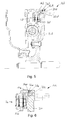
- FIG. 5 shows the torque transmission devices 1, 1a, 1c in illustration and training similar torque transmission device 1d with a disc member 5d cast.
- axial projection 14d is on the outer periphery 15d of the steel ring 31 d melted.
- the groove connection 32 d is provided.
- the axial projection 14 d is centered radially on the steel ring 31 d radially outside and fixedly connected by means of the radially outwardly disposed, provided as a through-welded joint 33 d.
- FIG. 6 shows in detail the relation to the torque transmission device 1 d slightly modified torque transmission device 1e.
- the axial projection 14e of the flange part 8e of the centrifugal pendulum 7e is centered on the radial bearing surface 34e of the steel ring 31e and welded axially calibrated by means of the weld joint 33e to the disk part 5e.
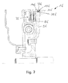
- FIG. 7 shows the opposite to the torque transmitting devices 1 d, 1 e of FIGS. 5 and 6 slightly modified torque transmission device 1f.
- this torque transmission device 1f the annular groove 35f is inserted on the outer circumference 15f.
- the wire ring 31f rolled up.
- the axial projection 14f of the flange portion 8f of the centrifugal pendulum 7f is axially and circumferentially fixedly connected. The centering of the axial projection 14f takes place on the outer circumference 15f of the disk part 5f.
Landscapes
- Engineering & Computer Science (AREA)
- General Engineering & Computer Science (AREA)
- Physics & Mathematics (AREA)
- Acoustics & Sound (AREA)
- Aviation & Aerospace Engineering (AREA)
- Mechanical Engineering (AREA)
- Mechanical Operated Clutches (AREA)
Abstract
Description
- Die Erfindung betrifft eine um eine Drehachse zwischen einer Brennkraftmaschine und einem Getriebe eines Kraftfahrzeugs angeordnete Drehmomentübertragungseinrichtung mit einem an einem Scheibenteil aufgenommenen Fliehkraftpendel enthaltend ein Flanschteil und mehreren, über den Umfang verteilt an diesem begrenzt verschwenkbar aufgenommenen Pendelmassen.
- Drehmomentübertragungseinrichtungen zwischen einer Brennkraftmaschine und einem Getriebe eines Kraftfahrzeugs dienen zum Einen der Schwingungsisolation von Drehschwingungen der Brennkraftmaschine und zum Anderen der Trennung der Brennkraftmaschine von dem Getriebe, beispielsweise eine oder im Falle eines Doppelkupplungsgetriebes zwei Reibungskupplungen. Zur Schwingungsisolation können Drehschwingungsdämpfer in Form von geteilten Schwungrädern, Torsionsschwingungsdämpfern in Kupplungsscheiben von Reibungskupplungen der Drehmomentübertragungseinrichtung für sich oder einzeln vorgesehen sein. Weiterhin können in einer Drehmomentübertragungseinrichtung separat oder in Ergänzung zu einem Drehschwingungsdämpfer drehzahladaptive Schwingungstilger in Form von Fliehkraftpendeln vorgesehen sein. Diese sind bevorzugt in eine Baugruppe der Drehmomentübertragungseinrichtung integriert. Aus der
DE 10 2011 085 865 A1 ist beispielsweise ein Fliehkraftpendel in eine Reibungskupplung integriert. Aus derDE 10 2009 052 978 A1 ist eine Drehmomentübertragungseinrichtung bekannt, bei der das Fliehkraftpendel radial innerhalb von Bogenfedern eines geteilten Schwungrads integriert ist. Eine Drehmomentübertragungseinrichtung mit einem parallel zu den Bogenfedern eines Drehschwingungsdämpfers angeordneten Fliehkraftpendel zeigt beispielsweise dieDE 10 2009 042 825 A1 . Diese Ausführungen benötigen einen hohen axialen Bauraum oder die Pendelmassen sind auf kleinem Durchmesser angeordnet, so dass die Wirkung der Pendelmassen eingeschränkt ist. Des Weiteren ist eine direkte Anbindung radial innen über Bauteile aus Blech vorgesehen, eine Anbindung an Bauteile, beispielsweise Gussteile, die nicht unmittelbar miteinander verschweißbar sind, ist nicht vorgesehen. - Aufgabe der Erfindung ist daher, eine Drehmomentübertragungseinrichtung zur Anbindung an nicht unmittelbar verschweißbare Bauteile vorzuschlagen.
- Die Aufgabe wird durch den Gegenstand des Anspruchs 1 gelöst. Die von diesem abhängigen Unteransprüche geben vorteilhafte Ausführungsformen des Gegenstands des Anspruchs 1 wieder.
- Die vorgeschlagene Drehmomentübertragungseinrichtung ist um eine Drehachse zwischen einer Brennkraftmaschine und einem Getriebe eines Kraftfahrzeugs verdrehbar angeordnet und kann im einfachsten Fall ein Fliehkraftpendel und ein dieses aufnehmendes Scheibenteil, welches beispielsweise auf einer Getriebeeingangswelle eines Getriebes verdrehbar und axial fest oder schwimmend gelagert sein kann, mit einem Ausgangsteil beispielsweise mit einer darauf montierten Kupplungsdruckplatte enthalten. Weiterhin kann in der Drehmomentübertragungseinrichtung ein Drehschwingungsdämpfer vorgesehen sein, wobei in bevorzugter Weise das Fliehkraftpendel dem Drehschwingungsdämpfer nachgeschaltet ist. Der Drehschwingungsdämpfer kann ein geteiltes Schwungrad sein. Das Fliehkraftpendel kann radial außerhalb von Energiespeichern wie beispielsweise Bogenfedern angeordnet sein und diese zumindest teilweise axial übergreifen beziehungsweise überschneiden. Das Fliehkraftpendel enthält ein am Scheibenteil aufgenommenes Flanschteil, an dem wiederum mehrere, über den Umfang verteilte und begrenzt verschwenkbare Pendelmassen aufgenommen sind. Axial gegenüberliegende Pendelmassen können mittels Ausnehmungen des Flanschteils durchgreifenden Befestigungsmitteln miteinander zu jeweils einem Pendelmassenpaar verbunden sein. Die Lagerung der Pendelmassen erfolgt bevorzugt mittels auf Laufbahnen der Pendelmasse und des Flanschteils abwälzenden Wälzkörpern wie beispielsweise Laufrollen. Das Flanschteil ist radial zumindest einen Teil der Pendelmassen übergreifend mittels eines axial erweiterten Ansatzes mit einem Außenumfangsbereich des an einem Innenumfang gelagerten Scheibenteils drehfest verbunden. Hierdurch kann das Fliehkraftpendel ohne Erweiterung nach radial innen direkt an dem Scheibenteil aufgenommen werden. Hierdurch ist direkte Zentrierung des Fliehkraftpendels an dem Scheibenteil möglich. Des Weiteren kann die Verbindung des radial außerhalb von gegebenenfalls vorhandenen Energiespeichern wie Bogenfedern eines Drehschwingungsdämpfers direkt radial außen am Scheibenteil vorgenommen werden, so dass axialer Bauraum eingespart und eine kurze und steife Verbindung zum Scheibenteil vorgeschlagen werden kann.
- Die Verbindung des Flanschteils mit dem Scheibenteil mittels des axialen Ansatzes kann unabhängig vom Material des Scheibenteils erfolgen. Beispielsweise kann das Scheibenteil aus Stahl, beispielsweise einem Schmiedeteil hergestellt sein. In besonders vorteilhafter Weise lassen sich mittels einer entsprechenden Verbindung Fliehkraftpendel mit nicht schweißbaren Materialien, beispielsweise Guss wie Grauguss oder andere Gussarten, die sich durch eine gute Wärmeleitfähigkeit insbesondere bei Verwendung des Scheibenteils als Gegendruckplatte einer Reibungskupplung auszeichnen, verbinden.
- Gemäß einer vorteilhaften Ausführungsform kann an dem aus Stahl oder Guss hergestellten Scheibenteil ein Winkelring mit dem axialen Ansatz, also einem topfförmigen, beispielsweise ausgestanzten und entsprechend umgeformten oder aus Stangenmaterial gerollten und verschweißten Blechteil angeordnet und das Flanschteil an dessen Außenumfang mit dem axialen Ansatz fest verbunden sein. Der im Querschnitt im Wesentliche rechtwinklige Winkelring wird mit seinem radialen Schenkel mit dem Außenumfangsbereich des Scheibenteils verbunden, beispielsweise mit einem aus Guss hergestellten Scheibenteil mit diesem vernietet oder bei einem aus schweißbarem Material bestehenden Scheibenteil verschweißt. Hierbei öffnet sich der axiale Ansatz von dem Scheibenteil weg. In bevorzugter Weise übergreift der axiale Ansatz die Pendelmassen auf beiden Seiten des Flanschteiles, so dass der axiale Ansatz zugleich als Berstschutz dienen kann. Der axiale Ansatz kann mit dem an sich bevorzugt ringförmig ausgebildeten Flanschteil verschweißt wie durchgeschweißt sein, wobei der axiale Ansatz das Flanschteil übergreift und einen axialen Anschlag für dieses ausbilden kann. Alternativ kann das Flanschteil in den axialen Ansatz eingepresst oder eingelegt und anschließend verstemmt werden, indem beispielsweise an der Stirnseite des axialen Ansatzes eine umlaufende Verstemmung oder über den Umfang verteilt mehrere Verstemmungsbereiche vorgesehen werden.
- Gemäß einer weiteren vorteilhaften Ausführungsform können insbesondere zur Einsparung von Bauteilen der axiale Ansatz und das Flanschteil einteilig ausgebildet sein. Hierbei wird das Fliehkraftpendel mit dem axialen Ansatz als Baugruppe hergestellt und der axiale Ansatz anschließend an dem Scheibenteil zentriert und mit diesem verbunden. Bei einem Scheibenteil aus Stahl oder Guss kann die Verbindung erfolgen, indem an dem axialen Ansatz über den Umfang verteilt angeordnete Einformbereiche vorgesehen sind. An dem Außenumfang des Scheibenteils sind hierzu komplementäre, radial nach innen erweiterte Ausnehmungen, beispielsweise Blattfedertaschen zur Befestigung von eine Anpressplatte aufnehmenden Blattfedern vorgesehen, in die bei der Verbindung von axialem Ansatz und Scheibenteil die Einformungsbereiche unter Bildung einer formschlüssigen Verbindung zumindest partiell eingeformt werden. Alternativ kann das Scheibenteil am Außenumfang über den Umfang verteilte Öffnungen, beispielsweise Bohrungen aufweisen, an denen das den Außenumfang des Scheibenteils übergreifende Flanschteil mittels Stiften verstiftet wird.
- Zur weiteren vorteilhaften Verbindung eines aus Guss hergestellten Scheibenteils mit dem einteilig aus dem Flanschteil gebildeten oder mit diesem verbundenen axialen Ansatz kann in dem Scheibenteil ein Stahlring eingegossen sein und der axiale Ansatz mit dem Stahlring verschweißt sein. Hierbei kann der eingegossene Stahlring an der dem Fliehkraftpendel zugewandten Seite eine Kontaktfläche zu dem axialen Ansatz ausbilden, so dass Ansatz und Stahlring miteinander mittels einer diese verbindenden Standard-Schweißnaht umlaufend oder über den Umfang verteilte Schweißbereiche oder-punkte verschweißt werden können. Alternativ kann der Stahlring radial außen am Scheibenteil vorgesehen sein und durch den axialen Ansatz geschweißt werden. In einer weiteren Ausführungsform kann in eine Ringnut am Außenumfang des Scheibenteils ein Stahldraht einrolliert werden und der axiale Ansatz mit diesem mittels Durchschweißen verbunden werden.
- Die Erfindung wird anhand der in den
Figuren 1 bis 7 dargestellten Ausführungsformen einer Drehmomentübertragungseinrichtung näher erläutert. Dabei zeigen: - Figur 1
- den oberen Teil einer um eine Drehachse verlagerbaren Drehmomentübertragungseinrichtung im Schnitt,
- Figur 2
- ein gegenüber der Drehmomentübertragungseinrichtung der
Figur 1 abgeändertes Detail, - Figur 3
- eine Drehmomentübertragungseinrichtung mit gegenüber der Drehmomentübertragungseinrichtung der
Figur 1 geänderten Verbindung zwischen Fliehkraftpendel und Scheibenteil, - Figur 4
- ein gegenüber der Drehmomentübertragungseinrichtung der
Figur 3 abgeändertes Detail, - Figur 5
- eine Drehmomentübertragungseinrichtung mit gegenüber den Drehmomentübertragungseinrichtungen der
Figuren 1 und3 geänderten Verbindung zwischen Fliehkraftpendel und Scheibenteil, - Figur 6
- ein gegenüber der Drehmomentübertragungseinrichtung der
Figur 5 abgeändertes Detail - und Figur 7
- eine Drehmomentübertragungseinrichtung mit gegenüber den Drehmomentübertragungseinrichtungen der
Figuren 1 ,3 und5 geänderten Verbindung zwischen Fliehkraftpendel und Scheibenteil. - Die
Figur 1 zeigt die obere Hälfte der um die Drehachse d verdrehbaren Drehmomentübertragungseinrichtung 1 im Schnitt. Die Drehmomentübertragungseinrichtung 1 enthält das beispielsweise mit einem eine Primärschwungmasse bildenden Schwungrad oder dergleichen verbindbare, in dieser Ausführungsform axial zu den Energiespeichern 3 beabstandete Eingangsteil 2 und das als Ausgangsteil 4 ausgebildete, aus Guss hergestellte und eine Sekundärschwungmasse bildende Scheibenteil 5. Das Scheibenteil 5 ist mittels einer nicht dargestellten Lagerung auf der Getriebeeingangswelle 20 eines Getriebes verdrehbar und gegebenenfalls axial fest gelagert, beispielsweise wälz- oder gleitgelagert. Eingangsteil 2 und Ausgangsteil 4 bilden mit den in Umfangsrichtung wirkenden Energiespeichern 3 den Drehschwingungsdämpfer 6. Radial außerhalb und diese zumindest teilweise axial überlappend ist das Fliehkraftpendel 7 angeordnet. Das Fliehkraftpendel 7 ist aus dem Flanschteil 8 gebildet, an dem paarweise axial gegenüberliegende Pendelmassen 9 zu Pendelmassenpaaren begrenzt verschwenkbar angeordnet sind. Die Pendelmassen 9 beziehungsweise die aus diesen gebildeten Pendelmassenpaare sind mittels Wälzkörpern 10, die auf den an Ausschnitten vorgesehenen Laufbahnen 11, 12 des Flanschteils 8 beziehungsweise der Pendelmassen 9 abwälzen, gegenüber dem Flanschteil 8 verschwenkbar aufgenommen. Die Pendelmassen 9 weisen zum Flanschteil 8 Abstandshalter 13 auf. Das Flanschteil 9 weist in dem gezeigten Ausführungsbeispiel den einteilig angeformten axialen Ansatz 14 auf, der auf dem Außenumfang 15 des Scheibenteils 5 zentriert und mit diesem fest verbunden ist. Hierzu sind am Außenumfang 15 des Scheibenteils 5 über den Umfang verteilt radial nach innen gerichtete Öffnungen 16 wie Bohrungen vorgesehen, in die die Stifte 17 eingebracht sind, die den axialen Ansatz 14 durchgreifen und diesen radial außen am Scheibenteil 5 gegen Verdrehung und axiale Verlagerung fixieren. - Die
Figur 2 zeigt im Detail die der Drehmomentübertragungseinrichtung 1 derFigur 1 ansonsten ähnliche Drehmomentübertragungseinrichtung 1a mit dem Fliehkraftpendel 7a mit einer zu der Befestigung des axialen Ansatzes 14 auf dem Scheibenteil 5 derFigur 1 abweichenden Lösung. Hier weist der axiale Ansatz 14a des Flanschteils 8a Einformungen 18a auf, die in gestrichelt angedeutete radiale und über den Umfang verteilte Ausnehmungen 19a, beispielsweise Ausschnitte im Bereich von Blattfedertaschen eingeformt sind, so dass nach radialer Zentrierung eine Verdrehsicherung und mittels der Anprägungen 21 a eine axiale Festigkeit gegenüber dem Scheibenteil 5a erzielt wird. - Die
Figur 3 zeigt die in Darstellung und Ausbildung der Drehmomentübertragungseinrichtung 1 derFigur 1 ähnliche Drehmomentübertragungseinrichtung 1 b. Im Unterschied zu dieser sind der axiale Ansatz 14b und das Flanschteil 8b des Fliehkraftpendels 7b zweiteilig ausgebildet. Hierbei ist das Scheibenteil 5b bereits vorab mit dem Winkelring 22b mittels dessen radialem Schenkel 23b zentriert und fest verbunden, hier mittels der Niete 24b. Die Niete 24b können auf demselben Lochkreis wie die Stifte 25b zur Aufnahme einer Kupplungsdruckplatte vorgesehen sein und sich mit diesen über den Umfang abwechseln. Das Flanschteil 8b ist an den axialen Anschlag 26b und radial außen zentriert an dem axialen Ansatz 14b angelegt und mittels der Schweißverbindung 27b, die an der Schweißstelle 28b mit verminderter Materialstärke als Durchschweißung ausgebildet ist, befestigt. - Die
Figur 4 zeigt im Detail die ansonsten der Drehmomentübertragungseinrichtung 1 b derFigur 3 entsprechende Drehmomentübertragungseinrichtung 1 c mit einer gegenüber der Befestigung des Fliehkraftpendels 7b an dem Scheibenteil 5b abgeänderten Lösung. Hierbei ist der Winkelring 22c mit dem axialen Ansatz 14c vorgesehen, an dessen Anschlag 26c das Flanschteil 8c des Fliehkraftpendels 7c axial angelegt und radial außen zentriert aufgenommen ist. Die Verdrehsicherung und axiale Festigkeit des Flanschteils 8c gegenüber dem Winkelring 22c und damit gegenüber dem nicht dargestellten Scheibenteil erfolgt mittels der Verstemmung 29c, die umlaufend oder aus über den Umfang verteilten Verstemmungsbereichen gebildet sein kann. - Die
Figur 5 zeigt die den Drehmomentübertragungseinrichtungen 1, 1a, 1c in Darstellung und Ausbildung ähnliche Drehmomentübertragungseinrichtung 1d mit einem Scheibenteil 5d aus Guss. Zur stoffschlüssigen Anbindung des mit dem Flanschteil 8d des Fliehkraftpendels 7d einteiligen axialen Ansatzes 14d ist an dem Außenumfang 15d der Stahlring 31 d eingeschmolzen. Zur besseren axialen Belastbarkeit der Verbindung zwischen Stahlring 31 d und Scheibenteil 5d ist die Nutverbindung 32d vorgesehen. Der axiale Ansatz 14d ist auf dem Stahlring 31 d radial außen zentriert und mittels der radial außen angeordneten, als Durchschweißung vorgesehenen Schweißverbindung 33d fest verbunden. -
Figur 6 zeigt im Detail die gegenüber der Drehmomentübertragungseinrichtung 1 d leicht abgeänderte Drehmomentübertragungseinrichtung 1e. In dieser Drehmomentübertragungseinrichtung 1 e ist das Scheibenteil 5e mit dem axial seitlich aufgeschmolzenen und mittels der Schwalbenschwanzverbindung 32e formschlüssig mit dem Scheibenteil 5e verbundenen Stahlring 31 e. Der axiale Ansatz 14e des Flanschteils 8e des Fliehkraftpendels 7e ist an der radialen Anlagefläche 34e des Stahlrings 31 e zentriert und mittels der Schweißverbindung 33e axial kalibriert mit dem Scheibenteil 5e verschweißt. - Die
Figur 7 zeigt die gegenüber den Drehmomentübertragungseinrichtungen 1 d, 1 e derFiguren 5 und 6 leicht abgeänderte Drehmomentübertragungseinrichtung 1f. In dieser Drehmomentübertragungseinrichtung 1f ist am Außenumfang 15f die Ringnut 35f eingebracht. In diese ist der Drahtring 31f eingerollt. Mit dem Drahtring 31f ist mittels der der Schweißverbindung 33d derFigur 5 ähnlichen, als Durchschweißung ausgebildeten Schweißverbindung 33f der axiale Ansatz 14f des Flanschteils 8f des Fliehkraftpendels 7f axial und in Umfangsrichtung fest verbunden. Die Zentrierung des axialen Ansatzes 14f erfolgt auf dem Außenumfang 15f des Scheibenteils 5f. -
- 1
- Drehmomentübertragungseinrichtung
- 1a
- Drehmomentübertragungseinrichtung
- 1b
- Drehmomentübertragungseinrichtung
- 1c
- Drehmomentübertragungseinrichtung
- 1d
- Drehmomentübertragungseinrichtung
- 1e
- Drehmomentübertragungseinrichtung
- 1f
- Drehmomentübertragungseinrichtung
- 2
- Eingangsteil
- 3
- Energiespeicher
- 4
- Ausgangsteil
- 5
- Scheibenteil
- 5a
- Scheibenteil
- 5b
- Scheibenteil
- 5d
- Scheibenteil
- 5e
- Scheibenteil
- 5f
- Scheibenteil
- 6
- Drehschwingungsdämpfer
- 7
- Fliehkraftpendel
- 7a
- Fliehkraftpendel
- 7b
- Fliehkraftpendel
- 7c
- Fliehkraftpendel
- 7d
- Fliehkraftpendel
- 7e
- Fliehkraftpendel
- 7f
- Fliehkraftpendel
- 8
- Flanschteil
- 8a
- Flanschteil
- 8b
- Flanschteil
- 8c
- Flanschteil
- 8d
- Flanschteil
- 8e
- Flanschteil
- 8f
- Flanschteil
- 9
- Pendelmasse
- 10
- Wälzkörper
- 11
- Laufbahn
- 12
- Laufbahn
- 13
- Abstandshalter
- 14
- axialer Ansatz
- 14a
- axialer Ansatz
- 14b
- axialer Ansatz
- 14c
- axialer Ansatz
- 14d
- axialer Ansatz
- 14e
- axialer Ansatz
- 14f
- axialer Ansatz
- 15
- Außenumfang
- 15d
- Außenumfang
- 15f
- Außenumfang
- 16
- Öffnung
- 17
- Stift
- 18a
- Einformung
- 19a
- Ausnehmung
- 20
- Getriebeeingangswelle
- 21a
- Anprägung
- 22b
- Winkelring
- 22c
- Winkelring
- 23b
- radialer Schenkel
- 24b
- Niet
- 25b
- Stift
- 26b
- Anschlag
- 26c
- Anschlag
- 27b
- Schweißverbindung
- 28b
- Schweißstelle
- 29c
- Verstemmung
- 31d
- Stahlring
- 31e
- Stahlring
- 31f
- Drahtring
- 32d
- Nutverbindung
- 32e
- Schwalbenschwanzverbindung
- 33d
- Schweißverbindung
- 33e
- Schweißverbindung
- 33f
- Schweißverbindung
- 34e
- Anlagefläche
- 35f
- Ringnut
- d
- Drehachse
Claims (10)
- Drehmomentübertragungseinrichtung (1, 1a, 1b, 1c, 1d, 1e, 1f) angeordnet um eine Drehachse (d) zwischen einer Brennkraftmaschine und einem Getriebe eines Kraftfahrzeugs mit einem an einem Scheibenteil (5, 5a, 5b, 5d, 5e, 5f) aufgenommenen Fliehkraftpendel (7, 7a, 7b, 7c, 7d, 7e, 7f) enthaltend ein Flanschteil (8, 8a, 8b, 8c, 8d, 8e, 8f) und mehrere, über den Umfang verteilt und gegenüber diesem begrenzt verschwenkbar aufgenommene Pendelmassen (9), dadurch gekennzeichnet, dass das Flanschteil (8, 8a, 8b, 8c, 8d, 8e, 8f) radial zumindest einen Teil der Pendelmassen (9) übergreifend mittels eines axial erweiterten Ansatzes (14, 14a, 14b, 14c, 14d, 14e, 14f) mit einem Außenumfangsbereich des an einem Innenumfang gelagerten Scheibenteils (5, 5a, 5b, 5d, 5e, 5f) drehfest verbunden ist.
- Drehmomentübertragungseinrichtung (1, 1 a, 1b, 1 c, 1d, 1 e, 1f) nach Anspruch 1, dadurch gekennzeichnet, dass das Scheibenteil (5, 5a, 5b, 5d, 5e, 5f) aus Guss gebildet ist.
- Drehmomentübertragungseinrichtung (1b, 1c) nach einem der Ansprüche 1 oder 2, dadurch gekennzeichnet, dass an dem Scheibenteil (5b) ein Winkelring (22b, 22c) mit dem axialen Ansatz (14b, 14c) angeordnet und das Flanschteil (8b, 8c) an dessen Außenumfang mit dem axialen Ansatz (14b, 14c) fest verbunden ist.
- Drehmomentübertragungseinrichtung (1, 1a, 1d, 1e, 1f) nach Anspruch 1 oder 2, dadurch gekennzeichnet, dass der axiale Ansatz (14, 14a, 14d, 14e, 14f) und das Flanschteil (8, 8a, 8d, 8e, 8f) einteilig ausgebildet sind.
- Drehmomentübertragungseinrichtung (1a) nach Anspruch 4, dadurch gekennzeichnet, dass der axiale Ansatz (14a) über den Umfang verteilt angeordnete Einformungen (18a) aufweist, die in radial nach innen am Außenumfang des Scheibenteils (5a) vorgesehene Ausnehmungen (19a) eingeformt sind.
- Drehmomentübertragungseinrichtung (1) nach Anspruch 4, dadurch gekennzeichnet, dass der axiale Ansatz (14) mit dem Außenumfang (15) des Scheibenteils (5) verstiftet ist.
- Drehmomentübertragungseinrichtung (1 d, 1 e) nach Anspruch 2, dadurch gekennzeichnet, dass in dem Scheibenteil (5d, 5e) ein Stahlring (31 d, 31 e) eingegossen ist und der axiale Ansatz (14d, 14e) mit dem Stahlring (31 d, 31 e) verschweißt ist.
- Drehmomentübertragungseinrichtung (1f) nach Anspruch 2, dadurch gekennzeichnet, dass in den Außenumfang (15f) des Scheibenteils (5f) ein Drahtring (31 f) einrolliert und der axiale Ansatz (14f) mit dem Drahtring (31f) verschweißt ist.
- Drehmomentübertragungseinrichtung (1, 1 a, 1b, 1 c, 1 d, 1e, 1f) nach einem der Ansprüche 1 bis 8, dadurch gekennzeichnet, dass das Fliehkraftpendel (7, 7a, 7b, 7c, 7d, 7e, 7f) radial außerhalb von Energiespeichern (3) eines Drehschwingungsdämpfers (6) und diesen zumindest teilweise axial übergreifend angeordnet ist.
- Drehmomentübertragungseinrichtung (1, 1 a, 1b, 1 c, 1 d, 1e, 1f) nach einem der Ansprüche 1 bis 9, dadurch gekennzeichnet, dass das Scheibenteil (5, 5a, 5b, 5d, 5e, 5f) auf einer Getriebeeingangswelle (20) verdrehbar gelagert ist.
Applications Claiming Priority (1)
| Application Number | Priority Date | Filing Date | Title |
|---|---|---|---|
| DE102013204748 | 2013-03-19 |
Publications (2)
| Publication Number | Publication Date |
|---|---|
| EP2781290A1 true EP2781290A1 (de) | 2014-09-24 |
| EP2781290B1 EP2781290B1 (de) | 2019-03-13 |
Family
ID=50280294
Family Applications (1)
| Application Number | Title | Priority Date | Filing Date |
|---|---|---|---|
| EP14160419.9A Revoked EP2781290B1 (de) | 2013-03-19 | 2014-03-18 | Drehmomentübertragungseinrichtung mit Fliehkraftpendel |
Country Status (2)
| Country | Link |
|---|---|
| EP (1) | EP2781290B1 (de) |
| DE (1) | DE102014204957A1 (de) |
Cited By (3)
| Publication number | Priority date | Publication date | Assignee | Title |
|---|---|---|---|---|
| CN106382331A (zh) * | 2015-07-24 | 2017-02-08 | 法雷奥离合器公司 | 用于机动车辆的传动组件 |
| CN106468327A (zh) * | 2015-08-20 | 2017-03-01 | 舍弗勒技术股份两合公司 | 离心力摆和具有离心力摆的液力变矩器 |
| CN106468326A (zh) * | 2015-08-20 | 2017-03-01 | 舍弗勒技术股份两合公司 | 离心力摆和具有离心力摆的液力变矩器 |
Families Citing this family (1)
| Publication number | Priority date | Publication date | Assignee | Title |
|---|---|---|---|---|
| DE102021107695B4 (de) | 2021-03-26 | 2024-08-14 | Schaeffler Technologies AG & Co. KG | Drehmomentübertragungsvorrichtung für einen Antriebsstrang eines Kraftfahrzeugs |
Citations (7)
| Publication number | Priority date | Publication date | Assignee | Title |
|---|---|---|---|---|
| GB2279724A (en) * | 1990-05-31 | 1995-01-11 | Luk Lamellen & Kupplungsbau | Torque transmitting apparatus |
| DE10005547A1 (de) * | 2000-02-09 | 2001-08-16 | Mannesmann Sachs Ag | Schwingungsdämpfungseinrichtung |
| EP1746305A2 (de) * | 2005-07-21 | 2007-01-24 | Renault | Schwungrad mit biegsamen Blechwerkstoff und Herstellverfahren |
| DE102009042825A1 (de) | 2008-10-30 | 2010-05-12 | Luk Lamellen Und Kupplungsbau Beteiligungs Kg | Drehmomentübertragungseinrichtung |
| DE102009052978A1 (de) | 2008-12-03 | 2010-06-17 | Luk Lamellen Und Kupplungsbau Beteiligungs Kg | Drehmomentübertragungseinrichtung |
| DE102011105009A1 (de) * | 2010-06-29 | 2011-12-29 | Schaeffler Technologies Gmbh & Co. Kg | Zweimassenschwungrad |
| DE102011085865A1 (de) | 2010-12-23 | 2012-07-19 | Schaeffler Technologies Gmbh & Co. Kg | Reibungskupplung mit Fliehkraftpendel |
Family Cites Families (1)
| Publication number | Priority date | Publication date | Assignee | Title |
|---|---|---|---|---|
| DE102009050353A1 (de) | 2008-11-19 | 2010-05-20 | Luk Lamellen Und Kupplungsbau Beteiligungs Kg | Drehschwingungsdämpfer mit separater Trägerscheibe für Pendelmassen |
-
2014
- 2014-03-18 EP EP14160419.9A patent/EP2781290B1/de not_active Revoked
- 2014-03-18 DE DE102014204957.1A patent/DE102014204957A1/de not_active Ceased
Patent Citations (7)
| Publication number | Priority date | Publication date | Assignee | Title |
|---|---|---|---|---|
| GB2279724A (en) * | 1990-05-31 | 1995-01-11 | Luk Lamellen & Kupplungsbau | Torque transmitting apparatus |
| DE10005547A1 (de) * | 2000-02-09 | 2001-08-16 | Mannesmann Sachs Ag | Schwingungsdämpfungseinrichtung |
| EP1746305A2 (de) * | 2005-07-21 | 2007-01-24 | Renault | Schwungrad mit biegsamen Blechwerkstoff und Herstellverfahren |
| DE102009042825A1 (de) | 2008-10-30 | 2010-05-12 | Luk Lamellen Und Kupplungsbau Beteiligungs Kg | Drehmomentübertragungseinrichtung |
| DE102009052978A1 (de) | 2008-12-03 | 2010-06-17 | Luk Lamellen Und Kupplungsbau Beteiligungs Kg | Drehmomentübertragungseinrichtung |
| DE102011105009A1 (de) * | 2010-06-29 | 2011-12-29 | Schaeffler Technologies Gmbh & Co. Kg | Zweimassenschwungrad |
| DE102011085865A1 (de) | 2010-12-23 | 2012-07-19 | Schaeffler Technologies Gmbh & Co. Kg | Reibungskupplung mit Fliehkraftpendel |
Cited By (3)
| Publication number | Priority date | Publication date | Assignee | Title |
|---|---|---|---|---|
| CN106382331A (zh) * | 2015-07-24 | 2017-02-08 | 法雷奥离合器公司 | 用于机动车辆的传动组件 |
| CN106468327A (zh) * | 2015-08-20 | 2017-03-01 | 舍弗勒技术股份两合公司 | 离心力摆和具有离心力摆的液力变矩器 |
| CN106468326A (zh) * | 2015-08-20 | 2017-03-01 | 舍弗勒技术股份两合公司 | 离心力摆和具有离心力摆的液力变矩器 |
Also Published As
| Publication number | Publication date |
|---|---|
| DE102014204957A1 (de) | 2014-09-25 |
| EP2781290B1 (de) | 2019-03-13 |
Similar Documents
| Publication | Publication Date | Title |
|---|---|---|
| DE102012212970A1 (de) | Drehmomentübertragungseinrichtung und Antriebsstrang mit Drehmomentübertragungseinrichtung | |
| EP3060828A1 (de) | Drehschwingungsisolationseinrichtung | |
| DE102014206738A1 (de) | Zweimassenschwungrad | |
| EP2781290B1 (de) | Drehmomentübertragungseinrichtung mit Fliehkraftpendel | |
| WO2015090308A1 (de) | Drehschwingungsdämpfer mit fliehkraftpendel | |
| DE102015210011A1 (de) | Einmassenschwungrad mit Fliehkraftpendel | |
| DE102009039997A1 (de) | Drehschwingungsdämpfer | |
| DE102019110130A1 (de) | Drehschwingungsdämpfer | |
| DE102016218386A1 (de) | Schwingungsisolationseinrichtung | |
| DE102016223192A1 (de) | Fliehkraftpendeleinrichtung | |
| DE102015218636A1 (de) | Drehschwingungsdämpfer | |
| DE102017114453A1 (de) | Drehschwingungsisolationseinrichtung mit Fliehkraftpendel | |
| DE102019110979A1 (de) | Drehschwingungsdämpfer | |
| DE102014215272A1 (de) | Zweimassenschwungrad | |
| DE102014204016A1 (de) | Zweimassenschwungrad mit Gleitlagerung und Verfahren zu dessen Montage | |
| EP2904289B1 (de) | Drehschwingungsdämpfer | |
| DE102012212817A1 (de) | Zweimassenschwungrad | |
| DE102010053256A1 (de) | Drehschwingungsdämpfer | |
| DE102009041467A1 (de) | Drehschwingungsdämpfer | |
| WO2016141941A1 (de) | Drehschwingungsdämpfer | |
| WO2015161851A1 (de) | Fliehkraftpendel | |
| DE102019128052A1 (de) | Drehschwingungsdämpfer | |
| DE102014208982A1 (de) | Schwungrad mit Fliehkraftpendel | |
| DE102011082494B4 (de) | Schwungmassenvorrichtung | |
| DE102016223362A1 (de) | Schwungradanordnung mit Fliehkraftpendel |
Legal Events
| Date | Code | Title | Description |
|---|---|---|---|
| PUAI | Public reference made under article 153(3) epc to a published international application that has entered the european phase |
Free format text: ORIGINAL CODE: 0009012 |
|
| 17P | Request for examination filed |
Effective date: 20140318 |
|
| AK | Designated contracting states |
Kind code of ref document: A1 Designated state(s): AL AT BE BG CH CY CZ DE DK EE ES FI FR GB GR HR HU IE IS IT LI LT LU LV MC MK MT NL NO PL PT RO RS SE SI SK SM TR |
|
| AX | Request for extension of the european patent |
Extension state: BA ME |
|
| RAP1 | Party data changed (applicant data changed or rights of an application transferred) |
Owner name: SCHAEFFLER TECHNOLOGIES AG & CO. KG |
|
| R17P | Request for examination filed (corrected) |
Effective date: 20150324 |
|
| RBV | Designated contracting states (corrected) |
Designated state(s): AL AT BE BG CH CY CZ DE DK EE ES FI FR GB GR HR HU IE IS IT LI LT LU LV MC MK MT NL NO PL PT RO RS SE SI SK SM TR |
|
| 17Q | First examination report despatched |
Effective date: 20160622 |
|
| STAA | Information on the status of an ep patent application or granted ep patent |
Free format text: STATUS: EXAMINATION IS IN PROGRESS |
|
| REG | Reference to a national code |
Ref country code: DE Ref legal event code: R079 Ref document number: 502014011077 Country of ref document: DE Free format text: PREVIOUS MAIN CLASS: B23K0009020000 Ipc: F16F0015140000 |
|
| RIC1 | Information provided on ipc code assigned before grant |
Ipc: F16F 15/14 20060101AFI20180808BHEP Ipc: F16F 15/131 20060101ALI20180808BHEP |
|
| GRAP | Despatch of communication of intention to grant a patent |
Free format text: ORIGINAL CODE: EPIDOSNIGR1 |
|
| STAA | Information on the status of an ep patent application or granted ep patent |
Free format text: STATUS: GRANT OF PATENT IS INTENDED |
|
| INTG | Intention to grant announced |
Effective date: 20181002 |
|
| GRAS | Grant fee paid |
Free format text: ORIGINAL CODE: EPIDOSNIGR3 |
|
| GRAA | (expected) grant |
Free format text: ORIGINAL CODE: 0009210 |
|
| STAA | Information on the status of an ep patent application or granted ep patent |
Free format text: STATUS: THE PATENT HAS BEEN GRANTED |
|
| AK | Designated contracting states |
Kind code of ref document: B1 Designated state(s): AL AT BE BG CH CY CZ DE DK EE ES FI FR GB GR HR HU IE IS IT LI LT LU LV MC MK MT NL NO PL PT RO RS SE SI SK SM TR |
|
| REG | Reference to a national code |
Ref country code: GB Ref legal event code: FG4D Free format text: NOT ENGLISH |
|
| REG | Reference to a national code |
Ref country code: CH Ref legal event code: EP Ref country code: AT Ref legal event code: REF Ref document number: 1108129 Country of ref document: AT Kind code of ref document: T Effective date: 20190315 |
|
| REG | Reference to a national code |
Ref country code: IE Ref legal event code: FG4D Free format text: LANGUAGE OF EP DOCUMENT: GERMAN |
|
| REG | Reference to a national code |
Ref country code: DE Ref legal event code: R096 Ref document number: 502014011077 Country of ref document: DE |
|
| REG | Reference to a national code |
Ref country code: NL Ref legal event code: MP Effective date: 20190313 |
|
| REG | Reference to a national code |
Ref country code: LT Ref legal event code: MG4D |
|
| PG25 | Lapsed in a contracting state [announced via postgrant information from national office to epo] |
Ref country code: NO Free format text: LAPSE BECAUSE OF FAILURE TO SUBMIT A TRANSLATION OF THE DESCRIPTION OR TO PAY THE FEE WITHIN THE PRESCRIBED TIME-LIMIT Effective date: 20190613 Ref country code: SE Free format text: LAPSE BECAUSE OF FAILURE TO SUBMIT A TRANSLATION OF THE DESCRIPTION OR TO PAY THE FEE WITHIN THE PRESCRIBED TIME-LIMIT Effective date: 20190313 Ref country code: FI Free format text: LAPSE BECAUSE OF FAILURE TO SUBMIT A TRANSLATION OF THE DESCRIPTION OR TO PAY THE FEE WITHIN THE PRESCRIBED TIME-LIMIT Effective date: 20190313 Ref country code: LT Free format text: LAPSE BECAUSE OF FAILURE TO SUBMIT A TRANSLATION OF THE DESCRIPTION OR TO PAY THE FEE WITHIN THE PRESCRIBED TIME-LIMIT Effective date: 20190313 |
|
| PG25 | Lapsed in a contracting state [announced via postgrant information from national office to epo] |
Ref country code: LV Free format text: LAPSE BECAUSE OF FAILURE TO SUBMIT A TRANSLATION OF THE DESCRIPTION OR TO PAY THE FEE WITHIN THE PRESCRIBED TIME-LIMIT Effective date: 20190313 Ref country code: NL Free format text: LAPSE BECAUSE OF FAILURE TO SUBMIT A TRANSLATION OF THE DESCRIPTION OR TO PAY THE FEE WITHIN THE PRESCRIBED TIME-LIMIT Effective date: 20190313 Ref country code: HR Free format text: LAPSE BECAUSE OF FAILURE TO SUBMIT A TRANSLATION OF THE DESCRIPTION OR TO PAY THE FEE WITHIN THE PRESCRIBED TIME-LIMIT Effective date: 20190313 Ref country code: GR Free format text: LAPSE BECAUSE OF FAILURE TO SUBMIT A TRANSLATION OF THE DESCRIPTION OR TO PAY THE FEE WITHIN THE PRESCRIBED TIME-LIMIT Effective date: 20190614 Ref country code: RS Free format text: LAPSE BECAUSE OF FAILURE TO SUBMIT A TRANSLATION OF THE DESCRIPTION OR TO PAY THE FEE WITHIN THE PRESCRIBED TIME-LIMIT Effective date: 20190313 Ref country code: BG Free format text: LAPSE BECAUSE OF FAILURE TO SUBMIT A TRANSLATION OF THE DESCRIPTION OR TO PAY THE FEE WITHIN THE PRESCRIBED TIME-LIMIT Effective date: 20190613 |
|
| PG25 | Lapsed in a contracting state [announced via postgrant information from national office to epo] |
Ref country code: ES Free format text: LAPSE BECAUSE OF FAILURE TO SUBMIT A TRANSLATION OF THE DESCRIPTION OR TO PAY THE FEE WITHIN THE PRESCRIBED TIME-LIMIT Effective date: 20190313 Ref country code: CZ Free format text: LAPSE BECAUSE OF FAILURE TO SUBMIT A TRANSLATION OF THE DESCRIPTION OR TO PAY THE FEE WITHIN THE PRESCRIBED TIME-LIMIT Effective date: 20190313 Ref country code: EE Free format text: LAPSE BECAUSE OF FAILURE TO SUBMIT A TRANSLATION OF THE DESCRIPTION OR TO PAY THE FEE WITHIN THE PRESCRIBED TIME-LIMIT Effective date: 20190313 Ref country code: RO Free format text: LAPSE BECAUSE OF FAILURE TO SUBMIT A TRANSLATION OF THE DESCRIPTION OR TO PAY THE FEE WITHIN THE PRESCRIBED TIME-LIMIT Effective date: 20190313 Ref country code: SK Free format text: LAPSE BECAUSE OF FAILURE TO SUBMIT A TRANSLATION OF THE DESCRIPTION OR TO PAY THE FEE WITHIN THE PRESCRIBED TIME-LIMIT Effective date: 20190313 Ref country code: IT Free format text: LAPSE BECAUSE OF FAILURE TO SUBMIT A TRANSLATION OF THE DESCRIPTION OR TO PAY THE FEE WITHIN THE PRESCRIBED TIME-LIMIT Effective date: 20190313 Ref country code: AL Free format text: LAPSE BECAUSE OF FAILURE TO SUBMIT A TRANSLATION OF THE DESCRIPTION OR TO PAY THE FEE WITHIN THE PRESCRIBED TIME-LIMIT Effective date: 20190313 Ref country code: PT Free format text: LAPSE BECAUSE OF FAILURE TO SUBMIT A TRANSLATION OF THE DESCRIPTION OR TO PAY THE FEE WITHIN THE PRESCRIBED TIME-LIMIT Effective date: 20190713 |
|
| REG | Reference to a national code |
Ref country code: CH Ref legal event code: PL |
|
| PG25 | Lapsed in a contracting state [announced via postgrant information from national office to epo] |
Ref country code: SM Free format text: LAPSE BECAUSE OF FAILURE TO SUBMIT A TRANSLATION OF THE DESCRIPTION OR TO PAY THE FEE WITHIN THE PRESCRIBED TIME-LIMIT Effective date: 20190313 Ref country code: LU Free format text: LAPSE BECAUSE OF NON-PAYMENT OF DUE FEES Effective date: 20190318 Ref country code: PL Free format text: LAPSE BECAUSE OF FAILURE TO SUBMIT A TRANSLATION OF THE DESCRIPTION OR TO PAY THE FEE WITHIN THE PRESCRIBED TIME-LIMIT Effective date: 20190313 |
|
| REG | Reference to a national code |
Ref country code: BE Ref legal event code: MM Effective date: 20190331 |
|
| REG | Reference to a national code |
Ref country code: DE Ref legal event code: R026 Ref document number: 502014011077 Country of ref document: DE |
|
| PLBI | Opposition filed |
Free format text: ORIGINAL CODE: 0009260 |
|
| PG25 | Lapsed in a contracting state [announced via postgrant information from national office to epo] |
Ref country code: IS Free format text: LAPSE BECAUSE OF FAILURE TO SUBMIT A TRANSLATION OF THE DESCRIPTION OR TO PAY THE FEE WITHIN THE PRESCRIBED TIME-LIMIT Effective date: 20190713 |
|
| PLAX | Notice of opposition and request to file observation + time limit sent |
Free format text: ORIGINAL CODE: EPIDOSNOBS2 |
|
| 26 | Opposition filed |
Opponent name: VALEO EMBRAYAGES Effective date: 20191213 |
|
| PG25 | Lapsed in a contracting state [announced via postgrant information from national office to epo] |
Ref country code: MC Free format text: LAPSE BECAUSE OF FAILURE TO SUBMIT A TRANSLATION OF THE DESCRIPTION OR TO PAY THE FEE WITHIN THE PRESCRIBED TIME-LIMIT Effective date: 20190313 Ref country code: CH Free format text: LAPSE BECAUSE OF NON-PAYMENT OF DUE FEES Effective date: 20190331 Ref country code: IE Free format text: LAPSE BECAUSE OF NON-PAYMENT OF DUE FEES Effective date: 20190318 Ref country code: LI Free format text: LAPSE BECAUSE OF NON-PAYMENT OF DUE FEES Effective date: 20190331 Ref country code: DK Free format text: LAPSE BECAUSE OF FAILURE TO SUBMIT A TRANSLATION OF THE DESCRIPTION OR TO PAY THE FEE WITHIN THE PRESCRIBED TIME-LIMIT Effective date: 20190313 |
|
| GBPC | Gb: european patent ceased through non-payment of renewal fee |
Effective date: 20190613 |
|
| PG25 | Lapsed in a contracting state [announced via postgrant information from national office to epo] |
Ref country code: BE Free format text: LAPSE BECAUSE OF NON-PAYMENT OF DUE FEES Effective date: 20190331 Ref country code: SI Free format text: LAPSE BECAUSE OF FAILURE TO SUBMIT A TRANSLATION OF THE DESCRIPTION OR TO PAY THE FEE WITHIN THE PRESCRIBED TIME-LIMIT Effective date: 20190313 |
|
| PG25 | Lapsed in a contracting state [announced via postgrant information from national office to epo] |
Ref country code: TR Free format text: LAPSE BECAUSE OF FAILURE TO SUBMIT A TRANSLATION OF THE DESCRIPTION OR TO PAY THE FEE WITHIN THE PRESCRIBED TIME-LIMIT Effective date: 20190313 |
|
| PG25 | Lapsed in a contracting state [announced via postgrant information from national office to epo] |
Ref country code: GB Free format text: LAPSE BECAUSE OF NON-PAYMENT OF DUE FEES Effective date: 20190613 |
|
| PLAF | Information modified related to communication of a notice of opposition and request to file observations + time limit |
Free format text: ORIGINAL CODE: EPIDOSCOBS2 |
|
| PG25 | Lapsed in a contracting state [announced via postgrant information from national office to epo] |
Ref country code: MT Free format text: LAPSE BECAUSE OF FAILURE TO SUBMIT A TRANSLATION OF THE DESCRIPTION OR TO PAY THE FEE WITHIN THE PRESCRIBED TIME-LIMIT Effective date: 20190313 |
|
| REG | Reference to a national code |
Ref country code: AT Ref legal event code: MM01 Ref document number: 1108129 Country of ref document: AT Kind code of ref document: T Effective date: 20190318 |
|
| PLBB | Reply of patent proprietor to notice(s) of opposition received |
Free format text: ORIGINAL CODE: EPIDOSNOBS3 |
|
| PG25 | Lapsed in a contracting state [announced via postgrant information from national office to epo] |
Ref country code: AT Free format text: LAPSE BECAUSE OF NON-PAYMENT OF DUE FEES Effective date: 20190318 |
|
| PG25 | Lapsed in a contracting state [announced via postgrant information from national office to epo] |
Ref country code: CY Free format text: LAPSE BECAUSE OF FAILURE TO SUBMIT A TRANSLATION OF THE DESCRIPTION OR TO PAY THE FEE WITHIN THE PRESCRIBED TIME-LIMIT Effective date: 20190313 |
|
| PG25 | Lapsed in a contracting state [announced via postgrant information from national office to epo] |
Ref country code: HU Free format text: LAPSE BECAUSE OF FAILURE TO SUBMIT A TRANSLATION OF THE DESCRIPTION OR TO PAY THE FEE WITHIN THE PRESCRIBED TIME-LIMIT; INVALID AB INITIO Effective date: 20140318 |
|
| PLAB | Opposition data, opponent's data or that of the opponent's representative modified |
Free format text: ORIGINAL CODE: 0009299OPPO |
|
| R26 | Opposition filed (corrected) |
Opponent name: VALEO EMBRAYAGES Effective date: 20191213 |
|
| APAH | Appeal reference modified |
Free format text: ORIGINAL CODE: EPIDOSCREFNO |
|
| APBM | Appeal reference recorded |
Free format text: ORIGINAL CODE: EPIDOSNREFNO |
|
| APBP | Date of receipt of notice of appeal recorded |
Free format text: ORIGINAL CODE: EPIDOSNNOA2O |
|
| APBM | Appeal reference recorded |
Free format text: ORIGINAL CODE: EPIDOSNREFNO |
|
| APBP | Date of receipt of notice of appeal recorded |
Free format text: ORIGINAL CODE: EPIDOSNNOA2O |
|
| APBQ | Date of receipt of statement of grounds of appeal recorded |
Free format text: ORIGINAL CODE: EPIDOSNNOA3O |
|
| PG25 | Lapsed in a contracting state [announced via postgrant information from national office to epo] |
Ref country code: MK Free format text: LAPSE BECAUSE OF FAILURE TO SUBMIT A TRANSLATION OF THE DESCRIPTION OR TO PAY THE FEE WITHIN THE PRESCRIBED TIME-LIMIT Effective date: 20190313 |
|
| P01 | Opt-out of the competence of the unified patent court (upc) registered |
Effective date: 20230525 |
|
| PGFP | Annual fee paid to national office [announced via postgrant information from national office to epo] |
Ref country code: FR Payment date: 20240328 Year of fee payment: 11 |
|
| PGFP | Annual fee paid to national office [announced via postgrant information from national office to epo] |
Ref country code: DE Payment date: 20240521 Year of fee payment: 11 |
|
| REG | Reference to a national code |
Ref country code: DE Ref legal event code: R103 Ref document number: 502014011077 Country of ref document: DE Ref country code: DE Ref legal event code: R064 Ref document number: 502014011077 Country of ref document: DE |
|
| APBU | Appeal procedure closed |
Free format text: ORIGINAL CODE: EPIDOSNNOA9O |
|
| RAP4 | Party data changed (patent owner data changed or rights of a patent transferred) |
Owner name: SCHAEFFLER TECHNOLOGIES AG & CO. KG |
|
| RDAF | Communication despatched that patent is revoked |
Free format text: ORIGINAL CODE: EPIDOSNREV1 |
|
| STAA | Information on the status of an ep patent application or granted ep patent |
Free format text: STATUS: PATENT REVOKED |
|
| RDAG | Patent revoked |
Free format text: ORIGINAL CODE: 0009271 |
|
| REG | Reference to a national code |
Ref country code: CH Ref legal event code: PL |
|
| 27W | Patent revoked |
Effective date: 20241115 |
|
| REG | Reference to a national code |
Ref country code: AT Ref legal event code: MA03 Ref document number: 1108129 Country of ref document: AT Kind code of ref document: T Effective date: 20241115 |