EP2780529B1 - Ventilation device for the profiled frame of a leaf, and air exchange method at a window - Google Patents
Ventilation device for the profiled frame of a leaf, and air exchange method at a window Download PDFInfo
- Publication number
- EP2780529B1 EP2780529B1 EP12812368.4A EP12812368A EP2780529B1 EP 2780529 B1 EP2780529 B1 EP 2780529B1 EP 12812368 A EP12812368 A EP 12812368A EP 2780529 B1 EP2780529 B1 EP 2780529B1
- Authority
- EP
- European Patent Office
- Prior art keywords
- ventilation device
- housing
- flow
- opening
- window
- Prior art date
- Legal status (The legal status is an assumption and is not a legal conclusion. Google has not performed a legal analysis and makes no representation as to the accuracy of the status listed.)
- Not-in-force
Links
Images

Classifications
-
- E—FIXED CONSTRUCTIONS
- E06—DOORS, WINDOWS, SHUTTERS, OR ROLLER BLINDS IN GENERAL; LADDERS
- E06B—FIXED OR MOVABLE CLOSURES FOR OPENINGS IN BUILDINGS, VEHICLES, FENCES OR LIKE ENCLOSURES IN GENERAL, e.g. DOORS, WINDOWS, BLINDS, GATES
- E06B7/00—Special arrangements or measures in connection with doors or windows
- E06B7/02—Special arrangements or measures in connection with doors or windows for providing ventilation, e.g. through double windows; Arrangement of ventilation roses
- E06B7/10—Special arrangements or measures in connection with doors or windows for providing ventilation, e.g. through double windows; Arrangement of ventilation roses by special construction of the frame members
-
- E—FIXED CONSTRUCTIONS
- E06—DOORS, WINDOWS, SHUTTERS, OR ROLLER BLINDS IN GENERAL; LADDERS
- E06B—FIXED OR MOVABLE CLOSURES FOR OPENINGS IN BUILDINGS, VEHICLES, FENCES OR LIKE ENCLOSURES IN GENERAL, e.g. DOORS, WINDOWS, BLINDS, GATES
- E06B7/00—Special arrangements or measures in connection with doors or windows
- E06B7/02—Special arrangements or measures in connection with doors or windows for providing ventilation, e.g. through double windows; Arrangement of ventilation roses
- E06B2007/023—Air flow induced by fan
Definitions
- the invention relates to a window ventilation device, which is able to exchange air between an exterior space and an interior, while the quality of the air in the interior "to improve".
- the window ventilation device is not more than area-wise installation in the profiled frame allows and there are elements of the fixed (immovable) frame used as hollow chambers in the form of flow channels for the air duct for heat and / or moisture exchange.
- the EP 1 486 637 discloses a ventilation device for a window, in which two opening areas are provided on opposite sides of a housing, in order to allow outside air to flow inwards and inside air to the outside. In a central region, a heat exchanger is provided.
- WO 2011/105 969 is a ventilation device with a heat exchanger known. Fans can circulate airflow from inside to outside and from outside to inside.
- a problem of the claimed invention is to realize the covert installation of such a window ventilation device on site. It is not intended to be fully integrated into the fixed frame, but must protrude in areas (in terms of volume). Despite the window ventilation device in the fixed frame (frame), the glass size in the movable wing is to remain, so the frame should not be larger (expand inward) to accommodate the ventilation unit, but the glass portion of the wing should remain the same size. Additionally created installation spaces, which are at the expense of the door or window glass size of the movable sash, are to be avoided according to the task.
- a "movement” is understood to mean tilting, swiveling or pushing, or any combination thereof.
- the claimed window ventilation device requires four openings (understood in the general sense also "outlets”, which also include an inlet, just abstract in the sense of a “flow opening” as the opening area).
- Two flow openings are to be provided to the outside (not: directed), with a view of the wing as parting plane, "outside” in the sense of the weather-dependent side.
- Two flow openings are to be placed on the inside ("inside” overlooking the living area).
- the window ventilation device is easy to maintain, which is required for replacement of filters or heat exchanger elements or electronic components from time to time.
- the window ventilation device is also suitable for being placed in a center post (in the sense of a broadening profile).
- the out-of-frame cantilever is not too big.
- the term of the window is also to be seen as a French door or door as such.
- the term of the window is functional to look at, so provided with a glass insert, which should not be reduced according to task and at the same time to achieve ventilation on his profile frame (fixed frame).
- Sensors can be provided. Two sensors can be used in conjunction with the electrical circuit on the board to detect the installation position of the ventilation unit, as a "device" mounted on the right or left of the profile frame (frame) without having to define the right or left device in the production. Thus, only one device type, which automatically adjusts to the right or left during installation, can be manufactured.
- Temperature sensors for an antifreeze strategy may also be present to protect the ventilation unit from icing during operation.
- the antifreeze strategy for avoiding icing of the ventilation unit by control measures is as follows.
- a temperature sensor in the exhaust air duct (the channel that leads the air to the outside) is arranged.
- the ventilation unit is mounted on the right or left of the fixed frame (frame)
- two temperature sensors one in each example outermost flow channel attached be.
- an installer adjusts the unit to a left or right ventilation unit, and the control system selects the correct sensor as the "outgoing sensor" (FO outward sensor).
- the electronic / electrical control operates with a hysteresis of a few ° C, for example between 2 ° C to 4 ° C.
- the electronic control on the board in response to a fan speed (speed) down the supply fan (fan for the air CLOSED), in particular completely off.
- the supply air fan is again at the same stage (at the same speed) as the exhaust fan (the fan of the exhaust air AB, which is the exhaust air FO after the heat exchanger).
- the ventilation unit can be of symmetrical design and it is not known before final assembly how it is installed, there may be a possibility that the unit tunes the volume flows to the respective mode (right / left). The installer therefore adjusts when installing the housing, whether it is a right or left installation.
- the on-board electronics can regulate the fans so that the top fan is operated as an exhaust fan and the bottom fan as a supply fan.
- the supply air fan is set to a slightly lower speed, so that it is ensured that there is no supply air surplus in the interior (outlet from CLOSED).
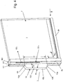
- FIG. 4 is particularly clear that only a small portion of the window ventilation device actually engages with its housing 10 in the profile frame 8v, or even only touching a surface portion (facing left) is applied.
- the opening portions 12, 13, 14 and 15 of the end face 10d facing the vertical profile spar 8v FIG. 1 take over the air duct (air intake or air outlet).
- the compact size of the ventilation device 1 which has an extent of a1 'as a projection, a width a3 and a height a2, can be seen.
- the housing 10 When removed, the housing 10 has a transverse dimension of a1.
- the dimensions a1, a2, a3 define the volume of the ventilation device 1, wherein two rounded edges 10a and 10b are defined by wall sections which at the same time delimit flow paths on the inside of the housing 10, as at the intersection of the FIG. 2 is apparent.
- the window ventilation device 1 with its housing 10 and the two flow paths S1 and S2 will be explained in more detail with the other figures.
- the rear wall 10c (on the left side), which adjoins the two curved walls 10a and 10b, is the most projecting piece or patch of the window ventilation apparatus. This can be accommodated by a wall recess provided on site, without the vertical frame section 8v itself having to be widened to accommodate the ventilation device. Window area 7 is not lost.
- the fixed frame 8 as a profile frame 8v (vertical section) and 8h (horizontal section) remains immovable. Hence his naming as a fixed frame.
- the ventilation device 1 according to FIG. 1 and FIG. 2 is adapted to be just a little way into this frame profile 8 (vertical 8v, horizontal 8h) inserted or just attached to it sealingly. Accordingly, the opening portions 12 to 15 are each surrounded by a seal, or surrounded by a respective recessed groove in a circumferential groove, which is an air-tight seal with a view or relative to the vertical portion 8v allow the fixed frame 8 (vertical profile spar 8v or air-bearing intermediate component).
- the piece a1 " is shown, which the device 1 can be sunk with its front narrow side 10d in the frame profile section 8v, when it is not mounted on-the-rest.
- the housing 10 with its wall sections which define both the housing and define the illustrated flow paths S1 and S2 in the interior of the housing are designated by 10a, 10b, 10c and on the flat side by 10e and 10f.
- the two flow paths S1 and S2 intersect.
- the air guided by them is, however, not touchingly crossed, but guided by using a heat exchanger insert 30 flowing past each other, but not touching.
- the heat exchanger 30 is inserted as an insert element in the crossing region 9, and the guide lines S1 and S2 show how the air flows functionally, from inside to outside, or from outside to inside.
- the flow paths in the area 9 can also be passed not crossing each other, which is also evident from the web guide only the outer flow path and only the inner flow path, the axial fans used 20, 21 are then placed differently, one in every flow path.
- An adapted heat exchanger element 30 '(not shown separately) is then to be used.
- the flow itself is made possible by the two axial fans 20, 21, which are placed at the two inner opening regions 12, 14, like that FIG. 2 and 3 is apparent.
- the axial fan 20 operates the flow path S2.
- the axial fan 21 operates the flow path S1.
- the axial fans are respectively arranged at the inlet of the flow path, ie S2a and S1a (a for beginning).
- An additional filter 22 or 23 is arranged on the respective fan 20, 21.
- the other two opening areas which are also spaced from the two already spaced opening portions 12, 14 and do not overlap with them, are the outflow openings 13 and 15. They are the end of the respective flow path S1 and S2, the flow path S1, operated from the axial fan 21, led over the crossing region 9 leads to the outlet S1e. If the exhaust air AB is placed at S1a, the exhaust air FO results at S1e.
- the other flow S2 designed from the other axial fan 20.
- the flow path starts at S2a, passes over the crossing area 9 and ends at the more remote, outside opening area 15 with the outlet S2e (e for end). If the fan 20, for example, associated with the sucked outside air AU, he leads the sucked outside air through the crossing region 9 and the heat exchanger element 30, where this air is conditioned, the output S2e for the blown into the room supply air ZU.
- the further opening 11 is closed by a cover 40, the trough-like 43 is formed and is designed rectangular in the example.
- the cover 40 has a trough 43 which is suitable for receiving a board P, which is equipped with electrical and electronic components.
- a cover 41 may be provided, which closes the open space 43, in which the board is inserted.
- Corresponding web guides for electrical lines are in FIG. 3 can be seen, leading even with the cover 41 closed in the interior 43 and the fan 20,21-controlled by the electronics - supply power.
- the axial fans 20,21 can be controlled, are controlled in their speed or in the form of an on / off operation.
- the board P can take over other technological functions of the window ventilation device 1, so control of avoidance of supply air excess, temperature control, temperature monitoring (frost / icing protection of the heat exchanger), signaling, maintenance conditions, maintenance intervals and location detections by attaching appropriate sensors to the elongated housing 10 in the flow paths, preferably at their ends, are placed so that the device automatically recognizes in which mounting position it is installed to define inlet / outlet, which are assigned to the four opening areas 12 to 15. These vary depending on the installation position, and accordingly, the circuit and its sensors can respond to the installation position to be detected and the window ventilation device 1 functionally set accordingly, namely automated.
- the front side 10d ('front' narrow side) is the functional side, the other sides are more passive sides. All flows end and start at the front, the heat exchanger 30 is used here, removed and replaced.
- the board is placed here, replaced, repaired or reused, and also the filter plates 22,23 for the fans are placed here and / or replaced or maintained.
- the entire maintenance of the window ventilation device is done from the (narrow) end face 10d.
- the entire function also takes place from this narrow side (front side).
- the heat exchanger insert 30 can be formed hexagonal, with two surface areas take over the placement in the receiving trough 10c 'and the cover used 40, and two inclined surface portions form the connection to the respective end of a respective curved guide wall, so that the two inclined end portions of the heat exchanger of the left or right side of FIG. 2 each defining two inlet / outlet areas through which the flow of air is carried out.
- the heat exchanger thus defines a closed region in the crossing region 9, which is crossed by two flow paths, wherein the heat exchanger 30 itself is formed of a plurality of superimposed plates, so that there is an alternating layering of the air flowing through and thus a countercurrent heat exchanger with high Efficiency can be used.
- the heat exchanger insert 30 is completely received by the housing 10. It connects to the in-house flow paths into which it can be inserted. Likewise, the heat exchanger can be removed for maintenance purposes, or completely replaced if damaged or end of its life cycle. In the same way, the axial fans 21,20 are exchangeable, or the filter plates 22,23, which may be provided with a network to filter out coarse suspended matter.
- FIG. 2 shows the two axial fans at the two further inner opening portions 12,14. This is a possible embodiment, which can also be inverted, so that the two outer opening regions 13, 15 carry the two axial fans 20, 21. A corresponding web guide of the respective flow path S1 and S2 is then realized by correspondingly shaped wall sections within the housing 10.
- crossing area 9 is not mandatory, as in the FIG. 2 shown.
- heat exchangers can be used as insert elements, which realize a parallel guidance (no crossing of the flow paths S1 / S2).
- axial fans are placed both axial fans on the side further to the left or to place both axial fans on the side further to the right so that the two opening regions 12, 13 each receive an axial fan or in another embodiment the two Opening areas 14,15 each wear an axial fan.
- the web guides of the flow paths S1 'and S2' are then to be selected accordingly.
- the appropriate choice of the shape of the opening areas is a rectangle. This is favorable at least for those opening areas 12, 14 that are provided with an axial fan.
- the other, more in the design of free to choose opening areas 15,13 are designed for reasons of ergonomics in the example also quadrangular. However, other forms are also possible, for example, rounded shapes.
- functional opening area (s) is present that allows a flow outlet or flow inlet for the air to be supplied.
- the wall of the housing 10 is made thin, not more than with a material thickness of 2 to 5 mm thickness. Only on mounting areas For example, stronger sections may occur, such as in section 48, 49, which defines connection flanges to be mounted with sleeves 48a, 49a on the vertical frame section 8v. The stronger portions 49/48 are provided on the upper and lower walls 10g and 10h.
- each of the opening areas is bounded by the front side with a wall thickness of the housing.
- This wall thickness of the housing 12a, 13a, 14a, 15a may be provided with a groove which receives an inserted seal.
- the sealing contact edge is thus the seal. It is located on a surface of the hollow profile or on a surface of another connection component, which is designed for the further air flow.
- the housing wall can also engage or abut directly on or a little way into the vertical section 8v of the profile frame.
- the "sealing contact edge" for the surface area of this frame profile serves to continue the respective flow path from the flow paths S1 and S2 of the housing 10 into or from the hollow chambers H1, H2, H3 of the frame profile.
- the fans are designed so that they fit into the associated opening portions 12,14 and can be recorded there, optionally with the addition of a circumferential (elastomeric ) Frame gasket (not shown in FIG. 3 , but mutatis mutandis apparent as 20a and 21a in FIG. 2 ).
- a circumferential (elastomeric ) Frame gasket not shown in FIG. 3 , but mutatis mutandis apparent as 20a and 21a in FIG. 2 .
- the filter plate (or filter disc) covering it to the outside which are placed in front of the axial fans and not protrude from the end face 10d, but is also completely absorbed by the respective opening area.
- the outer surface of the vertical hollow profile 8v is a flat surface, all the end edges 13a, 12a, 14a and 15a of the four opening regions end in a functional mounting plane M which defines a seating of the housing 10 on the outer surface of the hollow profile.
- the sizing for a compact ventilation device 1, determined by the outer dimension of the housing 10, can be described for the various areas of application.
- Compact means that the device in its greatest extent of the housing 10 is not longer than 700 mm, preferably less than 550 mm has the greatest extent extent. This is the first, biggest measure. This size is smaller than the distance of locking pin, or the maximum screw spacing of the profiled fixed frame. The device should fit longitudinally into its functional environment so that it would not require any modification of a normal assembly in any case, and in the worst case would not force it.
- Compact is the housing 10 (and thus also the ventilation unit 1) also because it is adapted and suitable for profile depths of the fixed frame of less than 100 mm, preferably less than 80 mm.
- the compact ventilation device 1 has a width dimension a3 (in the direction of the tread depth) of less than 80 mm. This is the smallest, third measure.
- the housing 10 and thus the ventilation device 1 should be adjustable and installable.
- a piece of the second dimension absolutely between 5 mm and 20 mm and relative to a1 between 5% and 25%, can be inserted in the profile frame and reduces the projecting length a1 'to less than 100 mm.
- the embodiments meet the environmental conditions in that the housing is inserted a maximum of a little way into the profile of the fixed frame (frame), if not even the frontal plane 10d is placed directly to the mounting plane M on the outer surface of the vertical wing profile 8v.
- a transverse extent of the housing 10, perpendicular to the plane of said narrow side 10d is in the sense of a compact construction also less than 80 mm.
- the housing 10 does not require it so that a complete breakthrough of the entire on-site wall is necessary to place the ventilation unit between the room inside and the room outside along the entire wall depth, but a relatively small to be designated space is sufficient, from the inside of the room goes out, but the outside is not reached.
- a "depth extension" of the housing 10 is therefore preferably less than 80 mm.
- Most frame profiles 8 have a greater depth and bridge the space between the inner surface and the outer surface of the wall in the window or door area.
- Compact devices have dimensions that are less than 12 cm x 70 cm x 10 cm, in particular less than 12 cm x 55 cm x 8 cm.
- the entire depth in the extension direction of the face
Landscapes
- Engineering & Computer Science (AREA)
- Civil Engineering (AREA)
- Structural Engineering (AREA)
- Specific Sealing Or Ventilating Devices For Doors And Windows (AREA)
- Ventilation (AREA)
- Air-Flow Control Members (AREA)
- Cooling Or The Like Of Electrical Apparatus (AREA)
Description
Die Erfindung betrifft ein Fenster-Lüftungsgerät, welches in der Lage ist, Luft zwischen einem Außenraum und einem Innenraum auszutauschen und dabei die Luft im Innenraum qualitativ "zu verbessern". Dem Fenster-Lüftungsgerät wird ein nicht mehr als bereichsweiser Einbau in den profilierten Rahmen ermöglicht und es werden Elemente des fest stehenden (unbeweglichen) Rahmens als Hohlkammern in Form von Strömungskanälen für die Luftführung zum Wärme- und/oder Feuchtigkeitstausch verwendet.The invention relates to a window ventilation device, which is able to exchange air between an exterior space and an interior, while the quality of the air in the interior "to improve". The window ventilation device is not more than area-wise installation in the profiled frame allows and there are elements of the fixed (immovable) frame used as hollow chambers in the form of flow channels for the air duct for heat and / or moisture exchange.
Aus der
Die
In der
Eine Problemstellung der beanspruchten Erfindung liegt darin, den verdeckten Einbau eines solchen Fenster-Lüftungsgeräts bauseits zu realisieren. Es soll dabei nicht vollständig in den Festrahmen integriert sein, sondern muss bereichsweise (volumenmäßig betrachtet) herausragen. Trotz des Fenster-Lüftungsgeräts im Festrahmen (Blendrahmen) soll die Glasgröße im beweglichen Flügel erhalten bleiben, der Blendrahmen soll also nicht größer werden (sich nach innen ausweiten), um das Lüftungsgerät aufzunehmen, sondern der Glasanteil des Flügels soll gleich groß bleiben. Zusätzlich geschaffene Bauräume, die auf Kosten der Tür- oder Fensterglasgröße des beweglichen Flügels gehen, sind aufgabengemäß zu vermeiden. Unter einer "Bewegung" wird ein Kippen, Schwenken oder Schieben verstanden, auch deren beliebige Kombination.A problem of the claimed invention is to realize the covert installation of such a window ventilation device on site. It is not intended to be fully integrated into the fixed frame, but must protrude in areas (in terms of volume). Despite the window ventilation device in the fixed frame (frame), the glass size in the movable wing is to remain, so the frame should not be larger (expand inward) to accommodate the ventilation unit, but the glass portion of the wing should remain the same size. Additionally created installation spaces, which are at the expense of the door or window glass size of the movable sash, are to be avoided according to the task. A "movement" is understood to mean tilting, swiveling or pushing, or any combination thereof.
Die Lösung findet sich in Anspruch 1 oder Anspruch 15.The solution can be found in
Gegenstand der Beanspruchung ist nur das Fenster-Lüftungsgerät und seine Eigenschaften oder Eignungen, in einen feststehenden Rahmen (Blendrahmen) eines Flügels (mit einem Flügelrahmen und einem Glaselement) eingebaut zu werden, ohne dass damit der Rahmen oder das Rahmenprofil als solches oder der Flügel oder das Glaselement mit beansprucht ist. Soweit dieser Profilrahmen in Form von Funktions- und Eignungsangaben genannt ist (als Zweckbestimmung oder Zweckverwirklichung), dient das Hohlprofil zur komplementären Umschreibung der Anpassung, Ausgestaltung und Eignung des Fenster- Lüftungsgeräts als solches (und seines Arbeitsverfahrens).Subject of the claim is only the window ventilation unit and its properties or aptitudes, in a fixed frame (frame) of a wing (with a sash and a glass element) to be installed without affecting the frame or the frame profile as such or the wing or the glass element is claimed with. As far as this profile frame is mentioned in the form of functional and suitability specifications (as a purpose or purpose realization), the hollow profile is used to complement the adaptation, design and suitability of the window ventilation device as such (and its working method).
Vom Wesen her benötigt das beanspruchte Fenster-Lüftungsgerät dabei vier Öffnungen (im allgemeinen Sinne verstanden auch "Auslässe", wobei diese auch einen Einlass umfassen, eben abstrakt im Sinne einer "Strömungsöffnung" als Öffnungsbereich).In essence, the claimed window ventilation device requires four openings (understood in the general sense also "outlets", which also include an inlet, just abstract in the sense of a "flow opening" as the opening area).
Zwei Strömungsöffnungen sind nach außen wirkend (nicht: gerichtet) bereitzustellen, mit Blick auf den Flügel als Trennebene, "außen" im Sinne der wetterabhängigen Seite. Zwei Strömungsöffnungen sind für die Innenseite wirkend zu platzieren ("innen" mit Blick auf den Wohnbereich). Diese vier Strömungs-Öffnungsbereiche, zwei davon sind Auslässe, zwei davon sind Ansaugöffnungen, sind so passend auf das Lüftungsgerät verteilt, dass sie strömungstechnisch günstig liegen, das Fenster-Lüftungsgerät bautechnisch klein gestalten lassen und gleichzeitig Umgebungsbedingungen erfüllen, die den Einbau des Blendrahmens aus Hohlprofilen in der Bauausnehmung erreichen.Two flow openings are to be provided to the outside (not: directed), with a view of the wing as parting plane, "outside" in the sense of the weather-dependent side. Two flow openings are to be placed on the inside ("inside" overlooking the living area). These four flow-opening areas, two of which are outlets, two of which are suction, are distributed to the ventilation unit so that they are favorable flow, let the window ventilation device small in construction and at the same time meet environmental conditions, the installation of the frame of hollow sections reach in the Bauausnehmung.
Erfindungsgemäß ist das Fenster-Lüftungsgerät einfach zu warten, was zum Auswechseln von Filtern oder Wärmetauscher-Elementen oder Elektronikbauteilen von Zeit zu Zeit erforderlich ist.According to the invention, the window ventilation device is easy to maintain, which is required for replacement of filters or heat exchanger elements or electronic components from time to time.
Erfindungsgemäß ist das Fenster-Lüftungsgerät auch geeignet, in einem Mittelpfosten (im Sinne eines Verbreiterungsprofils) platziert zu werden. Die außerhalb des Rahmens gelegene Auskragung ist dabei nicht zu groß.According to the invention, the window ventilation device is also suitable for being placed in a center post (in the sense of a broadening profile). The out-of-frame cantilever is not too big.
Die Strömungen und ihre Richtungen sind für außen und innen im Sprachgebrauch (in Deutschland) normiert. Angesaugte Außenluft (AU) tritt ein und wird im Lüftungsgerät konditioniert. Die Konditionierung durch Erwärmung erfolgt durch die aus dem Innenraum abgesaugte "alte" Innenluft, die beim Ansaugen Abluft heißt (AB). Die am Ende dieses Weges nach außen abgegebene Fortluft (FO) ergibt sich. Auf der Innenseite heißen die beiden Strömungsrichtungen Abluft (AB) für die aus dem Raum vom Fenster-Lüftungsgerät angesaugte "schlechte" Luft, dagegen ist die in den Raum eingeblasene Zuluft (ZU), die angesaugte Außenluft (AU), konditioniert und erwärmt als neue Raumluft, die in den Innenraum eingeblasen wird. Die Konditionierung (Erwärmung) erfolgt mit der kreuzenden oder vorbeiströmenden Abluft (AB). AB konditioniert AU für ZU und wird FO.The currents and their directions are standardized for outside and inside in the usage of language (in Germany). Sucked outside air (AU) enters and is conditioned in the ventilation unit. The conditioning by heating takes place through the "old" inside air extracted from the interior, which is called exhaust air when sucked in (AB). The exhaust air (FO) emitted to the outside at the end of this path results. On the inside, the two flow directions are called exhaust air (AB) for those out of the room from the window ventilation unit sucked "bad" air, on the other hand is the supply air blown into the room (ZU), the sucked outside air (AU), conditioned and heated as new room air, which is blown into the interior. The conditioning (heating) takes place with the exhaust air flowing through or passing by (AB). AB conditions AU for ZU and becomes FO.
Sofern in der folgenden Beschreibung unterschiedliche oder abweichende Begriffe verwendet werden, sind sie sinngemäß zu interpretieren. Angesaugte Außenluft, nach außen abgegebene Fortluft betreffen den Außenraum. Eingeblasene Innenluft und aus dem Raum abgesaugte Abluft betreffen den Innenraum. Es sind immer zumindest beide Begriffspaare zum Verständnis zu verwenden, die Richtung und der Ort (AN/AB und innen/außen). Sofern dabei die normierten Begriffe Außenluft, Fortluft, Zuluft und Abluft nicht immer harmonisiert verwendet werden, sind sie gemäß den hier gemachten Angaben sinngemäß im physikalischen Zusammenhang zu interpretieren.If different or different terms are used in the following description, they shall be interpreted analogously. Aspirated outside air, exhaust air discharged to the outside affect the outside space. Blown inside air and exhaust air extracted from the room affect the interior. At least both pairs of terms are always to be used for understanding, the direction and the place (AN / AB and inside / outside). If the standardized terms outside air, exhaust air, supply air and exhaust air are not always used in a harmonized manner, they must be interpreted in the physical context in accordance with the information given here.
Soweit von einem Fenster-Lüftungsgerät gesprochen wird, ist der Begriff des Fensters auch als Fenstertür oder Tür als solche zu sehen. Der Begriff des Fensters ist funktionell zu betrachten, also mit einem Glas-Einsatz versehen, der gemäß Aufgabe nicht verkleinert werden soll und gleichzeitig Lüftungsmöglichkeit an seinem Profilrahmen (Festrahmen) erreichen soll.As far as a window ventilation device is spoken, the term of the window is also to be seen as a French door or door as such. The term of the window is functional to look at, so provided with a glass insert, which should not be reduced according to task and at the same time to achieve ventilation on his profile frame (fixed frame).
Sensoren können vorgesehen sein. Zwei Sensoren können in Verbindung mit der elektrischen Schaltung auf der Platine zur Erkennung der Einbaulage des Lüftungsgeräts, als rechts oder links am Profilrahmen (Blendrahmen) angebauten "Gerät" dienen, ohne vorher in der Fertigung das rechte oder linke Gerät definieren zu müssen. Es kann also nur eine Gerätetype, die sich beim Einbau automatisch auf rechts oder links einstellt, gefertigt werden.Sensors can be provided. Two sensors can be used in conjunction with the electrical circuit on the board to detect the installation position of the ventilation unit, as a "device" mounted on the right or left of the profile frame (frame) without having to define the right or left device in the production. Thus, only one device type, which automatically adjusts to the right or left during installation, can be manufactured.
Temperatursensoren für eine Frostschutzstrategie können auch vorhanden sein, um das Lüftungsgerät im Betrieb vor Vereisung zu schützen.Temperature sensors for an antifreeze strategy may also be present to protect the ventilation unit from icing during operation.
Die Frostschutzstrategie zur Vermeidung eines Vereisens des Lüftungsgeräts durch steuerungstechnische Maßnahmen ist wie folgt.The antifreeze strategy for avoiding icing of the ventilation unit by control measures is as follows.
Um ein Vereisen des Wärmeübertragers (Wärmetauscher-Einsatzes) zu verhindern, ist ein Temperatursensor im Fortlufttrakt (dem Kanal, der die Luft nach außen führt) angeordnet. Da vor dem endgültigen Einbau nicht bekannt ist, ob das Lüftungsgerät rechts oder links am Festrahmen (Blendrahmen) montiert wird, können zwei Temperatursensoren, einer im beispielsweise jeweils äußersten Strömungskanal angebracht sein. Bei der Endmontage stellt ein Monteur am Gerät ein, ob es sich um ein linkes oder rechtes Lüftungsgerät handelt und die Steuerung wählt dazu den richtigen Sensor als "Fortluftsensor" aus (Sensor für die nach außen abgegebene Fortluft FO).In order to prevent icing of the heat exchanger (heat exchanger insert), a temperature sensor in the exhaust air duct (the channel that leads the air to the outside) is arranged. As it is not known before the final installation, whether the ventilation unit is mounted on the right or left of the fixed frame (frame), two temperature sensors, one in each example outermost flow channel attached be. During final assembly, an installer adjusts the unit to a left or right ventilation unit, and the control system selects the correct sensor as the "outgoing sensor" (FO outward sensor).
Die elektronische/elektrische Steuerung arbeitet mit einer Hysterese von wenigen °C, beispielsweise zwischen 2°C bis 4°C.The electronic / electrical control operates with a hysteresis of a few ° C, for example between 2 ° C to 4 ° C.
Wenn die Fortlufttemperatur (die Temperatur der Fortluft FO) im Betrieb unter einen eingestellten ersten Wert von z. B. 2°C sinkt, regelt die elektronische Steuerung auf der Platine in Abhängigkeit von einer Ventilatorstufe (Drehzahl) den Zuluftventilator herunter (Ventilator für die Luft ZU), insbesondere ganz aus.When the exhaust air temperature (the temperature of the exhaust air FO) in operation below a set first value of z. B. 2 ° C drops, the electronic control on the board in response to a fan speed (speed) down the supply fan (fan for the air CLOSED), in particular completely off.
Wenn die Fortlufttemperatur wieder auf einen größeren Wert, z. B. ca. 4°C angestiegen ist, wird der Zuluftventilator wieder auf der gleichen Stufe (mit der gleichen Drehzahl) wie der Abluftventilator (der Ventilator der Abluft AB, die nach dem Wärmetauscher die Fortluft FO ist) betrieben.If the exhaust air temperature returns to a higher value, eg. B. has risen about 4 ° C, the supply air fan is again at the same stage (at the same speed) as the exhaust fan (the fan of the exhaust air AB, which is the exhaust air FO after the heat exchanger).
Strategie zur Vermeidung von Zuluftüberschuss ist in Anspruch 13 beschrieben.Strategy for avoiding excess air supply is described in
Da das Lüftungsgerät symmetrisch aufgebaut sein kann und vor der Endmontage nicht feststeht, wie es eingebaut wird, kann eine Möglichkeit gegeben sein, dass das Gerät die Volumenströme auf den jeweiligen Modus (rechts/links) abstimmt. Der Monteur stellt daher beim Einbau des Gehäuses ein, ob es sich um einen rechten oder linken Einbau handelt.Since the ventilation unit can be of symmetrical design and it is not known before final assembly how it is installed, there may be a possibility that the unit tunes the volume flows to the respective mode (right / left). The installer therefore adjusts when installing the housing, whether it is a right or left installation.
Die auf der Platine befindliche Elektronik kann die Ventilatoren damit so regeln, dass der jeweils oben liegende Ventilator als Abluftventilator und der untere als Zuluftventilator betrieben wird. Der Zuluftventilator wird auf eine etwas geringere Drehzahl eingestellt, so dass sichergestellt ist, dass kein Zuluftüberschuss im Innenraum (Auslass von ZU) entsteht.The on-board electronics can regulate the fans so that the top fan is operated as an exhaust fan and the bottom fan as a supply fan. The supply air fan is set to a slightly lower speed, so that it is ensured that there is no supply air surplus in the interior (outlet from CLOSED).
Ausführungsbeispiele der Erfindung werden im Folgenden beschrieben. Sie erleichtern und Ergänzen das Verständnis der beanspruchten Erfindung.
-
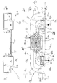
Figur 1 - ist eine Stirnansicht eines Fester-
Lüftungsgeräts 1 auf seine Stirnseite. Dieses Gerät besitzt einGehäuse 10 mit vierÖffnungen 12 bis 15, die Einlass- oder Auslass für eine Luftströmung sind. -
Figur 2 - veranschaulicht einen Schnitt A-A aus
Figur 1Gehäuses 10 und senkrecht zur Stirnseite. In dieser Schnittansicht ist der innere Aufbau der Strömungswege zu sehen, ein Strömungsweg S1 und ein zweiter Strömungsweg S2, die sich im Beispiel derFigur 2Wärmetauscher 30 platziert. -
Figur 3 - ist eine Explosionsdarstellung des Geräts der
Figur 1Gehäuse 10 nimmt diese Elemente auf und enthält Wände, die Bahnführungen definieren, unter anderem für die Strömungswege S1 und S2. - Figur 4
- ist der eingebaute Zustand eines Lüftungsgeräts 1 an einem fest stehenden
Rahmen 8, der im Ausschnitt dargestellt ist. Es sind Hohlkammern H1, H2, H3 in Längsrichtung ersichtlich, die zur Luft-Strömungsführung verwendet werden, was hier aber nicht näher erläutert wird. Sichtbar sind nur zwei laterale Strömungsöffnungen, von denen S2e die Ausströmöffnung in den Innenraum ist und die Strömungsöffnung S1a ist die Ansaugöffnung für die aus dem Innenraum zu entnehmende Abluft AB. Diese werden in entsprechenden Hohlkammern (als Kanäle) des Rahmenprofils geleitet und gelangen zu den Strömungswegen S1 und S2 des angebauten Fenster-Lüftungsgeräts 1 mit seinem Gehäuse 10 (oder stammen von diesen Strömungswegen im Gerät 1).
- FIG. 1
- is an end view of a fixed
ventilation device 1 on its front side. This device has ahousing 10 with fouropenings 12 to 15 which are inlet or outlet for air flow. - FIG. 2
- illustrates a section AA
FIG. 1 , ie in the longitudinal direction of thehousing 10 and perpendicular to the end face. In this sectional view, the inner structure of the flow paths can be seen, a flow path S1 and a second flow path S2, which in the example of theFIG. 2 cross. The crossing area is 9 and at this point aheat exchanger 30 is placed. - FIG. 3
- is an exploded view of the device
FIG. 1 , with all the components that are responsible for the function. Thehousing 10 receives these elements and includes walls that define web guides, including the flow paths S1 and S2. - FIG. 4
- is the installed state of a
ventilation device 1 on a fixedframe 8, which is shown in the cutout. There are hollow chambers H1, H2, H3 seen in the longitudinal direction, which are used for air flow guidance, which will not be explained in detail here. Only two lateral flow openings are visible, of which S2e is the outflow opening into the interior, and the flow opening S1a is the intake opening for the exhaust air AB to be taken from the interior. These are passed in corresponding hollow chambers (as channels) of the frame profile and reach the flow paths S1 and S2 of the attachedwindow ventilation device 1 with its housing 10 (or originate from these flow paths in the device 1).
Mit
Auch an
Die Maße a1, a2, a3 definieren das Volumen des Lüftungsgeräts 1, wobei zwei abgerundete Kanten 10a und 10b durch Wandabschnitte definiert werden, die gleichzeitig auf der Innenseite des Gehäuses 10 Strömungswege begrenzen, wie das am Schnitt der
Das Fenster-Lüftungsgerät 1 mit seinem Gehäuse 10 und den beiden Strömungswegen S1 und S2 soll mit den übrigen Figuren näher erläutert werden.The
Die Rückwand 10c (an der linken Seite), die sich an die beiden gebogenen Wände 10a und 10b anschließt, ist das am Weitesten herausragende Stück oder Flächenstück des Fenster-Lüftungsgeräts. Dieses kann von einer bauseits vorgesehenen Mauerausnehmung aufgenommen werden, ohne dass der vertikale Rahmenabschnitt 8v selbst verbreitert werden muss, um das Lüftungsgerät aufzunehmen. Fensterfläche 7 geht dabei nicht verloren.The
Als Orientierung soll das eingeführte Koordinatensystem x, y und z gemäß
Zu
Das Lüftungsgerät 1 gemäß
Der außerhalb des Rahmens verbleibende Abschnitt a1' des Gehäuses 10 ist in
In
Das Gehäuse 10 mit seinen Wandabschnitten, die sowohl das Gehäuse begrenzen, wie auch im Innenraum des Gehäuses die dargestellten Strömungswege S1 und S2 festlegen, sind mit 10a, 10b, 10c sowie flachseitig mit 10e und 10f benannt.The
In der Ausführung der
In einem nicht dargestellten Beispiel können die Strömungswege im Bereich 9 auch nicht kreuzend aneinander vorbeigeführt werden, was anhand der Bahnführung nur des äußeren Strömungswegs und nur des inneren Strömungswegs ebenso ersichtlich ist, wobei die verwendeten Axiallüfter 20, 21 dann anders zu platzieren sind, einer in jedem Strömungsweg. Ein angepasstes Wärmetauscher-Element 30' (nicht gesondert dargestellt) ist dann zu verwenden.In an example, not shown, the flow paths in the
Die Strömung selbst wird von den beiden Axiallüftern 20, 21 ermöglicht, die an den beiden weiter innen liegenden Öffnungsbereichen 12,14 platziert sind, wie das aus
Die weiteren beiden Öffnungsbereiche, die auch von den zwei ohnehin schon beabstandeten Öffnungsbereichen 12, 14 beabstandet sind und mit ihnen nicht überlappen, sind die Ausströmöffnungen 13 und 15. Sie sind das Ende des jeweiligen Strömungsweges S1 bzw. S2, wobei der Strömungsweg S1, bedient von dem Axiallüfter 21, über den Kreuzungsbereich 9 geführt zum Auslass S1e führt. Ist bei S1a die Abluft AB platziert, ergibt sich bei S1e die Fortluft FO.The other two opening areas, which are also spaced from the two already spaced opening
In gleicher Weise oder sagen wir "funktionell vergleichbar" ist der andere Strömungsweg S2, ausgehend von dem anderen Axiallüfter 20 gestaltet. Hier beginnt der Strömungsweg bei S2a, führt über den Kreuzungsbereich 9 und endet am entfernteren, außen liegenden Öffnungsbereich 15 mit dem Auslass S2e (e für Ende). Ist der Lüfter 20 beispielweise der angesaugten Außenluft AU zugeordnet, führt er die angesaugte Außenluft über den Kreuzungsbereich 9 und das Wärmetauscher-Element 30, wo diese Luft konditioniert wird, dem Ausgang S2e für die in den Raum eingeblasene Zuluft ZU zu.In the same way or say "functionally comparable" is the other flow S2, designed from the other
Ersichtlich ist, dass jeweils ein nahe beieinander liegendes Paar von Öffnungsbereichen 12,13 bzw. 14,15 vorgesehen ist, die aber funktionell nicht zusammengehören, sondern unterschiedlichen Strömungswegen angehören.It can be seen that in each case a pair of opening
Die Beabstandung dieser beiden Paare 12,13 und 14,15 erfolgt durch den Zwischenbereich 11, der als weiterer Öffnungsbereich für die Aufnahme des Wärmetauscher-Elements vorgesehen ist, um diesen in dem Kreuzungsbereich 9 austauschbar zu platzieren. Entsprechende Haltekanten und Aufnahmen (beispielsweise an der rückwärtigen Wand 10c als Aufnahmemulde 10c') fixieren oder halten das Wärmetauscher-Element 30 (zusätzlich).The spacing of these two
Die weitere Öffnung 11 wird verschlossen durch eine Abdeckung 40, die muldenartig 43 ausgebildet ist und im Beispiel rechteckig gestaltet ist.The
Die Abdeckung 40 hat eine Mulde 43, die zur Aufnahme einer Platine P geeignet ist, die mit elektrischen und elektronischen Bauelementen bestückt ist. Zusätzlich kann eine Abdeckung 41 vorgesehen sein, welche den offenen Raum 43 verschließt, in den die Platine eingelegt ist. Entsprechende Bahnführungen für elektrische Leitungen sind in
Mit der Platine P und ihren elektronischen/elektrischen Bauelementen, die nicht gesondert dargestellt sind, können die Axiallüfter 20,21 gesteuert werden, in ihrer Drehzahl gesteuert werden oder in Gestalt eines An/Aus-Betriebs.With the board P and its electronic / electrical components, which are not shown separately, the
Die Platine P kann weitere technologische Funktionsaufgaben des Fenster-Lüftungsgeräts 1 übernehmen, so Steuerung der Vermeidung von Zuluftüberschuss, Temperatursteuerung, Temperaturüberwachung (Frost-/Vereisungsschutz des Wärmetauschers), Signalisierung, Wartungszustände, Wartungsintervalle und Lageerkennungen, die durch Anbringung geeigneter Sensoren an dem langgestreckten Gehäuse 10 in den Strömungswegen, bevorzugt an deren Enden, so platziert sind, dass das Gerät selbsttätig erkennt, in welcher Einbaulage es eingebaut ist, um Einlass/Auslass festzulegen, die den vier Öffnungsbereichen 12 bis 15 zugewiesen sind. Diese verändern sich je nach Einbaulage, und entsprechend können die Schaltung und ihre Sensoren auf die zu erkennende Einbaulage reagieren und das Fenster-Lüftungsgerät 1 funktionell entsprechend einstellen, und zwar automatisiert.The board P can take over other technological functions of the
Die Stirnseite 10d ('vordere' Schmalseite) ist die funktionstragende Seite, die anderen Seiten sind eher passive Seiten. Alle Strömungen enden und beginnen an der Stirnseite, der Wärmetauscher 30 wird hier eingesetzt, entnommen und ausgetauscht. Die Platine wird hier platziert, ausgetauscht, repariert oder neu eingesetzt, und auch die Filterplatten 22,23 für die Lüfter werden hier platziert und/oder ausgetauscht oder gewartet.The front side 10d ('front' narrow side) is the functional side, the other sides are more passive sides. All flows end and start at the front, the
Die gesamte Wartung des Fenster-Lüftungsgeräts geschieht von der (schmalen) Stirnseite 10d aus. Die gesamte Funktion erfolgt ebenfalls von dieser Schmalseite (Stirnseite) aus.The entire maintenance of the window ventilation device is done from the (narrow) end face 10d. The entire function also takes place from this narrow side (front side).
In der genauen Ausgestaltung kann der Wärmetauscher-Einsatz 30 sechseckig ausgebildet werden, wobei zwei Flächenbereiche die Platzierung bei der Aufnahmemulde 10c' und bei der eingesetzten Abdeckung 40 übernehmen, und jeweils zwei geneigte Flächenabschnitte den Anschluss an das jeweilige Ende einer jeweils gekrümmten Führungswand bilden, so dass die zwei geneigt verlaufenden Endbereiche des Wärmetauschers der linken oder rechten Seite der
Der Wärmetauscher-Einsatz 30 wird vollständig von dem Gehäuse 10 aufgenommen. Er schließt an die gehäuseinternen Strömungswege an, in die er einschiebbar ist. Ebenso kann der Wärmetauscher aber zu Wartungszwecken herausgenommen werden, oder bei Beschädigung oder Ende seines Lebenszyklusses vollständig ausgetauscht werden. In gleicher Weise sind auch die Axiallüfter 21,20 austauschbar, oder aber die Filterplatten 22,23, die mit einem Netz versehen sein können, um grobe Schwebestoffe herauszufiltern.The
Werden zwei Strömungswege S1 und S2 verwendet, werden nicht mehr als zwei Axiallüfter 21,22 benötigt. Diese Lüfter sind bevorzugt am Einlass eines jeweiligen Strömungswegs platziert.If two flow paths S1 and S2 are used, no more than two
Die besondere Ausgestaltung der
Es war auch angesprochen worden, dass der Kreuzungsbereich 9 nicht zwingend ist, wie in der
In einer solchen modifizierten Ausgestaltung, die nicht gesondert dargestellt ist, ist ein weiteres Ausführungsbeispiel zu sehen.In such a modified embodiment, which is not shown separately, a further embodiment can be seen.
Weitere Möglichkeiten der Platzierung der Axiallüfter liegen darin, beide Axiallüfter auf der weiter links liegenden Seite zu platzieren oder beide Axiallüfter auf der weiter rechts liegenden Seite so zu platzieren, dass die beiden Öffnungsbereiche 12,13 je einen Axiallüfter erhalten oder in einer anderen Ausführung die beiden Öffnungsbereiche 14,15 je einen Axiallüfter tragen. Die Bahnführungen der Strömungswege S1' und S2' (nicht gesondert dargestellt) sind dann entsprechend zu wählen.Further possibilities for the placement of the axial fans are to place both axial fans on the side further to the left or to place both axial fans on the side further to the right so that the two opening
Alle aufgeführten Möglichkeiten der Platzierung der verschiedenen Lüfter, der Kreuzung oder der Nicht-Kreuzung sind miteinander austauschbar.All listed ways of placing the various fans, intersection or non-intersection are interchangeable.
Es versteht sich an der bildlichen Darstellung, dass die geeignete Wahl der Form der Öffnungsbereiche ein Rechteck ist. Dies ist zumindest für diejenigen Öffnungsbereiche 12,14 günstig, die mit einem Axiallüfter versehen sind. Die anderen, eher in der Gestaltung freier zu wählenden Öffnungsbereiche 15,13 sind aus Gründen der Ergonomie im Beispiel auch viereckig gestaltet. Andere Formen sind indes ebenso möglich, beispielsweise auch abgerundete Formen. Maßgebend ist allein, dass funktionelle(r) Öffnungsbereich(e) vorhanden ist/sind, der/die einen Strömungs-Auslass oder einen Strömungs-Einlass für die zu führende Luft ermöglicht.It is understood from the pictorial representation that the appropriate choice of the shape of the opening areas is a rectangle. This is favorable at least for those opening
Ebenso ersichtlich an den Beispielen ist, dass die Wand des Gehäuses 10 dünn ausgestaltet ist, nicht mehr als mit einer Materialstärke von 2 bis 5 mm Stärke. Nur an Montagebereichen können stärkere Abschnitte auftreten, wie im Bereich 48,49, der Anschlussflansche festlegt, die mit Muffen 48a,49a an dem vertikalen Rahmenabschnitt 8v zu montieren sind. Die stärkeren Bereiche 49/48 sind an der oberen und unteren Wand 10g und 10h vorgesehen.Also evident from the examples is that the wall of the
Durch die Festlegung der Gehäuse-Wandstärke wird jeder der Öffnungsbereiche von stirnseitig mit einer Wandstärke des Gehäuses begrenzt. Diese Wandstärke des Gehäuses 12a,13a, 14a,15a kann mit einer Nut versehen sein, die eine eingelegte Dichtung aufnimmt. Die dichtende Anlagekante ist damit die Dichtung. Sie liegt an einer Fläche des Hohlprofils oder an einer Fläche eines weiteren Anschlussbauteils an, welches für die weitere Luftführung ausgebildet ist.By fixing the housing wall thickness, each of the opening areas is bounded by the front side with a wall thickness of the housing. This wall thickness of the
Ist eine Dichtung nicht gesondert vorgesehen, kann die Gehäusewand auch direkt an oder ein Stück weit in den vertikalen Abschnitt 8v des Profilrahmens eingreifen oder anliegen. Die "dichtende Anlagekante" für den Flächenbereich dieses Rahmenprofils dient der Fortführung des jeweiligen Strömungswegs aus den Strömungswegen S1 und S2 des Gehäuses 10 in die oder von den Hohlkammern H1, H2, H3 des Rahmenprofils.If a seal is not provided separately, the housing wall can also engage or abut directly on or a little way into the
Für die genaue Ausführung der Axiallüfter 20,21 und der zugehörigen Filterscheiben (oder Filterplatten) versteht sich, dass die Lüfter so gestaltet sind, dass sie in die zugehörigen Öffnungsbereiche 12,14 passen und dort aufgenommen werden können, gegebenenfalls unter Hinzunahme einer umlaufenden (elastomeren) Rahmendichtung (nicht dargestellt in
Ist die Außenfläche des vertikalen Hohlprofils 8v eine ebene Fläche, enden alle Stirnkanten 13a,12a,14a und 15a der vier Öffnungsbereiche in einer funktionellen Montageebene M, die ein Aufsetzen des Gehäuses 10 auf die Außenfläche des Hohlprofils definiert.If the outer surface of the vertical
Die Größenbemessung für ein kompaktes Lüftungsgerät 1, festgelegt durch die Außenabmessung des Gehäuses 10, können für die verschiedenen Anwendungsbereiche umschrieben werden.The sizing for a
Kompakt heißt, dass das Gerät in seiner größten Erstreckung des Gehäuses 10 nicht länger als 700 mm ist, bevorzugt weniger als 550 mm als größtes Erstreckungsmaß besitzt. Dies ist das erste, größte Maß. Diese Größe ist kleiner als der Abstand von Riegelzapfen, oder aber dem maximalen Schraubabstand des profilierten Festrahmens. Das Gerät soll sich in Längsrichtung so in seine funktionelle Umgebung einfügen, dass es als kompakt benannt jedenfalls keine Modifikation einer normalen Montage erfordern würde und schlimmstenfalls auch nicht erzwingt.Compact means that the device in its greatest extent of the
Kompakt ist das Gehäuse 10 (und damit auch das Lüftungsgerät 1) auch deshalb, weil es für Profiltiefen des Festrahmens von weniger als 100 mm, bevorzugt weniger als 80 mm angepasst und geeignet ist. Bevorzugt hat das kompakte Lüftungsgerät 1 ein Breitenmaß a3 (in Richtung der Profiltiefe) von weniger als 80 mm. Dies ist das kleinste, dritte Maß.Compact is the housing 10 (and thus also the ventilation unit 1) also because it is adapted and suitable for profile depths of the fixed frame of less than 100 mm, preferably less than 80 mm. Preferably, the
Es verbleiben im eingebauten Zustand als aus dem Rahmenprofil seitlich herausragender Abschnitt a1' des Gehäuses 10 nicht mehr als 100 mm. Dies passt sogar in ein Verbreiterungsprofil eines Mittelpfostens, der jedenfalls erzwingt, dass weniger als 100 mm Bauraum nur zur Verfügung stehen. Auch hier soll das Gehäuse 10 und damit das Lüftungsgerät 1 einpassbar und einbaubar sein.It remain in the installed state as from the frame profile laterally projecting portion a1 'of the
Dies ist das mittlere, zweite Maß a1, das kleiner als a2 und größer als a3 ist. Ein Stück des zweiten Maßes, absolut zwischen 5 mm und 20 mm und relativ zu a1 zwischen 5 % und 25 % kann in den Profilrahmen eingesetzt sein und reduziert die auskragende Länge a1' auf weniger als 100 mm.This is the middle, second measure a1, which is smaller than a2 and larger than a3. A piece of the second dimension, absolutely between 5 mm and 20 mm and relative to a1 between 5% and 25%, can be inserted in the profile frame and reduces the projecting length a1 'to less than 100 mm.
Alle Maßwerte sind dabei als "praktische Maße" mit ein wenig Toleranz (zumindest ± 1 %) zu sehen.All measurements are to be seen as "practical dimensions" with a little tolerance (at least ± 1%).
Die Ausführungsformen erfüllen die Umfeld-Bedingungen dadurch, dass das Gehäuse maximal ein Stück weit in das Profil des Festrahmens (Blendrahmen) eingesetzt wird, wenn nicht sogar die Stirnebene 10d unmittelbar mit der Montageebene M auf die Außenfläche des vertikalen Flügelprofils 8v aufgesetzt wird.The embodiments meet the environmental conditions in that the housing is inserted a maximum of a little way into the profile of the fixed frame (frame), if not even the frontal plane 10d is placed directly to the mounting plane M on the outer surface of the
Eine Quererstreckung des Gehäuses 10, senkrecht zur Ebene der genannten Schmalseite 10d ist im Sinne eines kompakten Aufbaus auch weniger als 80 mm. Das Gehäuse 10 erfordert es damit nicht, dass ein vollständiger Durchbruch der gesamten bauseitigen Wand notwendig ist, um das Lüftungsgerät zwischen der Rauminnenseite und der Raumaußenseite entlang der gesamten Wandtiefe zu platzieren, vielmehr genügt ein relativ klein zu benennender Bauraum, der von der Innenseite des Raumes ausgeht, aber die Außenseite nicht erreicht.A transverse extent of the
Eine "Tiefenerstreckung" des Gehäuses 10 ist deshalb bevorzugt weniger als 80 mm. Die meisten Rahmenprofile 8 haben eine größere Tiefe und überbrücken den Raum zwischen der Innenfläche und der Außenfläche der Wand im Fenster- oder Türbereich.A "depth extension" of the
Kompakte Geräte haben Maße, die unter 12 cm x 70 cm x 10 cm liegen, insbesondere unter 12 cm x 55 cm x 8 cm. Damit das Gerät selbst hoch effektiv ist, wird die gesamte Tiefe (in Erstreckungsrichtung der Stirnseite) für die Strömungsbahnen zur Verfügung gestellt. Dies entspricht dem Maß a3 in
Claims (15)
- A window ventilation device, arranged for the installation to not more than an extent in a frame profile (8) for a wing of a window or a door, by leaving a section of the ventilation device outside of the frame profile (8), the ventilation device- having a housing (10) whose wall sections both delimit the housing and also determine at least two flow paths (S1, S2) in an interior space of the housing (10), which flow paths intersect each other within the housing (10) in an intersection region (9);characterized in that- the housing (10) comprises four spaced and/or non-overlapping opening regions (12 to 15) for the inflow or outflow of air, which opening regions are all arranged on the same narrow side (10d) of the housing (10).
- A window ventilation device according to claim 1, wherein two of the opening regions (12, 14) accommodate one axial ventilating fan (20, 21) each.
- A window ventilation device according to claim 1 or 2, wherein a further opening region (11) is provided for accommodating a heat exchanger insert (30), said further opening region (11) being arranged on the same narrow side (10d) of the housing, wherein a cover (40) is adjusted to seal the further opening region (11).
- A window ventilation device according to one of claims 1 to 3, wherein the heat exchanger insert (30) can be inserted up to the intersection region of the two intersecting flow paths (S1, S2) in the interior of the housing, or the intersection region is arranged in such a way that the exchanger insert (30) is accommodated completely.
- A window ventilation device according to claim 4, wherein the cover (40) comprises an elongated trough (43) for accommodating a circuit board (P) with an electrical circuit arranged thereon for controlling axial ventilating fans (20, 21).
- A window ventilation device according to one of claims 1 to 5, wherein two openings regions (13, 15), which are situated further to the outside as seen in the longitudinal direction of the narrow side (10d), do not carry a fan and wherein two opening regions (12, 14), which are situated further to the inside as seen in the longitudinal direction of the narrow side (10d), carry one axial ventilating fan (20, 21) each.
- A window ventilation device according to one of the preceding claims 3 to 6, wherein the further opening region (11) for accommodating a heat exchanger (30) is situated between the two outer and/or between the two opening regions situated further to the inside.
- A window ventilation device according to one of the preceding claims, wherein each of the opening regions, as seen from the front side, is delimited by a wall thickness of the housing (13a, 12a, ...) for forming a sealing contact edge for a surface area of the frame profile (8, 8v) and for continuing the respective flow path into or out of the hollow chambers of the frame profile.
- A window ventilation device according to one of the preceding claims, wherein the housing (10) is rounded off on two corner regions (10a, 10b), which rounded-off sections delimit inner flow paths and cannot be accommodated by the frame profile.
- A window ventilation device according to claim 8, whereby the front side edges (13a, ...) of the opening regions comprise grooves for accommodating sealing sheets for providing sealing contact with a surface of the frame profile (8, 8v).
- A window ventilation device according to one of the preceding claims, which(a) is not longer than 700 mm in the longitudinal direction of its longest extension (a2) of the housing, especially shorter than 550 mm; and/or(b) it is suitable for profile depths of less than 100 mm in such a way that its narrowest width (a3) is less than 100 mm, especially less than 80 mm; and/or(c) a transverse extension (a1) of the housing (10) is less than 120 mm, wherein the transverse extension extends perpendicularly to a plane of the narrow side (10d), and allows an installation (a1") over a short section in the frame profile (8v) in particular, so that the section (a1') of the housing provided or remaining outside of the frame profile (8v) is less than 100 mm.
- A window ventilation device according to one of the preceding claims 1 to 11, wherein at least one temperature sensor (52) is provided in a flow channel (S2) for enabling protection from frost or icing.
- A window ventilation device according to one of the preceding claims 2 to 12, wherein one of the axial ventilating fans (20, 21) can be operated at a lower speed for avoiding an excess of feed air (in the internal space).
- A window ventilation device according to one of claims 2 to 13, wherein a respective flat filter (22, 23) is positioned in front of the respective axial ventilating fan (20, 21).
- A method for the exchange of air from a room via a ventilation device (1) which comprises at least four flow openings (12 to 15) on a narrow side (10d), wherein- a first air flow is extracted by suction along a first path (S1) by a first axial ventilating fan (121) at a flow opening (14), said flow being guided via a heat exchanger insert (30) and being delivered to another flow opening (13);- a second air flow is extracted by suction along a second path (S2) by a second axial ventilating fan (20) at a third flow opening (12), said flow being guided via the heat exchanger insert (30) and being delivered to another further flow opening (15), andall four flow openings (12 to 15) are arranged on one and the same narrow side (10d).
Applications Claiming Priority (2)
| Application Number | Priority Date | Filing Date | Title |
|---|---|---|---|
| DE201110055522 DE102011055522B4 (en) | 2011-11-18 | 2011-11-18 | Ventilation device for the profiled frame of a wing (window ventilation unit) and air exchange method |
| PCT/IB2012/056456 WO2013072871A1 (en) | 2011-11-18 | 2012-11-15 | Ventilation device for the profiled frame of a leaf, and air exchange method at a window |
Publications (2)
| Publication Number | Publication Date |
|---|---|
| EP2780529A1 EP2780529A1 (en) | 2014-09-24 |
| EP2780529B1 true EP2780529B1 (en) | 2017-04-12 |
Family
ID=47520187
Family Applications (1)
| Application Number | Title | Priority Date | Filing Date |
|---|---|---|---|
| EP12812368.4A Not-in-force EP2780529B1 (en) | 2011-11-18 | 2012-11-15 | Ventilation device for the profiled frame of a leaf, and air exchange method at a window |
Country Status (5)
| Country | Link |
|---|---|
| EP (1) | EP2780529B1 (en) |
| CN (1) | CN104053849B (en) |
| DE (1) | DE102011055522B4 (en) |
| IN (1) | IN2014CN04385A (en) |
| WO (1) | WO2013072871A1 (en) |
Families Citing this family (3)
| Publication number | Priority date | Publication date | Assignee | Title |
|---|---|---|---|---|
| WO2016034921A1 (en) * | 2014-09-05 | 2016-03-10 | Skaala Oy | Window-fitted ventilation unit and building ventilation system |
| FI126565B (en) * | 2014-09-05 | 2017-02-15 | Skaala Production Oy | Ventilation window |
| DE102018007864A1 (en) * | 2018-10-05 | 2020-04-09 | Siegenia-Aubi Kg | Ventilation device |
Family Cites Families (8)
| Publication number | Priority date | Publication date | Assignee | Title |
|---|---|---|---|---|
| ATE59457T1 (en) * | 1985-05-28 | 1991-01-15 | Siegenia Frank Kg | VENTILATION DEVICE, ESPECIALLY FOR THE SUPPLY OF AIR IN ROOMS. |
| EP1486637B1 (en) * | 2003-06-12 | 2009-08-05 | Lidartech Co., Ltd. | Window having a ventilation equipment |
| CN2616647Y (en) * | 2003-08-21 | 2004-05-19 | 北京绿创环保科技有限责任公司 | Ventilating sound-insulating window |
| KR20080015230A (en) * | 2006-08-14 | 2008-02-19 | 노홍구 | No fan - double window system with melting blind |
| FR2924741B1 (en) * | 2007-12-07 | 2013-03-29 | Aldes Aeraulique | METHOD FOR MANUFACTURING A GLASS ELEMENT, VENTILATION MODULE AND GLASS ELEMENT EQUIPPED WITH SUCH A MODULE |
| KR20110045338A (en) * | 2009-10-26 | 2011-05-04 | (주) 에이에이치씨 시스템창 | Structure of the sliding door ChangHo which a compound valve is installed |
| SI23299A (en) * | 2010-02-23 | 2011-08-31 | Mik, D.O.O. | Ventilation device |
| DE202011003463U1 (en) | 2011-02-28 | 2011-06-01 | Schellenberg, Nico, 07745 | Window frame with integrated decentralized ventilation system with heat recovery |
-
2011
- 2011-11-18 DE DE201110055522 patent/DE102011055522B4/en not_active Expired - Fee Related
-
2012
- 2012-11-15 WO PCT/IB2012/056456 patent/WO2013072871A1/en active Application Filing
- 2012-11-15 IN IN4385CHN2014 patent/IN2014CN04385A/en unknown
- 2012-11-15 EP EP12812368.4A patent/EP2780529B1/en not_active Not-in-force
- 2012-11-15 CN CN201280067399.4A patent/CN104053849B/en not_active Expired - Fee Related
Non-Patent Citations (1)
| Title |
|---|
| None * |
Also Published As
| Publication number | Publication date |
|---|---|
| DE102011055522A1 (en) | 2013-05-23 |
| WO2013072871A1 (en) | 2013-05-23 |
| CN104053849B (en) | 2017-03-08 |
| DE102011055522B4 (en) | 2013-09-26 |
| EP2780529A1 (en) | 2014-09-24 |
| IN2014CN04385A (en) | 2015-09-04 |
| CN104053849A (en) | 2014-09-17 |
Similar Documents
| Publication | Publication Date | Title |
|---|---|---|
| DE102015121193B4 (en) | Framework for a control cabinet arrangement | |
| EP2594725B1 (en) | Window | |
| EP2850272B1 (en) | Frame ventilation device, window arrangement and installation window with a ventilation device for ventilating and for maintaining conventional glazing dimensions and also frame dimensions | |
| EP3513470B1 (en) | Electrical cabinet assembly with at least two electrical cabinets having a frame and an interior fitting component | |
| EP2487429B1 (en) | Square-shaped, particularly cuboid, casing for keeping components of a climate and/or room air control system | |
| DE102017105568A1 (en) | Modular air flap system | |
| EP2987941A1 (en) | Gate, in particular vertical lifting gate, for closing an opening in a wall separating two different temperature zones from each other | |
| EP2780529B1 (en) | Ventilation device for the profiled frame of a leaf, and air exchange method at a window | |
| DE10315753B4 (en) | Fixation of a heat exchanger cassette | |
| DE102012106253B3 (en) | When installed, replaceable ventilation unit to ventilate and maintain the regular glazing size | |
| EP2916079B1 (en) | Frame assembly for windows, doors or curtain façades with at least one heating agent | |
| EP3165701A1 (en) | Ventilation element for window with flap acting as chicane | |
| EP2369253B1 (en) | Ventilating apparatus for rooms | |
| EP3957815B1 (en) | Device for shading windows or door openings extending over a corner | |
| EP2987940A1 (en) | Gate, in particular vertical lifting gate, for closing an opening in a wall separating two different temperature zones from each other | |
| EP1715133B1 (en) | A tip-over ventilation system for windows | |
| EP2982014B1 (en) | Achieving a protection rating for electric and electronic devices, in particular switchgear cabinets | |
| DE20314559U1 (en) | Electrically powered fire damper | |
| DE102014007901A1 (en) | Cooling arrangement | |
| DE19816623C2 (en) | Bulkhead module and bulkhead built from bulkhead modules | |
| EP2375180A2 (en) | Dehumidifying device | |
| DE202016008921U1 (en) | Window insulation element | |
| EP1034351B1 (en) | Ventilating device | |
| EP4166745A1 (en) | Roller shutter/lamellar-blind box | |
| DE202011001500U1 (en) | hinge |
Legal Events
| Date | Code | Title | Description |
|---|---|---|---|
| PUAI | Public reference made under article 153(3) epc to a published international application that has entered the european phase |
Free format text: ORIGINAL CODE: 0009012 |
|
| 17P | Request for examination filed |
Effective date: 20140616 |
|
| AK | Designated contracting states |
Kind code of ref document: A1 Designated state(s): AL AT BE BG CH CY CZ DE DK EE ES FI FR GB GR HR HU IE IS IT LI LT LU LV MC MK MT NL NO PL PT RO RS SE SI SK SM TR |
|
| DAX | Request for extension of the european patent (deleted) | ||
| 17Q | First examination report despatched |
Effective date: 20160829 |
|
| GRAP | Despatch of communication of intention to grant a patent |
Free format text: ORIGINAL CODE: EPIDOSNIGR1 |
|
| STAA | Information on the status of an ep patent application or granted ep patent |
Free format text: STATUS: GRANT OF PATENT IS INTENDED |
|
| INTG | Intention to grant announced |
Effective date: 20161110 |
|
| GRAS | Grant fee paid |
Free format text: ORIGINAL CODE: EPIDOSNIGR3 |
|
| GRAA | (expected) grant |
Free format text: ORIGINAL CODE: 0009210 |
|
| STAA | Information on the status of an ep patent application or granted ep patent |
Free format text: STATUS: THE PATENT HAS BEEN GRANTED |
|
| AK | Designated contracting states |
Kind code of ref document: B1 Designated state(s): AL AT BE BG CH CY CZ DE DK EE ES FI FR GB GR HR HU IE IS IT LI LT LU LV MC MK MT NL NO PL PT RO RS SE SI SK SM TR |
|
| REG | Reference to a national code |
Ref country code: GB Ref legal event code: FG4D Free format text: NOT ENGLISH |
|
| REG | Reference to a national code |
Ref country code: CH Ref legal event code: EP |
|
| REG | Reference to a national code |
Ref country code: IE Ref legal event code: FG4D Free format text: LANGUAGE OF EP DOCUMENT: GERMAN |
|
| REG | Reference to a national code |
Ref country code: AT Ref legal event code: REF Ref document number: 884064 Country of ref document: AT Kind code of ref document: T Effective date: 20170515 |
|
| REG | Reference to a national code |
Ref country code: DE Ref legal event code: R096 Ref document number: 502012010076 Country of ref document: DE |
|
| RAP2 | Party data changed (patent owner data changed or rights of a patent transferred) |
Owner name: HAUTAU GMBH |
|
| REG | Reference to a national code |
Ref country code: NL Ref legal event code: MP Effective date: 20170412 |
|
| REG | Reference to a national code |
Ref country code: LT Ref legal event code: MG4D |
|
| PG25 | Lapsed in a contracting state [announced via postgrant information from national office to epo] |
Ref country code: NL Free format text: LAPSE BECAUSE OF FAILURE TO SUBMIT A TRANSLATION OF THE DESCRIPTION OR TO PAY THE FEE WITHIN THE PRESCRIBED TIME-LIMIT Effective date: 20170412 |
|
| PG25 | Lapsed in a contracting state [announced via postgrant information from national office to epo] |
Ref country code: HR Free format text: LAPSE BECAUSE OF FAILURE TO SUBMIT A TRANSLATION OF THE DESCRIPTION OR TO PAY THE FEE WITHIN THE PRESCRIBED TIME-LIMIT Effective date: 20170412 Ref country code: NO Free format text: LAPSE BECAUSE OF FAILURE TO SUBMIT A TRANSLATION OF THE DESCRIPTION OR TO PAY THE FEE WITHIN THE PRESCRIBED TIME-LIMIT Effective date: 20170712 Ref country code: LT Free format text: LAPSE BECAUSE OF FAILURE TO SUBMIT A TRANSLATION OF THE DESCRIPTION OR TO PAY THE FEE WITHIN THE PRESCRIBED TIME-LIMIT Effective date: 20170412 Ref country code: FI Free format text: LAPSE BECAUSE OF FAILURE TO SUBMIT A TRANSLATION OF THE DESCRIPTION OR TO PAY THE FEE WITHIN THE PRESCRIBED TIME-LIMIT Effective date: 20170412 Ref country code: ES Free format text: LAPSE BECAUSE OF FAILURE TO SUBMIT A TRANSLATION OF THE DESCRIPTION OR TO PAY THE FEE WITHIN THE PRESCRIBED TIME-LIMIT Effective date: 20170412 Ref country code: GR Free format text: LAPSE BECAUSE OF FAILURE TO SUBMIT A TRANSLATION OF THE DESCRIPTION OR TO PAY THE FEE WITHIN THE PRESCRIBED TIME-LIMIT Effective date: 20170713 |
|
| PG25 | Lapsed in a contracting state [announced via postgrant information from national office to epo] |
Ref country code: BG Free format text: LAPSE BECAUSE OF FAILURE TO SUBMIT A TRANSLATION OF THE DESCRIPTION OR TO PAY THE FEE WITHIN THE PRESCRIBED TIME-LIMIT Effective date: 20170712 Ref country code: LV Free format text: LAPSE BECAUSE OF FAILURE TO SUBMIT A TRANSLATION OF THE DESCRIPTION OR TO PAY THE FEE WITHIN THE PRESCRIBED TIME-LIMIT Effective date: 20170412 Ref country code: SE Free format text: LAPSE BECAUSE OF FAILURE TO SUBMIT A TRANSLATION OF THE DESCRIPTION OR TO PAY THE FEE WITHIN THE PRESCRIBED TIME-LIMIT Effective date: 20170412 Ref country code: IS Free format text: LAPSE BECAUSE OF FAILURE TO SUBMIT A TRANSLATION OF THE DESCRIPTION OR TO PAY THE FEE WITHIN THE PRESCRIBED TIME-LIMIT Effective date: 20170812 Ref country code: PL Free format text: LAPSE BECAUSE OF FAILURE TO SUBMIT A TRANSLATION OF THE DESCRIPTION OR TO PAY THE FEE WITHIN THE PRESCRIBED TIME-LIMIT Effective date: 20170412 Ref country code: RS Free format text: LAPSE BECAUSE OF FAILURE TO SUBMIT A TRANSLATION OF THE DESCRIPTION OR TO PAY THE FEE WITHIN THE PRESCRIBED TIME-LIMIT Effective date: 20170412 |
|
| REG | Reference to a national code |
Ref country code: DE Ref legal event code: R097 Ref document number: 502012010076 Country of ref document: DE |
|
| PG25 | Lapsed in a contracting state [announced via postgrant information from national office to epo] |
Ref country code: RO Free format text: LAPSE BECAUSE OF FAILURE TO SUBMIT A TRANSLATION OF THE DESCRIPTION OR TO PAY THE FEE WITHIN THE PRESCRIBED TIME-LIMIT Effective date: 20170412 Ref country code: SK Free format text: LAPSE BECAUSE OF FAILURE TO SUBMIT A TRANSLATION OF THE DESCRIPTION OR TO PAY THE FEE WITHIN THE PRESCRIBED TIME-LIMIT Effective date: 20170412 Ref country code: DK Free format text: LAPSE BECAUSE OF FAILURE TO SUBMIT A TRANSLATION OF THE DESCRIPTION OR TO PAY THE FEE WITHIN THE PRESCRIBED TIME-LIMIT Effective date: 20170412 Ref country code: EE Free format text: LAPSE BECAUSE OF FAILURE TO SUBMIT A TRANSLATION OF THE DESCRIPTION OR TO PAY THE FEE WITHIN THE PRESCRIBED TIME-LIMIT Effective date: 20170412 Ref country code: CZ Free format text: LAPSE BECAUSE OF FAILURE TO SUBMIT A TRANSLATION OF THE DESCRIPTION OR TO PAY THE FEE WITHIN THE PRESCRIBED TIME-LIMIT Effective date: 20170412 |
|
| PLBE | No opposition filed within time limit |
Free format text: ORIGINAL CODE: 0009261 |
|
| STAA | Information on the status of an ep patent application or granted ep patent |
Free format text: STATUS: NO OPPOSITION FILED WITHIN TIME LIMIT |
|
| PG25 | Lapsed in a contracting state [announced via postgrant information from national office to epo] |
Ref country code: IT Free format text: LAPSE BECAUSE OF FAILURE TO SUBMIT A TRANSLATION OF THE DESCRIPTION OR TO PAY THE FEE WITHIN THE PRESCRIBED TIME-LIMIT Effective date: 20170412 Ref country code: SM Free format text: LAPSE BECAUSE OF FAILURE TO SUBMIT A TRANSLATION OF THE DESCRIPTION OR TO PAY THE FEE WITHIN THE PRESCRIBED TIME-LIMIT Effective date: 20170412 |
|
| 26N | No opposition filed |
Effective date: 20180115 |
|
| PG25 | Lapsed in a contracting state [announced via postgrant information from national office to epo] |
Ref country code: SI Free format text: LAPSE BECAUSE OF FAILURE TO SUBMIT A TRANSLATION OF THE DESCRIPTION OR TO PAY THE FEE WITHIN THE PRESCRIBED TIME-LIMIT Effective date: 20170412 |
|
| REG | Reference to a national code |
Ref country code: DE Ref legal event code: R119 Ref document number: 502012010076 Country of ref document: DE |
|
| PG25 | Lapsed in a contracting state [announced via postgrant information from national office to epo] |
Ref country code: MC Free format text: LAPSE BECAUSE OF FAILURE TO SUBMIT A TRANSLATION OF THE DESCRIPTION OR TO PAY THE FEE WITHIN THE PRESCRIBED TIME-LIMIT Effective date: 20170412 |
|
| GBPC | Gb: european patent ceased through non-payment of renewal fee |
Effective date: 20171115 |
|
| PG25 | Lapsed in a contracting state [announced via postgrant information from national office to epo] |
Ref country code: LI Free format text: LAPSE BECAUSE OF NON-PAYMENT OF DUE FEES Effective date: 20171130 Ref country code: CH Free format text: LAPSE BECAUSE OF NON-PAYMENT OF DUE FEES Effective date: 20171130 |
|
| PG25 | Lapsed in a contracting state [announced via postgrant information from national office to epo] |
Ref country code: LU Free format text: LAPSE BECAUSE OF NON-PAYMENT OF DUE FEES Effective date: 20171115 |
|
| REG | Reference to a national code |
Ref country code: FR Ref legal event code: ST Effective date: 20180731 Ref country code: BE Ref legal event code: MM Effective date: 20171130 |
|
| REG | Reference to a national code |
Ref country code: IE Ref legal event code: MM4A |
|
| PG25 | Lapsed in a contracting state [announced via postgrant information from national office to epo] |
Ref country code: MT Free format text: LAPSE BECAUSE OF FAILURE TO SUBMIT A TRANSLATION OF THE DESCRIPTION OR TO PAY THE FEE WITHIN THE PRESCRIBED TIME-LIMIT Effective date: 20170412 |
|
| PG25 | Lapsed in a contracting state [announced via postgrant information from national office to epo] |
Ref country code: FR Free format text: LAPSE BECAUSE OF NON-PAYMENT OF DUE FEES Effective date: 20171130 Ref country code: IE Free format text: LAPSE BECAUSE OF NON-PAYMENT OF DUE FEES Effective date: 20171115 Ref country code: DE Free format text: LAPSE BECAUSE OF NON-PAYMENT OF DUE FEES Effective date: 20180602 |
|
| PG25 | Lapsed in a contracting state [announced via postgrant information from national office to epo] |
Ref country code: GB Free format text: LAPSE BECAUSE OF NON-PAYMENT OF DUE FEES Effective date: 20171115 Ref country code: BE Free format text: LAPSE BECAUSE OF NON-PAYMENT OF DUE FEES Effective date: 20171130 |
|
| REG | Reference to a national code |
Ref country code: AT Ref legal event code: MM01 Ref document number: 884064 Country of ref document: AT Kind code of ref document: T Effective date: 20171115 |
|
| PG25 | Lapsed in a contracting state [announced via postgrant information from national office to epo] |
Ref country code: AT Free format text: LAPSE BECAUSE OF NON-PAYMENT OF DUE FEES Effective date: 20171115 |
|
| PG25 | Lapsed in a contracting state [announced via postgrant information from national office to epo] |
Ref country code: HU Free format text: LAPSE BECAUSE OF FAILURE TO SUBMIT A TRANSLATION OF THE DESCRIPTION OR TO PAY THE FEE WITHIN THE PRESCRIBED TIME-LIMIT; INVALID AB INITIO Effective date: 20121115 |
|
| PG25 | Lapsed in a contracting state [announced via postgrant information from national office to epo] |
Ref country code: CY Free format text: LAPSE BECAUSE OF NON-PAYMENT OF DUE FEES Effective date: 20170412 |
|
| PG25 | Lapsed in a contracting state [announced via postgrant information from national office to epo] |
Ref country code: MK Free format text: LAPSE BECAUSE OF FAILURE TO SUBMIT A TRANSLATION OF THE DESCRIPTION OR TO PAY THE FEE WITHIN THE PRESCRIBED TIME-LIMIT Effective date: 20170412 |
|
| PG25 | Lapsed in a contracting state [announced via postgrant information from national office to epo] |
Ref country code: TR Free format text: LAPSE BECAUSE OF FAILURE TO SUBMIT A TRANSLATION OF THE DESCRIPTION OR TO PAY THE FEE WITHIN THE PRESCRIBED TIME-LIMIT Effective date: 20170412 |
|
| PG25 | Lapsed in a contracting state [announced via postgrant information from national office to epo] |
Ref country code: PT Free format text: LAPSE BECAUSE OF FAILURE TO SUBMIT A TRANSLATION OF THE DESCRIPTION OR TO PAY THE FEE WITHIN THE PRESCRIBED TIME-LIMIT Effective date: 20170412 |
|
| PG25 | Lapsed in a contracting state [announced via postgrant information from national office to epo] |
Ref country code: AL Free format text: LAPSE BECAUSE OF FAILURE TO SUBMIT A TRANSLATION OF THE DESCRIPTION OR TO PAY THE FEE WITHIN THE PRESCRIBED TIME-LIMIT Effective date: 20170412 |