EP2779975B1 - Medizinische verbände, systeme und verfahren mit wärmeverstärkter dampfübertragung - Google Patents
Medizinische verbände, systeme und verfahren mit wärmeverstärkter dampfübertragung Download PDFInfo
- Publication number
- EP2779975B1 EP2779975B1 EP12794613.5A EP12794613A EP2779975B1 EP 2779975 B1 EP2779975 B1 EP 2779975B1 EP 12794613 A EP12794613 A EP 12794613A EP 2779975 B1 EP2779975 B1 EP 2779975B1
- Authority
- EP
- European Patent Office
- Prior art keywords
- vapor
- patient
- drape
- transmission
- moisture
- Prior art date
- Legal status (The legal status is an assumption and is not a legal conclusion. Google has not performed a legal analysis and makes no representation as to the accuracy of the status listed.)
- Active
Links
- 230000005540 biological transmission Effects 0.000 title claims description 23
- 238000000034 method Methods 0.000 title claims description 11
- 239000000463 material Substances 0.000 claims description 42
- 239000007788 liquid Substances 0.000 claims description 30
- 238000012545 processing Methods 0.000 claims description 30
- 238000010438 heat treatment Methods 0.000 claims description 24
- 230000008878 coupling Effects 0.000 claims description 17
- 238000010168 coupling process Methods 0.000 claims description 17
- 238000005859 coupling reaction Methods 0.000 claims description 17
- 238000001914 filtration Methods 0.000 claims description 14
- ZZUFCTLCJUWOSV-UHFFFAOYSA-N furosemide Chemical compound C1=C(Cl)C(S(=O)(=O)N)=CC(C(O)=O)=C1NCC1=CC=CO1 ZZUFCTLCJUWOSV-UHFFFAOYSA-N 0.000 claims description 13
- XLOMVQKBTHCTTD-UHFFFAOYSA-N Zinc monoxide Chemical compound [Zn]=O XLOMVQKBTHCTTD-UHFFFAOYSA-N 0.000 claims description 10
- OKTJSMMVPCPJKN-UHFFFAOYSA-N Carbon Chemical compound [C] OKTJSMMVPCPJKN-UHFFFAOYSA-N 0.000 claims description 8
- 210000000416 exudates and transudate Anatomy 0.000 claims description 6
- 229920000914 Metallic fiber Polymers 0.000 claims description 5
- 239000011787 zinc oxide Substances 0.000 claims description 5
- 229910052799 carbon Inorganic materials 0.000 claims description 4
- 229910052709 silver Inorganic materials 0.000 claims description 4
- 239000004332 silver Substances 0.000 claims description 4
- 239000000292 calcium oxide Substances 0.000 claims description 3
- ODINCKMPIJJUCX-UHFFFAOYSA-N calcium oxide Inorganic materials [Ca]=O ODINCKMPIJJUCX-UHFFFAOYSA-N 0.000 claims description 3
- 238000004519 manufacturing process Methods 0.000 claims description 3
- BRPQOXSCLDDYGP-UHFFFAOYSA-N calcium oxide Chemical compound [O-2].[Ca+2] BRPQOXSCLDDYGP-UHFFFAOYSA-N 0.000 claims description 2
- 206010052428 Wound Diseases 0.000 description 113
- 208000027418 Wounds and injury Diseases 0.000 description 113
- 239000012530 fluid Substances 0.000 description 9
- 238000001704 evaporation Methods 0.000 description 8
- 230000008020 evaporation Effects 0.000 description 8
- 239000006260 foam Substances 0.000 description 8
- 210000001519 tissue Anatomy 0.000 description 8
- 230000001939 inductive effect Effects 0.000 description 7
- 230000008901 benefit Effects 0.000 description 5
- 230000001965 increasing effect Effects 0.000 description 5
- 230000010261 cell growth Effects 0.000 description 4
- 238000006243 chemical reaction Methods 0.000 description 4
- 239000000126 substance Substances 0.000 description 4
- 229920000954 Polyglycolide Polymers 0.000 description 3
- 239000000499 gel Substances 0.000 description 3
- 239000004633 polyglycolic acid Substances 0.000 description 3
- 210000003491 skin Anatomy 0.000 description 3
- XLYOFNOQVPJJNP-UHFFFAOYSA-N water Chemical compound O XLYOFNOQVPJJNP-UHFFFAOYSA-N 0.000 description 3
- 239000002250 absorbent Substances 0.000 description 2
- 230000004075 alteration Effects 0.000 description 2
- 210000004207 dermis Anatomy 0.000 description 2
- 210000002615 epidermis Anatomy 0.000 description 2
- 238000007726 management method Methods 0.000 description 2
- 239000000203 mixture Substances 0.000 description 2
- 235000019645 odor Nutrition 0.000 description 2
- -1 open-cell Polymers 0.000 description 2
- 206010033675 panniculitis Diseases 0.000 description 2
- 230000037361 pathway Effects 0.000 description 2
- 230000002093 peripheral effect Effects 0.000 description 2
- 239000004626 polylactic acid Substances 0.000 description 2
- 229920000642 polymer Polymers 0.000 description 2
- 229920002635 polyurethane Polymers 0.000 description 2
- 239000004814 polyurethane Substances 0.000 description 2
- 239000011148 porous material Substances 0.000 description 2
- 230000008569 process Effects 0.000 description 2
- 230000005855 radiation Effects 0.000 description 2
- 230000000717 retained effect Effects 0.000 description 2
- 238000007789 sealing Methods 0.000 description 2
- 210000004304 subcutaneous tissue Anatomy 0.000 description 2
- 239000005059 1,4-Cyclohexyldiisocyanate Substances 0.000 description 1
- BXGYYDRIMBPOMN-UHFFFAOYSA-N 2-(hydroxymethoxy)ethoxymethanol Chemical compound OCOCCOCO BXGYYDRIMBPOMN-UHFFFAOYSA-N 0.000 description 1
- JRQLZCFSWYQHPI-UHFFFAOYSA-N 4,5-dichloro-2-cyclohexyl-1,2-thiazol-3-one Chemical compound O=C1C(Cl)=C(Cl)SN1C1CCCCC1 JRQLZCFSWYQHPI-UHFFFAOYSA-N 0.000 description 1
- 229920000049 Carbon (fiber) Polymers 0.000 description 1
- 235000014653 Carica parviflora Nutrition 0.000 description 1
- 241000243321 Cnidaria Species 0.000 description 1
- 102000008186 Collagen Human genes 0.000 description 1
- 108010035532 Collagen Proteins 0.000 description 1
- 239000004952 Polyamide Substances 0.000 description 1
- 239000004372 Polyvinyl alcohol Substances 0.000 description 1
- 239000004820 Pressure-sensitive adhesive Substances 0.000 description 1
- 229920001247 Reticulated foam Polymers 0.000 description 1
- 230000002745 absorbent Effects 0.000 description 1
- 229920006397 acrylic thermoplastic Polymers 0.000 description 1
- 239000000853 adhesive Substances 0.000 description 1
- 230000001070 adhesive effect Effects 0.000 description 1
- 230000000844 anti-bacterial effect Effects 0.000 description 1
- 229940088710 antibiotic agent Drugs 0.000 description 1
- 239000000440 bentonite Substances 0.000 description 1
- 229910000278 bentonite Inorganic materials 0.000 description 1
- SVPXDRXYRYOSEX-UHFFFAOYSA-N bentoquatam Chemical compound O.O=[Si]=O.O=[Al]O[Al]=O SVPXDRXYRYOSEX-UHFFFAOYSA-N 0.000 description 1
- 239000000560 biocompatible material Substances 0.000 description 1
- 230000015572 biosynthetic process Effects 0.000 description 1
- 239000000872 buffer Substances 0.000 description 1
- JEDYYFXHPAIBGR-UHFFFAOYSA-N butafenacil Chemical compound O=C1N(C)C(C(F)(F)F)=CC(=O)N1C1=CC=C(Cl)C(C(=O)OC(C)(C)C(=O)OCC=C)=C1 JEDYYFXHPAIBGR-UHFFFAOYSA-N 0.000 description 1
- WERYXYBDKMZEQL-UHFFFAOYSA-N butane-1,4-diol Chemical compound OCCCCO WERYXYBDKMZEQL-UHFFFAOYSA-N 0.000 description 1
- AXCZMVOFGPJBDE-UHFFFAOYSA-L calcium dihydroxide Chemical compound [OH-].[OH-].[Ca+2] AXCZMVOFGPJBDE-UHFFFAOYSA-L 0.000 description 1
- 239000000920 calcium hydroxide Substances 0.000 description 1
- 235000011116 calcium hydroxide Nutrition 0.000 description 1
- 229910001861 calcium hydroxide Inorganic materials 0.000 description 1
- 239000001506 calcium phosphate Substances 0.000 description 1
- 229910000389 calcium phosphate Inorganic materials 0.000 description 1
- 235000011010 calcium phosphates Nutrition 0.000 description 1
- 239000004917 carbon fiber Substances 0.000 description 1
- 150000004649 carbonic acid derivatives Chemical class 0.000 description 1
- 239000003518 caustics Substances 0.000 description 1
- 230000001413 cellular effect Effects 0.000 description 1
- 238000000576 coating method Methods 0.000 description 1
- 229920001436 collagen Polymers 0.000 description 1
- 229920001577 copolymer Polymers 0.000 description 1
- 238000013461 design Methods 0.000 description 1
- 150000002009 diols Chemical class 0.000 description 1
- 229940079593 drug Drugs 0.000 description 1
- 239000003814 drug Substances 0.000 description 1
- 238000005485 electric heating Methods 0.000 description 1
- 230000002708 enhancing effect Effects 0.000 description 1
- 230000007613 environmental effect Effects 0.000 description 1
- 239000004744 fabric Substances 0.000 description 1
- PCHJSUWPFVWCPO-UHFFFAOYSA-N gold Chemical compound [Au] PCHJSUWPFVWCPO-UHFFFAOYSA-N 0.000 description 1
- 239000003102 growth factor Substances 0.000 description 1
- 238000003306 harvesting Methods 0.000 description 1
- 230000035876 healing Effects 0.000 description 1
- 239000000416 hydrocolloid Substances 0.000 description 1
- 239000000017 hydrogel Substances 0.000 description 1
- 230000002209 hydrophobic effect Effects 0.000 description 1
- 125000002887 hydroxy group Chemical group [H]O* 0.000 description 1
- 208000015181 infectious disease Diseases 0.000 description 1
- 238000009413 insulation Methods 0.000 description 1
- 238000002803 maceration Methods 0.000 description 1
- 238000002483 medication Methods 0.000 description 1
- VNWKTOKETHGBQD-UHFFFAOYSA-N methane Chemical compound C VNWKTOKETHGBQD-UHFFFAOYSA-N 0.000 description 1
- 238000012986 modification Methods 0.000 description 1
- 230000004048 modification Effects 0.000 description 1
- 239000002105 nanoparticle Substances 0.000 description 1
- 238000000206 photolithography Methods 0.000 description 1
- 239000002985 plastic film Substances 0.000 description 1
- 229920000747 poly(lactic acid) Polymers 0.000 description 1
- 229920003229 poly(methyl methacrylate) Polymers 0.000 description 1
- 229920002647 polyamide Polymers 0.000 description 1
- 229920001610 polycaprolactone Polymers 0.000 description 1
- 239000004632 polycaprolactone Substances 0.000 description 1
- 229920000515 polycarbonate Polymers 0.000 description 1
- 239000004417 polycarbonate Substances 0.000 description 1
- 229920000728 polyester Polymers 0.000 description 1
- 229920003225 polyurethane elastomer Polymers 0.000 description 1
- 229920006264 polyurethane film Polymers 0.000 description 1
- 229920002451 polyvinyl alcohol Polymers 0.000 description 1
- 229920000036 polyvinylpyrrolidone Polymers 0.000 description 1
- 239000001267 polyvinylpyrrolidone Substances 0.000 description 1
- 235000013855 polyvinylpyrrolidone Nutrition 0.000 description 1
- 230000002441 reversible effect Effects 0.000 description 1
- 229920006395 saturated elastomer Polymers 0.000 description 1
- 229920002050 silicone resin Polymers 0.000 description 1
- 229920002379 silicone rubber Polymers 0.000 description 1
- HEMHJVSKTPXQMS-UHFFFAOYSA-M sodium hydroxide Substances [OH-].[Na+] HEMHJVSKTPXQMS-UHFFFAOYSA-M 0.000 description 1
- 238000006467 substitution reaction Methods 0.000 description 1
- 239000000758 substrate Substances 0.000 description 1
- ISXSCDLOGDJUNJ-UHFFFAOYSA-N tert-butyl prop-2-enoate Chemical compound CC(C)(C)OC(=O)C=C ISXSCDLOGDJUNJ-UHFFFAOYSA-N 0.000 description 1
- 238000012549 training Methods 0.000 description 1
- 238000012546 transfer Methods 0.000 description 1
- QORWJWZARLRLPR-UHFFFAOYSA-H tricalcium bis(phosphate) Chemical compound [Ca+2].[Ca+2].[Ca+2].[O-]P([O-])([O-])=O.[O-]P([O-])([O-])=O QORWJWZARLRLPR-UHFFFAOYSA-H 0.000 description 1
- 230000000007 visual effect Effects 0.000 description 1
Images


Classifications
-
- A61F13/05—
-
- A—HUMAN NECESSITIES
- A61—MEDICAL OR VETERINARY SCIENCE; HYGIENE
- A61F—FILTERS IMPLANTABLE INTO BLOOD VESSELS; PROSTHESES; DEVICES PROVIDING PATENCY TO, OR PREVENTING COLLAPSING OF, TUBULAR STRUCTURES OF THE BODY, e.g. STENTS; ORTHOPAEDIC, NURSING OR CONTRACEPTIVE DEVICES; FOMENTATION; TREATMENT OR PROTECTION OF EYES OR EARS; BANDAGES, DRESSINGS OR ABSORBENT PADS; FIRST-AID KITS
- A61F13/00—Bandages or dressings; Absorbent pads
- A61F13/00051—Accessories for dressings
- A61F13/00063—Accessories for dressings comprising medicaments or additives, e.g. odor control, PH control, debriding, antimicrobic
-
- A61F13/01012—
-
- A61F13/01017—
-
- A61F13/01034—
-
- A—HUMAN NECESSITIES
- A61—MEDICAL OR VETERINARY SCIENCE; HYGIENE
- A61M—DEVICES FOR INTRODUCING MEDIA INTO, OR ONTO, THE BODY; DEVICES FOR TRANSDUCING BODY MEDIA OR FOR TAKING MEDIA FROM THE BODY; DEVICES FOR PRODUCING OR ENDING SLEEP OR STUPOR
- A61M1/00—Suction or pumping devices for medical purposes; Devices for carrying-off, for treatment of, or for carrying-over, body-liquids; Drainage systems
- A61M1/90—Negative pressure wound therapy devices, i.e. devices for applying suction to a wound to promote healing, e.g. including a vacuum dressing
- A61M1/96—Suction control thereof
- A61M1/962—Suction control thereof having pumping means on the suction site, e.g. miniature pump on dressing or dressing capable of exerting suction
-
- A—HUMAN NECESSITIES
- A61—MEDICAL OR VETERINARY SCIENCE; HYGIENE
- A61F—FILTERS IMPLANTABLE INTO BLOOD VESSELS; PROSTHESES; DEVICES PROVIDING PATENCY TO, OR PREVENTING COLLAPSING OF, TUBULAR STRUCTURES OF THE BODY, e.g. STENTS; ORTHOPAEDIC, NURSING OR CONTRACEPTIVE DEVICES; FOMENTATION; TREATMENT OR PROTECTION OF EYES OR EARS; BANDAGES, DRESSINGS OR ABSORBENT PADS; FIRST-AID KITS
- A61F13/00—Bandages or dressings; Absorbent pads
- A61F2013/00089—Wound bandages
- A61F2013/00187—Wound bandages insulating; warmth or cold applying
- A61F2013/00191—Wound bandages insulating; warmth or cold applying cooled by evaporation
-
- A—HUMAN NECESSITIES
- A61—MEDICAL OR VETERINARY SCIENCE; HYGIENE
- A61F—FILTERS IMPLANTABLE INTO BLOOD VESSELS; PROSTHESES; DEVICES PROVIDING PATENCY TO, OR PREVENTING COLLAPSING OF, TUBULAR STRUCTURES OF THE BODY, e.g. STENTS; ORTHOPAEDIC, NURSING OR CONTRACEPTIVE DEVICES; FOMENTATION; TREATMENT OR PROTECTION OF EYES OR EARS; BANDAGES, DRESSINGS OR ABSORBENT PADS; FIRST-AID KITS
- A61F13/00—Bandages or dressings; Absorbent pads
- A61F2013/00089—Wound bandages
- A61F2013/00187—Wound bandages insulating; warmth or cold applying
- A61F2013/002—Wound bandages insulating; warmth or cold applying with temperature control
-
- A—HUMAN NECESSITIES
- A61—MEDICAL OR VETERINARY SCIENCE; HYGIENE
- A61F—FILTERS IMPLANTABLE INTO BLOOD VESSELS; PROSTHESES; DEVICES PROVIDING PATENCY TO, OR PREVENTING COLLAPSING OF, TUBULAR STRUCTURES OF THE BODY, e.g. STENTS; ORTHOPAEDIC, NURSING OR CONTRACEPTIVE DEVICES; FOMENTATION; TREATMENT OR PROTECTION OF EYES OR EARS; BANDAGES, DRESSINGS OR ABSORBENT PADS; FIRST-AID KITS
- A61F13/00—Bandages or dressings; Absorbent pads
- A61F2013/00089—Wound bandages
- A61F2013/00187—Wound bandages insulating; warmth or cold applying
- A61F2013/00204—Wound bandages insulating; warmth or cold applying insulating
- A61F2013/00212—Wound bandages insulating; warmth or cold applying insulating infrared absorbing or reflecting
-
- A—HUMAN NECESSITIES
- A61—MEDICAL OR VETERINARY SCIENCE; HYGIENE
- A61F—FILTERS IMPLANTABLE INTO BLOOD VESSELS; PROSTHESES; DEVICES PROVIDING PATENCY TO, OR PREVENTING COLLAPSING OF, TUBULAR STRUCTURES OF THE BODY, e.g. STENTS; ORTHOPAEDIC, NURSING OR CONTRACEPTIVE DEVICES; FOMENTATION; TREATMENT OR PROTECTION OF EYES OR EARS; BANDAGES, DRESSINGS OR ABSORBENT PADS; FIRST-AID KITS
- A61F13/00—Bandages or dressings; Absorbent pads
- A61F2013/00089—Wound bandages
- A61F2013/00217—Wound bandages not adhering to the wound
- A61F2013/00234—Wound bandages not adhering to the wound metallic layer
-
- A—HUMAN NECESSITIES
- A61—MEDICAL OR VETERINARY SCIENCE; HYGIENE
- A61F—FILTERS IMPLANTABLE INTO BLOOD VESSELS; PROSTHESES; DEVICES PROVIDING PATENCY TO, OR PREVENTING COLLAPSING OF, TUBULAR STRUCTURES OF THE BODY, e.g. STENTS; ORTHOPAEDIC, NURSING OR CONTRACEPTIVE DEVICES; FOMENTATION; TREATMENT OR PROTECTION OF EYES OR EARS; BANDAGES, DRESSINGS OR ABSORBENT PADS; FIRST-AID KITS
- A61F13/00—Bandages or dressings; Absorbent pads
- A61F2013/00361—Plasters
- A61F2013/00727—Plasters means for wound humidity control
-
- A—HUMAN NECESSITIES
- A61—MEDICAL OR VETERINARY SCIENCE; HYGIENE
- A61M—DEVICES FOR INTRODUCING MEDIA INTO, OR ONTO, THE BODY; DEVICES FOR TRANSDUCING BODY MEDIA OR FOR TAKING MEDIA FROM THE BODY; DEVICES FOR PRODUCING OR ENDING SLEEP OR STUPOR
- A61M2205/00—General characteristics of the apparatus
- A61M2205/36—General characteristics of the apparatus related to heating or cooling
- A61M2205/3613—General characteristics of the apparatus related to heating or cooling by body heat
Definitions
- the present disclosure relates generally to medical treatment systems for treating wounds that produce liquids, such as exudate, and more particularly, but not by way of limitation, to medical dressings, systems, and methods with thermally-enhanced vapor transmission.
- Wounds often produce considerable liquids, e.g., exudate.
- Medical dressings are often used in wound care to address the production of liquids from the wound. If not properly addressed, liquids at the wound can lead to infection or maceration of the periwound area. As used throughout this document, "or" does not require mutual exclusivity. Wound dressings may be used alone or as an aspect of applying reduced pressure to a tissue site.
- the wound dressing of the invention includes a high-moisture-vapor-transmission-rate drape having a first side and a second, patient-facing side and includes a thermally-conductive, vapor-permeable member.
- the thermally-conductive, vapor-permeable member includes a drape-interface member having a first side and a second, patient-facing side, wherein the first side of the drape-interface member is proximate the second, patient-facing side of the high-moisture-vapor-transmission-rate drape; a patient-interface member having a first side and a second, patient-facing side, wherein the second, patient-facing side of the patient-interface member is proximate to the patient; and a coupling member that thermally couples the drape-interface member and the patient-interface member.
- the wound dressing further includes a liquid-processing member disposed between the drape-interface member and the patient-interface member, wherein the liquid-processing member is operable to at least temporarily retain liquids from the wound.
- the thermally-conductive, vapor-permeable member is operable to conduct body heat from the patient to the high-moisture-vapor-transmission-rate drape to enhance transmission of vapor through the high-moisture-vapor-transmission-rate drape.
- the thermally-conductive, vapor-permeable member comprises an active carbon member or a material with metallic fibers, zinc oxide or silver. A number of additional elements may be added to further enhance transmission across the high-moisture- vapor-transmission-rate drape.
- the method of manufacturing a wound dressing according to the invention includes providing a thermally-conductive, vapor-permeable member.
- the thermally-conductive, vapor-permeable member includes a drape-interface member having a first side and a second, patient-facing side; a patient-interface member having a first side and a second, patient-facing side, wherein the second, patient-facing side of the patient-interface member is for placing proximate to the patient; and a coupling member thermally coupling the drape-interface member and the patient-interface member.
- the method also includes disposing a liquid-processing member between the drape-interface member and the patient-interface member, wherein the liquid-processing member is operable to at least temporarily retain liquids from the wound; and disposing a high-moisture-vapor-transmission-rate drape having a first side and a second, patient-facing side over the thermally-conductive, vapor-permeable member, wherein the first side of the drape-interface member is proximate the second, patient-facing side of the high-moisture-vapor-transmission-rate drape.
- the thermally-conductive, vapor-permeable member comprises an active carbon member or a material with metallic fibers, zinc oxide or silver.
- the illustrative medical systems, dressings, and methods herein improve the fluid management of a wound.
- the illustrative medical systems, dressings, and methods thermally-enhance transmission of vapor across a sealing member to allow the system or dressing to process more liquid than otherwise possible.
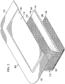
- FIGURE 1 an illustrative embodiment of a wound dressing 102 is presented.
- the wound dressing 102 is shown on a wound 104, or tissue site.
- the wound is through a patient's 106 epidermis 108, a dermis 109, and into subcutaneous tissue 110.
- the wound dressing 102 includes a thermally-conductive, vapor-permeable member 112 and a liquid-processing member 114. While referencing only "vapor" in its name, the thermally-conductive, vapor-permeable member 112 is operable to allow vapor and liquid to pass.
- the thermally-conductive, vapor-permeable member 112 and liquid-processing member 114 are covered by a high-moisture-vapor-transmission-rate drape 116 (high-MVTR drape).
- the thermally-conductive, vapor-permeable member 112 is operable to conduct body heat from the patient 106 at or near the wound 104 to the high-moisture-vapor-transmission-rate drape 116 to enhance transmission of vapor through the high-moisture-vapor-transmission-rate drape 116.
- the heat captured by the thermally-conductive, vapor-permeable member 112 of the wound dressing 102 and delivered specifically to the high-moisture-vapor-transmission-rate drape 116 increases vapor transmission through the high-moisture-vapor-transmission-rate drape 116.
- other sources of internal and external heat may be utilized with the wound dressing 102 to increase vapor transmission through the high-moisture-vapor-transmission-rate drape 116.
- Enhancing the vapor transmission through the wound dressing 102 maximizes the capacity of the wound dressing 102.
- the wound dressing 102 becomes operable to process more liquid over time than the wound dressing 102 can hold at one time.
- the wound dressing 102 effectually removes or manages liquid from the wound 104.
- the increased vapor transmission can be notable. For example, increasing the temperature from 20° C to 30° C or 40° C may add orders of magnitude to the evaporation rate. In one illustrative, non-limiting example, a 1.3 fold increase in evaporation rate per degree was associated with each degree increase in Celsius (C) from 25° C to 37° C.
- the increased evaporation rate in turn may greatly enhance the amount of liquid from the wound 104 that may be processed over time by the wound dressing 102.
- the high-moisture-vapor-transmission-rate drape 116 has a first side 118 and a second, patient-facing side 120.
- "Moisture Vapor Transmission Rate” or “MVTR” represents the amount of moisture that can pass through a material in a given period of time.
- the high-moisture-vapor-transmission-rate drape 116 will typically have an MVTR greater than 300g/24 hours/m 2 and more typically a value greater than or equal to 1000g/24 hours/m 2 .
- the high-moisture-vapor-transmission-rate drape 116 allows vapor to egress from the wound through the wound dressing 102 to the atmosphere.
- the high-moisture-vapor-transmission-rate drape 116 may comprise any of numerous materials, such as any of the following: hydrophilic polyurethane, cellulosics, hydrophilic polyamides, polyvinyl alcohol, polyvinyl pyrrolidone, hydrophilic acrylics, hydrophilic silicone elastomers, and copolymers of these.
- the high-moisture-vapor-transmission-rate drape 116 may be formed from a breathable cast matt polyurethane film sold under the name INSPIRE 2301 from Expopack Advanced Coatings of Wrexham, United Kingdom.
- That illustrative film has a MVTR (inverted cup technique) of 14400 g/m 2 /24 hours.
- the high-moisture-vapor-transmission-rate drape 116 may have various thicknesses, such as 10 to 40 microns ( ⁇ m), e.g., 15, 20, 25, 30, 35, 40 microns or any number in the stated range.
- a peripheral edge 122 of the high-moisture-vapor-transmission-rate drape 116 has an attachment device 124 on the second, patient-facing side 120.
- the attachment device 124 secures or helps secure the high-moisture-vapor-transmission-rate drape 116 to the patient's intact skin at or near the wound 104.
- the attachment device 124 may be a medically-acceptable, pressure-sensitive adhesive; a double-sided drape tape; paste; hydrocolloid; hydro gel; or other sealing devices or elements.
- the thermally-conductive, vapor-permeable member 112 functionally conducts heat from the patient 106 at or near the wound 104 to the high-moisture-vapor-transmission-rate drape 116 and allows or enhances vapor transmission through the thermally-conductive, vapor-permeable member 112. While the thermally-conductive, vapor-permeable member 112 may be formed as integral components, the thermally-conductive, vapor-permeable member 112 may nonetheless be viewed as comprising three portions or members: a drape-interface member 126, a patient-interface member 128, and a coupling member 130.
- the drape-interface member 126 has a first side 132 and a second, patient-facing side 134.
- the first side 132 of the drape-interface member 126 is proximate the second, patient-facing side 120 of the high-moisture-vapor-transmission-rate drape 116.
- the patient-interface member 128 has a first side 136 and a second, patient-facing side 138.
- the second, patient-facing side 138 of the patient-interface member 128 is proximate to the patient 106.
- the coupling member 130 thermally couples the drape-interface member 126 and the patient-interface member 128.
- the thermally-conductive, vapor-permeable member 112 may be formed from any material that conducts thermal energy and allows liquid and vapor to transgress the material.
- the thermally-conductive, vapor-permeable member 112 may comprise one or more of the following: woven or non-woven material, activated carbon material, porous foam, sintered polymer, carbon fiber material, woven metallic fibers, zinc oxide, or mesh fabric.
- the thermally-conductive, vapor-permeable member 112 is sized and configured to be flexible enough to conform to the shape of the wound 104.
- the liquid-processing member 114 Disposed between the drape-interface member 126 and the patient-interface member 128 is the liquid-processing member 114.
- the liquid-processing member 114 is operable to at least temporarily retain liquids from the wound 104.
- the liquid-processing member 114 has a first side 140 and a second, patient-facing side 142.
- the first side 140 is proximate the second, patient-facing side 134 of the drape-interface member 126.
- the second, patient-facing side 142 is proximate to the first side 136 of the patient-interface member 128.
- the liquid-processing member 114 functions to retain, at least temporarily, liquids from the wound 104.
- the liquid-processing member 114 buffers liquids while waiting on evaporation or removal or may store a certain quantity of liquids for other reasons.
- the liquid-processing member 114 may be formed from one or more of the following: open-cell foam, non-woven material, a super-absorbent material, gel materials, absorbent clays or inorganic or polymer particulates, and nano particles.
- thermal energy may be added to enhance evaporation from an internal heat source or external heat source.
- heat from external air temperature, light, artificial radiation (infrared), hydro-activated chemicals, inductive materials, piezoelectric members, electric heating elements, or sonic heating (thermo-acoustic) may be used to enhance transmission of vapor through the high-moisture-vapor-transmission-rate drape 116.
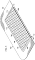
- a plurality of nano-antennas 144 or nantennas have been added on the first side 118 of the high-moisture-vapor-transmission-rate drape 116.
- the plurality of nano-antennas 144 are a way of harvesting the environmental energy, e.g., energy from light or heat from the patient.
- a nano-antenna is an electromagnetic collector designed to absorb specific wavelengths that are proportional to the size of the nano-antenna.
- the nano-atennas 144 may be sized to focus on absorbing infrared radiation with wavelengths from 1 micron to 300 microns and may, in some embodiments, focus on 12 micron wavelengths which are the wavelength that the human body at normal temeprature emits as heat.
- Design of the nano-antenna 144 may be a type of interlocking spiral such as those from MicroContinuum Inc. These type of antennas are manufactured by photo-lithography using gold foil on a plastic sheet substrate. The energy harnessed is electrical.
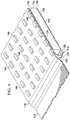
- the high-moisture-vapor-transmission-rate drape 116 may include corrugated portions 146 as shown in FIGURE 6 .
- the corrugated portions 146 increase the surface area available to assist with evaporation and may encourage turbulent air flow across the first side 118 of the high-moisture-vapor-transmission-rate drape 116.
- the thermally-conductive, vapor-permeable member 112 which has the liquid-processing member 114 between portions thereof, is disposed proximate to the wound 104.
- the patient-interface member 128 of the thermally-conductive, vapor-permeable member 112 is disposed proximate to the wound 104.
- the high-moisture-vapor-transmission-rate drape 116 is disposed over the thermally-conductive, vapor-permeable member 112.
- the second, patient-facing side 120 of the high-moisture-vapor-transmission-rate drape 116 is disposed proximate to the first side 132 of the drape-interface member 126.
- release liners may be removed from the attachment device 124.
- the wound dressing 102 may remain on the wound 104 for a few hours up to many days, e.g., 2 days, 4 days, 7 days, or more.
- a saturation indicator (visual indicator of moisture)(not shown) may be added to the thermally-conductive, vapor-permeable member 112 or liquid-processing member 114 to indicate when the wound dressing 102 is full.
- nano-antennas 144 are included (e.g., FIGS. 3-4 , 6 , 12 ), the nano-antennas 144 may absorb energy from ambient light or may receive light from a directed light source (see, e.g., FIG. 12 ).
- the wound 104 produces a liquid, e.g., exudate, that flows through the patient-interface member 128 and into the liquid-processing member 114, which temporarily holds the liquid.
- the liquid in the liquid-processing member 114 that is against or near the high-moisture-vapor-transmission-rate drape 116 evaporates and is transmitted through the high-moisture-vapor-transmission-rate drape 116.
- the transmission rate through the high-moisture-vapor-transmission-rate drape 116 is increased or enhanced by the thermal energy delivery from the patient 106 through the thermally-conductive, vapor-permeable member 112.
- the transmission rate may further be enhanced by additional energy added externally or internally as presented elsewhere herein.
- FIGURE 5 a cross section of a portion of a wound dressing 102 is shown according to one illustrative embodiment.
- This embodiment is analogous to the embodiment of FIGURE 1 , except a filtering layer 148 has been added.
- the filtering layer 148 is shown disposed between the high-moisture-vapor-transmission-rate drape 116 and the drape-interface member 126 of the thermally-conductive, vapor-permeable member 112. It should be understood that the filtering layer 148 may be at any location between the patient and the high-moisture-vapor-transmission-rate drape 116. It should also be understood that filtering layer 148 may be used with any embodiment herein.
- the filtering layer 148 may serve one or more purposes.
- the filtering layer 148 may prevent any substances other than water vapor from reaching the high-moisture-vapor-transmission-rate drape 116.
- the filtering layer 148 may serve to filter odors from the vapor transmitted through the high-moisture-vapor-transmission-rate drape 116 to the atmosphere.
- the filtering layer may be formed from activated carbon material, activated clays (such as Bentonite), silicone resins, or coated porous (foams, sintered media) elements.
- FIGURE 6 an illustrative embodiment of a portion of a wound dressing 102 is shown that is analogous to the wound dressing 102 of FIGURE 1 , except that the high-moisture-vapor-transmission-rate drape 116 includes corrugated portions 146 and nano-antennas 144 and the wound dressing 102 includes a hydro-activated, exothermic material 150.
- the corrugated portions 146 and nano-antennas 144 have previously been discussed.
- the hydro-activated, exothermic material 150 may be disposed on or in the liquid-processing member 114 near the drape-interface member 126. When the hydro-activated, exothermic material 150 is exposed to a watery liquid, a resultant chemical reaction produces heat.
- the hydro-activated, exothermic material 150 may be calcium oxide such that when water in the exudate reaches the hydro-activated, exothermic material 150 a reaction occurs: CaO(s) + H2O(1) ⁇ Ca(OH)2(s).
- CaO(s) + H2O(1) ⁇ Ca(OH)2(s) is another example, albeit a highly exothermic (and more caustic) one, is NaO (s) + H 2 O (1) ⁇ NaOH (s) .
- Another example (used in hand warmers for example) is 4Fe (s) + 30 2(g) ⁇ 2Fe 2 O 3(s) . This reaction is one way, but a reversible reaction may be used as well.
- FIGURE 7 an illustrative embodiment of a portion of a wound dressing 102 that includes an internal heat source in the form of an electrical heating element 152 is presented.
- the wound dressing 102 is analogous in most respects to the wound dressing of FIGURE 1 , except that it further includes the electrical heating element 152 and associated components.
- the electrical heating element 152 may be a resistive heating element that is disposed inside or on the thermally-conductive, vapor-permeable member 112 and is thereby thermally coupled to the high-moisture-vapor-transmission-rate drape 116.
- the electrical heating element 152 provides thermal energy when energized.
- the illustrative electrical heating element 152 is shown as a plurality of electrical conduits disposed within the thermally-conductive, vapor-permeable member 112 and electrically coupled to one another by leads 154.
- the electrical heating element 152 is electrically coupled to a control circuit 156 by another lead 158.
- a power supply 160 is electrically coupled to the control circuit 156 by another lead 162.
- the control circuit 156 may be used to set the desired temperature and to control the heat developed by the electrical heating element 152.
- FIGURE 8 an illustrative embodiment of a portion of a wound dressing 102 that includes an internal heat source in the form of a piezoelectric member 164 is shown.
- the wound dressing 102 is analogous in most respects to the wound dressing of FIGURE 1 , except that the wound dressing 102 further includes the piezoelectric member 164.
- the piezoelectric member 164 is operable to provide energy to the wound dressing 102 when the piezoelectric member 164 is moved.
- the piezoelectric member 164 generates an electrical current during flexing that is then used to generate heat.
- FIGURE 9 an illustrative embodiment of a portion of a wound dressing 102 that includes inductive elements 166 and a source of magnetic energy 168 is presented.
- the wound dressing 102 is analogous in most respects to the wound dressing of FIGURE 1 , except the inductive elements 166 have been added.
- the inductive elements 166 are disposed within or on the thermally-conductive, vapor-permeable member 112.
- the source of magnetic energy 168 emits magnetic energy that is received by the inductive elements 166 to produce thermal energy that is conducted to the thermally-conductive, vapor-permeable member 112 and thereby to the high-moisture-vapor-transmission-rate drape 116.
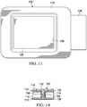
- FIGURES 10 and 11 an illustrative embodiment of a wound dressing 102 is presented that is analogous in most respects to the wound dressing 102 of FIGURE 1 , except that the wound dressing 102 includes a patient-interface member 128 that is larger than the drape-interface member 126 of the thermally-conductive, vapor-permeable member 112.
- the patient-interface member 128 is larger to provide a greater surface area over which to capture heat from the patient.
- a seal 170 may be provided on a portion of the patient-interface member 128 proximate to an edge of the drape-interface member 126 to provide a fluid seal. The seal inhibits fluid flow but allows thermal energy to pass.
- the planar surface area (A 1 ) of the drape-interface member 126 is less than the planar surface area (A 2 ) of the patient-interface member 128, i.e., A 1 ⁇ A 2 .
- An adhesive (not shown) may be applied on peripheral portion of the patient-facing side of the patient-interface member 128 to hold the additional portion of the patient-interface member 128 to intact skin on the patient.
- the wound dressing 102 is disposed proximate to the wound 104.
- the patient-interface member 128 is proximate to the wound 104.
- the other layers or members are assembled or pre-assembled as shown in the figures with the high-moisture-vapor-transmission-rate Drape on the top (for the orientation shown).
- the vapor leaving the thermally-conductive, vapor-permeable member 112 moves through the filtering layer 148, which removes odor or particulates that might otherwise escape.
- the vapor transmission rate is enhanced by the patient's body heat and heat from the hydro-activated, exothermic material 150 once the watery liquid reaches the hydro-activated, exothermic material 150.
- the transmission rate may be relatively increased by using a greater surface area due to the corrugated portions 146.
- the transmission rate is enhanced by the patient's body heat and heat from the electrical heating element 152.
- the amount of heat added by the electrical heating element 152 is controlled by the control circuit or controller 156.
- An electrical fill indicator (not shown) may be included in the liquid-processing member 114 and electrically coupled to the control circuit 156 such that the control circuit 156 activates the electrical heating element 152 once the liquid-processing member 114 is saturated.
- the control circuit 156 may activate the electrical heating element 152 based on timer intervals or when manually activated.
- the transmission rate is enhanced by the patient's body heat and heat from the piezoelectric member 164.
- the piezoelectric member 164 may take movement and create thermal energy.
- the element labeled 164 may be a material that otherwise generates heat as the element is flexed.
- castable polyester polyurethane elastomers based on the system polycaprolactone diol (Capa 225)/trans 1.4-cyclohexane diisocyanate (CHDI)/1.4-butane diol (1.4-BD) and 1.4-cyclohexane dimethanol (1.4-CHDM).
- CHDI system polycaprolactone diol
- 1.4-BD 1.4-cyclohexane diisocyanate
- 1.4-CHDM 1.4-cyclohexane dimethanol
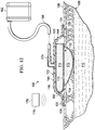
- the system 100 includes a wound dressing 102, which is analogous in many respects to the wound dressing 102 of FIGURE 1 .
- the system 100 provides for enhanced liquid management and also for the application of reduced pressure on a wound 104.
- the system 100 includes a manifold member 172 disposed proximate to the wound 104.
- the wound 104 extends through epidermis 108, dermis 109, and into subcutaneous tissue 110.
- the manifold member 172 is a substance or structure that is provided to assist in applying reduced pressure to, delivering fluids to, or removing fluids from a tissue site or wound 104.
- the manifold member 172 includes a plurality of flow channels or pathways that distribute fluids provided to and removed from the tissue site around the manifold member 172. In one illustrative embodiment, the flow channels or pathways are interconnected to improve distribution of fluids provided to or removed from the wound 104.
- the manifold member 172 may be a biocompatible material that is capable of being placed in contact with the wound 104 and distributing reduced pressure.
- manifold members 172 include, without limitation, one or more of the following: devices that have structural elements arranged to form flow channels, such as, for example, cellular foam, open-cell foam, porous tissue collections, liquids, gels, and foams that include, or cure to include, flow channels; porous material porous, such as foam, gauze, felted mat, or any other material suited to a particular biological application; or porous foam that includes a plurality of interconnected cells or pores that act as flow channels, e.g., a polyurethane, open-cell, reticulated foam such as GranuFoam® material manufactured by Kinetic Concepts, Incorporated of San Antonio, Texas; a bioresorbable material; or a scaffold material.
- devices that have structural elements arranged to form flow channels such as, for example, cellular foam, open-cell foam, porous tissue collections, liquids,
- the manifold member 172 may also be used to distribute fluids such as medications, antibacterials, growth factors, and various solutions to the tissue site.
- Other layers may be included in or on the manifold member 172, such as absorptive materials, wicking materials, hydrophobic materials, and hydrophilic materials.
- the manifold member 172 may be constructed from a bioresorbable material that remains in a patient's body following use of the reduced-pressure dressing. Suitable bioresorbable materials include, without limitation, a polymeric blend of polylactic acid (PLA) and polyglycolic acid (PGA).
- the polymeric blend may also include without limitation polycarbonates, polyfumarates, and capralactones.
- the manifold member 172 may further serve as a scaffold for new cell-growth, or a scaffold material may be used in conjunction with the manifold member 172 to promote cell-growth.
- a scaffold is a substance or structure used to enhance or promote the growth of cells or formation of tissue, such as a three-dimensional porous structure that provides a template for cell growth.
- Illustrative examples of scaffold materials include calcium phosphate, collagen, PLA/PGA, coral hydroxy apatites, carbonates, or processed allograft materials.
- the wound dressing 102 includes a high-moisture-vapor-transmission-rate drape 116; a thermally-conductive, vapor-permeable member 112; and a liquid-processing member 114.
- the high-moisture-vapor-transmission-rate drape 116 may include nano-antennas 144.
- Applied on or through the high-moisture-vapor-transmission-rate drape 116 is a reduced-pressure interface 174.
- the reduced-pressure interface 174 is a T.R.A.C.® Pad or Sensa T.R.A.C.®Pad available from KCI of San Antonio, Texas.
- An external energy source 176 may be used to provide additional energy to the wound dressing 102.
- the external energy source 176 may be a light source 178, e.g., an LED light, that provides light to the high-moisture-vapor-transmission-rate drape 116 directly or by providing energy to the nano-antennas 144.
- the high-moisture-vapor-transmission-rate drape 116 creates a sealed space 180 between the wound 104 and the second, patient-facing side 120 of the high-moisture-vapor-transmission-rate drape 116.
- a reduced-pressure source 182 is fluidly coupled to the sealed space 180.
- the reduced-pressure source 182 may be any device for supplying a reduced pressure, such as a vacuum pump, wall suction, micro-pump, or other source.
- the reduced pressure will typically be between -5 mm Hg (-667 Pa) and -500 mm Hg (-66.7 kPa) and more typically between -75 mm Hg (-9.9 kPa) and -300 mm Hg (-39.9 kPa).
- the reduced-pressure source 182 may be fluidly coupled to the sealed space 180, which includes the manifold member 172, by a reduced-pressure delivery conduit 184 and the reduced-pressure interface 174 or by directly inserting the reduced-pressure delivery conduit 184 through the high-moisture-vapor-transmission-rate drape 116 into the sealed space 180.
- the fluid coupling may be due to the position of the reduced-pressure source 182; for example, if the reduced-pressure source 182 is a micro-pump, the intake may be directly, fluidly coupled to the sealed space 180.
- the micro-pump is thermally coupled to the high-moisture-vapor-transmission-rate drape 116.
- the manifold member 172 is disposed proximate to the wound 104.
- the wound dressing 102 is placed proximate to a first side 173 of the manifold member 172.
- the high-moisture-vapor-transmission-rate drape 116 over the patient's skin creates the sealed space 180.
- the reduced-pressure delivery conduit 184 is fluidly coupled to the sealed space 180 and thereby the manifold member 172. Reduced pressure is then applied to help treat the wound 102.
- liquids are delivered to the reduced-pressure source 182, but evaporation and transmission through the high-moisture-vapor-transmission-rate drape 116 may also occur.
- the liquid will be retained in the wound dressing 102 until transmitted through the high-moisture-vapor-transmission-rate drape 116.
- the transmission rate is enhanced by the patient's body heat (delivered through the thermally-conductive, vapor-permeable member 112) and may be enhanced by nano-antennas 144 if included.
- the nano-antennas 144 may be energized by a light source 178.
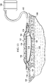
- FIGURE 13 another illustrative embodiment of a wound dressing 102 is presented.
- the wound dressing 102 is analogous in most respects to the wound dressing 102 of FIGURE 1 , except external baffles 186 and an air mover 188 have been added.
- the external baffles 186 are on the first side of the high-moisture-vapor-transmission-rate drape 116 and form a channel 190.
- the air mover 188 is fluidly coupled to the channel 190 by a conduit 192.
- the air mover 188 provides air flow against the first side 118 of the high-moisture-vapor-transmission-rate drape 116 and thereby further increases the evaporation rate.
- the components of the various figures may be combined with others. Thus, for example, the air mover 188 and external baffles 186 may be added to any of the other embodiments herein.
- FIGURE 14 another illustrative embodiment of a portion of a wound dressing 102 is presented.
- the wound dressing 102 is analogous in most respects to the wound dressing 102 of FIGURE 1 .
- the wound dressing 102 has a thermally-conductive, vapor-permeable member 112.
- a liquid-processing member 114 is between portions of the thermally-conductive, vapor-permeable member 112.
- the wound dressing 102 further includes a high-moisture-vapor-transmission-rate drape 116.
- the thermally-conductive, vapor-permeable member 112 has a drape-interface member 126, a patient-interface member 128, and a coupling member 130.
- the coupling member 130 is presented in a different location in part to emphasize that the coupling member 130 may be in numerous locations.
- the coupling member 130 has been to one side of the liquid-processing member 114.
- the coupling member 130 extends from the patient-interface member 128 to the drape-interface member 126 through the body or main portion of the liquid-processing member 114. Because it is generally desirable to transfer heat from the patient to the drape-interface member 126 without heating up the liquid-processing member 114, insulation 194 may be placed around the coupling member 130. It should be understood that the coupling member 130 functions to thermally couple the drape-interface member 126 and the patient-interface member 128 and may be located at any point with respect to those members, e.g., sides or middle or any where between.
- any feature that is described in connection to any one embodiment may also be applicable to any other embodiment.
- the nano-antennas 144 may be added to any embodiment herein.
- the filtering layer 148 may be added to any embodiment herein.
- the corrugated portions 146 may be added to any of the embodiments herein.
- the hydro-activated, exothermic material 150 may be added to any of the embodiments herein.
- the electrical heating element 152 (and associated components) may be added to any embodiment herein or the piezoelectric member 164 added to any embodiment.
- reduced pressure may be used with any of the embodiments.
- the external baffles 186 and air mover 188 ( FIG. 13 ) may be used with any embodiment.
- the different components may be used in any combination.
- a wound dressing 102 may have a nano-antennas 144 on the high-moisture-vapor-transmission-rate drape 116, a filtering layer 148 below (for orientation shown in FIG. 5 ), a hydro-activated, exothermic material 150 proximate the filtering layer 148, and an electrical heating element 152 in the thermally-conductive, vapor-permeable member 112.
- a nano-antennas 144 on the high-moisture-vapor-transmission-rate drape 116
- a filtering layer 148 below for orientation shown in FIG. 5
- a hydro-activated, exothermic material 150 proximate the filtering layer 148
- an electrical heating element 152 in the thermally-conductive, vapor-permeable member 112.
- the piezoelectric member 164 ( FIG. 8 ) may be included with the reduced-pressure components of FIGURE 12 . Then in operation, the reduced-pressure components may be used in a pulsed fashion to move and excite the piezoelectric member 164 to generate heat.
- the wound dressing 102 may have an enhanced capacity because the wound dressing 102 is able to offload liquid from the wound dressing 102 in the form of vapor exiting the wound dressing 102 through the high-moisture-vapor-transmission-rate drape 116. And, because of the additional thermal energy, the wound dressings 102 are operable to transmit relatively more liquid through the high-moisture-vapor-transmission-rate drape 116 over a given time. Moreover, the wound dressings 102 may stay in place longer. The wound dressings 102 may be used without requiring additional training. The wound dressings 102 may convert liquids retained into the wound dressing 102 to a gel and thereby make disposal easier.
Claims (14)
- Wundverband (102), umfassend:ein Abdecktuch (116) mit hoher Feuchtigkeit-Dampf-Übertragungsrate, das eine erste Seite (118) und eine zweite, einem Patienten zugewandte Seite (120) aufweist;ein wärmeleitendes, dampfdurchlässiges Element (112), umfassend:ein Abdecktuch-Grenzflächenelement (126), das eine erste Seite (132) und eine zweite, einem Patienten zugewandte Seite (134) aufweist, wobei die erste Seite (132) des Abdecktuch-Grenzflächenelements (126) benachbart zu der zweiten, einem Patienten zugewandten Seite (120) des Abdecktuchs (116) mit hoher Feuchtigkeit-Dampf-Übertragungsrate ist,ein Patient-Grenzflächenelement (128), das eine erste Seite (136) und eine zweite, einem Patienten zugewandte Seite (138) aufweist, wobei die zweite, einem Patienten zugewandte Seite (138) des Patient-Grenzflächenelements (128) benachbart zu einem Patienten (106) ist, undein Kopplungsbauteil (130), das das Abdecktuch-Grenzflächenelement (126) und das Patient-Grenzflächenelement (128) thermisch koppelt;ein Flüssigkeit-Verarbeitungselement (114), das zwischen dem Abdecktuch-Grenzflächenelement (126) und dem Patient-Grenzflächenelement (128) angeordnet ist, wobei das Flüssigkeit-Verarbeitungselement (114) betreibbar ist, um zumindest vorübergehend Flüssigkeiten von der Wunde (104) zurückzuhalten; undwobei das wärmeleitende, dampfdurchlässige Element (112) betreibbar ist, um Körperwärme von dem Patienten (106) zu dem Abdecktuch (116) mit hoher Feuchtigkeit-Dampf-Übertragungsrate zu leiten, um die Übertragung von Dampf durch das Abdecktuch (116) mit hoher Feuchtigkeit-Dampf-Übertragungsrate zu verbessern;wobei das wärmeleitende, dampfdurchlässige Element (112) ein Aktivkohleelement oder ein Material mit metallischen Fasern, Zinkoxid oder Silber umfasst.
- Wundverband (102) nach Anspruch 1, weiter umfassend eine Filterschicht (148), die zwischen zumindest einem Abschnitt des Flüssigkeit-Verarbeitungselements (114) und dem wärmeleitenden, dampfdurchlässigen Element (112) angeordnet ist.
- Wundverband (102) nach Anspruch 1 oder einem der vorstehenden Ansprüche, weiter umfassend Nano-Antennen (144), die mit der ersten Seite des Abdecktuchs (116) mit hoher Feuchtigkeit-Dampf-Übertragungsrate zum Empfangen externer Energie gekoppelt sind, wobei die Nano-Antennen (144) elektromagnetische Kollektoren sind, die gestaltet sind, um spezifische Wellenlängen, die proportional zu der Größe der Nano-Antennen (144) sind, zu absorbieren.
- Wundverband (102) nach Anspruch 1 oder einem der vorstehenden Ansprüche, wobei das Abdecktuch (116) mit hoher Feuchtigkeit-Dampf-Übertragungsrate zumindest teilweise gewellt (146) ist.
- Wundverband (102) nach Anspruch 1 oder einem der vorstehenden Ansprüche, wobei das Flüssigkeit-Verarbeitungselement (114) ein hydroaktiviertes exothermes Material umfasst, das mit dem Exsudat der Wunde (104) reagiert, um Wärme zu erzeugen, oder ein Kalziumoxid umfasst, das exotherm mit dem Exsudat der Wunde reagiert, um Wärme zu erzeugen.
- Wundverband (102) nach Anspruch 1 oder einem der vorstehenden Ansprüche, weiter umfassend:ein elektrisches Heizelement (152), das betreibbar ist, um Wärmeenergie bereitzustellen, wenn es aktiviert ist, wobei das elektrische Heizelement mit dem Abdecktuch (116) mit hoher Feuchtigkeit-Dampf-Übertragungsrate thermisch gekoppelt ist;eine Stromversorgung (160), die mit dem elektrischen Heizelement (152) elektrisch gekoppelt ist; undeine Steuerschaltung (156), die mit der Stromversorgung (160) und dem elektrischen Heizelement (152) gekoppelt ist.
- Wundverband (102) nach Anspruch 1 oder einem der vorstehenden Ansprüche, weiter umfassend ein piezoelektrisches Element (164), das betreibbar ist, um Wärmeenergie bereitzustellen, wenn es bewegt wird, wobei das piezoelektrische Element (164) mit dem Abdecktuch (116) mit hoher Feuchtigkeit-Dampf-Übertragungsrate thermisch gekoppelt ist.
- Wundverband (102) nach einem der Ansprüche 1-7, weiter umfassend:ein Verteilerelement (172), das benachbart zu dem Patient-Grenzflächenelement (128) des wärmeleitenden, dampfdurchlässigen Elements (112) angeordnet ist; undeine Quelle (182) verringerten Drucks, die mit dem Verteilerelement (172) strömungsmäßig gekoppelt ist, wobei die Quelle verringerten Drucks eine Mikropumpe umfasst, die mit dem Abdecktuch (116) mit hoher Feuchtigkeit-Dampf-Übertragungsrate gekoppelt ist, und wobei die Mikropumpe mit dem Abdecktuch (116) mit hoher Feuchtigkeit-Dampf-Übertragungsrate thermisch gekoppelt ist, um Wärme dorthin zu liefern.
- Wundverband (102) nach Anspruch 1 oder einem der vorstehenden Ansprüche, wobei ein ebener Oberflächenbereich des Abdecktuch-Grenzflächenelements (126) geringer ist als ein ebener Oberflächenbereich des Patient-Grenzflächenelements (128).
- Wundverband (102) nach Anspruch 1 oder einem der vorstehenden Ansprüche, weiter umfassend ein durch Bewegung aktiviertes Heizelement, das mit dem Abdecktuch (116) mit hoher Feuchtigkeit-Dampf-Übertragungsrate thermisch gekoppelt ist.
- Wundverband (102) nach Anspruch 1 oder einem der vorstehenden Ansprüche, weiter umfassend eine externe Heizvorrichtung zum Übertragen von Wärme auf die erste Seite des Abdecktuchs (116) mit hoher Feuchtigkeit-Dampf-Übertragungsrate.
- Wundverband (102) nach Anspruch 1 oder einem der vorstehenden Ansprüche, weiter umfassend externe Leitbleche (186) auf der ersten Seite des Abdecktuchs (116) mit hoher Feuchtigkeit-Dampf-Übertragungsrate und eine Luftbewegungsvorrichtung (188) zum Bereitstellen einer Luftströmung in den Leitblechen (186).
- Verfahren zum Herstellen eines Wundverbands (102), wobei das Verfahren die Schritte umfasst, von:
Bereitstellen eines wärmeleitenden, dampfdurchlässigen Elements (112), umfassend:ein Abdecktuch-Grenzflächenelement (126), das eine erste Seite (132) und eine zweite, einem Patienten zugewandte Seite (134) aufweist,ein Patient-Grenzflächenelement (128), das eine erste Seite (136) und eine zweite, einem Patienten zugewandte Seite (138) aufweist, wobei die zweite, einem Patienten zugewandte Seite (138) des Patient-Grenzflächenelements (128) zum Platzieren benachbart zu dem Patienten (106) vorgesehen ist, undein Kopplungsbauteil (130), das das Abdecktuch-Grenzflächenelement (126) und das Patient-Grenzflächenelement (128) thermisch koppelt;Anordnen eines Flüssigkeit-Verarbeitungselement (114) zwischen dem Abdecktuch-Grenzflächenelement (126) und dem Patient-Grenzflächenelement (128), wobei das Flüssigkeit-Verarbeitungselement (114) betreibbar ist, um zumindest vorübergehend Flüssigkeiten von der Wunde (104) zurückzuhalten; undAnordnen eines Abdecktuchs (116) mit hoher Feuchtigkeit-Dampf-Übertragungsrate, das eine erste Seite (118) und eine zweite, einem Patienten zugewandte Seite (120) aufweist, über dem wärmeleitenden, dampfdurchlässigen Element (112), wobei die erste Seite (132) des Abdecktuch-Grenzflächenelements (126) benachbart zu der zweiten, einem Patienten zugewandte Seite (120) des Abdecktuchs (116) mit hoher Feuchtigkeit-Dampf-Übertragungsrate ist;wobei das wärmeleitende, dampfdurchlässige Element (112) ein Aktivkohleelement oder ein Material mit metallischen Fasern, Zinkoxid oder Silber umfasst. - Verfahren nach Anspruch 13, weiter umfassend ein Koppeln von Nano-Antennen (144) mit der ersten Seite des Abdecktuchs (116) mit hoher Feuchtigkeit-Dampf-Übertragungsrate, wobei die Nano-Antennen (144) elektromagnetische Kollektoren sind, die gestaltet sind, um spezifische Wellenlängen, die proportional zu der Größe der Nano-Antennen (144) sind, zu absorbieren.
Priority Applications (1)
| Application Number | Priority Date | Filing Date | Title |
|---|---|---|---|
| EP20156978.7A EP3669841B1 (de) | 2011-11-15 | 2012-11-15 | Medizinische verbände, systeme und verfahren mit thermisch optimierter dampfübertragung |
Applications Claiming Priority (2)
| Application Number | Priority Date | Filing Date | Title |
|---|---|---|---|
| US201161560090P | 2011-11-15 | 2011-11-15 | |
| PCT/US2012/065335 WO2013074825A1 (en) | 2011-11-15 | 2012-11-15 | Medical dressings, systems, and methods with thermally- enhanced vapor transmission |
Related Child Applications (1)
| Application Number | Title | Priority Date | Filing Date |
|---|---|---|---|
| EP20156978.7A Division EP3669841B1 (de) | 2011-11-15 | 2012-11-15 | Medizinische verbände, systeme und verfahren mit thermisch optimierter dampfübertragung |
Publications (2)
| Publication Number | Publication Date |
|---|---|
| EP2779975A1 EP2779975A1 (de) | 2014-09-24 |
| EP2779975B1 true EP2779975B1 (de) | 2020-02-19 |
Family
ID=47263602
Family Applications (2)
| Application Number | Title | Priority Date | Filing Date |
|---|---|---|---|
| EP12794613.5A Active EP2779975B1 (de) | 2011-11-15 | 2012-11-15 | Medizinische verbände, systeme und verfahren mit wärmeverstärkter dampfübertragung |
| EP20156978.7A Active EP3669841B1 (de) | 2011-11-15 | 2012-11-15 | Medizinische verbände, systeme und verfahren mit thermisch optimierter dampfübertragung |
Family Applications After (1)
| Application Number | Title | Priority Date | Filing Date |
|---|---|---|---|
| EP20156978.7A Active EP3669841B1 (de) | 2011-11-15 | 2012-11-15 | Medizinische verbände, systeme und verfahren mit thermisch optimierter dampfübertragung |
Country Status (7)
| Country | Link |
|---|---|
| US (3) | US9233028B2 (de) |
| EP (2) | EP2779975B1 (de) |
| JP (1) | JP6305927B2 (de) |
| CN (1) | CN103889378B (de) |
| AU (1) | AU2012340381B2 (de) |
| CA (1) | CA2854632C (de) |
| WO (1) | WO2013074825A1 (de) |
Families Citing this family (29)
| Publication number | Priority date | Publication date | Assignee | Title |
|---|---|---|---|---|
| GB0808376D0 (en) | 2008-05-08 | 2008-06-18 | Bristol Myers Squibb Co | Wound dressing |
| GB0817796D0 (en) | 2008-09-29 | 2008-11-05 | Convatec Inc | wound dressing |
| GB201020236D0 (en) | 2010-11-30 | 2011-01-12 | Convatec Technologies Inc | A composition for detecting biofilms on viable tissues |
| JP5965409B2 (ja) | 2010-12-08 | 2016-08-03 | コンバテック・テクノロジーズ・インコーポレイテッドConvatec Technologies Inc | 創傷滲出液を評価するための統合システム |
| ES2748519T3 (es) | 2010-12-08 | 2020-03-17 | Convatec Technologies Inc | Accesorio de sistema de exudado de heridas |
| EP2723286B2 (de) | 2011-06-24 | 2021-10-13 | KCI Licensing, Inc. | Wundauflagepflaster mit reduziertem druck mit verwendung von gewebefixierungselementen |
| GB201115182D0 (en) | 2011-09-02 | 2011-10-19 | Trio Healthcare Ltd | Skin contact material |
| GB2497406A (en) | 2011-11-29 | 2013-06-12 | Webtec Converting Llc | Dressing with a perforated binder layer |
| GB201120693D0 (en) | 2011-12-01 | 2012-01-11 | Convatec Technologies Inc | Wound dressing for use in vacuum therapy |
| USD733896S1 (en) | 2012-05-04 | 2015-07-07 | Genadyne Biotechnologies, Inc. | Abdominal dressing |
| EP2935688A2 (de) | 2012-12-20 | 2015-10-28 | ConvaTec Technologies Inc. | Verarbeitung von chemisch modifizierten cellulosefasern |
| US9579414B2 (en) * | 2013-07-08 | 2017-02-28 | Hossam Abdel Salam El Sayed Mohamed | Devices and methods for effecting faster healing of orthopedic and other wounds |
| US10226566B2 (en) | 2014-04-23 | 2019-03-12 | Genadyne Biotechnologies, Inc. | System and process for removing bodily fluids from a body opening |
| CA2972314A1 (en) | 2014-12-29 | 2016-07-07 | Smith & Nephew Plc | Negative pressure wound therapy apparatus and method of operating the apparatus |
| EP3262193A2 (de) | 2015-02-26 | 2018-01-03 | The Broad Institute Inc. | T-zellen-balance-genexpression, materialzusammensetzungen und verfahren zur verwendung davon |
| KR101698324B1 (ko) * | 2015-05-22 | 2017-01-20 | 주식회사 퓨처바이오웍스 | 전기 자극 습윤 드레싱 밴드 |
| CA3009878A1 (en) | 2015-12-30 | 2017-07-06 | Smith & Nephew Plc | Negative pressure wound therapy apparatus |
| ES2904480T3 (es) | 2016-03-30 | 2022-04-05 | Convatec Technologies Inc | Detección de infecciones microbianas en heridas |
| CN109564213B (zh) | 2016-03-30 | 2023-01-31 | 西诺福有限公司 | 检测伤口微生物感染 |
| ES2882336T3 (es) | 2016-07-08 | 2021-12-01 | Convatec Technologies Inc | Sistema flexible de presión negativa |
| EP3481348A4 (de) | 2016-07-08 | 2020-02-26 | ConvaTec Technologies Inc. | Vorrichtung zur entnahme von flüssigkeiten |
| JP6975770B2 (ja) | 2016-07-08 | 2021-12-01 | コンバテック・テクノロジーズ・インコーポレイテッドConvatec Technologies Inc | 流体流の感知 |
| CA3066093A1 (en) * | 2017-06-07 | 2018-12-13 | Kci Licensing, Inc. | Composite dressings for improved granulation and reduced maceration with negative-pressure treatment |
| WO2018226592A1 (en) | 2017-06-07 | 2018-12-13 | Kci Usa, Inc. | Wound dressing with odor absorption and increased moisture vapor transmission |
| WO2020014310A1 (en) * | 2018-07-13 | 2020-01-16 | Kci Licensing, Inc. | Advanced wound dressing with compression and increased total fluid handling |
| EP3829504B1 (de) * | 2018-08-03 | 2023-03-01 | KCI Licensing, Inc. | Flexibler und anpassbarer wundverband mit verbesserter flüssigkeitsaufnahmefähigkeit |
| US11771819B2 (en) | 2019-12-27 | 2023-10-03 | Convatec Limited | Low profile filter devices suitable for use in negative pressure wound therapy systems |
| US11331221B2 (en) | 2019-12-27 | 2022-05-17 | Convatec Limited | Negative pressure wound dressing |
| CN114469519B (zh) * | 2022-01-27 | 2022-08-05 | 长沙海润生物技术有限公司 | 一种负压耦合电场信号反馈治疗系统 |
Family Cites Families (176)
| Publication number | Priority date | Publication date | Assignee | Title |
|---|---|---|---|---|
| US1355846A (en) | 1920-02-06 | 1920-10-19 | David A Rannells | Medical appliance |
| US2547758A (en) | 1949-01-05 | 1951-04-03 | Wilmer B Keeling | Instrument for treating the male urethra |
| US2632443A (en) | 1949-04-18 | 1953-03-24 | Eleanor P Lesher | Surgical dressing |
| GB692578A (en) | 1949-09-13 | 1953-06-10 | Minnesota Mining & Mfg | Improvements in or relating to drape sheets for surgical use |
| US2682873A (en) | 1952-07-30 | 1954-07-06 | Johnson & Johnson | General purpose protective dressing |
| NL189176B (nl) | 1956-07-13 | 1900-01-01 | Hisamitsu Pharmaceutical Co | Pleister op basis van een synthetische rubber. |
| US2969057A (en) | 1957-11-04 | 1961-01-24 | Brady Co W H | Nematodic swab |
| US3066672A (en) | 1960-09-27 | 1962-12-04 | Jr William H Crosby | Method and apparatus for serial sampling of intestinal juice |
| US3367332A (en) | 1965-08-27 | 1968-02-06 | Gen Electric | Product and process for establishing a sterile area of skin |
| US3520300A (en) | 1967-03-15 | 1970-07-14 | Amp Inc | Surgical sponge and suction device |
| US3568675A (en) | 1968-08-30 | 1971-03-09 | Clyde B Harvey | Fistula and penetrating wound dressing |
| US3682180A (en) | 1970-06-08 | 1972-08-08 | Coilform Co Inc | Drain clip for surgical drain |
| BE789293Q (fr) | 1970-12-07 | 1973-01-15 | Parke Davis & Co | Pansement medico-chirugical pour brulures et lesions analogues |
| US3826254A (en) | 1973-02-26 | 1974-07-30 | Verco Ind | Needle or catheter retaining appliance |
| DE2527706A1 (de) | 1975-06-21 | 1976-12-30 | Hanfried Dr Med Weigand | Einrichtung zum einleiten von kontrastmittel in einen kuenstlichen darmausgang |
| DE2640413C3 (de) | 1976-09-08 | 1980-03-27 | Richard Wolf Gmbh, 7134 Knittlingen | Katheter-Überwachungsgerät |
| NL7710909A (nl) | 1976-10-08 | 1978-04-11 | Smith & Nephew | Samengestelde hechtstrook. |
| GB1562244A (en) | 1976-11-11 | 1980-03-05 | Lock P M | Wound dressing materials |
| US4080970A (en) | 1976-11-17 | 1978-03-28 | Miller Thomas J | Post-operative combination dressing and internal drain tube with external shield and tube connector |
| US4139004A (en) | 1977-02-17 | 1979-02-13 | Gonzalez Jr Harry | Bandage apparatus for treating burns |
| US4184510A (en) | 1977-03-15 | 1980-01-22 | Fibra-Sonics, Inc. | Valued device for controlling vacuum in surgery |
| US4165748A (en) | 1977-11-07 | 1979-08-28 | Johnson Melissa C | Catheter tube holder |
| US4256109A (en) | 1978-07-10 | 1981-03-17 | Nichols Robert L | Shut off valve for medical suction apparatus |
| SE414994B (sv) | 1978-11-28 | 1980-09-01 | Landstingens Inkopscentral | Venkateterforband |
| DE2953373A1 (en) | 1978-12-06 | 1981-01-08 | P Svedman | Device for treating tissues,for example skin |
| US4266545A (en) | 1979-04-06 | 1981-05-12 | Moss James P | Portable suction device for collecting fluids from a closed wound |
| US4284079A (en) | 1979-06-28 | 1981-08-18 | Adair Edwin Lloyd | Method for applying a male incontinence device |
| US4261363A (en) | 1979-11-09 | 1981-04-14 | C. R. Bard, Inc. | Retention clips for body fluid drains |
| US4569348A (en) | 1980-02-22 | 1986-02-11 | Velcro Usa Inc. | Catheter tube holder strap |
| EP0035583B1 (de) | 1980-03-11 | 1985-08-14 | Schmid, Eduard, Dr.Dr.med. | Hauttransplantations-Druckverband |
| US4297995A (en) | 1980-06-03 | 1981-11-03 | Key Pharmaceuticals, Inc. | Bandage containing attachment post |
| US4333468A (en) | 1980-08-18 | 1982-06-08 | Geist Robert W | Mesentery tube holder apparatus |
| US4465485A (en) | 1981-03-06 | 1984-08-14 | Becton, Dickinson And Company | Suction canister with unitary shut-off valve and filter features |
| US4392853A (en) | 1981-03-16 | 1983-07-12 | Rudolph Muto | Sterile assembly for protecting and fastening an indwelling device |
| US4373519A (en) | 1981-06-26 | 1983-02-15 | Minnesota Mining And Manufacturing Company | Composite wound dressing |
| US4392858A (en) | 1981-07-16 | 1983-07-12 | Sherwood Medical Company | Wound drainage device |
| US4419097A (en) | 1981-07-31 | 1983-12-06 | Rexar Industries, Inc. | Attachment for catheter tube |
| AU550575B2 (en) | 1981-08-07 | 1986-03-27 | Richard Christian Wright | Wound drainage device |
| SE429197B (sv) | 1981-10-14 | 1983-08-22 | Frese Nielsen | Anordning for behandling av sar |
| DE3146266A1 (de) | 1981-11-21 | 1983-06-01 | B. Braun Melsungen Ag, 3508 Melsungen | Kombinierte vorrichtung fuer eine medizinische saugdrainage |
| US4551139A (en) | 1982-02-08 | 1985-11-05 | Marion Laboratories, Inc. | Method and apparatus for burn wound treatment |
| US4475909A (en) | 1982-05-06 | 1984-10-09 | Eisenberg Melvin I | Male urinary device and method for applying the device |
| EP0100148B1 (de) | 1982-07-06 | 1986-01-08 | Dow Corning Limited | Medizinischer chirurgischer Wundverband und Verfahren zu seiner Herstellung |
| NZ206837A (en) | 1983-01-27 | 1986-08-08 | Johnson & Johnson Prod Inc | Thin film adhesive dressing:backing material in three sections |
| US4548202A (en) | 1983-06-20 | 1985-10-22 | Ethicon, Inc. | Mesh tissue fasteners |
| US4540412A (en) | 1983-07-14 | 1985-09-10 | The Kendall Company | Device for moist heat therapy |
| US4543100A (en) | 1983-11-01 | 1985-09-24 | Brodsky Stuart A | Catheter and drain tube retainer |
| US4525374A (en) | 1984-02-27 | 1985-06-25 | Manresa, Inc. | Treating hydrophobic filters to render them hydrophilic |
| GB2157958A (en) | 1984-05-03 | 1985-11-06 | Ernest Edward Austen Bedding | Ball game net support |
| US4897081A (en) | 1984-05-25 | 1990-01-30 | Thermedics Inc. | Percutaneous access device |
| US5215522A (en) | 1984-07-23 | 1993-06-01 | Ballard Medical Products | Single use medical aspirating device and method |
| GB8419745D0 (en) | 1984-08-02 | 1984-09-05 | Smith & Nephew Ass | Wound dressing |
| US4872450A (en) | 1984-08-17 | 1989-10-10 | Austad Eric D | Wound dressing and method of forming same |
| US4655754A (en) | 1984-11-09 | 1987-04-07 | Stryker Corporation | Vacuum wound drainage system and lipids baffle therefor |
| US4826494A (en) | 1984-11-09 | 1989-05-02 | Stryker Corporation | Vacuum wound drainage system |
| US4605399A (en) | 1984-12-04 | 1986-08-12 | Complex, Inc. | Transdermal infusion device |
| US5037397A (en) | 1985-05-03 | 1991-08-06 | Medical Distributors, Inc. | Universal clamp |
| US4640688A (en) | 1985-08-23 | 1987-02-03 | Mentor Corporation | Urine collection catheter |
| US4710165A (en) | 1985-09-16 | 1987-12-01 | Mcneil Charles B | Wearable, variable rate suction/collection device |
| US4758220A (en) | 1985-09-26 | 1988-07-19 | Alcon Laboratories, Inc. | Surgical cassette proximity sensing and latching apparatus |
| US4733659A (en) | 1986-01-17 | 1988-03-29 | Seton Company | Foam bandage |
| WO1987004626A1 (en) | 1986-01-31 | 1987-08-13 | Osmond, Roger, L., W. | Suction system for wound and gastro-intestinal drainage |
| US4838883A (en) | 1986-03-07 | 1989-06-13 | Nissho Corporation | Urine-collecting device |
| JPS62275456A (ja) * | 1986-05-22 | 1987-11-30 | 帝三製薬株式会社 | 創傷保護材 |
| JPS62281965A (ja) | 1986-05-29 | 1987-12-07 | テルモ株式会社 | カテ−テルおよびカテ−テル用固定部材 |
| GB8621884D0 (en) | 1986-09-11 | 1986-10-15 | Bard Ltd | Catheter applicator |
| GB2195255B (en) | 1986-09-30 | 1991-05-01 | Vacutec Uk Limited | Apparatus for vacuum treatment of an epidermal surface |
| US4743232A (en) | 1986-10-06 | 1988-05-10 | The Clinipad Corporation | Package assembly for plastic film bandage |
| DE3634569A1 (de) | 1986-10-10 | 1988-04-21 | Sachse Hans E | Kondomkatheter, ein harnroehrenkatheter zur verhinderung von aufsteigenden infektionen |
| JPS63135179A (ja) | 1986-11-26 | 1988-06-07 | 立花 俊郎 | 薬物の経皮投与具 |
| GB8628564D0 (en) | 1986-11-28 | 1987-01-07 | Smiths Industries Plc | Anti-foaming agent suction apparatus |
| GB8706116D0 (en) | 1987-03-14 | 1987-04-15 | Smith & Nephew Ass | Adhesive dressings |
| US4787888A (en) | 1987-06-01 | 1988-11-29 | University Of Connecticut | Disposable piezoelectric polymer bandage for percutaneous delivery of drugs and method for such percutaneous delivery (a) |
| GB8715421D0 (en) * | 1987-07-01 | 1987-08-05 | Charcoal Cloth Ltd | Wound dressing |
| US4863449A (en) | 1987-07-06 | 1989-09-05 | Hollister Incorporated | Adhesive-lined elastic condom cathether |
| US5176663A (en) | 1987-12-02 | 1993-01-05 | Pal Svedman | Dressing having pad with compressibility limiting elements |
| US4906240A (en) | 1988-02-01 | 1990-03-06 | Matrix Medica, Inc. | Adhesive-faced porous absorbent sheet and method of making same |
| US4985019A (en) | 1988-03-11 | 1991-01-15 | Michelson Gary K | X-ray marker |
| GB8812803D0 (en) | 1988-05-28 | 1988-06-29 | Smiths Industries Plc | Medico-surgical containers |
| US4919654A (en) | 1988-08-03 | 1990-04-24 | Kalt Medical Corporation | IV clamp with membrane |
| US5000741A (en) | 1988-08-22 | 1991-03-19 | Kalt Medical Corporation | Transparent tracheostomy tube dressing |
| JPH02270874A (ja) | 1989-01-16 | 1990-11-05 | Roussel Uclaf | アザビシクロ化合物及びそれらの塩、それらの製造方法、それらを含有する製薬組成物並びにそれらの薬剤としての使用 |
| GB8906100D0 (en) | 1989-03-16 | 1989-04-26 | Smith & Nephew | Laminates |
| US5100396A (en) | 1989-04-03 | 1992-03-31 | Zamierowski David S | Fluidic connection system and method |
| US4969880A (en) | 1989-04-03 | 1990-11-13 | Zamierowski David S | Wound dressing and treatment method |
| US5261893A (en) | 1989-04-03 | 1993-11-16 | Zamierowski David S | Fastening system and method |
| US5527293A (en) | 1989-04-03 | 1996-06-18 | Kinetic Concepts, Inc. | Fastening system and method |
| US5358494A (en) | 1989-07-11 | 1994-10-25 | Svedman Paul | Irrigation dressing |
| JP2719671B2 (ja) | 1989-07-11 | 1998-02-25 | 日本ゼオン株式会社 | 創傷被覆材 |
| US5232453A (en) | 1989-07-14 | 1993-08-03 | E. R. Squibb & Sons, Inc. | Catheter holder |
| GB2235877A (en) | 1989-09-18 | 1991-03-20 | Antonio Talluri | Closed wound suction apparatus |
| US5134994A (en) | 1990-02-12 | 1992-08-04 | Say Sam L | Field aspirator in a soft pack with externally mounted container |
| US5092858A (en) | 1990-03-20 | 1992-03-03 | Becton, Dickinson And Company | Liquid gelling agent distributor device |
| US5149331A (en) | 1991-05-03 | 1992-09-22 | Ariel Ferdman | Method and device for wound closure |
| US5278100A (en) | 1991-11-08 | 1994-01-11 | Micron Technology, Inc. | Chemical vapor deposition technique for depositing titanium silicide on semiconductor wafers |
| US5645081A (en) | 1991-11-14 | 1997-07-08 | Wake Forest University | Method of treating tissue damage and apparatus for same |
| US5636643A (en) | 1991-11-14 | 1997-06-10 | Wake Forest University | Wound treatment employing reduced pressure |
| US5279550A (en) | 1991-12-19 | 1994-01-18 | Gish Biomedical, Inc. | Orthopedic autotransfusion system |
| US5167613A (en) | 1992-03-23 | 1992-12-01 | The Kendall Company | Composite vented wound dressing |
| FR2690617B1 (fr) | 1992-04-29 | 1994-06-24 | Cbh Textile | Pansement adhesif transparent. |
| US5947914A (en) * | 1995-02-21 | 1999-09-07 | Augustine Medical, Inc. | Wound covering |
| DE4306478A1 (de) | 1993-03-02 | 1994-09-08 | Wolfgang Dr Wagner | Drainagevorrichtung, insbesondere Pleuradrainagevorrichtung, und Drainageverfahren |
| US5342376A (en) | 1993-05-03 | 1994-08-30 | Dermagraphics, Inc. | Inserting device for a barbed tissue connector |
| US6241747B1 (en) | 1993-05-03 | 2001-06-05 | Quill Medical, Inc. | Barbed Bodily tissue connector |
| US5344415A (en) | 1993-06-15 | 1994-09-06 | Deroyal Industries, Inc. | Sterile system for dressing vascular access site |
| US5437651A (en) | 1993-09-01 | 1995-08-01 | Research Medical, Inc. | Medical suction apparatus |
| US5549584A (en) | 1994-02-14 | 1996-08-27 | The Kendall Company | Apparatus for removing fluid from a wound |
| US5607388A (en) | 1994-06-16 | 1997-03-04 | Hercules Incorporated | Multi-purpose wound dressing |
| US5556375A (en) | 1994-06-16 | 1996-09-17 | Hercules Incorporated | Wound dressing having a fenestrated base layer |
| US5664270A (en) | 1994-07-19 | 1997-09-09 | Kinetic Concepts, Inc. | Patient interface system |
| EP0853950B1 (de) | 1994-08-22 | 2002-10-30 | Kinetic Concepts, Inc. | Kanister für Wunddrainagen |
| US6110197A (en) | 1994-11-21 | 2000-08-29 | Augustine Medical, Inc. | Flexible non-contact wound treatment device with a single joint |
| DE29504378U1 (de) | 1995-03-15 | 1995-09-14 | Mtg Medizinisch Tech Geraeteba | Elektronisch geregelte Niedervakuumpumpe für die Thorax- und Wunddrainage |
| US8455710B2 (en) * | 1997-09-22 | 2013-06-04 | Argentum Medical, Llc | Conductive wound dressings and methods of use |
| GB9523253D0 (en) | 1995-11-14 | 1996-01-17 | Mediscus Prod Ltd | Portable wound treatment apparatus |
| US6489346B1 (en) * | 1996-01-04 | 2002-12-03 | The Curators Of The University Of Missouri | Substituted benzimidazole dosage forms and method of using same |
| US7048976B2 (en) * | 1997-04-03 | 2006-05-23 | Cryomed France | Cooling article involving evaporation of water from a polymer absorbent |
| US6135116A (en) | 1997-07-28 | 2000-10-24 | Kci Licensing, Inc. | Therapeutic method for treating ulcers |
| GB9719520D0 (en) | 1997-09-12 | 1997-11-19 | Kci Medical Ltd | Surgical drape and suction heads for wound treatment |
| AU755496B2 (en) | 1997-09-12 | 2002-12-12 | Kci Licensing, Inc. | Surgical drape and suction head for wound treatment |
| US6071267A (en) | 1998-02-06 | 2000-06-06 | Kinetic Concepts, Inc. | Medical patient fluid management interface system and method |
| US6071304A (en) * | 1998-04-06 | 2000-06-06 | Augustine Medical, Inc. | Wound treatment apparatus with a heater adhesively joined to a bandage |
| US6488643B1 (en) | 1998-10-08 | 2002-12-03 | Kci Licensing, Inc. | Wound healing foot wrap |
| US6287316B1 (en) | 1999-03-26 | 2001-09-11 | Ethicon, Inc. | Knitted surgical mesh |
| US6856821B2 (en) | 2000-05-26 | 2005-02-15 | Kci Licensing, Inc. | System for combined transcutaneous blood gas monitoring and vacuum assisted wound closure |
| US7799004B2 (en) | 2001-03-05 | 2010-09-21 | Kci Licensing, Inc. | Negative pressure wound treatment apparatus and infection identification system and method |
| US6991643B2 (en) | 2000-12-20 | 2006-01-31 | Usgi Medical Inc. | Multi-barbed device for retaining tissue in apposition and methods of use |
| CA2400895C (en) | 2000-02-24 | 2011-09-13 | Venetec International, Inc. | Universal catheter anchoring system |
| GB0011202D0 (en) * | 2000-05-09 | 2000-06-28 | Kci Licensing Inc | Abdominal wound dressing |
| US6540705B2 (en) | 2001-02-22 | 2003-04-01 | Core Products International, Inc. | Ankle brace providing upper and lower ankle adjustment |
| JP3757132B2 (ja) * | 2001-06-05 | 2006-03-22 | 織田寝装株式会社 | 水蒸気発生具 |
| GB2382305B (en) * | 2001-11-23 | 2004-12-15 | Johnson & Johnson Medical Ltd | Absorbent wound dressings containing a hydrogel layer |
| US6613953B1 (en) * | 2002-03-22 | 2003-09-02 | Dan Altura | Insulator-conductor device for maintaining a wound near normal body temperature |
| US20040003030A1 (en) * | 2002-06-28 | 2004-01-01 | Ems Inc. | Mail server with forwarding function and a storage medium storing a program for the mail server |
| US7846141B2 (en) | 2002-09-03 | 2010-12-07 | Bluesky Medical Group Incorporated | Reduced pressure treatment system |
| GB0224986D0 (en) | 2002-10-28 | 2002-12-04 | Smith & Nephew | Apparatus |
| GB0312552D0 (en) * | 2003-06-02 | 2003-07-09 | Nel Technologies Ltd | Functional therapeutic corporeal and wound dressing heaters |
| US20040267299A1 (en) * | 2003-06-30 | 2004-12-30 | Kuriger Rex J. | Lancing devices and methods of using the same |
| US7842306B2 (en) * | 2003-08-14 | 2010-11-30 | Milliken & Company | Wound care device having fluid transfer properties |
| GB0325120D0 (en) | 2003-10-28 | 2003-12-03 | Smith & Nephew | Apparatus with actives |
| GB0325126D0 (en) | 2003-10-28 | 2003-12-03 | Smith & Nephew | Apparatus with heat |
| US7201737B2 (en) * | 2004-01-29 | 2007-04-10 | Ekos Corporation | Treatment of vascular occlusions using elevated temperatures |
| US7909805B2 (en) | 2004-04-05 | 2011-03-22 | Bluesky Medical Group Incorporated | Flexible reduced pressure treatment appliance |
| US8529548B2 (en) | 2004-04-27 | 2013-09-10 | Smith & Nephew Plc | Wound treatment apparatus and method |
| US7448186B2 (en) * | 2004-07-16 | 2008-11-11 | Polyremedy, Inc. | Wound dressing and apparatus for forming same |
| US20110313373A1 (en) * | 2004-11-02 | 2011-12-22 | Birgit Riesinger | Device for the treatment of wounds using a vacuum |
| DE202004017052U1 (de) * | 2004-11-02 | 2005-06-09 | Riesinger, Birgit | Vorrichtung zur Wundbehandlung unter Einsatz von Unterdruck |
| WO2007051599A1 (de) * | 2005-11-02 | 2007-05-10 | Birgit Riesinger | Absorptionskörper zur anbringung an menschliche oder tierische hautoberflächen |
| US7517536B2 (en) * | 2005-11-25 | 2009-04-14 | Feng Chia University | Antimicrobial compositions and wound dressings |
| DE202005019670U1 (de) * | 2005-12-14 | 2006-04-27 | Riesinger, Birgit | Wundbehandlungsvorrichtung mit elastisch verformbarem Unterdruckerzeugungselement |
| US7601129B2 (en) * | 2005-12-15 | 2009-10-13 | Aalnex, Inc. | Wound shield and warming apparatus and method |
| DE202006007877U1 (de) * | 2006-01-25 | 2006-07-27 | Riesinger, Birgit | Vorgefertigte Wundauflage mit Superabsorber |
| DE102006047041A1 (de) * | 2006-10-02 | 2008-04-10 | Birgit Riesinger | Flächenhafter Absorptionskörper |
| EP1923077B1 (de) * | 2006-11-07 | 2011-01-12 | Paul Hartmann AG | Mehrschichtige, absorbierende Wundauflage mit einer hydrophilen Wundkontaktschicht |
| AU2008204792A1 (en) * | 2007-01-10 | 2008-07-17 | Polyremedy, Inc. | Wound dressing with controllable permeability |
| US20090099519A1 (en) * | 2007-09-07 | 2009-04-16 | Albert Einstein Healthcare Network | Advanced abdominal dressing for the treatment of the postoperative hypothermic patients with an open abdomen |
| WO2009066106A1 (en) * | 2007-11-21 | 2009-05-28 | Smith & Nephew Plc | Wound dressing |
| EP3409304B1 (de) * | 2008-03-05 | 2022-07-27 | 3M Innovative Properties Company | Verband zur anwendung von reduziertem druck auf und zur sammlung und lagerung von flüssigkeit aus einer gewebestelle |
| US8021347B2 (en) | 2008-07-21 | 2011-09-20 | Tyco Healthcare Group Lp | Thin film wound dressing |
| US8007481B2 (en) | 2008-07-17 | 2011-08-30 | Tyco Healthcare Group Lp | Subatmospheric pressure mechanism for wound therapy system |
| KR20110022643A (ko) * | 2008-05-30 | 2011-03-07 | 케이씨아이 라이센싱 인코포레이티드 | 폐쇄력을 가하여 사용되는 감압 드레싱 어셈블리 |
| US8454990B2 (en) * | 2008-08-01 | 2013-06-04 | Milliken & Company | Composite article suitable for use as a wound dressing |
| US8251979B2 (en) | 2009-05-11 | 2012-08-28 | Tyco Healthcare Group Lp | Orientation independent canister for a negative pressure wound therapy device |
| US8216198B2 (en) | 2009-01-09 | 2012-07-10 | Tyco Healthcare Group Lp | Canister for receiving wound exudate in a negative pressure therapy system |
| IES20090350A2 (en) * | 2009-05-05 | 2011-04-13 | Fastform Res Ltd | Microwave technology |
| EP2263703B1 (de) * | 2009-06-18 | 2013-12-25 | The Procter and Gamble Company | Absorptionsfähiger Gegenstand, der ein Geruchskontrollmaterial umfasst |
| US20100324516A1 (en) * | 2009-06-18 | 2010-12-23 | Tyco Healthcare Group Lp | Apparatus for Vacuum Bridging and/or Exudate Collection |
| KR101035408B1 (ko) * | 2009-07-01 | 2011-05-20 | 주식회사 하이닉스반도체 | 반도체 장치 |
| US20110015565A1 (en) * | 2009-07-15 | 2011-01-20 | Hursey Francis X | Gas dispenser with therapeutic agent |
| NO20093306A1 (no) * | 2009-11-09 | 2011-05-10 | Badger Explorer Asa | System for utforskning av underjordiske strukturer |
| US8821458B2 (en) * | 2010-04-16 | 2014-09-02 | Kci Licensing, Inc. | Evaporative body-fluid containers and methods |
| US9061095B2 (en) * | 2010-04-27 | 2015-06-23 | Smith & Nephew Plc | Wound dressing and method of use |
| EP2600916B2 (de) * | 2010-08-06 | 2018-04-11 | KCI Licensing, Inc. | System zur gewebebehandlung bei einem patienten mit einem thermoelektrischen generator |
| US20120238971A1 (en) * | 2011-01-18 | 2012-09-20 | Omnitek Partners Llc | Shape and Pressure Adjustable Dressing For Blisters and Puncture Wounds |
| US9393354B2 (en) * | 2011-11-01 | 2016-07-19 | J&M Shuler Medical, Inc. | Mechanical wound therapy for sub-atmospheric wound care system |
| WO2014100259A1 (en) * | 2012-12-18 | 2014-06-26 | Abbott Cardiovascular Systems Inc. | Piezoelectric medical implant |
-
2012
- 2012-11-15 JP JP2014541430A patent/JP6305927B2/ja active Active
- 2012-11-15 EP EP12794613.5A patent/EP2779975B1/de active Active
- 2012-11-15 WO PCT/US2012/065335 patent/WO2013074825A1/en active Application Filing
- 2012-11-15 CN CN201280052521.0A patent/CN103889378B/zh active Active
- 2012-11-15 CA CA2854632A patent/CA2854632C/en active Active
- 2012-11-15 EP EP20156978.7A patent/EP3669841B1/de active Active
- 2012-11-15 AU AU2012340381A patent/AU2012340381B2/en active Active
- 2012-11-15 US US13/678,492 patent/US9233028B2/en active Active
-
2015
- 2015-12-04 US US14/960,058 patent/US10413448B2/en active Active
-
2019
- 2019-07-31 US US16/527,622 patent/US11607343B2/en active Active
Non-Patent Citations (1)
| Title |
|---|
| None * |
Also Published As
| Publication number | Publication date |
|---|---|
| US20130123728A1 (en) | 2013-05-16 |
| AU2012340381B2 (en) | 2017-04-06 |
| US20190350763A1 (en) | 2019-11-21 |
| EP3669841A1 (de) | 2020-06-24 |
| JP6305927B2 (ja) | 2018-04-04 |
| WO2013074825A1 (en) | 2013-05-23 |
| JP2015501671A (ja) | 2015-01-19 |
| EP3669841B1 (de) | 2024-05-15 |
| US10413448B2 (en) | 2019-09-17 |
| CN103889378A (zh) | 2014-06-25 |
| US11607343B2 (en) | 2023-03-21 |
| US20160151207A1 (en) | 2016-06-02 |
| US9233028B2 (en) | 2016-01-12 |
| CA2854632C (en) | 2020-05-12 |
| CA2854632A1 (en) | 2013-05-23 |
| EP2779975A1 (de) | 2014-09-24 |
| CN103889378B (zh) | 2016-08-17 |
| AU2012340381A1 (en) | 2014-04-17 |
Similar Documents
| Publication | Publication Date | Title |
|---|---|---|
| US11607343B2 (en) | Medical dressings, systems, and methods with thermally-enhanced vapor transmission | |
| EP3110379B1 (de) | Hybrid verbandstoff mit gel-beschitetem perforiertem gitter | |
| EP3281616B1 (de) | Verband mit flüssigkeitsaufnahme- und verteilungseigenschaften | |
| EP2361069B1 (de) | Vakuum-wundbehandlungsverbände und systeme | |
| EP3062753B1 (de) | Hybrides dichtungsband | |
| EP3388093B1 (de) | Flüssigkeitsbeutel, system und verfahren zur aufbewahrung von flüssigkeit aus einer gewebestelle | |
| EP3323443B1 (de) | Verband zur anwendung reduzierten drucks auf eine gewebestelle und zur sammlung und lagerung von flüssigkeit aus dieser gewebestelle | |
| TW201200177A (en) | Delivery-and-fluid-storage bridges for use with reduced-pressure systems | |
| CN104955425A (zh) | 水分吸收密封件 | |
| WO2012141999A1 (en) | Absorbent polymer dressings, systems, and methods employing evaporative devices | |
| TW201041613A (en) | Reduced-pressure treatment systems and methods employing a variable cover | |
| JP2022532492A (ja) | 戦略的な形状により関節運動の向上を可能にするドレッシング材 |
Legal Events
| Date | Code | Title | Description |
|---|---|---|---|
| PUAI | Public reference made under article 153(3) epc to a published international application that has entered the european phase |
Free format text: ORIGINAL CODE: 0009012 |
|
| 17P | Request for examination filed |
Effective date: 20140616 |
|
| AK | Designated contracting states |
Kind code of ref document: A1 Designated state(s): AL AT BE BG CH CY CZ DE DK EE ES FI FR GB GR HR HU IE IS IT LI LT LU LV MC MK MT NL NO PL PT RO RS SE SI SK SM TR |
|
| DAX | Request for extension of the european patent (deleted) | ||
| RAP1 | Party data changed (applicant data changed or rights of an application transferred) |
Owner name: KCI LICENSING, INC. |
|
| RAP1 | Party data changed (applicant data changed or rights of an application transferred) |
Owner name: KCI LICENSING, INC. |
|
| RAP1 | Party data changed (applicant data changed or rights of an application transferred) |
Owner name: KCI LICENSING, INC. |
|
| STAA | Information on the status of an ep patent application or granted ep patent |
Free format text: STATUS: EXAMINATION IS IN PROGRESS |
|
| 17Q | First examination report despatched |
Effective date: 20170904 |
|
| REG | Reference to a national code |
Ref country code: DE Ref legal event code: R079 Ref document number: 602012067915 Country of ref document: DE Free format text: PREVIOUS MAIN CLASS: A61F0013000000 Ipc: A61M0001000000 |
|
| RIC1 | Information provided on ipc code assigned before grant |
Ipc: A61M 1/00 20060101AFI20190627BHEP Ipc: A61F 13/00 20060101ALI20190627BHEP |
|
| GRAP | Despatch of communication of intention to grant a patent |
Free format text: ORIGINAL CODE: EPIDOSNIGR1 |
|
| STAA | Information on the status of an ep patent application or granted ep patent |
Free format text: STATUS: GRANT OF PATENT IS INTENDED |
|
| INTG | Intention to grant announced |
Effective date: 20190805 |
|
| GRAJ | Information related to disapproval of communication of intention to grant by the applicant or resumption of examination proceedings by the epo deleted |
Free format text: ORIGINAL CODE: EPIDOSDIGR1 |
|
| STAA | Information on the status of an ep patent application or granted ep patent |
Free format text: STATUS: EXAMINATION IS IN PROGRESS |
|
| GRAP | Despatch of communication of intention to grant a patent |
Free format text: ORIGINAL CODE: EPIDOSNIGR1 |
|
| STAA | Information on the status of an ep patent application or granted ep patent |
Free format text: STATUS: GRANT OF PATENT IS INTENDED |
|
| GRAS | Grant fee paid |
Free format text: ORIGINAL CODE: EPIDOSNIGR3 |
|
| INTC | Intention to grant announced (deleted) | ||
| GRAA | (expected) grant |
Free format text: ORIGINAL CODE: 0009210 |
|
| STAA | Information on the status of an ep patent application or granted ep patent |
Free format text: STATUS: THE PATENT HAS BEEN GRANTED |
|
| INTG | Intention to grant announced |
Effective date: 20200110 |
|
| AK | Designated contracting states |
Kind code of ref document: B1 Designated state(s): AL AT BE BG CH CY CZ DE DK EE ES FI FR GB GR HR HU IE IS IT LI LT LU LV MC MK MT NL NO PL PT RO RS SE SI SK SM TR |
|
| REG | Reference to a national code |
Ref country code: GB Ref legal event code: FG4D |
|
| REG | Reference to a national code |
Ref country code: CH Ref legal event code: EP |
|
| REG | Reference to a national code |
Ref country code: DE Ref legal event code: R096 Ref document number: 602012067915 Country of ref document: DE |
|
| REG | Reference to a national code |
Ref country code: AT Ref legal event code: REF Ref document number: 1234211 Country of ref document: AT Kind code of ref document: T Effective date: 20200315 |
|
| REG | Reference to a national code |
Ref country code: IE Ref legal event code: FG4D |
|
| REG | Reference to a national code |
Ref country code: NL Ref legal event code: MP Effective date: 20200219 |
|
| PG25 | Lapsed in a contracting state [announced via postgrant information from national office to epo] |
Ref country code: NO Free format text: LAPSE BECAUSE OF FAILURE TO SUBMIT A TRANSLATION OF THE DESCRIPTION OR TO PAY THE FEE WITHIN THE PRESCRIBED TIME-LIMIT Effective date: 20200519 Ref country code: FI Free format text: LAPSE BECAUSE OF FAILURE TO SUBMIT A TRANSLATION OF THE DESCRIPTION OR TO PAY THE FEE WITHIN THE PRESCRIBED TIME-LIMIT Effective date: 20200219 Ref country code: RS Free format text: LAPSE BECAUSE OF FAILURE TO SUBMIT A TRANSLATION OF THE DESCRIPTION OR TO PAY THE FEE WITHIN THE PRESCRIBED TIME-LIMIT Effective date: 20200219 |
|
| REG | Reference to a national code |
Ref country code: LT Ref legal event code: MG4D |
|
| PG25 | Lapsed in a contracting state [announced via postgrant information from national office to epo] |
Ref country code: BG Free format text: LAPSE BECAUSE OF FAILURE TO SUBMIT A TRANSLATION OF THE DESCRIPTION OR TO PAY THE FEE WITHIN THE PRESCRIBED TIME-LIMIT Effective date: 20200519 Ref country code: IS Free format text: LAPSE BECAUSE OF FAILURE TO SUBMIT A TRANSLATION OF THE DESCRIPTION OR TO PAY THE FEE WITHIN THE PRESCRIBED TIME-LIMIT Effective date: 20200619 Ref country code: GR Free format text: LAPSE BECAUSE OF FAILURE TO SUBMIT A TRANSLATION OF THE DESCRIPTION OR TO PAY THE FEE WITHIN THE PRESCRIBED TIME-LIMIT Effective date: 20200520 Ref country code: SE Free format text: LAPSE BECAUSE OF FAILURE TO SUBMIT A TRANSLATION OF THE DESCRIPTION OR TO PAY THE FEE WITHIN THE PRESCRIBED TIME-LIMIT Effective date: 20200219 Ref country code: LV Free format text: LAPSE BECAUSE OF FAILURE TO SUBMIT A TRANSLATION OF THE DESCRIPTION OR TO PAY THE FEE WITHIN THE PRESCRIBED TIME-LIMIT Effective date: 20200219 Ref country code: HR Free format text: LAPSE BECAUSE OF FAILURE TO SUBMIT A TRANSLATION OF THE DESCRIPTION OR TO PAY THE FEE WITHIN THE PRESCRIBED TIME-LIMIT Effective date: 20200219 |
|
| PG25 | Lapsed in a contracting state [announced via postgrant information from national office to epo] |
Ref country code: NL Free format text: LAPSE BECAUSE OF FAILURE TO SUBMIT A TRANSLATION OF THE DESCRIPTION OR TO PAY THE FEE WITHIN THE PRESCRIBED TIME-LIMIT Effective date: 20200219 |
|
| PG25 | Lapsed in a contracting state [announced via postgrant information from national office to epo] |
Ref country code: ES Free format text: LAPSE BECAUSE OF FAILURE TO SUBMIT A TRANSLATION OF THE DESCRIPTION OR TO PAY THE FEE WITHIN THE PRESCRIBED TIME-LIMIT Effective date: 20200219 Ref country code: DK Free format text: LAPSE BECAUSE OF FAILURE TO SUBMIT A TRANSLATION OF THE DESCRIPTION OR TO PAY THE FEE WITHIN THE PRESCRIBED TIME-LIMIT Effective date: 20200219 Ref country code: SK Free format text: LAPSE BECAUSE OF FAILURE TO SUBMIT A TRANSLATION OF THE DESCRIPTION OR TO PAY THE FEE WITHIN THE PRESCRIBED TIME-LIMIT Effective date: 20200219 Ref country code: PT Free format text: LAPSE BECAUSE OF FAILURE TO SUBMIT A TRANSLATION OF THE DESCRIPTION OR TO PAY THE FEE WITHIN THE PRESCRIBED TIME-LIMIT Effective date: 20200712 Ref country code: SM Free format text: LAPSE BECAUSE OF FAILURE TO SUBMIT A TRANSLATION OF THE DESCRIPTION OR TO PAY THE FEE WITHIN THE PRESCRIBED TIME-LIMIT Effective date: 20200219 Ref country code: CZ Free format text: LAPSE BECAUSE OF FAILURE TO SUBMIT A TRANSLATION OF THE DESCRIPTION OR TO PAY THE FEE WITHIN THE PRESCRIBED TIME-LIMIT Effective date: 20200219 Ref country code: LT Free format text: LAPSE BECAUSE OF FAILURE TO SUBMIT A TRANSLATION OF THE DESCRIPTION OR TO PAY THE FEE WITHIN THE PRESCRIBED TIME-LIMIT Effective date: 20200219 Ref country code: EE Free format text: LAPSE BECAUSE OF FAILURE TO SUBMIT A TRANSLATION OF THE DESCRIPTION OR TO PAY THE FEE WITHIN THE PRESCRIBED TIME-LIMIT Effective date: 20200219 Ref country code: RO Free format text: LAPSE BECAUSE OF FAILURE TO SUBMIT A TRANSLATION OF THE DESCRIPTION OR TO PAY THE FEE WITHIN THE PRESCRIBED TIME-LIMIT Effective date: 20200219 |
|
| REG | Reference to a national code |
Ref country code: AT Ref legal event code: MK05 Ref document number: 1234211 Country of ref document: AT Kind code of ref document: T Effective date: 20200219 |
|
| REG | Reference to a national code |
Ref country code: DE Ref legal event code: R097 Ref document number: 602012067915 Country of ref document: DE |
|
| RAP2 | Party data changed (patent owner data changed or rights of a patent transferred) |
Owner name: 3M INNOVATIVE PROPERTIES COMPANY |
|
| PLBE | No opposition filed within time limit |
Free format text: ORIGINAL CODE: 0009261 |
|
| STAA | Information on the status of an ep patent application or granted ep patent |
Free format text: STATUS: NO OPPOSITION FILED WITHIN TIME LIMIT |
|
| REG | Reference to a national code |
Ref country code: GB Ref legal event code: 732E Free format text: REGISTERED BETWEEN 20201203 AND 20201209 |
|
| REG | Reference to a national code |
Ref country code: DE Ref legal event code: R081 Ref document number: 602012067915 Country of ref document: DE Owner name: SOLVENTUM INTELLECTUAL PROPERTIES CO. (N.D.GES, US Free format text: FORMER OWNER: KCI LICENSING, INC., SAN ANTONIO, TEX., US Ref country code: DE Ref legal event code: R081 Ref document number: 602012067915 Country of ref document: DE Owner name: 3M INNOVATIVE PROPERTIES COMPANY, ST. PAUL, US Free format text: FORMER OWNER: KCI LICENSING, INC., SAN ANTONIO, TEX., US |
|
| 26N | No opposition filed |
Effective date: 20201120 |
|
| PG25 | Lapsed in a contracting state [announced via postgrant information from national office to epo] |
Ref country code: IT Free format text: LAPSE BECAUSE OF FAILURE TO SUBMIT A TRANSLATION OF THE DESCRIPTION OR TO PAY THE FEE WITHIN THE PRESCRIBED TIME-LIMIT Effective date: 20200219 Ref country code: AT Free format text: LAPSE BECAUSE OF FAILURE TO SUBMIT A TRANSLATION OF THE DESCRIPTION OR TO PAY THE FEE WITHIN THE PRESCRIBED TIME-LIMIT Effective date: 20200219 |
|
| PGFP | Annual fee paid to national office [announced via postgrant information from national office to epo] |
Ref country code: IE Payment date: 20201022 Year of fee payment: 9 |
|
| PG25 | Lapsed in a contracting state [announced via postgrant information from national office to epo] |
Ref country code: PL Free format text: LAPSE BECAUSE OF FAILURE TO SUBMIT A TRANSLATION OF THE DESCRIPTION OR TO PAY THE FEE WITHIN THE PRESCRIBED TIME-LIMIT Effective date: 20200219 Ref country code: SI Free format text: LAPSE BECAUSE OF FAILURE TO SUBMIT A TRANSLATION OF THE DESCRIPTION OR TO PAY THE FEE WITHIN THE PRESCRIBED TIME-LIMIT Effective date: 20200219 |
|
| PG25 | Lapsed in a contracting state [announced via postgrant information from national office to epo] |
Ref country code: MC Free format text: LAPSE BECAUSE OF FAILURE TO SUBMIT A TRANSLATION OF THE DESCRIPTION OR TO PAY THE FEE WITHIN THE PRESCRIBED TIME-LIMIT Effective date: 20200219 |
|
| REG | Reference to a national code |
Ref country code: CH Ref legal event code: PL |
|
| PG25 | Lapsed in a contracting state [announced via postgrant information from national office to epo] |
Ref country code: LU Free format text: LAPSE BECAUSE OF NON-PAYMENT OF DUE FEES Effective date: 20201115 |
|
| REG | Reference to a national code |
Ref country code: BE Ref legal event code: MM Effective date: 20201130 |
|
| PG25 | Lapsed in a contracting state [announced via postgrant information from national office to epo] |
Ref country code: LI Free format text: LAPSE BECAUSE OF NON-PAYMENT OF DUE FEES Effective date: 20201130 Ref country code: CH Free format text: LAPSE BECAUSE OF NON-PAYMENT OF DUE FEES Effective date: 20201130 |
|
| PG25 | Lapsed in a contracting state [announced via postgrant information from national office to epo] |
Ref country code: FR Free format text: LAPSE BECAUSE OF NON-PAYMENT OF DUE FEES Effective date: 20201130 |
|
| PG25 | Lapsed in a contracting state [announced via postgrant information from national office to epo] |
Ref country code: TR Free format text: LAPSE BECAUSE OF FAILURE TO SUBMIT A TRANSLATION OF THE DESCRIPTION OR TO PAY THE FEE WITHIN THE PRESCRIBED TIME-LIMIT Effective date: 20200219 Ref country code: MT Free format text: LAPSE BECAUSE OF FAILURE TO SUBMIT A TRANSLATION OF THE DESCRIPTION OR TO PAY THE FEE WITHIN THE PRESCRIBED TIME-LIMIT Effective date: 20200219 Ref country code: CY Free format text: LAPSE BECAUSE OF FAILURE TO SUBMIT A TRANSLATION OF THE DESCRIPTION OR TO PAY THE FEE WITHIN THE PRESCRIBED TIME-LIMIT Effective date: 20200219 |
|
| PG25 | Lapsed in a contracting state [announced via postgrant information from national office to epo] |
Ref country code: MK Free format text: LAPSE BECAUSE OF FAILURE TO SUBMIT A TRANSLATION OF THE DESCRIPTION OR TO PAY THE FEE WITHIN THE PRESCRIBED TIME-LIMIT Effective date: 20200219 Ref country code: AL Free format text: LAPSE BECAUSE OF FAILURE TO SUBMIT A TRANSLATION OF THE DESCRIPTION OR TO PAY THE FEE WITHIN THE PRESCRIBED TIME-LIMIT Effective date: 20200219 |
|
| PG25 | Lapsed in a contracting state [announced via postgrant information from national office to epo] |
Ref country code: BE Free format text: LAPSE BECAUSE OF NON-PAYMENT OF DUE FEES Effective date: 20201130 |
|
| PG25 | Lapsed in a contracting state [announced via postgrant information from national office to epo] |
Ref country code: IE Free format text: LAPSE BECAUSE OF NON-PAYMENT OF DUE FEES Effective date: 20211115 |
|
| PGFP | Annual fee paid to national office [announced via postgrant information from national office to epo] |
Ref country code: GB Payment date: 20231019 Year of fee payment: 12 |
|
| PGFP | Annual fee paid to national office [announced via postgrant information from national office to epo] |
Ref country code: DE Payment date: 20231019 Year of fee payment: 12 |
|
| REG | Reference to a national code |
Ref country code: GB Ref legal event code: 732E Free format text: REGISTERED BETWEEN 20240208 AND 20240214 |
|
| REG | Reference to a national code |
Ref country code: DE Ref legal event code: R081 Ref document number: 602012067915 Country of ref document: DE Owner name: SOLVENTUM INTELLECTUAL PROPERTIES CO. (N.D.GES, US Free format text: FORMER OWNER: 3M INNOVATIVE PROPERTIES COMPANY, ST. PAUL, MN, US |