EP2779945B1 - Medical device with keyed locking structures - Google Patents
Medical device with keyed locking structures Download PDFInfo
- Publication number
- EP2779945B1 EP2779945B1 EP12794602.8A EP12794602A EP2779945B1 EP 2779945 B1 EP2779945 B1 EP 2779945B1 EP 12794602 A EP12794602 A EP 12794602A EP 2779945 B1 EP2779945 B1 EP 2779945B1
- Authority
- EP
- European Patent Office
- Prior art keywords
- push
- implant
- pull rod
- inner catheter
- sectional shape
- Prior art date
- Legal status (The legal status is an assumption and is not a legal conclusion. Google has not performed a legal analysis and makes no representation as to the accuracy of the status listed.)
- Active
Links
Images


Classifications
-
- A—HUMAN NECESSITIES
- A61—MEDICAL OR VETERINARY SCIENCE; HYGIENE
- A61B—DIAGNOSIS; SURGERY; IDENTIFICATION
- A61B17/00—Surgical instruments, devices or methods, e.g. tourniquets
- A61B17/00234—Surgical instruments, devices or methods, e.g. tourniquets for minimally invasive surgery
-
- A—HUMAN NECESSITIES
- A61—MEDICAL OR VETERINARY SCIENCE; HYGIENE
- A61F—FILTERS IMPLANTABLE INTO BLOOD VESSELS; PROSTHESES; DEVICES PROVIDING PATENCY TO, OR PREVENTING COLLAPSING OF, TUBULAR STRUCTURES OF THE BODY, e.g. STENTS; ORTHOPAEDIC, NURSING OR CONTRACEPTIVE DEVICES; FOMENTATION; TREATMENT OR PROTECTION OF EYES OR EARS; BANDAGES, DRESSINGS OR ABSORBENT PADS; FIRST-AID KITS
- A61F2/00—Filters implantable into blood vessels; Prostheses, i.e. artificial substitutes or replacements for parts of the body; Appliances for connecting them with the body; Devices providing patency to, or preventing collapsing of, tubular structures of the body, e.g. stents
- A61F2/02—Prostheses implantable into the body
- A61F2/24—Heart valves ; Vascular valves, e.g. venous valves; Heart implants, e.g. passive devices for improving the function of the native valve or the heart muscle; Transmyocardial revascularisation [TMR] devices; Valves implantable in the body
- A61F2/2427—Devices for manipulating or deploying heart valves during implantation
- A61F2/2436—Deployment by retracting a sheath
-
- A—HUMAN NECESSITIES
- A61—MEDICAL OR VETERINARY SCIENCE; HYGIENE
- A61F—FILTERS IMPLANTABLE INTO BLOOD VESSELS; PROSTHESES; DEVICES PROVIDING PATENCY TO, OR PREVENTING COLLAPSING OF, TUBULAR STRUCTURES OF THE BODY, e.g. STENTS; ORTHOPAEDIC, NURSING OR CONTRACEPTIVE DEVICES; FOMENTATION; TREATMENT OR PROTECTION OF EYES OR EARS; BANDAGES, DRESSINGS OR ABSORBENT PADS; FIRST-AID KITS
- A61F2/00—Filters implantable into blood vessels; Prostheses, i.e. artificial substitutes or replacements for parts of the body; Appliances for connecting them with the body; Devices providing patency to, or preventing collapsing of, tubular structures of the body, e.g. stents
- A61F2/95—Instruments specially adapted for placement or removal of stents or stent-grafts
- A61F2/962—Instruments specially adapted for placement or removal of stents or stent-grafts having an outer sleeve
- A61F2/966—Instruments specially adapted for placement or removal of stents or stent-grafts having an outer sleeve with relative longitudinal movement between outer sleeve and prosthesis, e.g. using a push rod
- A61F2002/9665—Instruments specially adapted for placement or removal of stents or stent-grafts having an outer sleeve with relative longitudinal movement between outer sleeve and prosthesis, e.g. using a push rod with additional retaining means
Definitions
- the present disclosure pertains to medical devices, and methods for manufacturing medical devices. More particularly, the present disclosure pertains to medical devices for delivering a replacement heart valve.
- intracorporeal medical devices have been developed for medical use, for example, intravascular use. Some of these devices include guidewires, catheters, medical device delivery systems (e.g., for stents, grafts, replacement valves, etc.), and the like. These devices are manufactured by any one of a variety of different manufacturing methods and may be used according to any one of a variety of methods. Of the known medical devices and methods, each has certain advantages and disadvantages. There is an ongoing need to provide alternative medical devices as well as alternative methods for manufacturing and using medical devices.
- US 2010/0280495 A1 discloses medical devices and delivery systems for delivering medical devices.
- the medical device can be locked in a locked configuration.
- US 2011/0257735 A1 discloses an apparatus for endovascularly delivering and releasing a prosthesis.
- the delivery system comprises a plurality of first actuatable elements adapted to engage a plurality of second elements.
- the present invention pertains to a medical device delivery system as set forth in the appended claims.
- the invention provides design, material, manufacturing method, and use alternatives for medical devices including medical device delivery systems.
- the invention is directed to a medical device delivery system, which includes an outer sheath.
- An inner catheter is disposed within the outer sheath.
- An implant is releasably coupled to the inner catheter.
- the implant is configured to shift between a first elongated configuration and a second expanded configuration.
- the implant comprises a post and a buckle configured to lock the implant in the second expanded configuration, wherein the post and the buckle are attached to the implant.
- a push-pull rod for shifting the implant between the first configuration and the second configuration is coupled to the inner catheter and is configured to pull the post into engagement with the buckle.
- a locking assembly is disposed about the push-pull rod.
- the locking assembly has an interior passageway with a non-circular cross-sectional shape.
- the locking assembly is defined within the buckle coupled to the implant, or within a collar coupled to the inner catheter, or within a guide coupled to the inner catheter, or by a non-circular lumen formed within the inner catheter.
- At least a portion of an outer surface of the push-pull rod has a non-circular cross-sectional shape.
- the locking assembly has an interior passageway with a non-circular cross-sectional shape corresponding to the non-circular cross-sectional shape of the push-pull rod.
- an example medical device delivery system may include an outer sheath.
- An inner catheter may be disposed within the outer sheath.
- An implant may be releasably coupled to the inner catheter.
- the implant may be configured to shift between a first elongated configuration and a second expanded configuration.
- a push-pull rod for shifting the implant between the first configuration and the second configuration may be coupled to the inner catheter.
- a locking assembly may be disposed about the push-pull rod. At least a keyed portion of the push-pull rod may be keyed with a mating portion of the locking assembly so that the keyed portion of push-pull rod does not rotate relative to the locking assembly.
- an example method for shifting an implant from an elongated configuration to an expanded configuration may include providing a medical device delivery system.
- the medical device delivery system may include an outer sheath.
- An inner catheter may be disposed within the outer sheath.
- An implant may be releasably coupled to the inner catheter.
- the implant may be configured to shift between a first elongated configuration and a second expanded configuration.
- a push-pull rod for shifting the implant between the first configuration and the second configuration may be coupled to the inner catheter.
- a locking assembly may be disposed about the push-pull rod. At least a keyed portion of the push-pull rod may be keyed with a mating portion of the locking assembly so that the keyed portion of push-pull rod does not rotate relative to the locking assembly.
- the method may also include advancing the medical device to a position adjacent to an area of interest and proximally retracting the push-pull rod to shift the implant from the first configuration to the second configuration.
- Some relatively common medical conditions may include or be the result of inefficiency, ineffectiveness, or complete failure of one or more of the valves within the heart.
- failure of the aortic valve can have a serious effect on a human and could lead to serious health condition and/or death if not dealt with.
- Treatment of defective heart valves poses other challenges in that the treatment often requires the repair or outright replacement of the defective valve.
- Such therapies may be highly invasive to the patient.
- medical devices that may be used for delivering a medical device to a portion of the cardiovascular system in order to diagnose, treat, and/or repair the system.
- At least some of the medical devices disclosed herein may be used to deliver and implant a replacement heart valve (e.g., a replacement aortic valve).
- the devices disclosed herein may deliver the replacement heart valve percutaneously and, thus, may be much less invasive to the patient.
- the devices disclosed herein may also provide a number of additional desirable features and benefits as described in more detail below.
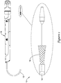
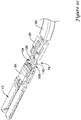
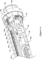
- FIG. 1 is a side view of an example medical device system 10. It should be noted that some features of system 10 are either not shown, or are shown schematically, in Figure 1 for simplicity. Additional details regarding some of the components of system 10 are provided in other figures in greater detail.
- System 10 may be used to deliver and/or deploy a variety of medical devices to a number of locations within the anatomy.
- system 10 is a replacement heart valve delivery system (e.g., a replacement aortic valve delivery system) that can be used for percutaneous delivery of a replacement heart valve. This, however, is not intended to be limiting as system 10 may also be used for other interventions including mitral valve replacement, valve repair, valvuloplasty, and the like, or other similar interventions.
- System 10 may generally be described as a catheter system that includes an outer sheath or catheter 12 and an inner catheter or tube 14 (a portion of which is shown in Figure 1 in phantom line) extending at least partially through outer sheath 12.
- a medical device implant 16 may be coupled to inner catheter 14 and disposed within outer sheath 12 during delivery of implant 16.
- a handle 18 may be disposed at the proximal end of outer sheath 12 and inner catheter 14. In general, handle 18 may be configured to manipulate the position of outer sheath 12 relative to inner catheter 14 as well as aid in the deployment of implant 16.
- system 10 may be advanced percutaneously through the vasculature to a position adjacent to an area of interest.
- system 10 may be advanced through the vasculature to a position adjacent to a defective aortic valve.
- implant 16 may be generally disposed in an elongated and low profile "delivery" configuration within outer sheath 12. Once positioned, outer sheath 12 may be retracted to expose implant 16.
- Implant 16 may be actuated in order to expand implant into a generally shortened and larger profile "deployed" configuration suitable for implantation within the anatomy.
- system 10 can be removed from the vasculature, leaving implant 16 in place to function as, for example, a suitable replacement for the native aortic valve.
- implant 16 may be deployed within the native valve (e.g., the native valve is left in place and not excised). Alternatively, the native valve may be removed and implant 16 may be deployed in its place as a replacement.
- Figures 2-13 illustrate some of the components of system 10.
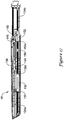
- Figure 2 is a cross-sectional side view of outer sheath 12.
- outer sheath 12 has a proximal portion 20 and a distal portion 22.
- Distal portion 22 may have a slightly enlarged or flared inner diameter, which may provide additional space for holding implant 16 therein.
- the inner diameter of outer sheath 12 along proximal portion 20 may be in the range of about 0.254 to 1.27 cm (0.10 to 0.50 inches), or about 0.508 to 1.016 cm (0.20 to 0.40 inches), or about 0.508 to 0.762 cm (0.20 to 0.30 inches), or about 0.56388 ⁇ 0.0508 cm (0.222 ⁇ 0.002 inches).
- the inner diameter of outer sheath 12 along distal portion 22 may be in the range of about 0.254 to 1.27 cm (0.10 to 0.50 inches), or about 0.508 to 1.016 cm (0.20 to 0.40 inches), or about 0.508 to 0.762 cm (0.20 to 0.30 inches), or about 0.579 to 0.5842 cm (0.228 to 0.230 inches).
- distal tip 24 At the distal end of distal portion 22 may be a distal tip 24, which may be flared or otherwise have a funnel-like shape.
- the funnel-like shape increases the outer diameter (and inner diameter) of outer sheath 12 at distal tip 24 and may aid in the sheathing and/or resheathing of implant 16 into outer sheath 12.
- outer sheath 12 may have a generally constant outer diameter.
- outer sheath 12 may have an outer diameter in the range of about 0.254 to 1.27 cm (0.10 to 0.50 inches), or about 0.508 to 1.016 cm (0.20 to 0.40 inches), or about 0.508 to 0.762 cm (0.20 to 0.30 inches), or about 0.6858 cm (0.270 inches). These are just examples.
- outer sheath 12 may also have a length that is appropriate for reaching the intended area of interest within the anatomy.
- outer sheath 12 may have a length in the range of about 30 to 200 cm, or about 60 to 150 cm, or about 100 to 120 cm, or about 108 ⁇ 0.20 cm.
- Outer sheath 12 may also be curved.
- a distal section of outer sheath 12 may be curved.
- the radius of the curve (measured from the center of outer sheath 12) may be in the range of about 2 to 6 cm (20 to 60 mm), or about 3 to 4 cm (30 to 40 mm), or about 3.675 cm (36.75 mm). Again, these dimensions are examples and are not intended to be limiting.
- Outer sheath 12 may be formed from a singular monolithic tube or unitary member. Alternatively, outer sheath 12 may include a plurality of layers or portions. One or more of these layers may include a reinforcing structure such as a braid, coil, mesh, combinations thereof, or the like.
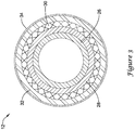
- Figure 3 illustrates one example of a multilayer structure for outer sheath 12.
- outer sheath 12 may include an inner liner or layer 26.
- An intermediate or tier layer 28 may be disposed on inner liner 26.
- a reinforcement 30 may be disposed on intermediate layer 28.
- a topcoat or outer layer 32 may be disposed on reinforcement 30.
- an outer coating 34 (e.g., a lubricious coating, a hydrophilic coating, a hydrophobic coating, etc.) may be disposed along portions or all of topcoat 32.
- outer sheath 12 including embodiments including two or more layers that may be different from those shown in Figure 3 , embodiments without a reinforcement, and the like, or other suitable configurations.
- inner liner 26 may include a polymeric material such as fluorinated ethylene propylene (FEP) and may have a thickness in the range of about 0.00254 to 0.0127 cm (0.001 to 0.005 inches) or about 0.00762 ⁇ 0.00254 (0.003 ⁇ 0.001 inches)
- intermediate layer 28 may include a polymer material such as polyether block amide (e.g., PEBAX 6333) and may have a thickness in the range of about 0.00254 to 0.0127 cm (0.001 to 0.005 inches) or about 0.00508 ⁇ 0.00254 (0.002 ⁇ 0.001 inches)
- outer coating 34 may include a polymer material such as polyether block amide (e.g., PEBAX 7233) and may have a thickness in the range of about 0.00254 to 0.0254 cm (0.001 to 0.01 inches).
- outer coating 34 may vary in thickness. For example, along proximal portion 20 outer coating 34 may have greater thickness, such as about 0.0127 to about 0.0508 cm or about 0.02159 cm (0.005 to 0.02 inches or about 0.0085 inches), than along distal portion 22 and/or distal tip 24, which may be about 0.0127 to about 0.0508 cm or about 0.01651 cm (e.g., about 0.005 to 0.02 inches or about 0.0065 inches). These are just examples as other suitable materials may be used.
- distal tip 24 may also vary.
- inner liner 26 i.e., a 2.5 mm section thereof
- outer sheath 12 e.g., around reinforcement 30 and topcoat 32
- a ring member (not shown) made from a suitable material such as a 55D polyether block amide (e.g., 55D PEBAX) may be disposed over inner liner 26 and heat bonded to form distal tip 24. This may form the funnel-like shape of distal tip 24.
- Reinforcement 30 may also vary in form.
- reinforcement 30 may take the form of a braid, coil, mesh, or the like.
- reinforcement 30 may include a metallic braid (e.g., stainless steel).
- reinforcement 30 may also include additional structures such as one or more longitudinally-extending strands.
- reinforcement 30 may include a pair of longitudinally-extending aramid and/or para aramid strands (for example, KEVLAR®) disposed on opposite sides of the braid. These strands may or may not be woven into portions or all of the braid.
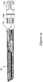
- FIG. 4 is a side view of the inner catheter 14.
- a distal end region of inner catheter 14 may include a step in outer diameter 40 that defines a decreased outer diameter section 42.
- decreased outer diameter section 42 may have an outer diameter in the range of about 0.127 to 0.635 cm (0.05 to 0.25 inches), or about 0.254 to 0.508 cm (0.10 to 0.20 inches), or about 0.38608 ⁇ 0.00762 (0.152 ⁇ 0.003 inches) as opposed to the remainder of inner catheter 14 where the outer diameter may be in the range of about 0.127 to 0.762 cm (0.05 to 0.30 inches), or about 0.254 to 0.635 cm (0.10 to 0.25 inches), or about 0.508 ⁇ 0.0254 cm (0.20 ⁇ 0.01 inches).
- Decreased outer diameter section 42 may define a region where other components of system 10 may be attached. Some additional details regarding these components can be found herein.
- inner catheter 14 may take the form of an extruded polymer tube. Other forms are also contemplated including other polymer tubes, metallic tubes, reinforced tubes, or the like including other suitable materials such as those disclosed herein.
- inner catheter 14 is a singular monolithic or unitary member. In other embodiments, inner catheter 14 may include a plurality of portions or segments that are coupled together. The total length of inner catheter may be in the range of about 60 to 150 cm, or about 80 to 120 cm, or about 100 to 115 cm, or about 112 ⁇ 0.02 cm.
- inner catheter 14 may also be curved, for example adjacent to the distal end thereof.
- inner catheter 14 may have one or more sections with a differing hardness/stiffness (e.g., differing shore durometer).
- inner catheter may have a proximal region 44a and an intermediate region 44b.
- Proximal region 44a may include a generally stiff polymeric material such as a 72D polyether block amide (e.g., 72D PEBAX) and may have a length in the range of about 60 to 150 cm, or about 80 to 120 cm, or about 100 to 115 cm, or about 109.5 ⁇ 0.02 cm.
- Intermediate region 44b may include a 40D polyether block amide (e.g., 40D PEBAX) and may have a length in the range of about 5 to 25 mm, or about 10 to 20 mm, or about 15 ⁇ 0.01 mm.
- Section 42 may also differ from regions 44a/44b and, in some embodiments, may include a 72D polyether block amide (e.g., 72D PEBAX) and may have a length in the range of about 0.5 to 2 cm (5 to 20 mm), or about 0.8 to 1.5 cm (8 to 15 mm), or about 1 ⁇ 0.001 cm (10 ⁇ 0.01 mm). These are just examples.
- Inner catheter 14 may include one or more lumens.
- Figure 5 which is a cross sectional view of inner catheter 14 adjacent to proximal end portion 36
- inner catheter 14 may include a first lumen 46, a second lumen 48, a third lumen 50, and a fourth lumen 52.
- lumens 46/48/50/52 extend along the entire length of inner catheter 14.
- Other embodiments are contemplated, however, where one or more of lumens 46/48/50/52 extend along only a portion of the length of inner catheter 14.
- fourth lumen 52 may stop just short of the distal end of inner catheter 14 and/or be filled in at its distal end to effectively end fourth lumen 52 proximal of the distal end of inner catheter 14, as illustrated in Figure 6 by the absence of fourth lumen 52 adjacent to the distal end of inner catheter 14.
- first lumen 46 Disposed within first lumen 46 may be push-pull rods 84 (not shown in Figure 5 , seen in other figures including Figure 7 ), which are used to expand and/or elongate implant 16 as explained in more detail herein.
- first lumen 46 may be lined with a low friction liner 54 (e.g., a FEP liner).
- second lumen 48 Disposed within second lumen 48 may be a pin release mandrel 92 (not shown in Figure 5 , seen in other figures including Figure 7 ), which is also explained in more detail herein.
- second lumen 48 may be lined with a hypotube liner 56.
- Third lumen 50 may be a guidewire lumen and this lumen may also be lined with a hypotube liner 58.
- Fourth lumen 52 may be used to house a non-stretch wire 60.
- the form of non-stretch wire 60 may vary.
- non-stretch wire 60 may take the form of a stainless steel braid.
- the non-stretch wire 60 may optionally include a pair of longitudinally-extending aramid and/or para aramid strands (for example, KEVLAR®) disposed on opposite sides of the braid.
- non-stretch wire 60 may be embedded within fourth lumen 52.
- non-stretch wire 60 may extend to a position adjacent to distal end portion 38 but not fully to the distal end of inner catheter 14 as illustrated in Figure 6 by the absence of fourth lumen 52 adjacent to the distal end of inner catheter 14.
- a short distal segment of fourth lumen 52 may be filled in with polymer material adjacent to the distal end of inner catheter 14.
- Inner catheter 14 may also include a guidewire tube extension 62 that extends distally from distal end portion 38.
- a nose cone 64 is attached to guidewire tube extension 62.
- Nose cone 64 generally is designed to have an atraumatic shape.
- Nose cone 64 may also include a ridge or ledge 66 that is configured to abut the distal tip 24 of outer sheath 12 during delivery of implant 16.
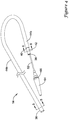
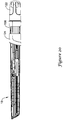
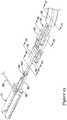
- FIG. 7 illustrates some of the additional components of system 10 and implant 16.
- implant 16 includes a plurality of valve leaflets 68 (e.g., bovine pericardial) which are secured to a cylindrical braid 70 at a post or commissure post 72, for example at the commissure portions of the leaflets 68.
- implant 16 includes three leaflets 68 secured to braid 70 with three posts 72.
- Leaflets 68 may also be secured to the base or "distal end" of braid 70.
- the posts 72 in turn, may be secured to braid 70 (e.g., along the interior of braid 70) with sutures or other suitable mechanisms.
- buckles 76 Positioned adjacent to (e.g., longitudinally spaced from and aligned with) posts 72 are a plurality of buckles 76, which may also be sutured to braid 70 (e.g., along the interior of braid 70).
- one buckle 76 is attached to braid 70 adjacent to each of the three posts 72.
- braid 70 has a total of three buckles 76 and three posts 72 attached thereto.
- a seal 74 (shown in cross-section) may be disposed about braid 70 and, as the name suggests, may help to seal implant 16 within a target implant site or area of interest.
- Coupler 78 may generally include a cylindrical base (not shown) that is attached to inner catheter 14 (e.g., disposed about and attached to reduced outer diameter section 42). Projecting distally from the base are three fingers that are each configured to engage with implant 16 at posts 72 and buckles 76. A collar 80 may further assist in holding together these structures.
- a guide 82 may be disposed over each of the fingers and may serve to keep the fingers of coupler 78 associated with push-pull rods 84 extending adjacent to coupler 78.
- a pin release assembly 86 may be a linking structure that keeps posts 72, buckles 76, and push-pull rods 84 associated with one another.
- Pin release assembly 86 includes a plurality of individual pins 88 that may be joined together via a coiled connection 90 and held to a pin release mandrel 92 with a ferrule 94.
- implant 16 is secured at the distal end of inner catheter 14 by virtue of the association of the fingers of coupler 78 being coupled with a projecting proximal end of buckles 76 (and being held in place with collar 80 disposed over the connection) and by virtue of pins 88 securing together push-pull rods 84 and posts 72.
- outer sheath 12 may be withdrawn (e.g., moved proximally relative to inner catheter 14) to expose implant 16.
- push-pull rods 84 can be used to expand and "lock" implant 16 in the expanded or deployed configuration by proximally retracting push-pull rods 84 to pull posts 72 into engagement with buckles.
- pins 88 can be removed, thereby uncoupling push-pull rods 84 from posts 72, which allows implant 16 to be released from system 10 and deployed in the anatomy.
- FIGs 8-11 illustrate the locking system utilized with system 10.
- push-pull rod 84 extends through guide 82 adjacent to the fingers of coupler 78, through collar 80, through buckle 76, and into a hollow t-shaped bar portion 96 of post 72.
- the distal end of push-pull rod 84 may include an opening or aperture (not shown) that can be aligned with an opening 98 of t-shaped bar portion 96.
- pin 88 When so aligned, pin 88 can be looped through opening 98 and the opening of push-pull rod 84. This secures push-pull rod 84 to post 72 and forms a configuration of these structures that can be utilized during delivery of implant 16.
- the proximal end of post 72 and the distal end of buckle 76 are longitudinally separated and, accordingly, implant 16 is in an elongated and generally low-profile configuration suitable for delivery.
- a clinician can proximally retract push-pull rod 84, thereby moving the proximal ends of posts 72 toward the distal ends of buckles 76 in order to expand implant 16.
- push-pull rod 84 can be retracted sufficiently far enough to lock post 72 with buckle 76 so as to lock implant in an expanded configuration suitable for implantation within the anatomy.
- Figure 9 illustrates push-pull rod 84 proximally retracted. In doing so, post 72 is brought into contact with buckle 76. More particularly, a raised, generally transversely-oriented ridge 100 on t-shaped bar portion 96 may be pulled proximally past buckle 76 so that post 72 is secured and held in place by buckle 76.
- push-pull rods 84 distally to "unlock" implant 16, thereby allowing for repositioning and/or retraction.
- pins 88 may be pulled (e.g., removed from openings 98 and the openings in push-pull rods 84) to uncouple push-pull rods 84 from posts 72 as shown in Figure 10 . Further retraction of push-pull rods 84 causes a longitudinally-oriented ridge 102 on push-pull rods 84 to engage collar 80 and causes collar 80 to slide proximally along the fingers of coupler 78.
- a forked end 104 of the fingers which has a groove 106 formed therein, is exposed and can be uncoupled from a rail 108, which has a projection 110 formed thereon that is configured to mate with groove 106, as shown in Figure 11 .
- system 10 can be removed from the anatomy, leaving behind the expanded and deployed implant 16.
- Figures 12-13 illustrate another component that may be included with system 10.
- Figure 12 is a side view of a portion of a sheathing aid 112.
- sheathing aid 112 includes a base 114 and a group of petals including a set of three longer petals 116 and a pair of shorter petals 118.
- a group of petals 116/118 may be positioned between each of the fingers of coupler 78.
- the coupler 78 may have a total of three fingers
- sheathing aid 112 may have a total of fifteen petals (e.g., three groups that each include three "long" petals 116 and two "short” petals 118, with each group being positioned between adjacent pairs of fingers of coupler 78).
- Base 114 may be secured to inner catheter 14 adjacent to coupler 78 (e.g., underneath coupler 78 and between coupler 78 and inner catheter 14).
- Sheathing aid 112 may be used to aid in the sheathing of implant 16 into outer sheath 12.
- sheathing aid 112 may aid in the initial sheathing of implant 16 (e.g., removing implant 16 from a packaging container such as a bottle and pulling implant 16 into outer sheath 12) and in re-sheathing implant 16 during repositioning and/or retraction of implant 16 within the area of interest.
- Sheathing may be accomplished via the arrangement and positioning of the various petals 116/118.
- Figure 13 illustrates the longer petals 116 woven in and out of braid 70, and the shorter petals 118 disposed along the exterior of braid 70 acting as a funnel for sheathing.
- Figure 14 is a side view of handle 18.
- handle 18 includes a handle housing 120.
- a rotatable control knob 122 may be disposed about handle housing 120 (e.g., at a proximal end of handle housing 120) and may be used to move one or more of the components of system 10 (e.g., outer sheath 12, push-pull rods 84, etc.).
- a rotatable collar 156 may be disposed about the handle housing 120.
- Control knob 122 may be disposed about a proximal portion of collar 156.
- a slidable door 124 may also be disposed about handle housing 120.
- Door 124 may translate distally to expose a distal portion of rotatable collar 156 (not shown in Figure 14 , can be seen in other figures including Figures 19-20 ) positioned generally under door 124.
- Collar 156 may be rotated to move one or more components of system 10 (e.g., push-pull rods 84, pin release mandrel 92, etc.).
- Handle 18 may also include one or more apertures 129a/129b and/or flush ports 126/128 that can be used to flush system 10.
- distal flush port 126 and proximal flush port 128 may be accessible from the exterior of the handle housing 120 through distal aperture 129a and proximal aperture 129b, respectively.
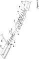
- FIG 15 is a side view of handle 18 with a portion of handle housing 120 removed, exposing at least some of the interior components.
- outer sheath 12 may be attached to a sheath adapter 130.
- Sheath adapter 130 is attached to a sheath carriage 132, which may be threaded onto a lead screw 134.
- Distal flush port 126 may be disposed on sheath adapter 130.
- distal flush port 126 provides access to the interior or lumen of outer sheath 12 (e.g., access to space between inner catheter 14 and outer sheath 12) so that a clinician can flush fluid through the lumen of outer sheath 12 to remove any unwanted materials (e.g., air, fluid, contaminants, etc.) therein prior to use of system 10.
- distal flush port 126 has a luer type connector (e.g., a one-way luer connector) that allows a device such as a syringe with a corresponding connector to be attached thereto for flushing.
- inner catheter 14 Extending through and proximally from sheath adapter 130 is inner catheter 14. A proximal end of inner catheter 14 is attached (e.g., fixedly attached) to an interior body or diverter 136. Diverter 136 is attached to a support body 140. In general, diverter 136 and/or support body 140 may have one or more passageways or lumens formed therein. In some embodiments, push-pull rods 84 and/or pin release mandrel 92 may extend through respective passageways.
- first shaft or hypotube 142 and a second shaft or hypotube 144 may extend through the passageways in diverter 136, and in some embodiments, the first shaft or hypotube 142 extends through a first passageway and the second shaft or hypotube 144 extends through a second passageway that is separate or distinct from the first passageway.
- first shaft 142 is attached to pin release mandrel 92.
- second shaft 144 is attached to push-pull rods 84.
- three push-pull rods 84 are utilized.
- the three push-pull rods 84 come together (e.g., brought into contact with one another or otherwise brought into relatively close proximity with one another) adjacent to the distal end of inner catheter 14 and enter first lumen 46.
- push-pull rods 84 may be attached to one another.
- push-pull rods 84 may be welded together about 10.16 cm (about 4.00 inches) from their distal ends.
- push-pull rods 84 may be welded together proximate their proximal ends in addition to or instead of the distal weld. Proximally thereafter, push-pull rods 84 may extend to second shaft 144.
- a hypotube (e.g., hypotube liner 58 disposed along guidewire lumen 52) may extend through diverter 136 within a passageway therein and then be "diverted” around a portion of diverter 136 and support body 140, and ultimately be extended to a position at the proximal end of handle 18 so as to provide a user access to guidewire lumen 52.
- Proximal flush port 128 may be disposed on support body 140 that can be used to flush the lumens of inner catheter 14 and, for example, may function similarly to distal flush port 126.
- first shaft 142 may be secured to a slider 146 and second shaft 144 may be secured to a force limiter body 150.
- the connections between the various components may include a number of different types of connections including mechanical bonding (e.g., pinning, threading, interference fit, etc.), adhesive bonding, thermal bonding, etc.
- Slider 146 may be slidable relative to force limiter body 150. In some embodiments, slider 146 may be selectively locked to force limiter body 150, thereby preventing relative movement between the slider 146 and the force limiter body 150.
- Force limiter body 150 may be secured to a push-pull rod carriage 152, which may be threaded onto lead screw 134. Thus, movement of lead screw 134 can cause movement of push-pull rod carriage 152 and force limiter body 150 and thus, push-pull rods 84 (via second shaft 144).
- force limiter body 150 forms or defines a stop point that provides tactile feedback (e.g., resistance to further rotation of control knob 122) to the user indicating that push-pull rods 84 have been retracted proximally a sufficient distance to lock posts 72 with buckles 76.
- tactile feedback e.g., resistance to further rotation of control knob 122
- a chock 148 may be positioned adjacent to slider 146 to selectively lock slider 146 to force limiter body 150. In order to allow pin release mandrel 92 to be proximally retracted to pull pins 88, chock 148 can be rotated or otherwise moved to a secondary position or configuration.
- chock 148 no longer forms a barrier to further movement of, for example, slider 146 and pin release mandrel 92. Accordingly, with chock 148 no longer acting as an impediment, slider 146 and pin release mandrel 92 can be proximally retracted to facilitate deployment of implant 16 by allowing pins 88 to be pulled.
- Handle 18 also includes a rotatable ring 155 with internal teeth that are configured to engage with teeth on a gear 157 coupled to lead screw 134.
- Ring 155 is coupled to control knob 122 so that rotation of control knob 122 results in analogous motion of ring 155 and thus lead screw 134.
- Handle 18 is generally configured for coordinated movement of multiple structures of system 10.
- handle 18 is configured to allow a user to move outer sheath 12 (e.g., relative to inner catheter 14), move push-pull rods 84, and move pin release mandrel 92.
- handle 18 is configured so that the appropriate structure can be moved at the appropriate time during the intervention so that implant 16 can be delivered in an efficient manner.
- Some examples of how the coordinated movement of system 10 may occur within handle 18 may be similar to those disclosed in U.S. Patent Application Pub. No. US 2010/0280495 .
- handle 18 may include a lost motion barrel 158.
- Lost motion barrel 158 is configured to engage carriages 132/152 and/or screws associated with carriages 132/152 at different times during the intervention to stop motion (e.g., create "lost motion" of the appropriate carriage).
- Figures 16-19 illustrate some of the coordinated motion achieved by handle 18. It should be noted that some elements of system 10 are not shown in Figures 16-20 for clarity.
- Figure 16 illustrates a first position or state for handle 18 where outer sheath 12 is extended distally relative to inner catheter 14 (and handle 18) so as to fully sheath (e.g., contain) implant 16. While in this position, sheath carriage 132 is positioned adjacent to the distal end of handle 18.
- a rod screw 152a associated with push-pull rod carriage 152 is extended distally from push-pull rod carriage 152 and positioned within lost motion barrel 158.
- lead screw 134 Upon rotation of control knob 122 (e.g., in the clockwise direction), lead screw 134 begins to rotate. Rotation of lead screw 134 causes sheath carriage 132 to move along lead screw 134 in the proximal direction, resulting in proximal movement of outer sheath 12 (e.g., "unsheathing" implant 16). This initial rotation of lead screw 134 also causes rod screw 152a to rotate.
- rod screw 152a may be engaged with a helical thread disposed along the interior of lost motion barrel 158.
- rod screw 152a is spaced from push-pull rod carriage 152, it does not exert a force onto push-pull rod carriage 152.
- initial motion of control knob 122 does not result in movement of push-pull rod carriage 152 and, instead, only results in translation of sheath carriage 132 and rotation (and translation) of rod screw 152a.
- rod screw 152a (e.g., the knob formed therein) reaches an essentially linear thread or pathway formed at the end of lost motion barrel 158.
- the linear thread allows rod screw 152a to translate along lead screw 134 to a position where rod screw 152a contacts (e.g., is threaded within and abuts) push-pull rod carriage 152. In doing so, rod screw 152a can contact and move proximally push-pull carriage 152. Accordingly, further rotation of lead screw 134 not only causes sheath carriage 132 to move proximally but also causes push-pull rod carriage 152 to move proximally as shown in Figure 17 .
- a sheath carriage screw 132a of sheath carriage 132 enters lost motion barrel 158 as shown in Figure 18 .
- This may occur in a manner similar to how rod screw 152a threads and unthreads with the helical thread formed along lost motion barrel 158.
- sheath carriage screw 132a may follow an essentially linear thread or pathway formed along or adjacent to lost motion barrel 158.
- sheath carriage screw 132a e.g., a knob or projection formed thereon
- sheath carriage screw 132a may shift into engagement with the helical thread within lost motion barrel 158 and rotate.
- This rotation "unthreads" sheath carriage screw 132a from sheath carriage 132. Accordingly, additional rotation of lead screw 134 results in continued proximal movement of push-pull rod carriage 152 while motion of sheath carriage 132 ceases.
- lead screw 134 has a plurality of portions, for example a first portion 134a and a second portion 134b, with a differing pitch to its thread. This may allow carriages 132/152 to travel at different rates along lead screw 134.
- the pitch of lead screw 134 along which sheath carriage 132 translates may be generally more spaced or slanted than at positions adjacent to push-pull rod carriage 152.
- the coordinated movement of carriages 132/152 also may be configured so that sheath carriage 132 translates along lead screw 134 at a greater rate than push-pull rod carriage 152.
- Other configurations are contemplated where the above-mentioned configuration is reversed as well as further configurations where the pitch of lead screw 134 is essentially constant or includes a number of different pitch regions.
- door 124 may be slid distally along a collar 156 (which is positioned on handle 18) as shown in Figure 19 .
- Push-pull rod carriage 152 may also include a radially-extending proximal flag member 164.
- flag member 164 may be designed as a feature that can prevent collar 156 from being rotated earlier than desired (and, thus, prevent pins 88 from being pulled earlier than desired).
- flag member 164 may be positioned within and follow a groove (not shown) along the interior of collar 156.
- flag member 164 While positioned within the groove, flag member 164 essentially forms a physical barrier that prevents collar 156 from rotating relative to handle housing 120.
- push-pull rod carriage 152 is translated proximally to the back of handle housing 120 (e.g., when push-pull rods 84 are proximally retracted so as to lock posts 72 with buckles 76)
- flag member 164 exits the groove in collar 156. Accordingly, flag member 164 no longer impedes rotation of collar 156 and, as such, collar 156 can now be rotated to pull pins 88.
- Collar 156 via ring 154, is associated with a gear 160 engaged with a secondary screw 162. Notches at a proximal end of collar 156 engage protrusions on ring 154 such that rotation of collar 156 causes corresponding rotation of ring 154 and thus secondary screw 162.
- chock 148 The initial rotation of collar 156 is sufficient to rotate chock 148 (e.g., via a mechanical interaction between collar 156 and chock 148 that causes chock 148 to shift) from a first configuration where slider 146 (and, thus, pin release mandrel 92) is selectively locked to force limiter body 150, to a secondary configuration, which permits slider 146 to translate along secondary screw 162 as secondary screw 162 rotates, to proximally retract and pull pins 88 (e.g., via pin release mandrel 92).
- chock 148 in the first configuration engages a ridge 168 along a top portion of force limiter body 150 which forms a physical barrier that prevents proximal translation of slider 146 relative to force limiter body 150.
- slider 146 can translate proximally within a groove 166 disposed in the top portion of force limiter body 150 (e.g., as seen in Figure 22 ), as collar 156 is rotated about the handle housing 120 to pull the pins 88 from the openings 98 and the openings in the distal ends of the push-pull rods 84. Once pins 88 have been removed, push-pull rods 84 may be withdrawn from implant 16, thereby deploying the implant at the target site (area of interest).
- control knob 122 may be rotated to move the sheath carriage 132 distally within the handle housing 120, thereby moving outer sheath 12 distally relative to inner catheter 14 and three-finger coupler 78 so as to cover or re-sheath the elements of system 10 disposed at the distal end. System 10 may then be removed from the patient's anatomy.
- shifting implant 16 from a first or elongated configuration to a second or expanded configuration involves the proximal retraction of push-pull rods 84 so that posts 72 move proximally so as to engage and lock with buckles 76.
- ridges 100 on posts 72 engage and lock with buckle 76.
- ridges 100 may need to be properly aligned or oriented (e.g., face the "correct" direction) so as to engage buckles 76. If ridges 100 do not engage buckles 76 while in the proper orientation, posts 72 may not lock with buckles 76 and implant 16 may not lock properly.
- post 72 may still be able to be seated within buckle 76, but ridge 100 would be oriented in an improper direction so that the post 72 could disassociate from buckle 76 and implant 16 may not properly remain in the expanded configuration.
- posts 72 may still be capable of passing into buckles 76 even when twisted, a clinician may believe under fluoroscopic visualization that implant 16 is locked when, in reality, one or more of ridges 100 may not be properly positioned within buckle 76 to effect proper locking of implant 16. Accordingly, a clinician may pull pins 88 believing that implant 16 is properly locked in the expanded configuration only to find out later that implant 16 is actually is not properly locked.
- device 10 includes one or more features and/or structures that help maintain the proper alignment of posts 72 with buckles 76 so that locking integrity of implant 16 can be enhanced.
- these features are aimed at maintaining proper alignment of posts 72 with buckles 76 and at reducing twisting of posts 72 and/or push-pull rods 84.
- push-pull rods 84 have at least a region where the outer surface thereof has a non-circular cross-sectional shape that is configured to engage with or "mate" with one or more of the structures associated with locking implant 16 (e.g., the "locking assembly", which may include buckle 76, collar 80, guide 82, inner catheter 14, and/or other structures of device 10).
- push-pull rod 84 may have a rectangular cross-sectional shape.
- Figure 25 illustrates that an interior passageway 180 of buckle 76 (e.g., where push-pull rod 84 may extend through) may have a shape corresponding to shape of push-pull rod 84.
- at least a portion of the shape of passageway 180 corresponds to or otherwise resembles the rectangular shape of push-pull rod 84. This may allow push-pull rod to "key” or otherwise have a "lock and key” structural relationship with passageway 180. Accordingly, passageway 180 may prevent or otherwise limit any rotation of push-pull rod 84.
- passageway 180 may also help to direct push-pull rod 84 therein and help to "correct” any rotation that may be present in push-pull rod 84.
- FIG. 26 illustrates that an interior passageway 182 of collar 80 may have a shape corresponding to shape of push-pull rod 84.
- Figure 27 illustrates guide 82 that may include similar features.
- guide 82 may include a first lumen 184 that is disposed about a finger 186 of coupler 78.
- Guide 82 may also include a second lumen 188 that may have a shape corresponding to shape of push-pull rod 84.
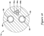
- Figure 28 illustrates a cross-sectional view of inner catheter 14.
- first lumen 46 may have a non-circular cross-sectional shape.
- first lumen 46 may have a triangular cross-sectional shape.
- the three push-pull rods 84a/84b/84c (which, in this example are shown having a circular cross-sectional shape) extending therethrough may be confined within lumen 46 so that rotation of push-pull rods 84a/84b/84c relative to inner catheter 14 may be reduced if not altogether eliminated.
- inner catheter 14 may also be utilized to help maintain proper alignment of push-pull rod 84 so that implant 16 may be properly locked.
- Figures 29-31 illustrate some of the additional cross-sectional shapes contemplated for push-pull rod 84.
- Figure 29 illustrates push-pull rod 84' having a semi-circular or "D" cross-sectional shape.
- Figure 30 illustrates push-pull rod 84" having a hexagonal cross-sectional shape.
- Figure 31 illustrates push-pull rod 84" having a triangular cross-sectional shape.
- These are just examples as numerous other shapes are also contemplated including, for example, oval, semi-oval, polygonal, etc.
- the non-circular cross-sectional shape may be present along only a portion of the length of push-pull rods 84 or along substantially the entire length.
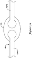
- Figure 32 illustrates a key member 190 that may be disposed about a portion of push-pull rod 84.
- key member 190 may be attached to buckle 76 (e.g., along a distal surface of buckle 76).
- this is not intended to be limiting as key member 190 may be positioned at other locations, as desired, along system 10.
- key member 190 may have an internal passageway 192, similar to other internal passageways disclosed herein, that may have a shape corresponding to shape of push-pull rod 84.
- keyed relationship between push-pull rods 84 and key member 190 may help to reduce rotation of push-pull rods 84 and/or otherwise help maintain proper alignment of posts 72 with buckles 76.
- FIG 33 illustrates another example push-pull rod 194 that may be similar to other push-pull rods disclosed herein.
- Push-pull rod 194 may include a first portion 194a and a second portion 194b that are joined together with a swivel body 196.
- the structural arrangement of push-pull rod 194 may form a "swivel" that allows portions of push-pull rod 194 to rotate. In the event that one of portions 194a/194b becomes rotated, the swivel may stop this rotation from being translated along the full length of push-pull rod 194.
- the swivel may help reduce the possibility that this twisting is transmitted further distally where it might otherwise cause twisting of post 72.
- the swivel e.g., swivel body 196
- the swivel may be positioned adjacent to post 72 so that rotation of post 72 can be reduced.
- other locations may also be utilized.
- the materials that can be used for the various components of system 10 (and/or other systems disclosed herein) and the various tubular members disclosed herein may include those commonly associated with medical devices.
- outer sheath 12 and/or inner catheter 14 are commonly associated with medical devices.
- this is not intended to limit the devices and methods described herein, as the discussion may be applied to other similar tubular members and/or components of tubular members or devices disclosed herein.
- Outer sheath 12 and/or inner catheter 14 may be made from a metal, metal alloy, polymer (some examples of which are disclosed below), a metal-polymer composite, ceramics, combinations thereof, and the like, or other suitable material.
- suitable metals and metal alloys include stainless steel, such as 304V, 304L, and 316LV stainless steel; mild steel; nickel-titanium alloy such as linear-elastic and/or super-elastic nitinol; other nickel alloys such as nickel-chromium-molybdenum alloys (e.g., UNS: N06625 such as INCONEL® 625, UNS: N06022 such as HASTELLOY® C-22®, UNS: N10276 such as HASTELLOY® C276®, other HASTELLOY® alloys, and the like), nickel-copper alloys (e.g., UNS: N04400 such as MONEL® 400, NICKEL VAC® 400, NICORROS® 400
- Linear elastic and/or non-super-elastic nitinol may be distinguished from super elastic nitinol in that the linear elastic and/or non-super-elastic nitinol does not display a substantial "superelastic plateau” or “flag region” in its stress/strain curve like super elastic nitinol does.
- linear elastic and/or non-super-elastic nitinol as recoverable strain increases, the stress continues to increase in a substantially linear, or a somewhat, but not necessarily entirely linear relationship until plastic deformation begins or at least in a relationship that is more linear that the super elastic plateau and/or flag region that may be seen with super elastic nitinol.
- linear elastic and/or non-super-elastic nitinol may also be termed "substantially" linear elastic and/or non-super-elastic nitinol.
- linear elastic and/or non-super-elastic nitinol may also be distinguishable from super elastic nitinol in that linear elastic and/or non-super-elastic nitinol may accept up to about 2-5% strain while remaining substantially elastic (e.g., before plastically deforming) whereas super elastic nitinol may accept up to about 8% strain before plastically deforming. Both of these materials can be distinguished from other linear elastic materials such as stainless steel (that can also can be distinguished based on its composition), which may accept only about 0.2 to 0.44 percent strain before plastically deforming.
- the linear elastic and/or non-super-elastic nickel-titanium alloy is an alloy that does not show any martensite/austenite phase changes that are detectable by differential scanning calorimetry (DSC) and dynamic metal thermal analysis (DMTA) analysis over a large temperature range.
- DSC differential scanning calorimetry
- DMTA dynamic metal thermal analysis
- the mechanical bending properties of such material may therefore be generally inert to the effect of temperature over this very broad range of temperature.
- the mechanical bending properties of the linear elastic and/or non-super-elastic nickel-titanium alloy at ambient or room temperature are substantially the same as the mechanical properties at body temperature, for example, in that they do not display a super-elastic plateau and/or flag region.
- the linear elastic and/or non-super-elastic nickel-titanium alloy maintains its linear elastic and/or non-super-elastic characteristics and/or properties.
- the linear elastic and/or non-super-elastic nickel-titanium alloy may be in the range of about 50 to about 60 weight percent nickel, with the remainder being essentially titanium. In some embodiments, the composition is in the range of about 54 to about 57 weight percent nickel.
- a suitable nickel-titanium alloy is FHP-NT alloy commercially available from Furukawa Techno Material Co. of Kanagawa, Japan. Some examples of nickel titanium alloys are disclosed in U.S. Patent Nos. 5,238,004 and 6,508,803 . Other suitable materials may include ULTANIUMTM (available from Neo-Metrics) and GUM METALTM (available from Toyota).
- a superelastic alloy for example a superelastic nitinol can be used to achieve desired properties.
- portions or all of outer sheath 12 and inner catheter 14 may also be doped with, made of, or otherwise include a radiopaque material.
- Radiopaque materials are understood to be materials capable of producing a relatively bright image on a fluoroscopy screen or another imaging technique during a medical procedure. This relatively bright image aids the user of system 10 in determining its location.
- Some examples of radiopaque materials can include, but are not limited to, gold, platinum, palladium, tantalum, tungsten alloy, polymer material loaded with a radiopaque filler, and the like. Additionally, other radiopaque marker bands and/or coils may also be incorporated into the design of system 10 to achieve the same result.
- outer sheath 12 and inner catheter 14, or portions thereof may be made of a material that does not substantially distort the image and create substantial artifacts (i.e., gaps in the image). Certain ferromagnetic materials, for example, may not be suitable because they may create artifacts in an MRI image. Outer sheath 12 and inner catheter 14, or portions thereof, may also be made from a material that the MRI machine can image.
- MRI Magnetic Resonance Imaging
- Some materials that exhibit these characteristics include, for example, tungsten, cobalt-chromium-molybdenum alloys (e.g., UNS: R30003 such as ELGILOY®, PHYNOX®, and the like), nickel-cobalt-chromium-molybdenum alloys (e.g., UNS: R30035 such as MP35-N® and the like), nitinol, and the like, and others.
- cobalt-chromium-molybdenum alloys e.g., UNS: R30003 such as ELGILOY®, PHYNOX®, and the like
- nickel-cobalt-chromium-molybdenum alloys e.g., UNS: R30035 such as MP35-N® and the like
- nitinol and the like, and others.
- a sheath or covering may be disposed over portions or all of outer sheath 12 and inner catheter 14 that may define a generally smooth outer surface for system 10. In other embodiments, however, such a sheath or covering may be absent from a portion of all of system 10, such that outer sheath 12 and inner catheter 14 may form an outer surface.
- the sheath may be made from a polymer or other suitable material.
- suitable polymers may include polytetrafluoroethylene (PTFE), ethylene tetrafluoroethylene (ETFE), fluorinated ethylene propylene (FEP), polyoxymethylene (POM, for example, DELRIN® available from DuPont), polyether block ester, polyurethane (for example, Polyurethane 85A), polypropylene (PP), polyvinylchloride (PVC), polyether-ester (for example, ARNITEL® available from DSM Engineering Plastics), ether or ester based copolymers (for example, butylene/poly(alkylene ether) phthalate and/or other polyester elastomers such as HYTREL® available from DuPont), polyamide (for example, DURETHAN® available from Bayer or CRISTAMID® available from Elf Atochem), elastomeric polyamides, block polyamide/ethers, polyether block amide (PEBA, for example available under the trade name PEBAX®), ethylene vinyl acetate
- the exterior surface of the system 10 may be sandblasted, beadblasted, sodium bicarbonate-blasted, electropolished, etc.
- a coating for example a lubricious, a hydrophilic, a protective, or other type of coating may be applied over portions or all of the sheath, or in embodiments without a sheath over portion of outer sheath 12 and inner catheter 14, or other portions of system 10.
- the sheath may comprise a lubricious, hydrophilic, protective, or other type of coating.
- Hydrophobic coatings such as fluoropolymers provide a dry lubricity which improves device handling and device exchanges.
- Lubricious coatings improve steerability and improve lesion crossing capability.
- Suitable lubricious polymers are well known in the art and may include silicone and the like, hydrophilic polymers such as high-density polyethylene (HDPE), polytetrafluoroethylene (PTFE), polyarylene oxides, polyvinylpyrolidones, polyvinylalcohols, hydroxy alkyl cellulosics, algins, saccharides, caprolactones, and the like, and mixtures and combinations thereof.
- HDPE high-density polyethylene
- PTFE polytetrafluoroethylene
- polyarylene oxides polyvinylpyrolidones
- polyvinylalcohols polyvinylalcohols
- hydroxy alkyl cellulosics algins
- Hydrophilic polymers may be blended among themselves or with formulated amounts of water insoluble compounds (including some polymers) to yield coatings with suitable lubricity, bonding, and solubility.
- Some other examples of such coatings and materials and methods used to create such coatings can be found in U.S. Patent Nos. 6,139,510 and 5,772,609 .
- the coating and/or sheath may be formed, for example, by coating, extrusion, co-extrusion, interrupted layer co-extrusion (ILC), or fusing several segments end-to-end.
- the layer may have a uniform stiffness or a gradual reduction in stiffness from the proximal end to the distal end thereof. The gradual reduction in stiffness may be continuous as by ILC or may be stepped as by fusing together separate extruded tubular segments.
- the outer layer may be impregnated with a radiopaque filler material to facilitate radiographic visualization. Those skilled in the art will recognize that these materials can vary widely without deviating from the scope of the present invention.
Applications Claiming Priority (2)
| Application Number | Priority Date | Filing Date | Title |
|---|---|---|---|
| US201161559931P | 2011-11-15 | 2011-11-15 | |
| PCT/US2012/065076 WO2013074671A1 (en) | 2011-11-15 | 2012-11-14 | Medical device with keyed locking structures |
Publications (2)
| Publication Number | Publication Date |
|---|---|
| EP2779945A1 EP2779945A1 (en) | 2014-09-24 |
| EP2779945B1 true EP2779945B1 (en) | 2021-07-14 |
Family
ID=48281321
Family Applications (1)
| Application Number | Title | Priority Date | Filing Date |
|---|---|---|---|
| EP12794602.8A Active EP2779945B1 (en) | 2011-11-15 | 2012-11-14 | Medical device with keyed locking structures |
Country Status (6)
| Country | Link |
|---|---|
| US (1) | US20130123796A1 (ja) |
| EP (1) | EP2779945B1 (ja) |
| JP (1) | JP2015501680A (ja) |
| CN (1) | CN104039272A (ja) |
| CA (1) | CA2855936C (ja) |
| WO (1) | WO2013074671A1 (ja) |
Families Citing this family (80)
| Publication number | Priority date | Publication date | Assignee | Title |
|---|---|---|---|---|
| CN1447669A (zh) | 2000-08-18 | 2003-10-08 | 阿特里泰克公司 | 用于过滤从心房附件流出的血液的可膨胀植入装置 |
| US7780725B2 (en) | 2004-06-16 | 2010-08-24 | Sadra Medical, Inc. | Everting heart valve |
| US8052749B2 (en) | 2003-12-23 | 2011-11-08 | Sadra Medical, Inc. | Methods and apparatus for endovascular heart valve replacement comprising tissue grasping elements |
| US11278398B2 (en) | 2003-12-23 | 2022-03-22 | Boston Scientific Scimed, Inc. | Methods and apparatus for endovascular heart valve replacement comprising tissue grasping elements |
| US7988724B2 (en) | 2003-12-23 | 2011-08-02 | Sadra Medical, Inc. | Systems and methods for delivering a medical implant |
| US8343213B2 (en) | 2003-12-23 | 2013-01-01 | Sadra Medical, Inc. | Leaflet engagement elements and methods for use thereof |
| US7381219B2 (en) | 2003-12-23 | 2008-06-03 | Sadra Medical, Inc. | Low profile heart valve and delivery system |
| US7959666B2 (en) * | 2003-12-23 | 2011-06-14 | Sadra Medical, Inc. | Methods and apparatus for endovascularly replacing a heart valve |
| US8579962B2 (en) | 2003-12-23 | 2013-11-12 | Sadra Medical, Inc. | Methods and apparatus for performing valvuloplasty |
| US8840663B2 (en) | 2003-12-23 | 2014-09-23 | Sadra Medical, Inc. | Repositionable heart valve method |
| US20050137687A1 (en) | 2003-12-23 | 2005-06-23 | Sadra Medical | Heart valve anchor and method |
| US20120041550A1 (en) | 2003-12-23 | 2012-02-16 | Sadra Medical, Inc. | Methods and Apparatus for Endovascular Heart Valve Replacement Comprising Tissue Grasping Elements |
| DE102005003632A1 (de) | 2005-01-20 | 2006-08-17 | Fraunhofer-Gesellschaft zur Förderung der angewandten Forschung e.V. | Katheter für die transvaskuläre Implantation von Herzklappenprothesen |
| US7569071B2 (en) | 2005-09-21 | 2009-08-04 | Boston Scientific Scimed, Inc. | Venous valve, system, and method with sinus pocket |
| US20070213813A1 (en) | 2005-12-22 | 2007-09-13 | Symetis Sa | Stent-valves for valve replacement and associated methods and systems for surgery |
| US7896915B2 (en) | 2007-04-13 | 2011-03-01 | Jenavalve Technology, Inc. | Medical device for treating a heart valve insufficiency |
| ES2903231T3 (es) | 2008-02-26 | 2022-03-31 | Jenavalve Tech Inc | Stent para el posicionamiento y anclaje de una prótesis valvular en un sitio de implantación en el corazón de un paciente |
| US9044318B2 (en) | 2008-02-26 | 2015-06-02 | Jenavalve Technology Gmbh | Stent for the positioning and anchoring of a valvular prosthesis |
| CN102245256B (zh) | 2008-10-10 | 2014-07-23 | 萨德拉医学公司 | 医疗装置以及用于输送医疗装置的输送系统 |
| US8579964B2 (en) | 2010-05-05 | 2013-11-12 | Neovasc Inc. | Transcatheter mitral valve prosthesis |
| CN103002833B (zh) | 2010-05-25 | 2016-05-11 | 耶拿阀门科技公司 | 人工心脏瓣及包括人工心脏瓣和支架的经导管输送的内假体 |
| EP2613737B2 (en) | 2010-09-10 | 2023-03-15 | Symetis SA | Valve replacement devices, delivery device for a valve replacement device and method of production of a valve replacement device |
| US9308087B2 (en) | 2011-04-28 | 2016-04-12 | Neovasc Tiara Inc. | Sequentially deployed transcatheter mitral valve prosthesis |
| US9554897B2 (en) | 2011-04-28 | 2017-01-31 | Neovasc Tiara Inc. | Methods and apparatus for engaging a valve prosthesis with tissue |
| EP2520251A1 (en) | 2011-05-05 | 2012-11-07 | Symetis SA | Method and Apparatus for Compressing Stent-Valves |
| US9510945B2 (en) * | 2011-12-20 | 2016-12-06 | Boston Scientific Scimed Inc. | Medical device handle |
| US9345573B2 (en) | 2012-05-30 | 2016-05-24 | Neovasc Tiara Inc. | Methods and apparatus for loading a prosthesis onto a delivery system |
| US9883941B2 (en) | 2012-06-19 | 2018-02-06 | Boston Scientific Scimed, Inc. | Replacement heart valve |
| US9681951B2 (en) | 2013-03-14 | 2017-06-20 | Edwards Lifesciences Cardiaq Llc | Prosthesis with outer skirt and anchors |
| US9572665B2 (en) | 2013-04-04 | 2017-02-21 | Neovasc Tiara Inc. | Methods and apparatus for delivering a prosthetic valve to a beating heart |
| JP6563394B2 (ja) | 2013-08-30 | 2019-08-21 | イェーナヴァルヴ テクノロジー インコーポレイテッド | 人工弁のための径方向に折り畳み自在のフレーム及び当該フレームを製造するための方法 |
| US20160067040A1 (en) | 2014-09-09 | 2016-03-10 | Boston Scientific Scimed, Inc. | Valve locking mechanism |
| US9901445B2 (en) * | 2014-11-21 | 2018-02-27 | Boston Scientific Scimed, Inc. | Valve locking mechanism |
| US10449043B2 (en) | 2015-01-16 | 2019-10-22 | Boston Scientific Scimed, Inc. | Displacement based lock and release mechanism |
| US9861477B2 (en) | 2015-01-26 | 2018-01-09 | Boston Scientific Scimed Inc. | Prosthetic heart valve square leaflet-leaflet stitch |
| US9788942B2 (en) | 2015-02-03 | 2017-10-17 | Boston Scientific Scimed Inc. | Prosthetic heart valve having tubular seal |
| WO2016126524A1 (en) | 2015-02-03 | 2016-08-11 | Boston Scientific Scimed, Inc. | Prosthetic heart valve having tubular seal |
| US10285809B2 (en) | 2015-03-06 | 2019-05-14 | Boston Scientific Scimed Inc. | TAVI anchoring assist device |
| US10426617B2 (en) | 2015-03-06 | 2019-10-01 | Boston Scientific Scimed, Inc. | Low profile valve locking mechanism and commissure assembly |
| US10080652B2 (en) | 2015-03-13 | 2018-09-25 | Boston Scientific Scimed, Inc. | Prosthetic heart valve having an improved tubular seal |
| WO2016177562A1 (en) | 2015-05-01 | 2016-11-10 | Jenavalve Technology, Inc. | Device and method with reduced pacemaker rate in heart valve replacement |
| US10335277B2 (en) | 2015-07-02 | 2019-07-02 | Boston Scientific Scimed Inc. | Adjustable nosecone |
| US10195392B2 (en) | 2015-07-02 | 2019-02-05 | Boston Scientific Scimed, Inc. | Clip-on catheter |
| US10925726B2 (en) * | 2015-08-12 | 2021-02-23 | Boston Scientific Scimed, Inc. | Everting leaflet delivery system with pivoting |
| US10709553B2 (en) * | 2015-08-12 | 2020-07-14 | Boston Scientific Scimed, Inc. | V-Clip post with pivoting |
| US10179041B2 (en) | 2015-08-12 | 2019-01-15 | Boston Scientific Scimed Icn. | Pinless release mechanism |
| US10136991B2 (en) | 2015-08-12 | 2018-11-27 | Boston Scientific Scimed Inc. | Replacement heart valve implant |
| US10779940B2 (en) | 2015-09-03 | 2020-09-22 | Boston Scientific Scimed, Inc. | Medical device handle |
| WO2017127939A1 (en) | 2016-01-29 | 2017-08-03 | Neovasc Tiara Inc. | Prosthetic valve for avoiding obstruction of outflow |
| US10342660B2 (en) | 2016-02-02 | 2019-07-09 | Boston Scientific Inc. | Tensioned sheathing aids |
| CN107280831B (zh) * | 2016-04-12 | 2019-02-01 | 苏州茵络医疗器械有限公司 | 血管支架输送系统及其导管组件 |
| WO2017195125A1 (en) | 2016-05-13 | 2017-11-16 | Jenavalve Technology, Inc. | Heart valve prosthesis delivery system and method for delivery of heart valve prosthesis with introducer sheath and loading system |
| US10583005B2 (en) | 2016-05-13 | 2020-03-10 | Boston Scientific Scimed, Inc. | Medical device handle |
| US10201416B2 (en) | 2016-05-16 | 2019-02-12 | Boston Scientific Scimed, Inc. | Replacement heart valve implant with invertible leaflets |
| CN113893064A (zh) | 2016-11-21 | 2022-01-07 | 内奥瓦斯克迪亚拉公司 | 用于快速收回经导管心脏瓣膜递送系统的方法和系统 |
| US11197754B2 (en) | 2017-01-27 | 2021-12-14 | Jenavalve Technology, Inc. | Heart valve mimicry |
| US10966829B2 (en) | 2017-03-14 | 2021-04-06 | Boston Scientific Scimed, Inc. | Medical device shaft including a liner |
| CN110868965B (zh) | 2017-05-03 | 2021-12-28 | 波士顿科学国际有限公司 | 具有密封组件的医疗装置 |
| WO2018226915A1 (en) | 2017-06-08 | 2018-12-13 | Boston Scientific Scimed, Inc. | Heart valve implant commissure support structure |
| WO2019028161A1 (en) | 2017-08-01 | 2019-02-07 | Boston Scientific Scimed, Inc. | MEDICAL IMPLANT LOCKING MECHANISM |
| EP3668449A1 (en) * | 2017-08-16 | 2020-06-24 | Boston Scientific Scimed, Inc. | Replacement heart valve commissure assembly |
| EP3672530A4 (en) | 2017-08-25 | 2021-04-14 | Neovasc Tiara Inc. | SEQUENTIALLY INSERTED TRANSCATHETER MITRAL VALVE PROSTHESIS |
| CN109549752B (zh) * | 2017-09-25 | 2021-05-07 | 先健科技(深圳)有限公司 | 心脏瓣膜 |
| WO2019144071A1 (en) | 2018-01-19 | 2019-07-25 | Boston Scientific Scimed, Inc. | Medical device delivery system with feedback loop |
| EP3740160A2 (en) | 2018-01-19 | 2020-11-25 | Boston Scientific Scimed Inc. | Inductance mode deployment sensors for transcatheter valve system |
| US11147668B2 (en) | 2018-02-07 | 2021-10-19 | Boston Scientific Scimed, Inc. | Medical device delivery system with alignment feature |
| EP3758651B1 (en) | 2018-02-26 | 2022-12-07 | Boston Scientific Scimed, Inc. | Embedded radiopaque marker in adaptive seal |
| WO2019210158A1 (en) | 2018-04-26 | 2019-10-31 | Boston Scientific Scimed, Inc. | Medical device with telescoping sealing assembly |
| JP7114738B2 (ja) | 2018-04-26 | 2022-08-08 | ボストン サイエンティフィック サイムド,インコーポレイテッド | 結合部材を備える医療機器 |
| EP3784177A1 (en) | 2018-04-26 | 2021-03-03 | Boston Scientific Scimed, Inc. | Motorized telescoping medical device delivery system |
| WO2019222367A1 (en) | 2018-05-15 | 2019-11-21 | Boston Scientific Scimed, Inc. | Replacement heart valve commissure assembly |
| WO2019241477A1 (en) | 2018-06-13 | 2019-12-19 | Boston Scientific Scimed, Inc. | Replacement heart valve delivery device |
| US11737872B2 (en) | 2018-11-08 | 2023-08-29 | Neovasc Tiara Inc. | Ventricular deployment of a transcatheter mitral valve prosthesis |
| WO2020123486A1 (en) | 2018-12-10 | 2020-06-18 | Boston Scientific Scimed, Inc. | Medical device delivery system including a resistance member |
| JP7438236B2 (ja) | 2019-04-01 | 2024-02-26 | ニオバスク ティアラ インコーポレイテッド | 制御可能に展開可能な補綴弁 |
| EP3952792A4 (en) | 2019-04-10 | 2023-01-04 | Neovasc Tiara Inc. | HEART VALVE PROSTHESIS WITH NATURAL BLOOD FLOW |
| US11439504B2 (en) | 2019-05-10 | 2022-09-13 | Boston Scientific Scimed, Inc. | Replacement heart valve with improved cusp washout and reduced loading |
| US11779742B2 (en) | 2019-05-20 | 2023-10-10 | Neovasc Tiara Inc. | Introducer with hemostasis mechanism |
| AU2020295566B2 (en) | 2019-06-20 | 2023-07-20 | Neovasc Tiara Inc. | Low profile prosthetic mitral valve |
| US11723767B2 (en) | 2019-08-15 | 2023-08-15 | Boston Scientific Scimed, Inc. | Medical device including attachable tip member |
Family Cites Families (11)
| Publication number | Priority date | Publication date | Assignee | Title |
|---|---|---|---|---|
| US5238004A (en) | 1990-04-10 | 1993-08-24 | Boston Scientific Corporation | High elongation linear elastic guidewire |
| US5772609A (en) | 1993-05-11 | 1998-06-30 | Target Therapeutics, Inc. | Guidewire with variable flexibility due to polymeric coatings |
| US6139510A (en) | 1994-05-11 | 2000-10-31 | Target Therapeutics Inc. | Super elastic alloy guidewire |
| US5824055A (en) * | 1997-03-25 | 1998-10-20 | Endotex Interventional Systems, Inc. | Stent graft delivery system and methods of use |
| DE19982467T1 (de) | 1998-11-06 | 2001-02-22 | Furukawa Electric Co Ltd | Auf NiTi basierender medizinischer Führungsdraht und Verfahren zur Herstellung desselben |
| US6743210B2 (en) * | 2001-02-15 | 2004-06-01 | Scimed Life Systems, Inc. | Stent delivery catheter positioning device |
| US7824443B2 (en) * | 2003-12-23 | 2010-11-02 | Sadra Medical, Inc. | Medical implant delivery and deployment tool |
| US7988724B2 (en) * | 2003-12-23 | 2011-08-02 | Sadra Medical, Inc. | Systems and methods for delivering a medical implant |
| US7780725B2 (en) * | 2004-06-16 | 2010-08-24 | Sadra Medical, Inc. | Everting heart valve |
| CN102245256B (zh) * | 2008-10-10 | 2014-07-23 | 萨德拉医学公司 | 医疗装置以及用于输送医疗装置的输送系统 |
| EP3708123A1 (en) * | 2009-03-30 | 2020-09-16 | JC Medical, Inc. | Sutureless valve prostheses and devices and methods for delivery |
-
2012
- 2012-11-14 EP EP12794602.8A patent/EP2779945B1/en active Active
- 2012-11-14 CA CA2855936A patent/CA2855936C/en not_active Expired - Fee Related
- 2012-11-14 JP JP2014542412A patent/JP2015501680A/ja active Pending
- 2012-11-14 WO PCT/US2012/065076 patent/WO2013074671A1/en active Application Filing
- 2012-11-14 CN CN201280067147.1A patent/CN104039272A/zh active Pending
- 2012-11-14 US US13/676,684 patent/US20130123796A1/en not_active Abandoned
Non-Patent Citations (1)
| Title |
|---|
| None * |
Also Published As
| Publication number | Publication date |
|---|---|
| CN104039272A (zh) | 2014-09-10 |
| CA2855936C (en) | 2019-09-17 |
| CA2855936A1 (en) | 2013-05-23 |
| WO2013074671A1 (en) | 2013-05-23 |
| EP2779945A1 (en) | 2014-09-24 |
| US20130123796A1 (en) | 2013-05-16 |
| JP2015501680A (ja) | 2015-01-19 |
Similar Documents
| Publication | Publication Date | Title |
|---|---|---|
| EP2779945B1 (en) | Medical device with keyed locking structures | |
| US10478300B2 (en) | Bond between components of a medical device | |
| US9555219B2 (en) | Direct connect flush system | |
| US9370421B2 (en) | Medical device handle | |
| EP2779958B1 (en) | Medical device with one or more sheathing transition members | |
| US9510945B2 (en) | Medical device handle | |
| EP2793749B1 (en) | Medical device delivery systems | |
| EP3454784B1 (en) | Implant release system | |
| US20130123912A1 (en) | Medical device with nosecone and nosecone tube extension |
Legal Events
| Date | Code | Title | Description |
|---|---|---|---|
| PUAI | Public reference made under article 153(3) epc to a published international application that has entered the european phase |
Free format text: ORIGINAL CODE: 0009012 |
|
| 17P | Request for examination filed |
Effective date: 20140526 |
|
| AK | Designated contracting states |
Kind code of ref document: A1 Designated state(s): AL AT BE BG CH CY CZ DE DK EE ES FI FR GB GR HR HU IE IS IT LI LT LU LV MC MK MT NL NO PL PT RO RS SE SI SK SM TR |
|
| DAX | Request for extension of the european patent (deleted) | ||
| STAA | Information on the status of an ep patent application or granted ep patent |
Free format text: STATUS: EXAMINATION IS IN PROGRESS |
|
| 17Q | First examination report despatched |
Effective date: 20170503 |
|
| GRAP | Despatch of communication of intention to grant a patent |
Free format text: ORIGINAL CODE: EPIDOSNIGR1 |
|
| STAA | Information on the status of an ep patent application or granted ep patent |
Free format text: STATUS: GRANT OF PATENT IS INTENDED |
|
| INTG | Intention to grant announced |
Effective date: 20210114 |
|
| RAP1 | Party data changed (applicant data changed or rights of an application transferred) |
Owner name: BOSTON SCIENTIFIC SCIMED, INC. |
|
| GRAS | Grant fee paid |
Free format text: ORIGINAL CODE: EPIDOSNIGR3 |
|
| RIN1 | Information on inventor provided before grant (corrected) |
Inventor name: SUTTON, BENJAMIN Inventor name: PAUL, DAVID J. Inventor name: INO, TAKASHI |
|
| GRAA | (expected) grant |
Free format text: ORIGINAL CODE: 0009210 |
|
| STAA | Information on the status of an ep patent application or granted ep patent |
Free format text: STATUS: THE PATENT HAS BEEN GRANTED |
|
| AK | Designated contracting states |
Kind code of ref document: B1 Designated state(s): AL AT BE BG CH CY CZ DE DK EE ES FI FR GB GR HR HU IE IS IT LI LT LU LV MC MK MT NL NO PL PT RO RS SE SI SK SM TR |
|
| REG | Reference to a national code |
Ref country code: GB Ref legal event code: FG4D |
|
| REG | Reference to a national code |
Ref country code: DE Ref legal event code: R096 Ref document number: 602012076115 Country of ref document: DE |
|
| REG | Reference to a national code |
Ref country code: IE Ref legal event code: FG4D |
|
| REG | Reference to a national code |
Ref country code: AT Ref legal event code: REF Ref document number: 1410063 Country of ref document: AT Kind code of ref document: T Effective date: 20210815 |
|
| REG | Reference to a national code |
Ref country code: NL Ref legal event code: FP |
|
| REG | Reference to a national code |
Ref country code: LT Ref legal event code: MG9D |
|
| REG | Reference to a national code |
Ref country code: AT Ref legal event code: MK05 Ref document number: 1410063 Country of ref document: AT Kind code of ref document: T Effective date: 20210714 |
|
| PGFP | Annual fee paid to national office [announced via postgrant information from national office to epo] |
Ref country code: NL Payment date: 20211014 Year of fee payment: 10 |
|
| PG25 | Lapsed in a contracting state [announced via postgrant information from national office to epo] |
Ref country code: SE Free format text: LAPSE BECAUSE OF FAILURE TO SUBMIT A TRANSLATION OF THE DESCRIPTION OR TO PAY THE FEE WITHIN THE PRESCRIBED TIME-LIMIT Effective date: 20210714 Ref country code: HR Free format text: LAPSE BECAUSE OF FAILURE TO SUBMIT A TRANSLATION OF THE DESCRIPTION OR TO PAY THE FEE WITHIN THE PRESCRIBED TIME-LIMIT Effective date: 20210714 Ref country code: LT Free format text: LAPSE BECAUSE OF FAILURE TO SUBMIT A TRANSLATION OF THE DESCRIPTION OR TO PAY THE FEE WITHIN THE PRESCRIBED TIME-LIMIT Effective date: 20210714 Ref country code: AT Free format text: LAPSE BECAUSE OF FAILURE TO SUBMIT A TRANSLATION OF THE DESCRIPTION OR TO PAY THE FEE WITHIN THE PRESCRIBED TIME-LIMIT Effective date: 20210714 Ref country code: BG Free format text: LAPSE BECAUSE OF FAILURE TO SUBMIT A TRANSLATION OF THE DESCRIPTION OR TO PAY THE FEE WITHIN THE PRESCRIBED TIME-LIMIT Effective date: 20211014 Ref country code: RS Free format text: LAPSE BECAUSE OF FAILURE TO SUBMIT A TRANSLATION OF THE DESCRIPTION OR TO PAY THE FEE WITHIN THE PRESCRIBED TIME-LIMIT Effective date: 20210714 Ref country code: NO Free format text: LAPSE BECAUSE OF FAILURE TO SUBMIT A TRANSLATION OF THE DESCRIPTION OR TO PAY THE FEE WITHIN THE PRESCRIBED TIME-LIMIT Effective date: 20211014 Ref country code: PT Free format text: LAPSE BECAUSE OF FAILURE TO SUBMIT A TRANSLATION OF THE DESCRIPTION OR TO PAY THE FEE WITHIN THE PRESCRIBED TIME-LIMIT Effective date: 20211115 Ref country code: ES Free format text: LAPSE BECAUSE OF FAILURE TO SUBMIT A TRANSLATION OF THE DESCRIPTION OR TO PAY THE FEE WITHIN THE PRESCRIBED TIME-LIMIT Effective date: 20210714 Ref country code: FI Free format text: LAPSE BECAUSE OF FAILURE TO SUBMIT A TRANSLATION OF THE DESCRIPTION OR TO PAY THE FEE WITHIN THE PRESCRIBED TIME-LIMIT Effective date: 20210714 |
|
| PGFP | Annual fee paid to national office [announced via postgrant information from national office to epo] |
Ref country code: DE Payment date: 20211005 Year of fee payment: 10 Ref country code: IE Payment date: 20211012 Year of fee payment: 10 |
|
| PG25 | Lapsed in a contracting state [announced via postgrant information from national office to epo] |
Ref country code: PL Free format text: LAPSE BECAUSE OF FAILURE TO SUBMIT A TRANSLATION OF THE DESCRIPTION OR TO PAY THE FEE WITHIN THE PRESCRIBED TIME-LIMIT Effective date: 20210714 Ref country code: LV Free format text: LAPSE BECAUSE OF FAILURE TO SUBMIT A TRANSLATION OF THE DESCRIPTION OR TO PAY THE FEE WITHIN THE PRESCRIBED TIME-LIMIT Effective date: 20210714 Ref country code: GR Free format text: LAPSE BECAUSE OF FAILURE TO SUBMIT A TRANSLATION OF THE DESCRIPTION OR TO PAY THE FEE WITHIN THE PRESCRIBED TIME-LIMIT Effective date: 20211015 |
|
| REG | Reference to a national code |
Ref country code: DE Ref legal event code: R097 Ref document number: 602012076115 Country of ref document: DE |
|
| PG25 | Lapsed in a contracting state [announced via postgrant information from national office to epo] |
Ref country code: DK Free format text: LAPSE BECAUSE OF FAILURE TO SUBMIT A TRANSLATION OF THE DESCRIPTION OR TO PAY THE FEE WITHIN THE PRESCRIBED TIME-LIMIT Effective date: 20210714 |
|
| PLBE | No opposition filed within time limit |
Free format text: ORIGINAL CODE: 0009261 |
|
| STAA | Information on the status of an ep patent application or granted ep patent |
Free format text: STATUS: NO OPPOSITION FILED WITHIN TIME LIMIT |
|
| PG25 | Lapsed in a contracting state [announced via postgrant information from national office to epo] |
Ref country code: SM Free format text: LAPSE BECAUSE OF FAILURE TO SUBMIT A TRANSLATION OF THE DESCRIPTION OR TO PAY THE FEE WITHIN THE PRESCRIBED TIME-LIMIT Effective date: 20210714 Ref country code: SK Free format text: LAPSE BECAUSE OF FAILURE TO SUBMIT A TRANSLATION OF THE DESCRIPTION OR TO PAY THE FEE WITHIN THE PRESCRIBED TIME-LIMIT Effective date: 20210714 Ref country code: RO Free format text: LAPSE BECAUSE OF FAILURE TO SUBMIT A TRANSLATION OF THE DESCRIPTION OR TO PAY THE FEE WITHIN THE PRESCRIBED TIME-LIMIT Effective date: 20210714 Ref country code: EE Free format text: LAPSE BECAUSE OF FAILURE TO SUBMIT A TRANSLATION OF THE DESCRIPTION OR TO PAY THE FEE WITHIN THE PRESCRIBED TIME-LIMIT Effective date: 20210714 Ref country code: CZ Free format text: LAPSE BECAUSE OF FAILURE TO SUBMIT A TRANSLATION OF THE DESCRIPTION OR TO PAY THE FEE WITHIN THE PRESCRIBED TIME-LIMIT Effective date: 20210714 Ref country code: AL Free format text: LAPSE BECAUSE OF FAILURE TO SUBMIT A TRANSLATION OF THE DESCRIPTION OR TO PAY THE FEE WITHIN THE PRESCRIBED TIME-LIMIT Effective date: 20210714 |
|
| 26N | No opposition filed |
Effective date: 20220419 |
|
| PG25 | Lapsed in a contracting state [announced via postgrant information from national office to epo] |
Ref country code: MC Free format text: LAPSE BECAUSE OF FAILURE TO SUBMIT A TRANSLATION OF THE DESCRIPTION OR TO PAY THE FEE WITHIN THE PRESCRIBED TIME-LIMIT Effective date: 20210714 |
|
| REG | Reference to a national code |
Ref country code: CH Ref legal event code: PL |
|
| GBPC | Gb: european patent ceased through non-payment of renewal fee |
Effective date: 20211114 |
|
| PG25 | Lapsed in a contracting state [announced via postgrant information from national office to epo] |
Ref country code: LU Free format text: LAPSE BECAUSE OF NON-PAYMENT OF DUE FEES Effective date: 20211114 Ref country code: IT Free format text: LAPSE BECAUSE OF FAILURE TO SUBMIT A TRANSLATION OF THE DESCRIPTION OR TO PAY THE FEE WITHIN THE PRESCRIBED TIME-LIMIT Effective date: 20210714 Ref country code: BE Free format text: LAPSE BECAUSE OF NON-PAYMENT OF DUE FEES Effective date: 20211130 |
|
| REG | Reference to a national code |
Ref country code: BE Ref legal event code: MM Effective date: 20211130 |
|
| PG25 | Lapsed in a contracting state [announced via postgrant information from national office to epo] |
Ref country code: LI Free format text: LAPSE BECAUSE OF NON-PAYMENT OF DUE FEES Effective date: 20211130 Ref country code: CH Free format text: LAPSE BECAUSE OF NON-PAYMENT OF DUE FEES Effective date: 20211130 |
|
| PG25 | Lapsed in a contracting state [announced via postgrant information from national office to epo] |
Ref country code: GB Free format text: LAPSE BECAUSE OF NON-PAYMENT OF DUE FEES Effective date: 20211114 |
|
| PG25 | Lapsed in a contracting state [announced via postgrant information from national office to epo] |
Ref country code: FR Free format text: LAPSE BECAUSE OF NON-PAYMENT OF DUE FEES Effective date: 20211130 |
|
| PG25 | Lapsed in a contracting state [announced via postgrant information from national office to epo] |
Ref country code: HU Free format text: LAPSE BECAUSE OF FAILURE TO SUBMIT A TRANSLATION OF THE DESCRIPTION OR TO PAY THE FEE WITHIN THE PRESCRIBED TIME-LIMIT; INVALID AB INITIO Effective date: 20121114 Ref country code: CY Free format text: LAPSE BECAUSE OF FAILURE TO SUBMIT A TRANSLATION OF THE DESCRIPTION OR TO PAY THE FEE WITHIN THE PRESCRIBED TIME-LIMIT Effective date: 20210714 |
|
| REG | Reference to a national code |
Ref country code: DE Ref legal event code: R119 Ref document number: 602012076115 Country of ref document: DE |
|
| REG | Reference to a national code |
Ref country code: NL Ref legal event code: MM Effective date: 20221201 |
|
| PG25 | Lapsed in a contracting state [announced via postgrant information from national office to epo] |
Ref country code: NL Free format text: LAPSE BECAUSE OF NON-PAYMENT OF DUE FEES Effective date: 20221201 |
|
| PG25 | Lapsed in a contracting state [announced via postgrant information from national office to epo] |
Ref country code: IE Free format text: LAPSE BECAUSE OF NON-PAYMENT OF DUE FEES Effective date: 20221114 Ref country code: DE Free format text: LAPSE BECAUSE OF NON-PAYMENT OF DUE FEES Effective date: 20230601 |