EP2778274A1 - Gehäuse für Haushaltsgeräte wie beispielsweise Wäschetrockner, Waschmaschine, Geschirrspülmaschine oder dergleichen - Google Patents
Gehäuse für Haushaltsgeräte wie beispielsweise Wäschetrockner, Waschmaschine, Geschirrspülmaschine oder dergleichen Download PDFInfo
- Publication number
- EP2778274A1 EP2778274A1 EP20140158552 EP14158552A EP2778274A1 EP 2778274 A1 EP2778274 A1 EP 2778274A1 EP 20140158552 EP20140158552 EP 20140158552 EP 14158552 A EP14158552 A EP 14158552A EP 2778274 A1 EP2778274 A1 EP 2778274A1
- Authority
- EP
- European Patent Office
- Prior art keywords
- hook
- front wall
- housing according
- side wall
- housing
- Prior art date
- Legal status (The legal status is an assumption and is not a legal conclusion. Google has not performed a legal analysis and makes no representation as to the accuracy of the status listed.)
- Granted
Links
Images


Classifications
-
- D—TEXTILES; PAPER
- D06—TREATMENT OF TEXTILES OR THE LIKE; LAUNDERING; FLEXIBLE MATERIALS NOT OTHERWISE PROVIDED FOR
- D06F—LAUNDERING, DRYING, IRONING, PRESSING OR FOLDING TEXTILE ARTICLES
- D06F39/00—Details of washing machines not specific to a single type of machines covered by groups D06F9/00 - D06F27/00
- D06F39/12—Casings; Tubs
-
- A—HUMAN NECESSITIES
- A47—FURNITURE; DOMESTIC ARTICLES OR APPLIANCES; COFFEE MILLS; SPICE MILLS; SUCTION CLEANERS IN GENERAL
- A47L—DOMESTIC WASHING OR CLEANING; SUCTION CLEANERS IN GENERAL
- A47L15/00—Washing or rinsing machines for crockery or tableware
- A47L15/42—Details
- A47L15/4251—Details of the casing
-
- D—TEXTILES; PAPER
- D06—TREATMENT OF TEXTILES OR THE LIKE; LAUNDERING; FLEXIBLE MATERIALS NOT OTHERWISE PROVIDED FOR
- D06F—LAUNDERING, DRYING, IRONING, PRESSING OR FOLDING TEXTILE ARTICLES
- D06F58/00—Domestic laundry dryers
- D06F58/20—General details of domestic laundry dryers
Definitions
- Housing for household appliances such as tumble dryer, washing machine, dishwasher or the like.
- the invention relates to a housing for household appliances such as dryers, washing machines, dishwashers or the like, which in its basic design comprises a floor module, a rear wall, side walls and a front wall.
- the invention addresses the problem of providing a frameless housing for household appliances, such as a tumble dryer, washing machine, dishwasher or the like, to provide such a unit housing with variant formation by attachments and suitable connection technology.
- hooks are used, which are responsible only for the alignment in the Y-plane of the side walls, so not for the height position of the side wall to the front wall, that is, the side wall is not in the assembled state on the hook.
- the hooks are mounted in the pre-assembly of the assembly and fixed by screws on the front wall. A setting or emptiness for the hook is not needed.
- the angles resting on the front wall are mounted and positioned on the side wall via conical embossments, which cause an anti-rotation. A screw of the angle is used to fix the positive connection and power transmission.
- the rectangular base body of the hook which dips into the front wall, chamfered at one corner clearly recognizable, which also reflects in the hole pattern on the front wall again. Latches on the hook allow a pre-engagement of the hook on the front wall, so that the hook can be released after insertion into the front wall self-adhesive on the front wall, then to put the screw for securing or clamping the hook can. If the hook mounted on the front wall and fixed in its mounted position, the side wall can now be easily attached to the front wall. A support of the side wall in height results from the designed as an angle holding element, which is pre-mounted on the side wall.
- the side walls are fixed to the frameless construction of the housing for alignment in height and / or in the lateral inclination relative to the front wall mounted in the pre-assembly elements on the front wall and with the inclusion of a respective retaining element on the side wall ,
- the assembled elements consist of hooks which are fixed to the Abkantungsprofil the front wall.
- the holding elements consist of angle elements, which are fixed by means of a conical embossing respectively on the side wall.
- the single hook acts on the front wall together with a keyhole punching arranged on the fold profile of the side wall in the assembled state.
- the single hook here consists of a plastic molded part, which has a substantially rectangular shape for fixing to the side wall.
- the hook as such defines here with its lateral contact surfaces of the rectangular shape, the inclination of the side wall to the front wall in the keyhole punching.
- the single hook on a chamfer the defined mounting position in a provided on the Abkantungsprofil the front wall hole punching.
- the Front wall of the hook is spread dowel-like design.
- the hook comprises here for fixing in the hole punching two locking lugs, between which a screw can be screwed.
- the hook has a Einfädelprofiltechnik, which is formed substantially on the hook member of a horizontally molded web with inclined edges.
- FIGS. 1 . 2 and 3 show housing portions of a housing 1 for household appliances, such as a tumble dryer, a washing machine, a dishwasher or the like, which includes a bottom module not shown in detail, a rear wall and side walls 2 and a front wall 3 in its basic design.
- a housing 1 for household appliances such as a tumble dryer, a washing machine, a dishwasher or the like
- a bottom module not shown in detail a rear wall and side walls 2 and a front wall 3 in its basic design.
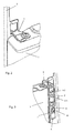
- the assembly sequence of the side wall 2 is shown on a preassembled front wall 3.
- the front wall 3 is fixed to the bottom module, not shown, which is thus placed in a vertical position, in which case, according to the direction of the arrow I, the side wall 2 initially brought to the fasteners on the front wall 3 is, in which case the side wall 2 in connection with the front wall 3, this is spent in accordance with the direction of the arrow II in the holding position, as shown in the third illustration.
- the side walls 2 for frameless construction of the housing 1 for alignment in height (Z-orientation) and / or in the lateral inclination (Y-orientation) with respect to the front wall 3 on pre-assembled elements 4 on the front wall 3 and by incorporating a trained as an angle holding element 5 on the side wall 2 can be fixed.
- the assembled elements 4 are formed of hooks 6, which are fixed to the Abkantungsprofil 7 of the front wall 3.
- the single hook 6 on the front wall 3 cooperates with a keyhole punching 8 arranged on the fold profile of the side wall 2 in the assembled state, as shown in particular in FIGS FIGS. 7, 8 . 9 and 10 will be shown. Also, this is in the FIG.
- the holding member 5 rests with its horizontally extending leg on the upper edge region of the front wall 3, and the hook 6 is inserted in the keyhole punching 8.
- the vertically extending leg of the holding element 5 designed as an angle is fastened here by means of a screw connection 5.1 and a conical stamping 5.2 on the side wall 2, wherein the conical stamping 5.2 effects an anti-rotation.
- the single hook 6 consists of a plastic molded part, which has a substantially rectangular shape for fixing the side wall 2.
- the rectangular shape is particularly in the FIGS. 7 and 8 clearly recognize where in a sectional plane, the interaction of the hook 6 with the keyhole punching 8 in the side wall 2 can be seen.
- the hook 6 defines with its lateral contact surfaces 9 and 10 of the rectangular shape, the inclination of the side wall 2 to the front wall 3 in the keyhole punching 8.
- the adjusted position of the side wall 2 is made, in particular, the contact surfaces 8, 9 make the alignment of the side wall 2 in the Y-orientation.
- the height of the side wall 2 relative to the fixed front wall 3 takes place here exclusively on the holding element 5, which is designed as an angle element such that it rests on the upper edge of the front wall 3, as in particular in the FIG. 3 will be shown.
- the hook 6 has a chamfer 11, which is given for defined installation position in a hole punching 12 on the fold profile 13 of the front wall 3.
- the chamfer 11 is here in particular in the FIG. 6 clearly seen where in the plan view of the hook 6 is shown in rear view, where clearly the chamfer 11 can be seen on the rectangular profile, which in turn is in operative connection with a chamfered punched in the front wall 3 compliant.
- the hook 6 is designed to fix in the hole punching 12 at the Abkantungsprofil 7 of the front wall 3 expansion dowel-like.
- the hook 6 consists here for fixing in the hole punching 12 of two locking lugs 14 and 15, which engage behind the opening edge of the hole punching 12 in the inserted state. Between the locking lugs 14 and 15, a screw 16 can be screwed, which in particular spreads the two locking lugs 14 and 15 such that a fixed position of the hook 6 is given in the hole punching 12.
- the holding element 5, as shown in the FIGS. 8 . 9 and 10 is shown mounted and the hook 6 is pre-assembled on the front wall 3, then by joining the holding element 5 is located on the front wall 3, wherein the hooks 6 then dive into the side wall 2, as shown in the FIG. 1 is shown in the assembly sequence.
Landscapes
- Engineering & Computer Science (AREA)
- Textile Engineering (AREA)
- Casings For Electric Apparatus (AREA)
Abstract
Description
- Gehäuse für Haushaltsgeräte wie beispielsweise Wäschetrockner, Waschmaschine, Geschirrspülmaschine oder dergleichen.
- Die Erfindung betrifft ein Gehäuse für Haushaltsgeräte wie beispielsweise Wäschetrockner, Waschmaschine, Geschirrspülmaschine oder dergleichen, welches in seiner Grundbauform ein Bodenmodul, eine Rückwand, Seitenwände und eine Vorderwand umfasst.
- Aus dem Stand der Technik sind gemäß der
DE 103 03 131 , derDE 198 23 424 sowie aus derDE 38 13 462 Waschmaschinengehäuse bzw. Gehäuse für Haushaltsgeräte bekannt. Bei diesen aus dem Stand der Technik bekannten Gehäusen gibt es unterschiedliche Bauformen für die jeweilige Oberfläche oder Montageart, was eine frühe Variantenbildung beim Gehäuseaufbau erfordert. - Bei den aus dem Stand der Technik bekannten Gehäusen, welche einen eigenständigen inneren Rahmen aufweisen, ist es erforderlich, dass die von außen auf das Gerät wirkenden Lasten passend verteilt werden. Die von außen sichtbaren Spaltbilder sollen dabei möglichst eng und gleichmäßig sein. Zudem sollen die gewählten Lösungen möglichst auch montagefreundlich sein.
- Der Erfindung stellt sich das Problem, ein rahmenloses Gehäuse für Haushaltsgeräte, wie beispielsweise einen Wäschetrockner, Waschmaschine, Geschirrspüler oder dergleichen, derart bereit zu stellen, welches ein Einheitsgehäuse mit Variantenbildung durch Anbauteile und geeigneter Verbindungstechnik umfasst.
- Erfindungsgemäß wird dieses Problem mit den Merkmalen des Patentanspruchs 1 gelöst. Vorteilhafte Ausgestaltungen und Weiterbildungen der Erfindung ergeben sich aus den nachfolgenden Unteransprüchen.
- Die mit der Erfindung erreichten Vorteile bestehen nun darin, dass mit der erfindungsgemäßen Lösung eine genaue Höhenposition der Seitenwände gewährleistet wird. Dabei wird ebenfalls eine genaue Gesamtbreite des Gerätes, Breite Seitenwand zu Seitenwand gewährleistet. Zudem ergibt sich eine einfachere Montage der Seitenwände, wobei von außen sichtlich wirkende Lasten aufgenommen werden können und ins Gerät abgeleitet werden. Die von außen sichtbaren Spaltbilder sind eng und gleichmäßig ausgestaltet. Die exakte Höhenposition der Seitenwände ist hierbei für das Spaltbild gewährleistet und somit für die Spritzwassersicherheit und die Elektrosicherheit des Gerätes. Die Seitenwände werden vorne an Anbindungselementen, wie beispielsweise Haken, an der Vorderwand eingehängt. Somit gibt die Breite der Vorderwand quasi die Distanz der Seitenwände zueinander vor, und damit die Gesamtgerätebreite. Dabei können die Seitenwände einfach montiert aber auch im Bedarfsfall demontiert werden.
- Bei der erfindungsgemäßen Lösung werden Haken eingesetzt, die nur für die Ausrichtung in der Y-Ebene der Seitenwände zuständig sind, also nicht für die Höhenposition der Seitenwand zur Vorderwand, das heißt, die Seitenwand liegt nicht im montierten Zustand auf den Haken auf. Die Haken werden in der Vormontage der Baugruppe montiert und mittels Schrauben an der Vorderwand fixiert. Eine Einstellung bzw. Leere für die Haken wird dabei nicht benötigt. Die auf der Vorderwand aufliegenden Winkel werden über Kegelprägungen, welche eine Verdrehsicherung bewirken, an der Seitenwand montiert und positioniert. Eine Verschraubung des Winkels dient zur Fixierung des Formschlusses und zur Kraftübertragung. Um Fehlmontagen der Haken an der Vorderwand zu vermeiden, ist der rechteckige Grundkörper des Hakens, der in die Vorderwand eintaucht, an einer Ecke deutlich erkennbar angefast, was sich auch im Lochbild an der Vorderwand wieder spiegelt. Rastnasen am Haken ermöglichen eine Vorrastung des Hakens an der Vorderwand, so dass der Haken nach dem Einstecken in die Vorderwand selbsthaftend an der Vorderwand losgelassen werden kann, um dann die Schraube zur Sicherung bzw. Klemmung des Hakens setzen zu können. Ist der Haken an der Vorderwand montiert und in seiner montierten Position festgelegt, kann nun die Seitenwand in einfacher Weise an die Vorderwand angehängt werden. Eine Abstützung der Seitenwand in der Höhe ergibt sich durch das als Winkel ausgebildete Halteelement, welches an der Seitenwand vormontiert ist.
- Gemäß der Erfindung wird hierzu vorgeschlagen, dass die Seitenwände zum rahmenlosen Aufbau des Gehäuses zur Ausrichtung in der Höhe und/oder in der seitlichen Neigung gegenüber der Vorderwand an in der Vormontage montierten Elementen an der Vorderwand sowie unter Einbindung jeweils eines Halteelementes an der Seitenwand festgelegt sind. Hierbei bestehen die montierten Elemente aus Haken, die an dem Abkantungsprofil der Vorderwand festgelegt sind. Die Halteelemente bestehen aus Winkelelementen, welche mittels einer Kegelprägung jeweils an der Seitenwand festegelegt sind.
- Nach einer besonders vorteilhaften Ausgestaltung der Erfindung wirkt der einzelne Haken an der Vorderwand mit einem am Abkantungsprofil der Seitenwand angeordneten Schlüssellochstanzung im zusammengefügten Zustand zusammen. Der einzelne Haken besteht hierbei aus einem Kunststoffformteil, der im Wesentlichen eine Rechteckform zur Festlegung an der Seitenwand aufweist. Der Haken als solches legt hierbei mit seinen seitlichen Anlageflächen der Rechteckform die Neigung der Seitenwand zur Vorderwand in der Schlüssellochstanzung fest.
- Nach einer Weiterbildung der Erfindung weist der einzelne Haken eine Anfasung auf, zur definierten Einbaulage in einer an dem Abkantungsprofil der Vorderwand vorgesehenen Lochstanzung. Zur festen Einbindung des Hakens in der Lochausstanzung an dem Abkantungsprofil der Vorderwand ist der Haken spreizdübelartig ausgebildet. Der Haken umfasst hierbei zur Festlegung in der Lochstanzung zwei Rastnasen, zwischen denen eine Schraube eindrehbar ist. Um insbesondere die Seitenwand leicht an der Vorderwand einfädeln zu können, weist der Haken eine Einfädelprofilierung auf, die im Wesentlichen an dem Hakenelement aus einem horizontal angeformten Steg mit Schrägflanken ausgebildet ist.
- Ein Ausführungsbeispiel der Erfindung ist in den Zeichnungen rein schematisch dargestellt und wird nachfolgend näher beschrieben. Es zeigt:
- Figur 1
- eine Abfolge der Montage in Seitenansicht, wobei in der Abfolge Figur a, b und c das Ansetzen einer Seitenwand an einer fixierten Vorderwand eines Gehäuses dargestellt ist;
- Figur 2
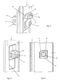
- eine perspektivische Detailansicht der Anbindung der Seitenwand an der Vorderwand mit dem als Winkel ausgebildeten Halteelement;
- Figur 3
- eine weitere perspektivische Darstellung gemäß der
Figur 2 in Rückansicht in Anbindung des Hakens mit dem Halteelement; - Figur 4
- eine perspektivische Darstellung des Hakens an dem Abkantungsprofil der Vorderwand;
- Figur 5
- eine Rückansicht des Hakens an dem Abkantungsprofil der Vorderwand;
- Figur 6
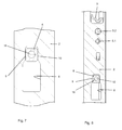
- eine Draufsicht in Rückansicht des Hakens an dem Abkantungsprofil der Vorderwand;
- Figur 7
- eine Draufsicht auf die Seitenwand in Zusammenwirkung des Hakens mit der Schlüssellochstanzung in der Seitenwand;
- Figur 8
- eine weitere Ansicht ebenfalls in Rückansicht des Zusammenwirkens des Hakens mit der Schlüssellochstanzung sowie der Einbindung des Halteelementes an der Seitenwand;
- Figur 9
- eine geschnittene Darstellung der Seitenwand in Einbindung des Hakens und des Halteelementes in einer ersten Ansicht; und
- Figur 10
- eine weitere Seitenansicht in einer anderen Schnittdarstellung des Hakens in Einbindung des Halteelementes.
- Die
Figuren 1 ,2 und 3 zeigen Gehäusebereiche eines Gehäuses 1 für Haushaltsgeräte, wie beispielsweise einen Wäschetrockner, eine Waschmaschine, eine Geschirrspülmaschine oder dergleichen, welches in seiner Grundbauform ein nicht näher dargestelltes Bodenmodul, eine Rückwand sowie Seitenwände 2 und eine Vorderwand 3 umfasst. In derFigur 1 ist insbesondere die Montageabfolge der Seitenwand 2 an eine vormontierte Vorderwand 3 dargestellt. Dabei wird zunächst die Vorderwand 3 an dem nicht näher dargestellten Bodenmodul festgelegt, die somit in eine senkrechte Lage gestellt wird, wobei dann gemäß der Pfeilrichtung I zunächst die Seitenwand 2 an die Befestigungselemente an der Vorderwand 3 herangeführt wird, wobei dann die Seitenwand 2 in Anbindung an der Vorderwand 3 diese gemäß der Pfeilrichtung II in die haltende Lage verbracht wird, wie dies in der dritten Darstellung gezeigt wird. - Um dies zu ermöglichen sind die Seitenwände 2 zum rahmenlosen Aufbau des Gehäuses 1 zur Ausrichtung in der Höhe (Z-Ausrichtung) und/oder in der seitlichen Neigung (Y- Ausrichtung) gegenüber der Vorderwand 3 an in der Vormontage montierten Elementen 4 an der Vorderwand 3 und unter Einbindung eines als Winkel ausgebildeten Halteelementes 5 an der Seitenwand 2 festlegbar. Wie insbesondere in den
Figuren 3 ,4, 5, 6 zu erkennen ist, sind die montierten Elemente 4 aus Haken 6 gebildet, die an dem Abkantungsprofil 7 der Vorderwand 3 festgelegt sind. Der einzelne Haken 6 an der Vorderwand 3 wirkt mit einer am Abkantungsprofil der Seitenwand 2 angeordneten Schlüssellochstanzung 8 im zusammengefügten Zustand zusammen, wie dies insbesondere in denFiguren 7, 8 ,9 und 10 gezeigt wird. Auch ist dies in derFigur 3 in der Rückansicht zu erkennen, wo das Halteelement 5 mit seinem horizontal verlaufenden Schenkel auf dem oberen Randbereich der Vorderwand 3 aufliegt, und der Haken 6 in der Schlüssellochstanzung 8 eingeführt ist. Der vertikal verlaufende Schenkel des als Winkel ausgebildeten Halteelementes 5 ist hierbei mittels einer Verschraubung 5.1 und einer Kegelprägung 5.2 an der Seitenwand 2 befestigt, wobei die Kegelprägung 5.2 eine Verdrehsicherung bewirkt. - Wie insbesondere aus den
Figuren 5, 6 ,9 und 10 zu erkennen ist, besteht der einzelne Haken 6 aus einem Kunststoffformteil, wobei dieses im Wesentlichen eine Rechteckform zur Festlegung der Seitenwand 2 aufweist. Die Rechteckform ist insbesondere in denFiguren 7 und 8 deutlich zu erkennen, wo in einer Schnittebene das Zusammenwirken des Hakens 6 mit der Schlüssellochstanzung 8 in der Seitenwand 2 ersichtlich ist. Nach einer besonders vorteilhaften Ausgestaltung der Erfindung legt hierbei der Haken 6 mit seinen seitlichen Anlageflächen 9 und 10 der Rechteckform die Neigung der Seitenwand 2 zur Vorderwand 3 in der Schlüssellochstanzung 8 fest. Somit wird beim Einhängen der Seitenwand 2 in die Schlüssellochstanzung 8 die justierte Lage der Seitenwand 2 vorgenommen, wobei insbesondere die Anlageflächen 8, 9 die Ausrichtung der Seitenwand 2 in der Y-Ausrichtung vornehmen. Die Höhenlage der Seitenwand 2 gegenüber der fixierten Vorderwand 3 erfolgt hierbei ausschließlich über das Halteelement 5, welches als Winkelelement derart ausgestaltet ist, dass es auf dem oberen Rand der Vorderwand 3 aufliegt, wie dies insbesondere in derFigur 3 gezeigt wird. - Um dem Haken 6 hierbei eine definierte Einbaulage zu vermitteln, weist der Haken 6 eine Anfasung 11 auf, welche zur definierten Einbaulage in einer Lochstanzung 12 an dem Abkantungsprofil 13 der Vorderwand 3 gegeben ist. Die Anfasung 11 ist hierbei insbesondere in der
Figur 6 deutlich zu erkennen, wo in der Draufsicht der Haken 6 in Rückansicht gezeigt ist, wo deutlich die Anfasung 11 an dem Rechteckprofil zu erkennen ist, die wiederum in Wirkverbindung mit einer angefasten Ausstanzung in der Vorderwand 3 konform geht. Wie insbesondere aus denFiguren 4 und 5 , aber auch aus derFigur 10 deutlich zu erkennen ist, ist der Haken 6 zur Festlegung in der Lochstanzung 12 an dem Abkantungsprofil 7 der Vorderwand 3 spreizdübelartig ausgebildet. Der Haken 6 besteht hierbei zur Festlegung in der Lochstanzung 12 aus zwei Rastnasen 14 und 15, die im gesteckten Zustand den Öffnungsrand der Lochstanzung 12 hintergreifen. Zwischen die Rastnasen 14 und 15 ist eine Schraube 16 eindrehbar, die insbesondere die beiden Rastnasen 14 und 15 derart aufspreizt, dass eine feste Lage des Hakens 6 in der Lochstanzung 12 gegeben ist. - Wie insbesondere aus der
Figur 4 in Zusammenschau mit denFiguren 9 und 10 zu erkennen ist, weist der Haken 6 zur Einfädelung an der Schlüssellochstanzung 8 am Seitenwandprofil eine Einfädelprofilierung 17 auf, wobei die Einfädelprofilierung 17 an dem Haken 6 aus einem horizontal geformten Steg 18 mit Schrägflanken 19 und 20 gebildet ist. Es versteht sich nun von selbst, dass, wenn das Halteelement 5, wie dies in denFiguren 8 ,9 und 10 dargestellt ist, montiert ist und der Haken 6 an der Vorderwand 3 entsprechend vormontiert ist, dann durch Zusammenfügen das Halteelement 5 auf der Vorderwand 3 liegt, wobei die Haken 6 dann in die Seitenwand 2 eintauchen, wie dies in derFigur 1 in der Montagefolge gezeigt wird.
Claims (11)
- Gehäuse (1) für Haushaltsgeräte wie beispielsweise Wäschetrockner, Waschmaschine, Geschirrspülmaschine oder dergleichen, welches in seiner Grundbauform ein Bodenmodul eine Rückwand, Seitenwände (2) und eine Vorderwand (3) umfasst,
dadurch gekennzeichnet,
dass die Seitenwände (2) zum rahmenlosen Aufbau des Gehäuses (1) zur Ausrichtung in der Höhe und/oder in der seitlichen Neigung gegenüber der Vorderwand (3) an in der Vormontage montierten Elementen (4) an der Vorderwand (3) sowie unter Einbindung eines Halteelementes (5) an der Seitenwand (2) festlegbar sind. - Gehäuse nach Anspruch 1,
dadurch gekennzeichnet,
dass die justierten Elemente (4) aus Haken (6) bestehen, die an dem Abkantungsprofil (7) der Vorderwand (3) festgelegt sind, wobei die Halteelemente (5) aus Winkelelementen bestehen, welche mittels einer Kegelprägung jeweils an der Seitenwand (2) festgelegt sind. - Gehäuse nach Anspruch 2,
dadurch gekennzeichnet,
dass der einzelne Haken (6) an der Vorderwand (3) mit einer am Abkantungsprofil der Seitenwand (2) angeordneten Schlüssellochstanzung (8) im zusammengefügten Zustand zusammenwirkt. - Gehäuse nach Anspruch 3,
dadurch gekennzeichnet,
dass der einzelne Haken (6) aus einem Kunststoffformteil besteht. - Gehäuse nach Anspruch 4,
dadurch gekennzeichnet,
dass der einzelne Haken (6) im wesentlichen eine Rechteckform zur Festlegung der Seitenwand (2) aufweist. - Gehäuse nach Anspruch 5,
dadurch gekennzeichnet,
dass der Haken (6) mit seinen seitlichen Anlageflächen (9) und (10) der Rechteckform die Neigung der Seitenwand (2) zur Vorderwand (3) in der Schlüssellochstanzung (8) festlegt. - Gehäuse nach Anspruch 6,
dadurch gekennzeichnet,
dass der Haken (6) wenigstens eine Anfasung (11) aufweist zur definierte Einbaulage in einer Lochstanzung (12) an dem Abkantungsprofil (13) der Vorderwand (3). - Gehäuse nach Anspruch 7,
dadurch gekennzeichnet,
dass der Haken (6) zur Festlegung in der Lochstanzung (12) an dem Abkantungsprofil (13) der Vorderwand (3) spreizdübelartig ausgebildet ist. - Gehäuse nach Anspruch 8,
dadurch gekennzeichnet,
dass der Haken (6) zur Festlegung in der Lochstanzung (12) aus zwei Rastnasen (14) und (15) besteht, zwischen denen eine Schraube (16) eindrehbar ist. - Gehäuse nach Anspruch 9,
dadurch gekennzeichnet,
dass der Haken (6) zur Einfädelung an der Schlüssellochstanzung (8) am Seitenwandprofil eine Einfädelprofilierung (17) aufweist. - Gehäuse nach Anspruch 10,
dadurch gekennzeichnet,
dass die Einfädelprofilierung (17) an dem Haken (6) aus einem horizontal angeformten Steg (18) mit Schrägflanken (19) und (20) gebildet ist.
Applications Claiming Priority (1)
| Application Number | Priority Date | Filing Date | Title |
|---|---|---|---|
| DE201310102507 DE102013102507A1 (de) | 2013-03-13 | 2013-03-13 | Gehäuse für Haushaltsgeräte wie beispielsweise Wäschetrockner, Waschmaschine, Geschirrspülmaschine oder dergleichen |
Publications (2)
| Publication Number | Publication Date |
|---|---|
| EP2778274A1 true EP2778274A1 (de) | 2014-09-17 |
| EP2778274B1 EP2778274B1 (de) | 2016-11-09 |
Family
ID=50239460
Family Applications (1)
| Application Number | Title | Priority Date | Filing Date |
|---|---|---|---|
| EP14158552.1A Not-in-force EP2778274B1 (de) | 2013-03-13 | 2014-03-10 | Gehäuse für Haushaltsgeräte wie beispielsweise Wäschetrockner, Waschmaschine, Geschirrspülmaschine oder dergleichen |
Country Status (2)
| Country | Link |
|---|---|
| EP (1) | EP2778274B1 (de) |
| DE (1) | DE102013102507A1 (de) |
Citations (8)
| Publication number | Priority date | Publication date | Assignee | Title |
|---|---|---|---|---|
| DE3813462A1 (de) | 1987-04-21 | 1988-11-10 | Candy Ind Spa | Waschmaschinengehaeuse |
| JPH08299684A (ja) * | 1995-05-10 | 1996-11-19 | Nippon Kentetsu Co Ltd | 洗濯機の前面パネルの取付構造 |
| DE19823424A1 (de) | 1998-05-26 | 1999-12-02 | Aeg Hausgeraete Gmbh | Gerätegehäuse, insbesondere für Haushaltsgroßgeräte |
| KR100261715B1 (ko) * | 1998-01-14 | 2000-07-15 | 구자홍 | 드럼세탁기의 캐비넷커버 결합구조 |
| WO2004011711A1 (en) * | 2002-07-31 | 2004-02-05 | Lg Electronics Inc. | Cabinet for home appliance |
| DE10303131A1 (de) | 2003-01-28 | 2004-07-29 | Electrolux Home Products Corporation N.V. | Haushaltgerät und Gehäuse für das Haushaltgerät |
| KR20060032069A (ko) * | 2004-10-11 | 2006-04-14 | 주식회사 대우일렉트로닉스 | 드럼세탁기의 캐비넷 프론트 커버 결합구조 |
| KR20060114119A (ko) * | 2005-04-27 | 2006-11-06 | 주식회사 대우일렉트로닉스 | 드럼 세탁기용 캐비닛의 프런트 커버 결합구조 |
Family Cites Families (2)
| Publication number | Priority date | Publication date | Assignee | Title |
|---|---|---|---|---|
| KR20050115959A (ko) * | 2004-06-04 | 2005-12-08 | 주식회사 대우일렉트로닉스 | 드럼 세탁기용 캐비닛의 프런트 커버 결합구조 |
| WO2012062673A1 (en) * | 2010-11-12 | 2012-05-18 | Arcelik Anonim Sirketi | A washer/dryer comprising a connection member |
-
2013
- 2013-03-13 DE DE201310102507 patent/DE102013102507A1/de not_active Withdrawn
-
2014
- 2014-03-10 EP EP14158552.1A patent/EP2778274B1/de not_active Not-in-force
Patent Citations (8)
| Publication number | Priority date | Publication date | Assignee | Title |
|---|---|---|---|---|
| DE3813462A1 (de) | 1987-04-21 | 1988-11-10 | Candy Ind Spa | Waschmaschinengehaeuse |
| JPH08299684A (ja) * | 1995-05-10 | 1996-11-19 | Nippon Kentetsu Co Ltd | 洗濯機の前面パネルの取付構造 |
| KR100261715B1 (ko) * | 1998-01-14 | 2000-07-15 | 구자홍 | 드럼세탁기의 캐비넷커버 결합구조 |
| DE19823424A1 (de) | 1998-05-26 | 1999-12-02 | Aeg Hausgeraete Gmbh | Gerätegehäuse, insbesondere für Haushaltsgroßgeräte |
| WO2004011711A1 (en) * | 2002-07-31 | 2004-02-05 | Lg Electronics Inc. | Cabinet for home appliance |
| DE10303131A1 (de) | 2003-01-28 | 2004-07-29 | Electrolux Home Products Corporation N.V. | Haushaltgerät und Gehäuse für das Haushaltgerät |
| KR20060032069A (ko) * | 2004-10-11 | 2006-04-14 | 주식회사 대우일렉트로닉스 | 드럼세탁기의 캐비넷 프론트 커버 결합구조 |
| KR20060114119A (ko) * | 2005-04-27 | 2006-11-06 | 주식회사 대우일렉트로닉스 | 드럼 세탁기용 캐비닛의 프런트 커버 결합구조 |
Also Published As
| Publication number | Publication date |
|---|---|
| DE102013102507A1 (de) | 2014-09-18 |
| EP2778274B1 (de) | 2016-11-09 |
Similar Documents
| Publication | Publication Date | Title |
|---|---|---|
| DE102008055017B4 (de) | Geschirrspülmaschine | |
| EP2703731A2 (de) | Lagerbuchse für ein Haushaltsgerät mit einem pilzförmigen Basiskörper mit einem frontseitig zugänglichen Hohlraum sowie Haushaltsgerät | |
| EP2469182A2 (de) | Auszugsschienensystem für ein Haushaltsgerät | |
| EP2778276B1 (de) | Gehäuse für Haushaltsgeräte sowie Verfahren zur Herrichtung eines Gehäuses für Haushaltsgeräte | |
| EP3026350B1 (de) | Dunstabzugshaube mit einer baueinheit | |
| EP2778274B1 (de) | Gehäuse für Haushaltsgeräte wie beispielsweise Wäschetrockner, Waschmaschine, Geschirrspülmaschine oder dergleichen | |
| EP2778279B1 (de) | Gehäuse für Haushaltsgeräte wie beispielsweise Wäschetrockner, Waschmaschine, Geschirrspülmaschine oder dergleichen | |
| EP2801652B1 (de) | Gehäuse für ein Haushaltsgerät wie beispielsweise einen Wäschetrockner sowie ein Verfahren zur Herstellung eines Gehäuses | |
| AT520816B1 (de) | Montagewinkel und Montageanordnung | |
| EP2778278B1 (de) | Gehäuse für haushaltsgeräte wie beispielsweise einen wäschetrockner, eine waschmaschine, oder dergleichen | |
| DE202015003360U1 (de) | Abdeckelement für eine Gerätewand eines Hausgeräts und Hausgerät mit einem Abdeckelement | |
| EP2778275B1 (de) | Gehäuse für Haushaltsgeräte wie beispielsweise Wäschetrockner, Waschmaschine, Geschirrspülmaschine oder dergleichen | |
| DE10212145B4 (de) | Befestigungsanordnung zur festen Anbringung eines Fahrzeugheizgerätes an einem Fahrzeug | |
| EP2778280B1 (de) | Gehäuse für haushaltsgeräte wie beispielsweise einen wäschetrockner, eine waschmaschine oder dergleichen | |
| EP2777469B1 (de) | Gehäuse für Haushaltsgeräte wie beispielsweise Wäschetrockner, Waschmaschine, Geschirrspülmaschine oder dergleichen | |
| AT520822A4 (de) | Schubladenseitenwand | |
| EP2778273B1 (de) | Gehäuse für haushaltsgeräte wie beispielsweise wäschetrockner, waschmaschine, geschirrspülmaschine oder dergleichen | |
| DE102017107438B4 (de) | Gehäuse für Haushaltsgeräte wie beispielsweise Wäschetrockner, Waschmaschine, Geschirrspüler oder dergleichen | |
| DE102013103029B3 (de) | Frontbeschickbare Wäschebehandlungsmaschine | |
| EP3067495B1 (de) | Haltelement eines beschlagteils eines treibstangenbeschlages | |
| DE102014106604A1 (de) | Haushaltsgerät wie besipielsweise ein Wäschetrockner mit einer Wärmepumpeneinheit | |
| DE102014101284B3 (de) | Zargenanordnung sowie Befestigungsplatte | |
| EP1649781B1 (de) | Rahmengestell eines Schubkastens | |
| EP2777470B1 (de) | Gehäuse für Haushaltsgeräte wie beispielsweise Wäschetrockner, Waschmaschine, Geschirrspülmaschine oder dergleichen | |
| DE102014107562A1 (de) | Gehäuse für Haushaltsgeräte und Verbindungselement |
Legal Events
| Date | Code | Title | Description |
|---|---|---|---|
| 17P | Request for examination filed |
Effective date: 20140310 |
|
| AK | Designated contracting states |
Kind code of ref document: A1 Designated state(s): AL AT BE BG CH CY CZ DE DK EE ES FI FR GB GR HR HU IE IS IT LI LT LU LV MC MK MT NL NO PL PT RO RS SE SI SK SM TR |
|
| AX | Request for extension of the european patent |
Extension state: BA ME |
|
| PUAI | Public reference made under article 153(3) epc to a published international application that has entered the european phase |
Free format text: ORIGINAL CODE: 0009012 |
|
| R17P | Request for examination filed (corrected) |
Effective date: 20150317 |
|
| RBV | Designated contracting states (corrected) |
Designated state(s): AL AT BE BG CH CY CZ DE DK EE ES FI FR GB GR HR HU IE IS IT LI LT LU LV MC MK MT NL NO PL PT RO RS SE SI SK SM TR |
|
| 17Q | First examination report despatched |
Effective date: 20150916 |
|
| GRAP | Despatch of communication of intention to grant a patent |
Free format text: ORIGINAL CODE: EPIDOSNIGR1 |
|
| RIC1 | Information provided on ipc code assigned before grant |
Ipc: D06F 39/12 20060101AFI20160616BHEP Ipc: A47L 15/42 20060101ALI20160616BHEP Ipc: D06F 58/20 20060101ALI20160616BHEP |
|
| INTG | Intention to grant announced |
Effective date: 20160712 |
|
| GRAS | Grant fee paid |
Free format text: ORIGINAL CODE: EPIDOSNIGR3 |
|
| GRAA | (expected) grant |
Free format text: ORIGINAL CODE: 0009210 |
|
| AK | Designated contracting states |
Kind code of ref document: B1 Designated state(s): AL AT BE BG CH CY CZ DE DK EE ES FI FR GB GR HR HU IE IS IT LI LT LU LV MC MK MT NL NO PL PT RO RS SE SI SK SM TR |
|
| REG | Reference to a national code |
Ref country code: GB Ref legal event code: FG4D Free format text: NOT ENGLISH |
|
| REG | Reference to a national code |
Ref country code: AT Ref legal event code: REF Ref document number: 844031 Country of ref document: AT Kind code of ref document: T Effective date: 20161115 Ref country code: CH Ref legal event code: EP Ref country code: DE Ref legal event code: R084 Ref document number: 502014001887 Country of ref document: DE |
|
| REG | Reference to a national code |
Ref country code: GB Ref legal event code: 746 Effective date: 20161104 Ref country code: IE Ref legal event code: FG4D Free format text: LANGUAGE OF EP DOCUMENT: GERMAN |
|
| REG | Reference to a national code |
Ref country code: DE Ref legal event code: R096 Ref document number: 502014001887 Country of ref document: DE |
|
| PG25 | Lapsed in a contracting state [announced via postgrant information from national office to epo] |
Ref country code: LV Free format text: LAPSE BECAUSE OF FAILURE TO SUBMIT A TRANSLATION OF THE DESCRIPTION OR TO PAY THE FEE WITHIN THE PRESCRIBED TIME-LIMIT Effective date: 20161109 |
|
| REG | Reference to a national code |
Ref country code: LT Ref legal event code: MG4D |
|
| REG | Reference to a national code |
Ref country code: NL Ref legal event code: MP Effective date: 20161109 |
|
| REG | Reference to a national code |
Ref country code: FR Ref legal event code: PLFP Year of fee payment: 4 |
|
| PG25 | Lapsed in a contracting state [announced via postgrant information from national office to epo] |
Ref country code: SE Free format text: LAPSE BECAUSE OF FAILURE TO SUBMIT A TRANSLATION OF THE DESCRIPTION OR TO PAY THE FEE WITHIN THE PRESCRIBED TIME-LIMIT Effective date: 20161109 Ref country code: GR Free format text: LAPSE BECAUSE OF FAILURE TO SUBMIT A TRANSLATION OF THE DESCRIPTION OR TO PAY THE FEE WITHIN THE PRESCRIBED TIME-LIMIT Effective date: 20170210 Ref country code: LT Free format text: LAPSE BECAUSE OF FAILURE TO SUBMIT A TRANSLATION OF THE DESCRIPTION OR TO PAY THE FEE WITHIN THE PRESCRIBED TIME-LIMIT Effective date: 20161109 Ref country code: NL Free format text: LAPSE BECAUSE OF FAILURE TO SUBMIT A TRANSLATION OF THE DESCRIPTION OR TO PAY THE FEE WITHIN THE PRESCRIBED TIME-LIMIT Effective date: 20161109 Ref country code: NO Free format text: LAPSE BECAUSE OF FAILURE TO SUBMIT A TRANSLATION OF THE DESCRIPTION OR TO PAY THE FEE WITHIN THE PRESCRIBED TIME-LIMIT Effective date: 20170209 |
|
| PG25 | Lapsed in a contracting state [announced via postgrant information from national office to epo] |
Ref country code: HR Free format text: LAPSE BECAUSE OF FAILURE TO SUBMIT A TRANSLATION OF THE DESCRIPTION OR TO PAY THE FEE WITHIN THE PRESCRIBED TIME-LIMIT Effective date: 20161109 Ref country code: ES Free format text: LAPSE BECAUSE OF FAILURE TO SUBMIT A TRANSLATION OF THE DESCRIPTION OR TO PAY THE FEE WITHIN THE PRESCRIBED TIME-LIMIT Effective date: 20161109 Ref country code: PL Free format text: LAPSE BECAUSE OF FAILURE TO SUBMIT A TRANSLATION OF THE DESCRIPTION OR TO PAY THE FEE WITHIN THE PRESCRIBED TIME-LIMIT Effective date: 20161109 Ref country code: IS Free format text: LAPSE BECAUSE OF FAILURE TO SUBMIT A TRANSLATION OF THE DESCRIPTION OR TO PAY THE FEE WITHIN THE PRESCRIBED TIME-LIMIT Effective date: 20170309 Ref country code: PT Free format text: LAPSE BECAUSE OF FAILURE TO SUBMIT A TRANSLATION OF THE DESCRIPTION OR TO PAY THE FEE WITHIN THE PRESCRIBED TIME-LIMIT Effective date: 20170309 Ref country code: RS Free format text: LAPSE BECAUSE OF FAILURE TO SUBMIT A TRANSLATION OF THE DESCRIPTION OR TO PAY THE FEE WITHIN THE PRESCRIBED TIME-LIMIT Effective date: 20161109 Ref country code: FI Free format text: LAPSE BECAUSE OF FAILURE TO SUBMIT A TRANSLATION OF THE DESCRIPTION OR TO PAY THE FEE WITHIN THE PRESCRIBED TIME-LIMIT Effective date: 20161109 |
|
| PG25 | Lapsed in a contracting state [announced via postgrant information from national office to epo] |
Ref country code: CZ Free format text: LAPSE BECAUSE OF FAILURE TO SUBMIT A TRANSLATION OF THE DESCRIPTION OR TO PAY THE FEE WITHIN THE PRESCRIBED TIME-LIMIT Effective date: 20161109 Ref country code: EE Free format text: LAPSE BECAUSE OF FAILURE TO SUBMIT A TRANSLATION OF THE DESCRIPTION OR TO PAY THE FEE WITHIN THE PRESCRIBED TIME-LIMIT Effective date: 20161109 Ref country code: SK Free format text: LAPSE BECAUSE OF FAILURE TO SUBMIT A TRANSLATION OF THE DESCRIPTION OR TO PAY THE FEE WITHIN THE PRESCRIBED TIME-LIMIT Effective date: 20161109 Ref country code: DK Free format text: LAPSE BECAUSE OF FAILURE TO SUBMIT A TRANSLATION OF THE DESCRIPTION OR TO PAY THE FEE WITHIN THE PRESCRIBED TIME-LIMIT Effective date: 20161109 Ref country code: RO Free format text: LAPSE BECAUSE OF FAILURE TO SUBMIT A TRANSLATION OF THE DESCRIPTION OR TO PAY THE FEE WITHIN THE PRESCRIBED TIME-LIMIT Effective date: 20161109 |
|
| REG | Reference to a national code |
Ref country code: DE Ref legal event code: R097 Ref document number: 502014001887 Country of ref document: DE |
|
| PG25 | Lapsed in a contracting state [announced via postgrant information from national office to epo] |
Ref country code: BG Free format text: LAPSE BECAUSE OF FAILURE TO SUBMIT A TRANSLATION OF THE DESCRIPTION OR TO PAY THE FEE WITHIN THE PRESCRIBED TIME-LIMIT Effective date: 20170209 Ref country code: IT Free format text: LAPSE BECAUSE OF FAILURE TO SUBMIT A TRANSLATION OF THE DESCRIPTION OR TO PAY THE FEE WITHIN THE PRESCRIBED TIME-LIMIT Effective date: 20161109 Ref country code: SM Free format text: LAPSE BECAUSE OF FAILURE TO SUBMIT A TRANSLATION OF THE DESCRIPTION OR TO PAY THE FEE WITHIN THE PRESCRIBED TIME-LIMIT Effective date: 20161109 |
|
| PLBE | No opposition filed within time limit |
Free format text: ORIGINAL CODE: 0009261 |
|
| STAA | Information on the status of an ep patent application or granted ep patent |
Free format text: STATUS: NO OPPOSITION FILED WITHIN TIME LIMIT |
|
| 26N | No opposition filed |
Effective date: 20170810 |
|
| REG | Reference to a national code |
Ref country code: CH Ref legal event code: PL |
|
| PG25 | Lapsed in a contracting state [announced via postgrant information from national office to epo] |
Ref country code: MC Free format text: LAPSE BECAUSE OF FAILURE TO SUBMIT A TRANSLATION OF THE DESCRIPTION OR TO PAY THE FEE WITHIN THE PRESCRIBED TIME-LIMIT Effective date: 20161109 Ref country code: SI Free format text: LAPSE BECAUSE OF FAILURE TO SUBMIT A TRANSLATION OF THE DESCRIPTION OR TO PAY THE FEE WITHIN THE PRESCRIBED TIME-LIMIT Effective date: 20161109 |
|
| REG | Reference to a national code |
Ref country code: IE Ref legal event code: MM4A |
|
| PG25 | Lapsed in a contracting state [announced via postgrant information from national office to epo] |
Ref country code: LU Free format text: LAPSE BECAUSE OF NON-PAYMENT OF DUE FEES Effective date: 20170310 |
|
| PG25 | Lapsed in a contracting state [announced via postgrant information from national office to epo] |
Ref country code: IE Free format text: LAPSE BECAUSE OF NON-PAYMENT OF DUE FEES Effective date: 20170310 Ref country code: CH Free format text: LAPSE BECAUSE OF NON-PAYMENT OF DUE FEES Effective date: 20170331 Ref country code: LI Free format text: LAPSE BECAUSE OF NON-PAYMENT OF DUE FEES Effective date: 20170331 |
|
| REG | Reference to a national code |
Ref country code: BE Ref legal event code: MM Effective date: 20170331 |
|
| REG | Reference to a national code |
Ref country code: FR Ref legal event code: PLFP Year of fee payment: 5 |
|
| PG25 | Lapsed in a contracting state [announced via postgrant information from national office to epo] |
Ref country code: BE Free format text: LAPSE BECAUSE OF NON-PAYMENT OF DUE FEES Effective date: 20170331 |
|
| PG25 | Lapsed in a contracting state [announced via postgrant information from national office to epo] |
Ref country code: MT Free format text: LAPSE BECAUSE OF FAILURE TO SUBMIT A TRANSLATION OF THE DESCRIPTION OR TO PAY THE FEE WITHIN THE PRESCRIBED TIME-LIMIT Effective date: 20161109 |
|
| PG25 | Lapsed in a contracting state [announced via postgrant information from national office to epo] |
Ref country code: HU Free format text: LAPSE BECAUSE OF FAILURE TO SUBMIT A TRANSLATION OF THE DESCRIPTION OR TO PAY THE FEE WITHIN THE PRESCRIBED TIME-LIMIT; INVALID AB INITIO Effective date: 20140310 |
|
| PG25 | Lapsed in a contracting state [announced via postgrant information from national office to epo] |
Ref country code: CY Free format text: LAPSE BECAUSE OF NON-PAYMENT OF DUE FEES Effective date: 20161109 |
|
| PG25 | Lapsed in a contracting state [announced via postgrant information from national office to epo] |
Ref country code: MK Free format text: LAPSE BECAUSE OF FAILURE TO SUBMIT A TRANSLATION OF THE DESCRIPTION OR TO PAY THE FEE WITHIN THE PRESCRIBED TIME-LIMIT Effective date: 20161109 |
|
| PG25 | Lapsed in a contracting state [announced via postgrant information from national office to epo] |
Ref country code: TR Free format text: LAPSE BECAUSE OF FAILURE TO SUBMIT A TRANSLATION OF THE DESCRIPTION OR TO PAY THE FEE WITHIN THE PRESCRIBED TIME-LIMIT Effective date: 20161109 |
|
| PG25 | Lapsed in a contracting state [announced via postgrant information from national office to epo] |
Ref country code: AL Free format text: LAPSE BECAUSE OF FAILURE TO SUBMIT A TRANSLATION OF THE DESCRIPTION OR TO PAY THE FEE WITHIN THE PRESCRIBED TIME-LIMIT Effective date: 20161109 |
|
| REG | Reference to a national code |
Ref country code: AT Ref legal event code: MM01 Ref document number: 844031 Country of ref document: AT Kind code of ref document: T Effective date: 20190310 |
|
| PG25 | Lapsed in a contracting state [announced via postgrant information from national office to epo] |
Ref country code: AT Free format text: LAPSE BECAUSE OF NON-PAYMENT OF DUE FEES Effective date: 20190310 |
|
| P01 | Opt-out of the competence of the unified patent court (upc) registered |
Effective date: 20230529 |
|
| PGFP | Annual fee paid to national office [announced via postgrant information from national office to epo] |
Ref country code: DE Payment date: 20240331 Year of fee payment: 11 Ref country code: GB Payment date: 20240319 Year of fee payment: 11 |
|
| PGFP | Annual fee paid to national office [announced via postgrant information from national office to epo] |
Ref country code: FR Payment date: 20240326 Year of fee payment: 11 |
|
| REG | Reference to a national code |
Ref country code: DE Ref legal event code: R119 Ref document number: 502014001887 Country of ref document: DE |
|
| GBPC | Gb: european patent ceased through non-payment of renewal fee |
Effective date: 20250310 |
|
| PG25 | Lapsed in a contracting state [announced via postgrant information from national office to epo] |
Ref country code: DE Free format text: LAPSE BECAUSE OF NON-PAYMENT OF DUE FEES Effective date: 20251001 |
|
| PG25 | Lapsed in a contracting state [announced via postgrant information from national office to epo] |
Ref country code: GB Free format text: LAPSE BECAUSE OF NON-PAYMENT OF DUE FEES Effective date: 20250310 |
|
| PG25 | Lapsed in a contracting state [announced via postgrant information from national office to epo] |
Ref country code: FR Free format text: LAPSE BECAUSE OF NON-PAYMENT OF DUE FEES Effective date: 20250331 |