EP2777947A1 - Rollvorrichtung zum Ansetzen an ein Standgestell eines Wäschetrockners und Wäschetrockner - Google Patents
Rollvorrichtung zum Ansetzen an ein Standgestell eines Wäschetrockners und Wäschetrockner Download PDFInfo
- Publication number
- EP2777947A1 EP2777947A1 EP14158119.9A EP14158119A EP2777947A1 EP 2777947 A1 EP2777947 A1 EP 2777947A1 EP 14158119 A EP14158119 A EP 14158119A EP 2777947 A1 EP2777947 A1 EP 2777947A1
- Authority
- EP
- European Patent Office
- Prior art keywords
- carrier body
- stand frame
- rolling device
- roller
- rolling
- Prior art date
- Legal status (The legal status is an assumption and is not a legal conclusion. Google has not performed a legal analysis and makes no representation as to the accuracy of the status listed.)
- Granted
Links
Images

Classifications
-
- B—PERFORMING OPERATIONS; TRANSPORTING
- B60—VEHICLES IN GENERAL
- B60B—VEHICLE WHEELS; CASTORS; AXLES FOR WHEELS OR CASTORS; INCREASING WHEEL ADHESION
- B60B33/00—Castors in general ; Anti-clogging castors
- B60B33/0002—Castors in general ; Anti-clogging castors assembling to the object, e.g. furniture
- B60B33/0005—Castors in general ; Anti-clogging castors assembling to the object, e.g. furniture characterised by mounting method
-
- B—PERFORMING OPERATIONS; TRANSPORTING
- B60—VEHICLES IN GENERAL
- B60B—VEHICLE WHEELS; CASTORS; AXLES FOR WHEELS OR CASTORS; INCREASING WHEEL ADHESION
- B60B33/00—Castors in general ; Anti-clogging castors
- B60B33/0002—Castors in general ; Anti-clogging castors assembling to the object, e.g. furniture
- B60B33/0005—Castors in general ; Anti-clogging castors assembling to the object, e.g. furniture characterised by mounting method
- B60B33/001—Castors in general ; Anti-clogging castors assembling to the object, e.g. furniture characterised by mounting method by snapping, clicking or latching in
-
- B—PERFORMING OPERATIONS; TRANSPORTING
- B60—VEHICLES IN GENERAL
- B60B—VEHICLE WHEELS; CASTORS; AXLES FOR WHEELS OR CASTORS; INCREASING WHEEL ADHESION
- B60B33/00—Castors in general ; Anti-clogging castors
- B60B33/0002—Castors in general ; Anti-clogging castors assembling to the object, e.g. furniture
- B60B33/0015—Castors in general ; Anti-clogging castors assembling to the object, e.g. furniture characterised by adaptations made to castor
- B60B33/0023—Castors in general ; Anti-clogging castors assembling to the object, e.g. furniture characterised by adaptations made to castor in the form of specific adaptations to the form of the object
-
- B—PERFORMING OPERATIONS; TRANSPORTING
- B60—VEHICLES IN GENERAL
- B60B—VEHICLE WHEELS; CASTORS; AXLES FOR WHEELS OR CASTORS; INCREASING WHEEL ADHESION
- B60B33/00—Castors in general ; Anti-clogging castors
- B60B33/006—Castors in general ; Anti-clogging castors characterised by details of the swivel mechanism
- B60B33/0065—Castors in general ; Anti-clogging castors characterised by details of the swivel mechanism characterised by details of the swivel axis
- B60B33/0071—Castors in general ; Anti-clogging castors characterised by details of the swivel mechanism characterised by details of the swivel axis the swivel axis being inclined
-
- B—PERFORMING OPERATIONS; TRANSPORTING
- B60—VEHICLES IN GENERAL
- B60B—VEHICLE WHEELS; CASTORS; AXLES FOR WHEELS OR CASTORS; INCREASING WHEEL ADHESION
- B60B33/00—Castors in general ; Anti-clogging castors
- B60B33/0036—Castors in general ; Anti-clogging castors characterised by type of wheels
- B60B33/0039—Single wheels
-
- B—PERFORMING OPERATIONS; TRANSPORTING
- B60—VEHICLES IN GENERAL
- B60B—VEHICLE WHEELS; CASTORS; AXLES FOR WHEELS OR CASTORS; INCREASING WHEEL ADHESION
- B60B33/00—Castors in general ; Anti-clogging castors
- B60B33/0047—Castors in general ; Anti-clogging castors characterised by details of the rolling axle
- B60B33/0049—Castors in general ; Anti-clogging castors characterised by details of the rolling axle the rolling axle being horizontal
-
- B—PERFORMING OPERATIONS; TRANSPORTING
- B60—VEHICLES IN GENERAL
- B60B—VEHICLE WHEELS; CASTORS; AXLES FOR WHEELS OR CASTORS; INCREASING WHEEL ADHESION
- B60B33/00—Castors in general ; Anti-clogging castors
- B60B33/0047—Castors in general ; Anti-clogging castors characterised by details of the rolling axle
- B60B33/0055—Castors in general ; Anti-clogging castors characterised by details of the rolling axle the rolling axle intersects swivel axis
-
- B—PERFORMING OPERATIONS; TRANSPORTING
- B60—VEHICLES IN GENERAL
- B60B—VEHICLE WHEELS; CASTORS; AXLES FOR WHEELS OR CASTORS; INCREASING WHEEL ADHESION
- B60B33/00—Castors in general ; Anti-clogging castors
- B60B33/006—Castors in general ; Anti-clogging castors characterised by details of the swivel mechanism
- B60B33/0065—Castors in general ; Anti-clogging castors characterised by details of the swivel mechanism characterised by details of the swivel axis
- B60B33/0068—Castors in general ; Anti-clogging castors characterised by details of the swivel mechanism characterised by details of the swivel axis the swivel axis being vertical
-
- B—PERFORMING OPERATIONS; TRANSPORTING
- B60—VEHICLES IN GENERAL
- B60B—VEHICLE WHEELS; CASTORS; AXLES FOR WHEELS OR CASTORS; INCREASING WHEEL ADHESION
- B60B33/00—Castors in general ; Anti-clogging castors
- B60B33/006—Castors in general ; Anti-clogging castors characterised by details of the swivel mechanism
- B60B33/0065—Castors in general ; Anti-clogging castors characterised by details of the swivel mechanism characterised by details of the swivel axis
- B60B33/0073—Castors in general ; Anti-clogging castors characterised by details of the swivel mechanism characterised by details of the swivel axis the swivel axis being symmetrical to wheel or wheels
-
- D—TEXTILES; PAPER
- D06—TREATMENT OF TEXTILES OR THE LIKE; LAUNDERING; FLEXIBLE MATERIALS NOT OTHERWISE PROVIDED FOR
- D06F—LAUNDERING, DRYING, IRONING, PRESSING OR FOLDING TEXTILE ARTICLES
- D06F57/00—Supporting means, other than simple clothes-lines, for linen or garments to be dried or aired
- D06F57/08—Folding stands
Definitions
- the invention relates to a rolling device for attachment to a rack of a tumble dryer with at least one, attachable to a mounting portion of the rack frame roller. Furthermore, the invention relates to a tumble dryer with such a rolling device.
- Dryers of the type concerned here have an upper drying level, which may be formed, for example, by a plurality of washing lines extending parallel to one another.
- This drying level is usually defined by a frame, which can be parked on a stand on the ground or other ground.
- the user will want it that the rack is safe and secure to hang on the one hand undisturbed by an unwanted movement of the tumble dryer laundry and on the other to avoid that, for example, when drying outdoors by wind or is moved unintentionally by an inclined mounting plane of the tumble dryer.
- the rack can take different forms.
- One possible form is the so-called scissors-type frame, in which two feet connected to the upper drying level extend in a cross-shaped X-shape to the bottom, where they are usually placed over two horizontal cross members.
- Another embodiment of the rack frame has two U-shaped bracket, which are usually provided hinged at the ends of the drying level and extend with the closed area down in the direction of the mounting plane. These brackets have horizontal, ground-level transverse profiles, which may have additional, usually made of plastic glides or installation elements.
- a further preferred embodiment of the tumble dryer uses multi-part brackets, which are connected to each other at the lower corners via corner connecting elements, which are usually made of plastic.
- Exemplary of the above-described stands are, for example, from the EP 2 527 516 A1 known stand frame.
- the mentioned basic forms of the rack are shown in the individual figures, however, the application of the present invention is not limited to this form of tumble dryer, so-called tower dryer with multiple, superimposed or even juxtaposed planes can in conjunction with the present invention be used.
- a generic rolling device for tumble dryer is from the DE 20 2010 015 677 U1 known.
- the known rolling device is formed in the manner of a roller which is divided into two and can be mounted around the lower, ground-level and horizontally extending rod of the rack while leaving a game.
- This roller then serves as a rolling aid, so that the tumble dryer can be lifted on one side on the opposite side so that it only has contact with the ground via the roller. Since this roller is rotatably held on the horizontal rod, the clothes dryer can now be moved rolling.
- the disadvantage of the known rolling aid is that on the one hand, the assembly effort is relatively large and on the other hand on the one hand, the roller is always active, so that the stability of the dryer is limited to the opposite side. On the other hand, the dryer must be slightly inclined due to the additional roller.
- Another disadvantage is that the roller is not steerable and because of its relatively high directional stability barely allows cornering, so that it is difficult, for example, to rank the tumble dryer thus made into a corner or a narrow niche.
- the object of the invention is therefore to provide an attachable as possible to existing dryer tumble aid that allows easy handling of the rollable tumble dryer while safe standing and cost-effective production.
- the carrier body may consist of an additional element that is attached to the rack of the tumble dryer and fastened there.
- the roller is rotatably mounted about the roll axis or alternatively it can be used as a rolling means a bordered and mounted on the socket on the support body ball.
- a preferred embodiment uses a carrier body on which the rolling means designed as a roller roll is rotatably mounted in addition to a rotational axis arranged at an angle to the roll axis.
- the carrier body can be subsequently attached to the stand frame.
- this support body can be made of plastic and attached, for example, at the corners of the lower edges of the rack.
- the support body may have a boom, on which a roller is arranged and then includes the bearing of the roller, which is rotatably supported about a horizontal axis on the boom.
- several rollers may be provided on a boom, alternatively, a plurality of cantilevers may be arranged on a support body.
- the carrier body is preferably tool-less connectable to the stand frame. So that the tumble dryer can be sufficiently secure even after fastening of the carrier body, the carrier body is preferably provided in the region of the outer corners. More preferably, the carrier body is formed so that it can be attached to a mounting portion of the rack, said mounting portion is preferably adapted to the shape of the rack in the region of the neck region.
- the support body may have an attachment area which is channel-like with a cross-sectionally U-shaped area, so that the metal bracket can be inserted into this channel.
- the support body engages under the stand frame, so that the weight of the tumble dryer loads on a positioned below the stand frame area of the support body.
- a lateral slippage of the carrier body can be effectively prevented by the fact that the carrier body also receives a vertical portion of the rack, in the above
- the channel is bent analogous to the tube of the stand frame, so that the corner of the bent tube can be inserted into this corresponding curved groove.
- a rolling device is then provided at both corners of this rack.
- the carrier body is preferably connected via an elastic latching force with the stand frame.
- an elastic latching force with the stand frame.
- this can be done by the fact that for insertion of the bars of the rack frame this approach area must first be slightly bent to snap back after insertion again resiliently.
- all other forms of locking connection are possible, if desired, it may also be possible to connect the carrier body via Velcro or screw or other connection means with the stand frame.
- roller is arranged on the carrier body in such a way that two operating states become possible. In a drying position then the roller has no contact with the ground. This means that the tumble dryer is then either on the stand frame or arranged below the stand frame support area of the support body securely and firmly and is thus secured against rolling away. In contrast, the tumble dryer should be movable in a travel position.
- the tumble dryer In order to produce the necessary contact of the running surface of the roller contacting the floor in the travel position, the tumble dryer is lifted slightly on the side opposite the carrier body. So that now the tread can get in contact with the ground by this tilting movement, this is arranged on the cantilevered boom in front of the contact surface with the ground in the drying position. This means that the boom is tilted on tilting of the tumble dryer around the contact line during the drying position down so that the roller lowers on the ground, then after a contact then supported on the ground, so that a further tilting then lifting the complete stand rack causes.
- the roller In order for the above function to be realized, the roller must be arranged offset to the support area of the rack with the ground. Furthermore, it must be offset to the outside, so that the lifting of the opposite end of the stand frame causes the originally arranged above the level of the ground roller is lowered and can be supported on the ground.
- the roller is rotatably mounted on the boom.
- the roller is rotatable by 360 °. This allows a particularly easy maneuvering of the tumble dryer, since it can then be easily moved in all directions.
- a further preferred embodiment of the invention has a height adjustment of the roller.
- This allows the user with a kit to mount the rollers either to realize the above-described double function with a firm standing in the drying position and traversability after unilateral lifting or, if he does not want it and a permanent contact of the roller with the ground prefers
- the roller is rotatably mounted on the arm, wherein the axis of rotation relative to the vertical axis by an angle forwards or backwards is forgiven to realize as desired a lead or caster. Like all other vehicles, this can stabilize the driveability of the mobile tumble dryer and prevent unwanted movements in the lateral direction.
- Another possible embodiment of the invention realizes a switching between the dual function with a firm footing in the non-tilted state and rolling contact after one-sided tilting on the one hand and a permanent rolling function on the other hand, that the support body is either slidably held on the base frame or, if the reel body forward or backward surmounted, tiltable can be attached to the base frame.
- the upwardly extending rod of the rack can pass through the carrier body, which may be held tiltable at a lower position and with two opposite, semi-cylindrical shells which diverge V, extends upward.
- the opening of the two half cylinders is then facing each other and arranged the rod of the rack between these two elements.
- the support body can also be attached to these corner connecting elements.
- the carrier body and also the other parts of the rolling device are preferably made of plastic.
- the support area over which the tumble dryer comes into contact with the floor may be provided with an additional slip-resistant layer.
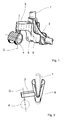
- FIG. 1 shows a first embodiment of a rolling device according to the invention. This rolling device is attached to this dryer in the region of a corner connecting element 2 of a rack 1 of a tumble dryer.
- the clothes dryer has here a stand frame 1 shown here only in the form of two rods, these rods are connected to each other via the corner connecting element 2 such that a lower bar extends horizontally to the ground, in particular to the ground, while a lateral bar upwards Drying level of the clothes dryer runs in which the holding means are arranged for the laundry items.
- Shown here is only one of the two corners of the rack frame 1, on the opposite side, a second corner connecting element 2 is provided. In this way, results in a substantially U-shaped base.
- rollers 4 can be attached to a conventional tumble dryer via the carrier body 6. This can be done either by retrofitting or already ex works, with a factory equipment, the construction of the dryer does not need to be changed.
- the carrier body 6 consists essentially of a middle component, which surrounds the corner connecting element 2 at its corner.
- this middle component has the basic shape of a curved groove.
- the corner connecting element 2 as shown FIG. 1 can be used.
- a boom 3 is provided, at its end in turn the roller 4 is arranged.
- the boom 3 is offset slightly upwards in comparison with the lower region of the carrier body 6 and protrudes forward away from the corner connecting element 2. This means that here extend the base frame 1 and the dryer from the corner connecting element 2 shown in the plane of the paper. The boom 3 is therefore in each case facing away from the opposite foot of the stand frame 1.
- the roller 4 is rotatably mounted on the boom 3 about the rotation axis D. In the illustrated embodiment, the roller 4 can rotate 360 °.
- the support body 6 is formed so that when standing on the stand frame 1 tumble roller 4 is set high compared to a lower support area 5 of the support body 6. This means that when the dryer is stationary, the roller 4 floats freely in the air. Your role as a rolling device receives them only after tilting of the rack 1 to the horizontal tube of the rack 1, the in FIG. 1 is shown in the right pane.
- FIG. 2 schematically another embodiment of the carrier body 6 is shown.
- This carrier body 6 is penetrated by the bottom upwardly extending rod of the standard frame 1 (shown here in phantom) and is mounted in the lower part of this rod such that it sits axially fixed, but is pivotable about this thrust bearing around, with two V shaped upwardly gaping half cylinder limit the pivotal movement of the two half-cylinders of the support body 6.
- the rod of the stand frame 1 can be clamped, so that the support body 6 can be attached to two basic positions on this rod.
- this mounting option at two positions is that the boom 3, which bears here to the left, is also moved by the pivoting of the support body 6 to which it is fastened.
- the axis D and the roller 4, which are located at the end of the boom 3, rotated about a point lying on the rod axis, so that the roller 4 relative to the stand frame 1, depending on whether the left or the right half cylinder in the Rod of the rack 1 is inserted, can be set in a different height relative to the base frame 1.
- the user can therefore manually choose whether he wants a permanent ground contact of the rollers 4 or whether he wants to adjust the rollers 4 so that they only after tilting of the rack 1, as above in connection with FIG. 1 described, come into contact with the ground.
- This embodiment is just one of many conceivable Possibilities, alternatively, a pure height adjustment of the roller 4 on the support body 6 or an axial displacement of the support body 6 may be provided.
- FIG. 3 shows a simpler embodiment of the invention.
- a boom 3 is formed as a solid arm.
- the roller 4 is mounted, but not rotatable here with a rotatable axis of rotation but only in the roll axis of the roller 4. This caster can thus not be used to guide the stand frame, which is quite desired by some users to move the stand provided with this role easier to move in a linear direction can.
- a rolling aid can also be used in combination with the above-mentioned steering embodiments, if, for example, a rolling aid is arranged at all four corners of a rack. In this case, it may be desired that one side is designed as a steerable side and the opposite side as a non-steerable side.
- FIG. 4 shows an embodiment according to FIG. 3 very similar embodiment of the invention.
- the rolling means is designed as a ball which is rotatably mounted on the boom 3 in all directions.
- the largest cross section of the ball is covered by a cage, which is held on the boom 3.
- the configuration of the rolling means as a ball can also be combined with the other embodiments described above.
Landscapes
- Engineering & Computer Science (AREA)
- Mechanical Engineering (AREA)
- Drying Of Solid Materials (AREA)
Abstract
Description
- Die Erfindung betrifft eine Rollvorrichtung zum Befestigen an einem Standgestell eines Wäschetrockners mit zumindest einer, an einem Befestigungsabschnitt des Standgestells befestigbaren Laufrolle. Ferner betrifft die Erfindung einen Wäschetrockner mit einer solchen Rollvorrichtung.
- Wäschetrockner der hier betroffenen Art weisen eine obere Trocknungsebene auf, die zum Beispiel von mehreren, parallel zueinander verlaufenden Wäscheleinen gebildet sein kann. Diese Trocknungsebene wird üblicherweise durch einen Rahmen definiert, der über ein Standgestell auf dem Boden oder einen sonstigen Untergrund abgestellt werden kann. In der Regel wird der Benutzer dabei wünschen, dass das Standgestell sicher und fest steht, um zum einen ungestört von einer ungewollten Bewegung des Wäschetrockners die Wäsche aufhängen zu können und zum anderen um zu vermeiden, dass zum Beispiel beim Trocknen im Freien durch Wind oder auch durch eine schiefe Aufstellebene der Wäschetrockner ungewollt bewegt wird.
- Das Standgestell kann unterschiedliche Formen annehmen. Eine mögliche Form ist das so genannte Scherengestell, bei dem zwei mit der oberen Trocknungsebene verbundene Füße einander kreuzend X-förmig zum Boden verlaufen, wobei sie dort üblicherweise über zwei horizontale Querträger aufgestellt sind. Eine andere Ausgestaltung des Standgestells weist zwei U-förmige Bügel auf, die meist klappbar an den Enden der Trocknungsebene vorgesehen sind und sich mit dem geschlossenen Bereich nach unten in Richtung der Aufstellebene erstrecken. Auch diese Bügel weisen horizontale, bodennahe Querprofile auf, die zusätzliche, in der Regel aus Kunststoff gefertigte Gleiter oder Aufstellelemente aufweisen können.
- Eine weitere bevorzugte Ausgestaltung der Wäschetrockner verwendet mehrteilige Bügel, die an den unteren Ecken jeweils über Eckverbindungselemente, die üblicherweise aus Kunststoff gefertigt sind, miteinander verbunden sind.
- Beispielhaft für die oben beschriebenen Standgestelle sind zum Beispiel das aus der
EP 2 527 516 A1 bekannte Standgestell. In diesem Dokument sind die genannten Grundformen des Standgestells in den einzelnen Figuren wiedergegeben, allerdings ist die Anwendung der vorliegenden Erfindung nicht auf diese Form der Wäschetrockner beschränkt, auch so genannte Turmtrockner mit mehreren, übereinander oder auch nebeneinander angeordneten Ebenen können in Verbindung mit der vorliegenden Erfindung verwendet werden. - Eine gattungsgemäße Rollvorrichtung für Wäschetrockner ist aus der
DE 20 2010 015 677 U1 bekannt. Die bekannte Rollvorrichtung ist nach der Art einer Walze ausgebildet, die zweigeteilt ist und um die untere, bodennahe und horizontal verlaufende Stange des Standgestells unter Belassung eines Spiels montiert werden kann. Diese Walze dient dann als Rollhilfe, so dass der Wäschetrockner einseitig auf der gegenüberliegenden Seite derart angehoben werden kann, dass er nur noch über die Walze Kontakt zum Boden hat. Da diese Walze drehbar an der horizontalen Stange gehalten ist, kann der Wäschetrockner nun rollend verfahren werden. - Der Nachteil der bekannten Rollhilfe besteht jedoch darin, dass zum einen der Montageaufwand relativ groß ist und zum anderen auf der einen Seite die Walze immer aktiv ist, so dass die Standfestigkeit des Trockners auf die gegenüberliegende Seite eingeschränkt ist. Zum anderen muss der Trockner aufgrund der zusätzlichen Walze leicht schräg stehen. Ein weiterer Nachteil besteht darin, dass die Walze nicht lenkbar ist und aufgrund ihrer relativ hohen Spurtreue eine Kurvenfahrt kaum ermöglicht, so dass es zum Beispiel schwer ist, den so rollfähig gemachten Wäschetrockner in eine Ecke oder eine enge Nische zu rangieren.
- Aufgabe der Erfindung ist es daher, eine möglichst nachträglich an bestehende Wäschetrockner ansetzbare Rollhilfe zu schaffen, die ein leichtes Handling des rollbaren Wäschetrockners bei gleichzeitigen sicherem Stand und kostengünstiger Herstellung ermöglicht.
- Diese Aufgabe wird nach der Erfindung durch eine Rollvorrichtung nach Anspruch 1 gelöst.
- Im einfachsten Fall kann der Trägerkörper aus einem Zusatzelement bestehen, dass an das Standgestell des Wäschetrockners angesetzt und dort befestigt wird. Die Laufrolle ist um die Rollachse drehbar gelagert oder es kann alternativ auch eine eingefasste und über die Fassung am Trägerkörper befestigte Kugel als Rollmittel verwendet werden.
- Eine bevorzugte Ausgestaltung verwendet einen Trägerkörper, an dem das als Laufrolle ausgebildete Rollmittel eine zur Rollachse in einem Winkel angeordnete Drehachse zusätzlich drehbar gelagert ist.
- Besonders günstig bei allen Ausgestaltungen ist, dass der Trägerkörper an das Standgestell nachträglich ansetzbar ist. Hierzu kann dieser Trägerkörper aus Kunststoff gefertigt sein und zum Beispiel an den Ecken der unteren Ränder des Standgestells angesetzt werden. Der Trägerkörper kann dabei einen Ausleger aufweisen, an dem eine Laufrolle angeordnet ist und der dann die Lagerung der Laufrolle beinhaltet, die um eine horizontale Achse drehbar am Ausleger gehalten ist. Natürlich können auch mehrere Laufrollen an einem Ausleger vorgesehen sein, alternativ können auch mehrere Ausleger an einem Trägerkörper angeordnet sein.
- Der Trägerkörper ist bevorzugt werkzeuglos mit dem Standgestell verbindbar. Damit der Wäschetrockner auch nach Befestigung des Trägerkörpers ausreichend sicher stehen kann, wird der Trägerkörper bevorzugt im Bereich der äußeren Ecken vorgesehen. Weiter bevorzugt ist der Trägerkörper so ausgebildet, dass er mit einem Befestigungsabschnitt an das Standgestell angesetzt werden kann, wobei dieser Befestigungsabschnitt bevorzugt an die Form des Standgestells im Bereich des Ansatzbereiches angepasst ist.
- Besteht zum Beispiel das Standgestell aus einem gebogenen Metallbügel mit rohrförmigem Querschnitt, kann der Trägerkörper einen Ansatzbereich aufweisen, der rinnenartig mit einem im Querschnitt U-förmigen Bereich ausgebildet ist, so dass in diese Rinne der Metallbügel eingelegt werden kann. Bevorzugt untergreift dabei der Trägerkörper das Standgestell, so dass die Gewichtskraft des Wäschetrockners auf einem unterhalb des Standgestells positionierten Bereich des Trägerkörpers lastet.
- Ein seitliches Verrutschen des Trägerkörpers kann effektiv dadurch verhindert werden, dass der Trägerkörper auch einen vertikalen Abschnitt des Standgestells aufnimmt, im oben genannten
- Beispiel zum Beispiel die Rinne analog zum Rohr des Standgestells gebogen ist, so dass die Ecke des gebogenen Rohrs in diese entsprechend gebogene Rinne einlegbar ist. Bevorzugt ist dann an beiden Ecken dieses Standgestellsjeweils eine Rollvorrichtung vorgesehen.
- Der Trägerkörper wird bevorzugt über eine elastische Rastkraft mit dem Standgestell verbunden. Im Falle der oben genannten, rinnenartigen Ausbildung des Ansatzbereichs kann dies dadurch geschehen, dass zum Einlegen der Stangen des Standgestells dieser Ansatzbereich zunächst geringfügig aufgebogen werden muss, um nach dem Einlegen wieder federnd zurückzuschnappen. Natürlich sind auch alle anderen Formen einer Rastverbindung möglich, sofern gewünscht kann es auch möglich sein, den Trägerkörper über Klettbänder oder auch Schraubverbindungen oder sonstige Verbindungsmittel mit dem Standgestell zu verbinden.
- Besonders bevorzugt ist es, wenn die Laufrolle derart an den Trägerkörper angeordnet ist, dass zwei Betriebszustände möglich werden. In einer Trocknungsposition hat dann die Laufrolle keinen Kontakt mit dem Untergrund. Dies bedeutet, dass der Wäschetrockner dann entweder auf dem Standgestell oder dem unterhalb des Standgestells angeordneten Auflagebereich des Trägerkörpers sicher und fest steht und damit gegen Wegrollen gesichert ist. In einer Verfahrposition dagegen soll der Wäschetrockner beweglich sein.
- Um in der Verfahrposition den notwendigen Kontakt der den Boden berührenden Lauffläche der Laufrolle herzustellen, wird der Wäschetrockner an der den Trägerkörper gegenüberliegenden Seite etwas angehoben. Damit nun die Lauffläche durch diese Kippbewegung Kontakt zum Boden bekommen kann, ist diese über den herauskragenden Ausleger vor der Kontaktfläche mit dem Boden in der Trocknungsposition angeordnet. Dies bedeutet, dass der Ausleger bei Kippen des Wäschetrockners um die Berührungslinie während der Trocknungsposition nach unten geschwenkt wird, so dass sich die Laufrolle auf dem Boden absenkt, anschließend nach einem Kontakt dann auf dem Boden abstützt, so dass ein weiteres Kippen dann ein Anheben des vollständigen Standgestells bewirkt.
- Damit die oben genannte Funktion realisierbar ist, muss die Laufrolle versetzt zum Auflagebereich des Standgestells mit dem Boden angeordnet sein. Ferner muss sie nach außen versetzt sein, so dass das Anheben des gegenüberliegenden Endes des Standgestells dazu führt, dass die ursprünglich oberhalb der Ebene des Untergrundes angeordnete Laufrolle abgesenkt wird und sich auf dem Boden abstützen kann.
- Bevorzugt ist die Laufrolle drehbar an dem Ausleger angeordnet. Bei einer besonders bevorzugten Ausgestaltung ist dabei die Laufrolle um 360° drehbar. Dies ermöglicht ein besonders einfaches Rangieren des Wäschetrockners, da er dann in alle Richtungen leicht verfahren werden kann.
- Eine weitere bevorzugte Ausgestaltung der Erfindung weist eine Höhenverstellbarkeit der Laufrolle auf. Dies ermöglicht es dem Benutzer mit einem Bausatz zum Anbauen der Laufrollen entweder die oben beschriebene Doppelfunktion mit festem Stehen in der Trocknungsposition und Verfahrbarkeit nach dem einseitigen Anheben zu realisieren oder, sofern er dies nicht wünscht und einen dauerhaften Kontakt der Laufrolle mit dem Boden bevorzugt, die Laufrolle nach unten zu verstellen, so dass die Unterseite der Laufrolle die tiefste Stelle der Rollvorrichtung bildet und somit immer im Kontakt mit dem Boden steht. In diesem Fall kann er dann auch an allen Ecken des Standgestells eine Rollhilfe vorsehen.
- Weiterhin ist bevorzugt, dass die Laufrolle drehbar am Ausleger gelagert ist, wobei die Drehachse relativ zur vertikalen Achse um einen Winkel nach vorne oder hinten vergibt ist, um je nach Wunsch einen Vor-oder Nachlauf zu realisieren. Wie der allen anderen Fahrzeugen kann dies das Fahrverhalten des beweglichen Wäschetrockners stabilisieren und ungewollte Bewegungen in seitliche Richtung verhindern.
- Eine weitere mögliche Ausgestaltung der Erfindung realisiert eine Umschaltung zwischen der Doppelfunktion mit fester Standfläche im nicht gekippten Zustand und Rollkontakt nach einseitigem Kippen einerseits und einer dauerhaften Rollfunktion andererseits dadurch, dass der Trägerkörper entweder verschiebbar am Standgestell gehalten ist oder, sofern der Rollenkörper nach vorne oder hinten überragt, kippbar am Standgestell befestigt werden kann.
- Um den letztgenannten Fall zu realisieren kann zum Beispiel die nach oben verlaufende Stange des Standgestells den Trägerkörper durchsetzen, wobei dieser an einer unteren Stelle kippbar gehalten sein kann und sich mit zwei gegenüberliegenden, halbzylindrischen Schalen, die V-förmig auseinander laufen, nach oben erstreckt. Die Öffnung der beiden Halbzylinder ist dann einander zugewandt und die Stange des Standgestells zwischen diesen beiden Elementen angeordnet.
- Der Benutzer kann nun diesen Trägerkörper kippen und jeweils die Stange des Standgestells in eine der beiden Halbzylinder rastend einpressen, so dass der Trägerkörper in den beiden Winkelstellungen jeweils am Standgestell festlegbar ist. Ist nun der Ausleger an diesen Trägerkörper befestigt, wird er zusammen mit dem Trägerkörper verschwenkt, so dass die vertikale Position der an dem Ausleger angeordneten Laufrolle durch das Verschwenken veränderbar ist.
- Sofern das Standgestell aus einzelnen, linearen Stangen besteht, die über Eckverbindungselemente miteinander verbunden sind, kann der Trägerkörper auch an diese Eckverbindungselemente angesetzt werden.
- Der Trägerkörper und auch die sonstigen Teile der Rollvorrichtung sind bevorzugt aus Kunststoff gefertigt. An der Unterseite des Trägerkörpers kann der Auflagebereich, über den der Wäschetrockner mit dem Boden in Kontakt kommt, mit einer zusätzlichen, rutschhemmenden Schicht versehen sein.
- Weitere Merkmale und Vorteile der Erfindung ergeben sich aus den Unteransprüchen und aus der nachfolgenden Beschreibung zweier bevorzugter Ausführungsbeispiele anhand der Zeichnungen.
- In den Zeichnungen zeigt:
- Figur 1
- eine erste bevorzugte Ausgestaltung einer erfindungsgemäßen Rollvorrichtung,
- Figur 2
- schematisch eine zweite Ausgestaltung einer erfindungsgemäßen Rollvorrichtung
- Figur 3
- eine dritte Ausgestaltung einer erfindungsgemäßen Rollvorrichtung und
- Figur 4
- eine vierte Ausgestaltung einer erfindungsgemäßen Rollvorrichtung.
-
Figur 1 zeigt eine erste Ausgestaltung einer erfindungsgemäßen Rollvorrichtung. Diese Rollvorrichtung wird im Bereich eines Eckverbindungselementes 2 eines Standgestells 1 eines Wäschetrockners an diesen Wäschetrockner angesetzt. - Der Wäschetrockner weist dabei ein hier nur in Form von zwei Stangen dargestelltes Standgestell 1 auf, wobei diese Stangen über das Eckverbindungselement 2 miteinander derart verbunden sind, dass eine untere Stange horizontal zum Untergrund, insbesondere zum Boden, verläuft, während eine seitliche Stange nach oben zur Trocknungsebene des Wäschetrockners verläuft, in der die Haltemittel für die Wäschestücke angeordnet sind. Hier dargestellt ist nur eine der beiden Ecken des Standgestells 1, auf der gegenüberliegenden Seite ist ein zweites Eckverbindungselement 2 vorgesehen. Auf diese Weise ergibt sich ein im Wesentlichen U-förmiger Standfuß.
- Besonderer Vorteil der Erfindung ist es nun, dass an einen herkömmlichen Wäschetrockner über den Trägerkörper 6 Laufrollen 4 angebracht werden können. Dies kann entweder im Wege der Nachrüstung oder bereits ab Werk erfolgen, wobei bei einer werksseitigen Ausrüstung die Konstruktion des Wäschetrockners nicht geändert werden muss.
- Der Trägerkörper 6 besteht im Wesentlichen aus einem mittleren Bauteil, das das Eckverbindungselement 2 an seiner Ecke umgreift. Hierzu hat dieses mittlere Bauteil die Grundform einer gebogenen Rinne. In diese gebogene Rinne kann das Eckverbindungselement 2, wie aus
Figur 1 ersichtlich, eingesetzt werden. An den Trägerkörper 6 ist ein Ausleger 3 vorgesehen, an dessen Endbereich wiederum die Laufrolle 4 angeordnet ist. - Der Ausleger 3 ist im Vergleich zum unteren Bereich des Trägerkörpers 6 etwas nach oben versetzt und ragt nach vorne von dem Eckverbindungselement 2 weg. Dies bedeutet, dass sich hier das Standgestell 1 und der Wäschetrockner von den gezeigten Eckverbindungselement 2 in die Papierebene hinein erstrecken. Der Ausleger 3 ist also jeweils dem gegenüberliegenden Fuß des Standgestells 1 abgewandt.
- Die Laufrolle 4 ist um die Drehachse D drehbar an dem Ausleger 3 gelagert. Im gezeigten Ausführungsbeispiel kann sich die Laufrolle 4 um 360° drehen. Der Trägerkörper 6 ist so ausgebildet, dass bei auf dem Standgestell 1 stehendem Wäschetrockner die Laufrolle 4 im Vergleich zu einem unteren Auflagebereich 5 des Trägerkörpers 6 hoch gesetzt ist. Dies bedeutet, dass bei stehendem Wäschetrockner die Laufrolle 4 frei in der Luft schwebt. Ihre Funktion als Rollvorrichtung erhält sie erst nach einem Verkippen des Standgestells 1 um das horizontale Rohr des Standgestells 1, das in
Figur 1 im rechten Bereich dargestellt ist. - Durch die Anordnung der Laufrolle 4 an den nach vorne hervorragenden Ausleger 3 und das nach oben Versetzen dieser Laufrolle 4 wird nun eine Doppelfunktion geschaffen. Während einerseits dann, wenn das Standgestell 1 auf den beiden gegenüberliegenden Fußbereichen aufsteht, die Laufrollen 4 inaktiv sind, kann andererseits nach einem seitlichen Anheben des hier nicht dargestellten Fußes des Standgestells 1 die Laufrolle 4 Kontakt mit dem Boden erhalten, wobei bei weiterem Anheben der gegenüberliegenden Seite dann der Auflagebereich 5 und die horizontale Stange auf Seiten des hier dargestellten Trägerkörpers 6 den Bodenkontakt verlieren, so dass sich auf dieser Seite der Wäschetrockner nur noch über die Laufrollen 4 auf dem Boden abstützt und die Rollvorrichtung ihre volle Funktion erhält.
- In
Figur 2 ist schematisch eine andere Ausgestaltung des Trägerkörpers 6 dargestellt. Dieser Trägerkörper 6 wird von der von unten nach oben verlaufenden Stange des Standgestells 1 durchsetzt (hier gestrichelt dargestellt) und ist im unteren Bereich an dieser Stange derart gelagert, dass er axial fest sitzt, jedoch um dieses Axiallager herum schwenkbar ist, wobei zwei V-förmig nach oben auseinander klaffende Halbzylinder die Schwenkbewegung der beiden Halbzylinder des Trägerkörpers 6 begrenzen. In beide Halbzylinder kann die Stange des Standgestells 1 eingeklemmt werden, so dass der Träger Körpers 6 an zwei grundlegenden Positionen an dieser Stange befestigt werden kann. - Der Sinn der dieser Befestigungsmöglichkeit an zwei Positionen besteht darin, dass der hier nach links tragende Ausleger 3 durch das Verschwenken des Trägerkörpers 6, an dem er befestigt ist, ebenfalls bewegt wird. Hierdurch wiederum werden die Achse D und die Laufrolle 4, die sich am Ende des Ausleger 3 befinden, um einen auf der Stangenachse liegenden Punkt gedreht, so dass die Laufrolle 4 relativ zum Standgestell 1 je nachdem, ob der linke oder der rechte Halbzylinder in die Stange des Standgestells 1 eingelegt ist, in einer unterschiedlichen Höhe relativ zum Standgestell 1 festgelegt werden kann.
- Bei dieser Ausgestaltung kann der Benutzer also manuell wählen, ob er einen dauerhaften Boden kontakt der Laufrollen 4 wünscht oder ob er die Laufrollen 4 so einstellen möchte, dass sie nur nach dem Verkippen des Standgestells 1, wie oben in Verbindung mit
Figur 1 beschrieben, mit dem Boden in Kontakt kommen. Dieser Ausführungsform ist nur eine von vielen denkbaren Möglichkeiten, alternativ kann auch eine reine Höhenverstellbarkeit der Laufrolle 4 am Trägerkörper 6 oder ein axiales Verschieben des Trägerkörpers 6 vorgesehen werden. -
Figur 3 zeigt eine einfachere Ausgestaltung der Erfindung. Hier ist an dem Trägerkörper 6 ein Ausleger 3 als fester Arm angeformt. An diesem Amr wiederum ist die Laufrolle 4 gelagert, hier allerdings nicht mit einer drehbaren Drehachse sondern nur im die Rollachse der Laufrolle 4 drehbar. Diese Laufrolle kann somit nicht zur Lenkung des Standgestells genutzt werden, was von manchen Anwendern durchaus gewünscht ist, um das mit dieser Laufrolle versehene Standgestellt einfacher in lineare Richtungen bewegen zu können. - Ferner kann eines solche Rollhilfe auch in Kombination mit den oben genannten Lenkausführungen benutzt werden, wenn zum Beispiel an allen vier Ecken eines Standgestells eine Rollhilfe angeordnet wird. In diesem Fall kann es gewünscht sein, dass eine Seite als lenkbare Seite und die gegen überliegende Seite als nicht lenkbare Seite ausgebildet ist.
-
Figur 4 zeigt eine zur Ausgestaltung gemäßFigur 3 ganz ähnliche Ausführungsform der Erfindung. Hier ist allerdings das Rollmittel als Kugel ausgebildet, die an dem Ausleger 3 in alle Richtungen drehbar gefasst ist. Hierzu ist der größte Querschnitt der Kugel von einem Käfig umfasst, der an dem Ausleger 3 gehalten ist. Selbstverständlich lässt sich die Ausgestaltung des Rollmittels als Kugel auch mit den anderen Ausführungen, die oben beschrieben wurden, kombinieren. -
- 1
- Standgestell
- 2
- Eckverbindungselement des Standgestells
- 3
- Ausleger
- 4
- Laufrolle
- 5
- Auflagebereich
- 6
- Trägerkörper
- D
- Drehachse der Laufrolle
Claims (13)
- Rollvorrichtung zum Befestigen an einem Standgestell (1) eines Wäschetrockners, mit zumindest einem, an einem Befestigungsabschnitt des Standgestells (1) befestigbaren Rollmittel, dadurch gekennzeichnet, dass
die Rollvorrichtung einen an dem Standgestell (1) befestigbaren Trägerkörper (6) mit einem Ansatzbereich in Form einer Aufnahme aufweist, in die Rahmenabschnitt des Standgestells formschlüssig derart einlegbar ist, dass der Trägerkörper (6) das Standgestell (1) im Ansatzbereich zumindest teilweise umgreift, wobei das Rollmittel an dem Trägerkörper (6) angeordnet ist und an dem Trägerkörper (6) wenigstens ein Ausleger (3) vorgesehen ist, an dem das Rollmittel drehbar gelagert ist. - Rollvorrichtung nach Anspruch 1, dadurch gekennzeichnet, dass das Rollmittel als eingefasste Rollkugel ausgebildet, die über eine Fassung am dem Trägerkörper (6) gehalten ist und mit einem unteren Kugelschnitt auf dem Untergrund aufsteht.
- Rollvorrichtung nach Anspruch 1, dadurch gekennzeichnet, dass das Rollmittel als Laufrolle (4) ausgebildet ist, die an dem Trägerkörper (6) um eine Rollachse drehbar gelagert ist.
- Rollvorrichtung nach Anspruch 1, dadurch gekennzeichnet, dass das Rollmittel als Laufrolle (4) ausgebildet ist und an dem Ausleger (3) ein Rollenträger angeordnet ist, der um eine zur Drehachse der Laufrolle (4) im Winkel angeordnete Drehachse (D) drehbar ist und an dem die Laufrolle (4) drehbar gelagert ist, wobei die Drehachse (D) des Rollenträgers im Vergleich zur Vertikalen um einen Winkel verkipptist.
- Rollvorrichtung nach einem der vorhergehenden Ansprüche, dadurch gekennzeichnet, dass der Trägerkörper (6) einen an den Befestigungsabschnitt des Standgestells (1) ansetzbaren Ansatzbereich und einen von dem Ansatzbereich im Winkel zur von dem Standgestell aufgenommenen Gewichtskraft angeordneten Ausleger (3) aufweist, wobei das Rollmittel an dem Ausleger (3) angeordnet ist.
- Rollvorrichtung nach einem der vorhergehenden Ansprüche, dadurch gekennzeichnet, dass der Trägerkörper (6) eine horizontal verlaufende Einlegerinne mit im Wesentlichen U-förmigen Querschnitt aufweist, in die eine horizontale Stange des Standgestells (1) einlegbar ist.
- Rollvorrichtung nach Anspruch 11, dadurch gekennzeichnet, dass der Trägerkörper (6) eine vertikal oder im Winkel zur Horizontalen verlaufende Einlegerinne mit im Wesentlichen U-förmigen Querschnitt aufweist, in die eine von unten nach oben verlaufende Stange des Standgestells (1) einlegbar ist.
- Rollvorrichtung nach einem der vorhergehenden Ansprüche, dadurch gekennzeichnet, dass der Trägerkörper (6) über eine Rastverbindung mit dem Standgestell (1) verbindbar ist.
- Rollvorrichtung für Standtrockner mit einem Standgestell (1), das zwei gegenüberliegende Aufstellbügel aufweist, über die das Standgestell (1) auf einen Untergrund aufstellbar ist, nach einem der vorhergehenden Ansprüche, dadurch gekennzeichnet, dass der Trägerkörper (6) derart ausgebildet ist, dass bei Befestigung des Trägerkörpers (6) an einem der beiden Aufstellbügel die Laufrolle (4) im Abstand zu einem Gestänge des Aufstellbügels und auf der dem gegenüberliegenden Aufstellbügel abgewandten Seite angeordnet ist, wobei der Aufstellbügel und/oder der Trägerkörper eine untere Auflagefläche aufweisen, auf der das Standgestell (1) in einer Trockenposition aufsteht und die untere Lauffläche der Laufrolle (4) höher als die untere Auflagefläche positioniert ist, so dass die Laufrolle (4) in Trockenposition frei hängend angeordnet ist und erst nach Verkippen des Standgestells (1) in eine Verfahrposition mit dem Untergrund in Kontakt gerät.
- Rollvorrichtung nach einem der vorhergehenden Ansprüche, dadurch gekennzeichnet, dass das Rollmittel höhenverstell- und in zumindest zwei Höhen festlegbar am Trägerkörper (6) gehalten ist.
- Rollvorrichtung nach einem der vorhergehenden Ansprüche, dadurch gekennzeichnet, dass der Trägerkörper (6) zwei Aufnahmen und im unteren Bereich einen unterhalb der Ebene des Standgestells (1) angeordneten Auflagebereich (5) aufweist.
- Rollvorrichtung nach dem vorhergehenden Anspruch, dadurch gekennzeichnet, dass der Trägerkörper (6) um eine horizontale Achse dreh- oder schwenkbar an dem Standgestell (1) gehalten ist, wobei die Beweglichkeit des Trägerkörpers (6) um diese Achse durch zwei Anschläge begrenztist und an den beiden Anschlagspositionen der Trägerkörper (6), insbesondere über Rastmittel, festlegbar ist und wobei in einer ersten Anschlagsposition die Lauffläche des Rollmittels unterhalb des von dem untersten Teils des Trägerkörpers (6) gebildeten Auflagebereich (5) und in einer zweiten Anschlagsposition der Auflagebereich (5) unterhalb der Lauffläche angeordnet ist.
- Wäschetrockner zum hängenden Trocknen von Wäschestücken mit einem Standgestell (1), das zumindest einen Aufstellbügel zum Aufstellen des Standgestells (1) auf einem Untergrund aufweist, dadurch gekennzeichnet, dass an dem unteren Ende des Aufstellbügels wenigstens eine Rollvorrichtung nach einem der vorhergehenden Ansprüche angeordnet ist.
Priority Applications (1)
| Application Number | Priority Date | Filing Date | Title |
|---|---|---|---|
| PL14158119T PL2777947T3 (pl) | 2013-03-11 | 2014-03-06 | Urządzenie toczne do mocowania do stojaka suszarki do bielizny i suszarka do bielizny |
Applications Claiming Priority (1)
| Application Number | Priority Date | Filing Date | Title |
|---|---|---|---|
| DE202013101053U DE202013101053U1 (de) | 2013-03-11 | 2013-03-11 | Rollvorrichtung zum Ansetzen an ein Standgestell enes Wäschetrockners und Wäschetrockner |
Publications (2)
| Publication Number | Publication Date |
|---|---|
| EP2777947A1 true EP2777947A1 (de) | 2014-09-17 |
| EP2777947B1 EP2777947B1 (de) | 2017-04-19 |
Family
ID=48129446
Family Applications (1)
| Application Number | Title | Priority Date | Filing Date |
|---|---|---|---|
| EP14158119.9A Active EP2777947B1 (de) | 2013-03-11 | 2014-03-06 | Rollvorrichtung zum Ansetzen an ein Standgestell eines Wäschetrockners und Wäschetrockner |
Country Status (3)
| Country | Link |
|---|---|
| EP (1) | EP2777947B1 (de) |
| DE (1) | DE202013101053U1 (de) |
| PL (1) | PL2777947T3 (de) |
Citations (5)
| Publication number | Priority date | Publication date | Assignee | Title |
|---|---|---|---|---|
| FR1267199A (fr) * | 1960-06-03 | 1961-07-21 | Reunis Pour La Fabrication D A | Séchoir pliant pour le linge |
| US4424604A (en) * | 1978-05-17 | 1984-01-10 | Dupuis Emanuel F | Wheel kit for an item of furniture |
| US20100011537A1 (en) * | 2008-07-15 | 2010-01-21 | Ying-Hsiung Cheng | Structure of a foot member of a baby mesh bed |
| DE202010015677U1 (de) | 2010-11-19 | 2011-02-17 | Ebert, Thomas | Zusammensteckbare Rollhilfe für Wäschegestelle und alle stehende transportfähige Gegenstände etc. |
| EP2527516A1 (de) | 2011-04-11 | 2012-11-28 | Borgato SRL | Stabilisierende Basis für ein Kleidungspferd |
-
2013
- 2013-03-11 DE DE202013101053U patent/DE202013101053U1/de not_active Expired - Lifetime
-
2014
- 2014-03-06 EP EP14158119.9A patent/EP2777947B1/de active Active
- 2014-03-06 PL PL14158119T patent/PL2777947T3/pl unknown
Patent Citations (5)
| Publication number | Priority date | Publication date | Assignee | Title |
|---|---|---|---|---|
| FR1267199A (fr) * | 1960-06-03 | 1961-07-21 | Reunis Pour La Fabrication D A | Séchoir pliant pour le linge |
| US4424604A (en) * | 1978-05-17 | 1984-01-10 | Dupuis Emanuel F | Wheel kit for an item of furniture |
| US20100011537A1 (en) * | 2008-07-15 | 2010-01-21 | Ying-Hsiung Cheng | Structure of a foot member of a baby mesh bed |
| DE202010015677U1 (de) | 2010-11-19 | 2011-02-17 | Ebert, Thomas | Zusammensteckbare Rollhilfe für Wäschegestelle und alle stehende transportfähige Gegenstände etc. |
| EP2527516A1 (de) | 2011-04-11 | 2012-11-28 | Borgato SRL | Stabilisierende Basis für ein Kleidungspferd |
Also Published As
| Publication number | Publication date |
|---|---|
| DE202013101053U1 (de) | 2013-03-15 |
| EP2777947B1 (de) | 2017-04-19 |
| PL2777947T3 (pl) | 2017-08-31 |
Similar Documents
| Publication | Publication Date | Title |
|---|---|---|
| EP3087866A1 (de) | Beschlag für einen eckschrank und eckschrank mit beschlag | |
| EP1571277B1 (de) | Mobiler Ständer | |
| AT511840B1 (de) | Möbelauszugsführung | |
| DE202015104513U1 (de) | Fahrzeugmarkise | |
| EP3649016B1 (de) | Baueinheit | |
| DE102012219036A1 (de) | Auszugstisch | |
| WO2011009537A1 (de) | Fahrzeug mit ausschwenkbarem mastarmaufbau | |
| EP3321412A1 (de) | Standwäschetrockner | |
| EP4125497B1 (de) | Garderobenlift | |
| EP2777947B1 (de) | Rollvorrichtung zum Ansetzen an ein Standgestell eines Wäschetrockners und Wäschetrockner | |
| DE10161319B4 (de) | Trockengestellstruktur | |
| EP3556199B1 (de) | Landwirtschaftliche heuwerbungsmaschine | |
| WO2005108122A1 (de) | Transportwagen | |
| DE102010020452B4 (de) | Schwenkbare Hubstütze | |
| EP2913432A2 (de) | Wäschetrocknungsgestell | |
| DE20012427U1 (de) | Stützeinrichtung für Fahrzeuge | |
| DE2134083A1 (de) | Waagerecht zusammenklappbarer Turmkran | |
| DE60006513T2 (de) | Wäschelüftungsgestell | |
| DE202014104014U1 (de) | Markise | |
| EP2503051B1 (de) | Wäschespinne mit Leineneinzug | |
| EP3338613B1 (de) | Haushaltsgeschirrspülmaschine | |
| DE102019122647B3 (de) | Standwäschetrockner | |
| EP1523905B1 (de) | Tisch mit klappbaren Beinen | |
| EP1974631B1 (de) | Ausziehbeschlag für einen Schrank mit einer abgewinkelten Front | |
| DE202008012998U1 (de) | Auszugsführung für ein Möbelauszugsteil wie z.B. einen Schubkasten |
Legal Events
| Date | Code | Title | Description |
|---|---|---|---|
| 17P | Request for examination filed |
Effective date: 20140306 |
|
| AK | Designated contracting states |
Kind code of ref document: A1 Designated state(s): AL AT BE BG CH CY CZ DE DK EE ES FI FR GB GR HR HU IE IS IT LI LT LU LV MC MK MT NL NO PL PT RO RS SE SI SK SM TR |
|
| AX | Request for extension of the european patent |
Extension state: BA ME |
|
| PUAI | Public reference made under article 153(3) epc to a published international application that has entered the european phase |
Free format text: ORIGINAL CODE: 0009012 |
|
| R17P | Request for examination filed (corrected) |
Effective date: 20150313 |
|
| RBV | Designated contracting states (corrected) |
Designated state(s): AL AT BE BG CH CY CZ DE DK EE ES FI FR GB GR HR HU IE IS IT LI LT LU LV MC MK MT NL NO PL PT RO RS SE SI SK SM TR |
|
| RIC1 | Information provided on ipc code assigned before grant |
Ipc: B60B 33/00 20060101AFI20160916BHEP Ipc: D06F 57/08 20060101ALI20160916BHEP |
|
| GRAP | Despatch of communication of intention to grant a patent |
Free format text: ORIGINAL CODE: EPIDOSNIGR1 |
|
| INTG | Intention to grant announced |
Effective date: 20161208 |
|
| GRAS | Grant fee paid |
Free format text: ORIGINAL CODE: EPIDOSNIGR3 |
|
| GRAA | (expected) grant |
Free format text: ORIGINAL CODE: 0009210 |
|
| AK | Designated contracting states |
Kind code of ref document: B1 Designated state(s): AL AT BE BG CH CY CZ DE DK EE ES FI FR GB GR HR HU IE IS IT LI LT LU LV MC MK MT NL NO PL PT RO RS SE SI SK SM TR |
|
| REG | Reference to a national code |
Ref country code: GB Ref legal event code: FG4D Free format text: NOT ENGLISH |
|
| REG | Reference to a national code |
Ref country code: CH Ref legal event code: EP |
|
| REG | Reference to a national code |
Ref country code: AT Ref legal event code: REF Ref document number: 885566 Country of ref document: AT Kind code of ref document: T Effective date: 20170515 |
|
| REG | Reference to a national code |
Ref country code: IE Ref legal event code: FG4D Free format text: LANGUAGE OF EP DOCUMENT: GERMAN |
|
| REG | Reference to a national code |
Ref country code: DE Ref legal event code: R096 Ref document number: 502014003450 Country of ref document: DE |
|
| REG | Reference to a national code |
Ref country code: NL Ref legal event code: MP Effective date: 20170419 |
|
| REG | Reference to a national code |
Ref country code: LT Ref legal event code: MG4D |
|
| PG25 | Lapsed in a contracting state [announced via postgrant information from national office to epo] |
Ref country code: NL Free format text: LAPSE BECAUSE OF FAILURE TO SUBMIT A TRANSLATION OF THE DESCRIPTION OR TO PAY THE FEE WITHIN THE PRESCRIBED TIME-LIMIT Effective date: 20170419 |
|
| PG25 | Lapsed in a contracting state [announced via postgrant information from national office to epo] |
Ref country code: FI Free format text: LAPSE BECAUSE OF FAILURE TO SUBMIT A TRANSLATION OF THE DESCRIPTION OR TO PAY THE FEE WITHIN THE PRESCRIBED TIME-LIMIT Effective date: 20170419 Ref country code: LT Free format text: LAPSE BECAUSE OF FAILURE TO SUBMIT A TRANSLATION OF THE DESCRIPTION OR TO PAY THE FEE WITHIN THE PRESCRIBED TIME-LIMIT Effective date: 20170419 Ref country code: NO Free format text: LAPSE BECAUSE OF FAILURE TO SUBMIT A TRANSLATION OF THE DESCRIPTION OR TO PAY THE FEE WITHIN THE PRESCRIBED TIME-LIMIT Effective date: 20170719 Ref country code: ES Free format text: LAPSE BECAUSE OF FAILURE TO SUBMIT A TRANSLATION OF THE DESCRIPTION OR TO PAY THE FEE WITHIN THE PRESCRIBED TIME-LIMIT Effective date: 20170419 Ref country code: GR Free format text: LAPSE BECAUSE OF FAILURE TO SUBMIT A TRANSLATION OF THE DESCRIPTION OR TO PAY THE FEE WITHIN THE PRESCRIBED TIME-LIMIT Effective date: 20170720 Ref country code: HR Free format text: LAPSE BECAUSE OF FAILURE TO SUBMIT A TRANSLATION OF THE DESCRIPTION OR TO PAY THE FEE WITHIN THE PRESCRIBED TIME-LIMIT Effective date: 20170419 |
|
| PG25 | Lapsed in a contracting state [announced via postgrant information from national office to epo] |
Ref country code: IS Free format text: LAPSE BECAUSE OF FAILURE TO SUBMIT A TRANSLATION OF THE DESCRIPTION OR TO PAY THE FEE WITHIN THE PRESCRIBED TIME-LIMIT Effective date: 20170819 Ref country code: RS Free format text: LAPSE BECAUSE OF FAILURE TO SUBMIT A TRANSLATION OF THE DESCRIPTION OR TO PAY THE FEE WITHIN THE PRESCRIBED TIME-LIMIT Effective date: 20170419 Ref country code: SE Free format text: LAPSE BECAUSE OF FAILURE TO SUBMIT A TRANSLATION OF THE DESCRIPTION OR TO PAY THE FEE WITHIN THE PRESCRIBED TIME-LIMIT Effective date: 20170419 Ref country code: BG Free format text: LAPSE BECAUSE OF FAILURE TO SUBMIT A TRANSLATION OF THE DESCRIPTION OR TO PAY THE FEE WITHIN THE PRESCRIBED TIME-LIMIT Effective date: 20170719 Ref country code: LV Free format text: LAPSE BECAUSE OF FAILURE TO SUBMIT A TRANSLATION OF THE DESCRIPTION OR TO PAY THE FEE WITHIN THE PRESCRIBED TIME-LIMIT Effective date: 20170419 |
|
| REG | Reference to a national code |
Ref country code: DE Ref legal event code: R097 Ref document number: 502014003450 Country of ref document: DE |
|
| PG25 | Lapsed in a contracting state [announced via postgrant information from national office to epo] |
Ref country code: RO Free format text: LAPSE BECAUSE OF FAILURE TO SUBMIT A TRANSLATION OF THE DESCRIPTION OR TO PAY THE FEE WITHIN THE PRESCRIBED TIME-LIMIT Effective date: 20170419 Ref country code: DK Free format text: LAPSE BECAUSE OF FAILURE TO SUBMIT A TRANSLATION OF THE DESCRIPTION OR TO PAY THE FEE WITHIN THE PRESCRIBED TIME-LIMIT Effective date: 20170419 Ref country code: EE Free format text: LAPSE BECAUSE OF FAILURE TO SUBMIT A TRANSLATION OF THE DESCRIPTION OR TO PAY THE FEE WITHIN THE PRESCRIBED TIME-LIMIT Effective date: 20170419 Ref country code: SK Free format text: LAPSE BECAUSE OF FAILURE TO SUBMIT A TRANSLATION OF THE DESCRIPTION OR TO PAY THE FEE WITHIN THE PRESCRIBED TIME-LIMIT Effective date: 20170419 |
|
| PLBE | No opposition filed within time limit |
Free format text: ORIGINAL CODE: 0009261 |
|
| REG | Reference to a national code |
Ref country code: FR Ref legal event code: PLFP Year of fee payment: 5 |
|
| STAA | Information on the status of an ep patent application or granted ep patent |
Free format text: STATUS: NO OPPOSITION FILED WITHIN TIME LIMIT |
|
| PG25 | Lapsed in a contracting state [announced via postgrant information from national office to epo] |
Ref country code: IT Free format text: LAPSE BECAUSE OF FAILURE TO SUBMIT A TRANSLATION OF THE DESCRIPTION OR TO PAY THE FEE WITHIN THE PRESCRIBED TIME-LIMIT Effective date: 20170419 Ref country code: SM Free format text: LAPSE BECAUSE OF FAILURE TO SUBMIT A TRANSLATION OF THE DESCRIPTION OR TO PAY THE FEE WITHIN THE PRESCRIBED TIME-LIMIT Effective date: 20170419 |
|
| 26N | No opposition filed |
Effective date: 20180122 |
|
| PG25 | Lapsed in a contracting state [announced via postgrant information from national office to epo] |
Ref country code: SI Free format text: LAPSE BECAUSE OF FAILURE TO SUBMIT A TRANSLATION OF THE DESCRIPTION OR TO PAY THE FEE WITHIN THE PRESCRIBED TIME-LIMIT Effective date: 20170419 |
|
| PG25 | Lapsed in a contracting state [announced via postgrant information from national office to epo] |
Ref country code: MT Free format text: LAPSE BECAUSE OF FAILURE TO SUBMIT A TRANSLATION OF THE DESCRIPTION OR TO PAY THE FEE WITHIN THE PRESCRIBED TIME-LIMIT Effective date: 20170419 |
|
| REG | Reference to a national code |
Ref country code: CH Ref legal event code: PL |
|
| GBPC | Gb: european patent ceased through non-payment of renewal fee |
Effective date: 20180306 |
|
| PG25 | Lapsed in a contracting state [announced via postgrant information from national office to epo] |
Ref country code: MC Free format text: LAPSE BECAUSE OF FAILURE TO SUBMIT A TRANSLATION OF THE DESCRIPTION OR TO PAY THE FEE WITHIN THE PRESCRIBED TIME-LIMIT Effective date: 20170419 |
|
| REG | Reference to a national code |
Ref country code: BE Ref legal event code: MM Effective date: 20180331 |
|
| REG | Reference to a national code |
Ref country code: IE Ref legal event code: MM4A |
|
| PG25 | Lapsed in a contracting state [announced via postgrant information from national office to epo] |
Ref country code: LU Free format text: LAPSE BECAUSE OF NON-PAYMENT OF DUE FEES Effective date: 20180306 |
|
| PG25 | Lapsed in a contracting state [announced via postgrant information from national office to epo] |
Ref country code: IE Free format text: LAPSE BECAUSE OF NON-PAYMENT OF DUE FEES Effective date: 20180306 |
|
| PG25 | Lapsed in a contracting state [announced via postgrant information from national office to epo] |
Ref country code: CH Free format text: LAPSE BECAUSE OF NON-PAYMENT OF DUE FEES Effective date: 20180331 Ref country code: LI Free format text: LAPSE BECAUSE OF NON-PAYMENT OF DUE FEES Effective date: 20180331 Ref country code: BE Free format text: LAPSE BECAUSE OF NON-PAYMENT OF DUE FEES Effective date: 20180331 Ref country code: GB Free format text: LAPSE BECAUSE OF NON-PAYMENT OF DUE FEES Effective date: 20180306 |
|
| PG25 | Lapsed in a contracting state [announced via postgrant information from national office to epo] |
Ref country code: PL Free format text: LAPSE BECAUSE OF NON-PAYMENT OF DUE FEES Effective date: 20180306 |
|
| PG25 | Lapsed in a contracting state [announced via postgrant information from national office to epo] |
Ref country code: TR Free format text: LAPSE BECAUSE OF FAILURE TO SUBMIT A TRANSLATION OF THE DESCRIPTION OR TO PAY THE FEE WITHIN THE PRESCRIBED TIME-LIMIT Effective date: 20170419 |
|
| PG25 | Lapsed in a contracting state [announced via postgrant information from national office to epo] |
Ref country code: HU Free format text: LAPSE BECAUSE OF FAILURE TO SUBMIT A TRANSLATION OF THE DESCRIPTION OR TO PAY THE FEE WITHIN THE PRESCRIBED TIME-LIMIT; INVALID AB INITIO Effective date: 20140306 Ref country code: PT Free format text: LAPSE BECAUSE OF FAILURE TO SUBMIT A TRANSLATION OF THE DESCRIPTION OR TO PAY THE FEE WITHIN THE PRESCRIBED TIME-LIMIT Effective date: 20170419 |
|
| PG25 | Lapsed in a contracting state [announced via postgrant information from national office to epo] |
Ref country code: CY Free format text: LAPSE BECAUSE OF FAILURE TO SUBMIT A TRANSLATION OF THE DESCRIPTION OR TO PAY THE FEE WITHIN THE PRESCRIBED TIME-LIMIT Effective date: 20170419 Ref country code: MK Free format text: LAPSE BECAUSE OF NON-PAYMENT OF DUE FEES Effective date: 20170419 |
|
| PG25 | Lapsed in a contracting state [announced via postgrant information from national office to epo] |
Ref country code: AL Free format text: LAPSE BECAUSE OF FAILURE TO SUBMIT A TRANSLATION OF THE DESCRIPTION OR TO PAY THE FEE WITHIN THE PRESCRIBED TIME-LIMIT Effective date: 20170419 |
|
| REG | Reference to a national code |
Ref country code: AT Ref legal event code: MM01 Ref document number: 885566 Country of ref document: AT Kind code of ref document: T Effective date: 20190306 |
|
| PG25 | Lapsed in a contracting state [announced via postgrant information from national office to epo] |
Ref country code: AT Free format text: LAPSE BECAUSE OF NON-PAYMENT OF DUE FEES Effective date: 20190306 |
|
| REG | Reference to a national code |
Ref country code: DE Ref legal event code: R082 Ref document number: 502014003450 Country of ref document: DE Representative=s name: KBN IP PATENTANWAELTE PARTNERSCHAFT MBB, DE |
|
| PGFP | Annual fee paid to national office [announced via postgrant information from national office to epo] |
Ref country code: DE Payment date: 20260120 Year of fee payment: 13 |
|
| PGFP | Annual fee paid to national office [announced via postgrant information from national office to epo] |
Ref country code: FR Payment date: 20260209 Year of fee payment: 13 |
|
| PGFP | Annual fee paid to national office [announced via postgrant information from national office to epo] |
Ref country code: CZ Payment date: 20260213 Year of fee payment: 13 |