EP2777801B1 - Vorrichtung zur CO2-Eliminierung von Patientenblut - Google Patents
Vorrichtung zur CO2-Eliminierung von Patientenblut Download PDFInfo
- Publication number
- EP2777801B1 EP2777801B1 EP13168103.3A EP13168103A EP2777801B1 EP 2777801 B1 EP2777801 B1 EP 2777801B1 EP 13168103 A EP13168103 A EP 13168103A EP 2777801 B1 EP2777801 B1 EP 2777801B1
- Authority
- EP
- European Patent Office
- Prior art keywords
- blood
- active
- gas
- fibers
- hollow fiber
- Prior art date
- Legal status (The legal status is an assumption and is not a legal conclusion. Google has not performed a legal analysis and makes no representation as to the accuracy of the status listed.)
- Active
Links
Images

Classifications
-
- A—HUMAN NECESSITIES
- A61—MEDICAL OR VETERINARY SCIENCE; HYGIENE
- A61M—DEVICES FOR INTRODUCING MEDIA INTO, OR ONTO, THE BODY; DEVICES FOR TRANSDUCING BODY MEDIA OR FOR TAKING MEDIA FROM THE BODY; DEVICES FOR PRODUCING OR ENDING SLEEP OR STUPOR
- A61M1/00—Suction or pumping devices for medical purposes; Devices for carrying-off, for treatment of, or for carrying-over, body-liquids; Drainage systems
- A61M1/36—Other treatment of blood in a by-pass of the natural circulatory system, e.g. temperature adaptation, irradiation ; Extra-corporeal blood circuits
- A61M1/3621—Extra-corporeal blood circuits
- A61M1/3627—Degassing devices; Buffer reservoirs; Drip chambers; Blood filters
-
- A—HUMAN NECESSITIES
- A61—MEDICAL OR VETERINARY SCIENCE; HYGIENE
- A61M—DEVICES FOR INTRODUCING MEDIA INTO, OR ONTO, THE BODY; DEVICES FOR TRANSDUCING BODY MEDIA OR FOR TAKING MEDIA FROM THE BODY; DEVICES FOR PRODUCING OR ENDING SLEEP OR STUPOR
- A61M1/00—Suction or pumping devices for medical purposes; Devices for carrying-off, for treatment of, or for carrying-over, body-liquids; Drainage systems
- A61M1/14—Dialysis systems; Artificial kidneys; Blood oxygenators ; Reciprocating systems for treatment of body fluids, e.g. single needle systems for hemofiltration or pheresis
- A61M1/16—Dialysis systems; Artificial kidneys; Blood oxygenators ; Reciprocating systems for treatment of body fluids, e.g. single needle systems for hemofiltration or pheresis with membranes
- A61M1/1698—Blood oxygenators with or without heat-exchangers
-
- A—HUMAN NECESSITIES
- A61—MEDICAL OR VETERINARY SCIENCE; HYGIENE
- A61M—DEVICES FOR INTRODUCING MEDIA INTO, OR ONTO, THE BODY; DEVICES FOR TRANSDUCING BODY MEDIA OR FOR TAKING MEDIA FROM THE BODY; DEVICES FOR PRODUCING OR ENDING SLEEP OR STUPOR
- A61M1/00—Suction or pumping devices for medical purposes; Devices for carrying-off, for treatment of, or for carrying-over, body-liquids; Drainage systems
- A61M1/36—Other treatment of blood in a by-pass of the natural circulatory system, e.g. temperature adaptation, irradiation ; Extra-corporeal blood circuits
- A61M1/3621—Extra-corporeal blood circuits
- A61M1/3666—Cardiac or cardiopulmonary bypass, e.g. heart-lung machines
-
- B—PERFORMING OPERATIONS; TRANSPORTING
- B01—PHYSICAL OR CHEMICAL PROCESSES OR APPARATUS IN GENERAL
- B01D—SEPARATION
- B01D19/00—Degasification of liquids
- B01D19/0031—Degasification of liquids by filtration
-
- B—PERFORMING OPERATIONS; TRANSPORTING
- B01—PHYSICAL OR CHEMICAL PROCESSES OR APPARATUS IN GENERAL
- B01D—SEPARATION
- B01D63/00—Apparatus in general for separation processes using semi-permeable membranes
- B01D63/02—Hollow fibre modules
- B01D63/026—Wafer type modules or flat-surface type modules
-
- A—HUMAN NECESSITIES
- A61—MEDICAL OR VETERINARY SCIENCE; HYGIENE
- A61M—DEVICES FOR INTRODUCING MEDIA INTO, OR ONTO, THE BODY; DEVICES FOR TRANSDUCING BODY MEDIA OR FOR TAKING MEDIA FROM THE BODY; DEVICES FOR PRODUCING OR ENDING SLEEP OR STUPOR
- A61M1/00—Suction or pumping devices for medical purposes; Devices for carrying-off, for treatment of, or for carrying-over, body-liquids; Drainage systems
- A61M1/36—Other treatment of blood in a by-pass of the natural circulatory system, e.g. temperature adaptation, irradiation ; Extra-corporeal blood circuits
- A61M1/3607—Regulation parameters
- A61M1/3609—Physical characteristics of the blood, e.g. haematocrit, urea
-
- A—HUMAN NECESSITIES
- A61—MEDICAL OR VETERINARY SCIENCE; HYGIENE
- A61M—DEVICES FOR INTRODUCING MEDIA INTO, OR ONTO, THE BODY; DEVICES FOR TRANSDUCING BODY MEDIA OR FOR TAKING MEDIA FROM THE BODY; DEVICES FOR PRODUCING OR ENDING SLEEP OR STUPOR
- A61M2205/00—General characteristics of the apparatus
- A61M2205/33—Controlling, regulating or measuring
- A61M2205/3331—Pressure; Flow
- A61M2205/3334—Measuring or controlling the flow rate
-
- A—HUMAN NECESSITIES
- A61—MEDICAL OR VETERINARY SCIENCE; HYGIENE
- A61M—DEVICES FOR INTRODUCING MEDIA INTO, OR ONTO, THE BODY; DEVICES FOR TRANSDUCING BODY MEDIA OR FOR TAKING MEDIA FROM THE BODY; DEVICES FOR PRODUCING OR ENDING SLEEP OR STUPOR
- A61M2205/00—General characteristics of the apparatus
- A61M2205/33—Controlling, regulating or measuring
- A61M2205/3368—Temperature
-
- A—HUMAN NECESSITIES
- A61—MEDICAL OR VETERINARY SCIENCE; HYGIENE
- A61M—DEVICES FOR INTRODUCING MEDIA INTO, OR ONTO, THE BODY; DEVICES FOR TRANSDUCING BODY MEDIA OR FOR TAKING MEDIA FROM THE BODY; DEVICES FOR PRODUCING OR ENDING SLEEP OR STUPOR
- A61M2230/00—Measuring parameters of the user
- A61M2230/20—Blood composition characteristics
- A61M2230/202—Blood composition characteristics partial carbon oxide pressure, e.g. partial dioxide pressure (P-CO2)
-
- A—HUMAN NECESSITIES
- A61—MEDICAL OR VETERINARY SCIENCE; HYGIENE
- A61M—DEVICES FOR INTRODUCING MEDIA INTO, OR ONTO, THE BODY; DEVICES FOR TRANSDUCING BODY MEDIA OR FOR TAKING MEDIA FROM THE BODY; DEVICES FOR PRODUCING OR ENDING SLEEP OR STUPOR
- A61M2230/00—Measuring parameters of the user
- A61M2230/20—Blood composition characteristics
- A61M2230/205—Blood composition characteristics partial oxygen pressure (P-O2)
-
- A—HUMAN NECESSITIES
- A61—MEDICAL OR VETERINARY SCIENCE; HYGIENE
- A61M—DEVICES FOR INTRODUCING MEDIA INTO, OR ONTO, THE BODY; DEVICES FOR TRANSDUCING BODY MEDIA OR FOR TAKING MEDIA FROM THE BODY; DEVICES FOR PRODUCING OR ENDING SLEEP OR STUPOR
- A61M2230/00—Measuring parameters of the user
- A61M2230/20—Blood composition characteristics
- A61M2230/208—Blood composition characteristics pH-value
-
- B—PERFORMING OPERATIONS; TRANSPORTING
- B01—PHYSICAL OR CHEMICAL PROCESSES OR APPARATUS IN GENERAL
- B01D—SEPARATION
- B01D2313/00—Details relating to membrane modules or apparatus
- B01D2313/60—Specific sensors or sensor arrangements
Definitions
- the invention relates to a device for the at least partial elimination of CO 2 from patient blood in the extracorporeal circuit with a CO 2 -Eliminator having a housing with a blood inlet and a blood outlet and a gas inlet and a gas outlet, wherein in the housing one of both the gas and Blood-permeable hollow fiber arrangement is provided with an active fiber length.
- COPD Choronic Obstructive Pulmonary Disease
- pCO 2 hypocapnia, ventilation insufficiency
- help can be provided via respiration, however because of the applied overpressure and the forced filling with possible overstretching of the lung can lead to lung damage.
- Therapeutic procedures such as interventional lung assist (iLA) or extracorporeal membrane oxygenation (ECMO) may reduce respiratory effort and work of breathing in this situation, so that respiratory distress disappears and patient recovery is possible.
- iLA interventional lung assist
- ECMO extracorporeal membrane oxygenation
- a device for supporting the lung function of a patient is known.
- This device is designed for a very low flow resistance of the blood side, so that can be dispensed with a driving pump with arterio-venous (AV) connection.
- AV arterio-venous
- this device requires a minimum blood flow of 0.5 liters per minute to be able to work effectively, and requires relatively large-lumen cannulas in passive AV operation.
- this device is effective only in a large invasiveness. Due to its design, this device is primarily suitable as an oxygenator or, in the case of relatively high blood flow, also for CO 2 elimination (mass transfer).
- the known system has the disadvantage that the blood flow is dependent on the AV pressure difference and the blood-side flow resistance. For a good efficiency, therefore, two separate accesses for the supply or discharge of the patient's blood with large-lumen cannulas / catheters and tubing systems and corresponding vascular accesses are required, which causes a high invasiveness. This means higher priming volume and greater impairment of the patient due to the additional larger wound surfaces and an application only in intensive care medicine where such vascular accesses can be placed. In addition, the extracorporeal circulation must be monitored intensively because of the high blood flow, as at Leakage or disconnection within a few seconds for the patient's mortal danger exists.
- a device which consists of a housing integrated in an oxygenator with downstream dialyzer.
- the EP 1 524 000 A8 discloses the use of such a device in a combined hemodialysis and CO 2 elimination system.
- the DE 10 2009 008 601 A1 discloses a device for treating a biological fluid, comprising at least three chambers, wherein a first chamber, which is intended for receiving the biological fluid, and a second chamber, which is intended to receive a gas, separated by at least one gas-permeable and liquid-impermeable membrane are.
- the EP 1 864 709 A2 discloses a device having in its interior a stack of membrane mats.
- the EP 1 810 704 A2 discloses an oxygenator with upstream heat exchanger and downstream filter.
- the EP 0 521 495 A2 discloses a device for mass transfer from a gas to a liquid or vice versa by means of rectilinear hollow fibers, in which the gas flows through the inner cavity of the hollow fibers and the end portions of the hollow fibers are embedded in a Vergussmassesko.
- the object of the present invention is to provide a device for the at least partial elimination of CO 2 in hypercapnia, which offers high effectiveness with low invasiveness.
- the active fiber length is preferably a dimension of the cross section of the hollow fiber arrangement through which patient blood to be treated can flow.
- the path of the blood passage is the shortest path that the blood to be treated can take through the hollow fiber arrangement.
- the minimum distance of the blood passage can correspond to a (further) dimension of the hollow fiber arrangement.
- the active fiber length and the minimum Distance can thereby have an angle of 90 ° to each other.
- the hollow fibers are arranged in mats, wherein the fibers are aligned in parallel in the mats.
- the mats are stacked in the hollow fiber array so that the fibers are approximately perpendicular to each other in parallel adjacent mats.
- the path or blood flow direction is substantially perpendicular to the fiber orientation.
- the hollow fibers can be either of the microporous or the diffusive type. Examples of the microporous or diffusive type are the microporous PP hollow fiber oxyphane or the diffusive PMP hollow fiber Oxyplus from Membrana.
- the hollow fiber arrangement is cuboidal.
- the device according to the invention is preferably a device without a heat exchanger.
- the device according to the invention it is possible to minimize the parameters blood flow, priming volume and pressure loss of both the blood and the gas side and the size of the intervention to the vascular access with high efficiency of CO 2 elimination.
- CO 2 elimination is possible with the device according to the invention even at a low blood flow of 500 ml per minute. Due to the low blood flow, it is possible to work with small-lumen cannulas or even with a double-lumen cannula, with less invasiveness in vascular access, higher safety through preferential venous-venous (W) cannulation and associated lower blood pressure level and thereby lesser Monitoring effort are connected.
- W preferential venous-venous
- the purge gas supplied to the CO 2 eliminator via a gas inlet can basically be chosen arbitrarily.
- the requirements are merely toxicological safety and extensive freedom from CO 2 .
- air or mixtures of air with oxygen, nitrogen or noble gases are suitable to be used as purge gas.
- the quotient of active fiber length and total fiber length is ⁇ 0.79, preferably ⁇ 0.77, preferably 0.724 ⁇ 5%.
- the active fiber surface of the hollow fiber array is in the range 0.5 to 1.2 m 2 .
- the hollow fiber arrangement has at least 13,000, preferably at least 13,300 exchange-active fibers.
- the hollow fiber arrangement may have at least 13,300 hollow fibers per m 2 active exchange surface. With such a configuration of the hollow fiber arrangement, it is possible to achieve an approximate equilibrium state between the pCO 2 of the purge gas (near 0) and the pCO 2 of the treated blood.
- the purge gas During its passage through the short exchange-active part of the hollow fiber arrangement, the purge gas achieves only low values of pCO 2 by exchange, so that a higher gradient between pCO 2 in the purge gas and in the blood is maintained during the passage. A longer fiber would be ineffective due to a higher pCO 2 of the purge gas in the further course of the passage due to the lower gradient.
- At least one sensor can be provided for detecting parameters of the blood to be treated.
- the sensors can be integrated in the CO 2 -Elminator. Based on the recorded parameters, the effectiveness of CO 2 elimination can be checked. Possibly. the gas flow or blood flow can be controlled or regulated.
- an evaluation device which is connected to the at least one sensor and is connected to a control device for controlling at least one parameter of the extracorporeal circuit.
- At least two cannulas are provided.
- at least two cannulas single-lumen cannulas
- each with a lumen ⁇ 21 French preferably each with a lumen of 13 French
- at least one double-lumen cannula with two lumens ⁇ 24 French preferably with a lumen of 19 French.
- a balance between the pCO 2 of the incoming purge gas and the pCO 2 of the treated blood is desired.
- a very high efficiency of CO 2 elimination can be achieved with low invasiveness.
- small-lumen, in particular double-lumen, veno-venous cannulas with low blood flow can be used.
- the appropriate adjustment of the balance can be achieved with low blood flow, a substantial liberation of the treated blood of CO 2 .
- a pCO 2 of the treated blood ⁇ 32 mm Hg preferably ⁇ 25 mm Hg, more preferably ⁇ 15 mm Hg can be set, a value which is unphysiological even for arterial blood and with a pH> 7.45 pH> 7.6, particularly preferably pH 7.8, which is referred to as respiratory alkalosis.
- pCO 2 values in the range of 10-15 mm Hg were determined at pH values around pH 7.8 in the treated blood.
- the device is operated with a blood flow ⁇ 1200 ml per minute, more preferably ⁇ 800 ml per minute, in particular ⁇ 500 ml per minute. This reduces the risk for the treated patient.
- smaller diameter cannulas and leads can be used.
- a pH of the treated blood> 7.45 can be set.
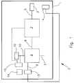
- the Fig. 1 shows a device 1 in an extracorporeal circuit 2.
- the device 1 has small-lumen cannulas 3, 4 for connection to a patient. These are shown here as single lumen cannulas but could be combined as a double lumen cannula.
- the device 1 comprises a tube system 5.
- an optional pump 7 is provided between the cannula 3 and a CO 2 -Eliminator 6 .
- the pump may be formed, for example, as a roller pump or centrifugal pump.
- an occlusive blood pump e.g. As a roller pump, be beneficial because the blood flow is largely independent of pressure ratios proportional to the pump speed. Thus, a measurement of blood flow may be unnecessary.
- the CO 2 eliminator 6 has a blood inlet 8 and a blood outlet 9. Furthermore, a gas inlet 10 and a gas outlet 11 are provided.
- the gas inlet 10 is connected to a purge gas reservoir 12, z.
- a gas blender or a gas cylinder connected as a gas line.
- At least one sensor 13 is arranged to detect parameters of the treated blood.
- the sensor 13 is connected to an evaluation device 14, which in turn is connected to a control device 15.
- various parameters of the CO 2 elimination process can be regulated as a function of the detected and evaluated parameters.
- the pump 7 can be regulated or the gas pressure of the purge gas.
- the control device 15 may be connected, for example, with a control valve between the purge gas reservoir 12 and the gas inlet 10.
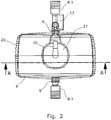
- the CO 2 -Eliminator 6 is shown in a plan view.
- a connector 8.1 is provided at the blood inlet and a connector 9.1 at the blood outlet.
- the sensor 13 is located between the blood outlet 9 and the connector 9.1.
- the sensor 13 is configured to detect temperature, blood flow, oxygen saturation, pCO 2 , pH, or other parameters of the treated blood.
- the CO 2 eliminator 6 has a housing 20. At the top of the housing a cover 21 is provided, on which the gas inlet 10 is arranged.
- the Fig. 3 shows a sectional view along the line AA of Fig. 2 ,
- a hollow fiber assembly 25 is provided which has a plurality of mats with hollow fibers.
- non-cast fibers are provided in an exchange-active region 26, while in an edge region 27 the fibers are cast and thus are not active for the gas exchange.
- the active fiber length is indicated by the letter Y, ie a dimension of the cross section which is active for the gas exchange.
- the total fiber length is X and also includes the region 27 in which the fibers are potted and thus do not participate in the gas exchange.
- the total length of the fibers is thus with X and the exchange-active fiber length or active fiber length indicated by Y.
- X the exchange-active fiber length or active fiber length indicated by Y.
- Y the exchange-active fiber length or active fiber length indicated by Y.
- the regions 28 there is inflowing purge gas and in the regions 30, 31 is gas after flowing through the hollow fiber assembly 25. From this illustration also shows that due to the arrangement of blood inlet 8 and blood outlet 9, the blood flow perpendicular to the arrangement of the fibers of the hollow fiber assembly 25 takes place.
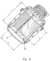
- the Fig. 4 shows a sectional view along the line BB of Fig. 3 , Here again the active fiber length Y and the entire fiber length X are shown. Furthermore, the thickness Z of the hollow fiber arrangement can be seen here.
- the thickness Z of the hollow fiber arrangement corresponds to the minimum distance of the blood passage, ie the shortest path that the blood can take through the hollow fiber arrangement.
- the blood flow takes place substantially at right angles to the orientation of the hollow fibers in the hollow fiber arrangement 25.
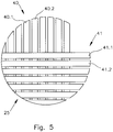
- the Fig. 5 shows a first (hollow fiber) mat 40 with a plurality of hollow fibers 40.1, 40.2, which are arranged parallel to each other. Furthermore, a second layer or mat 41 is shown with hollow fibers 41.1, 41.2, wherein the hollow fibers 41.1, 41.2 are arranged parallel to each other. However, the hollow fibers 40.1, 40.2 are arranged at right angles to the hollow fibers 41.1, 41.2. This means that the mats 40, 41 are layered crosswise.
- the purge gas supplied from the purge gas reservoir 12 enters via the input-side gas chambers 28, 29 and cut surfaces of the encapsulation in the region 27 in the hollow fibers 40.1, 40., 41.1, 41.2, passes their Inside, wherein the exchange active portion Y of the entire fiber length X causes the gas exchange. Subsequently, the gas exits at the cut surfaces of the casting in the region 27 into the outlet-side gas chambers 30, 31 and escapes via the gas outlet 11 located on the underside of the CO 2 -liminator 6.
- an exchange active surface of about 0.5 m 2 to 1.2 m 2 is sufficient.
- the exchange active hollow fibers can either be microporous or diffusive.
- This small quotient Y / Z which is not very different from 1, is the characteristic of a flow path which is optimized both on the gas side and on the gas side, and thus also for an optimized flow resistance for both media.
- the device described has the following design features: Surface for gas exchange: 1.3 m 2 Minimum active fiber length Y: 10.1 cm Total fiber length X: 12,7 cm Minimum distance of the blood passage Z 2.6 cm Maximum number of fibers 11712 Maximum number of fibers / m 2 9009
- the exchange-active fraction of the fibers is at least 79.5% and thus significantly higher than that of the device according to the invention.
- the gas exchange module at an active area of 0.98 m 2 contains at least 13119 hollow fibers or at least 13300 hollow fibers per m 2 : Surface for gas exchange: 0,98 m 2 Maximum active fiber length (Y): 5.8 cm Total fiber length (X): 7.6 cm Minimum distance of the blood passage (Z) 5,4 cm Minimum number of fibers 13119 Minimum number of fibers / m 2 13300
- This small quotient Y / Z which is not very different from 1, is the characteristic of a flow path which is optimized both on the gas side and on the gas side, and thus also for an optimized flow resistance for both media.
- the gas exchange module contains at least 17 148 hollow fibers or at least 17 497 hollow fibers per m 2 with an active area of 0.98 m 2 and use of hollow fibers at the lower limit of the specification (outer diameter 0.35 mm): Surface for gas exchange: 0,98 m 2 Maximum active fiber length (Y): 5.2 cm Total fiber length (X): 7.6 cm Minimum distance of the blood passage (Z) 5,4 cm Minimum number of fibers 17148 Minimum number of fibers / m 2 17497
- This small quotient Y / Z which is not very different from 1, is the characteristic of a flow path which is optimized both on the gas side and on the gas side, and thus also for an optimized flow resistance for both media.
Landscapes
- Health & Medical Sciences (AREA)
- Heart & Thoracic Surgery (AREA)
- Vascular Medicine (AREA)
- Anesthesiology (AREA)
- Hematology (AREA)
- Veterinary Medicine (AREA)
- Public Health (AREA)
- Engineering & Computer Science (AREA)
- General Health & Medical Sciences (AREA)
- Biomedical Technology (AREA)
- Cardiology (AREA)
- Life Sciences & Earth Sciences (AREA)
- Animal Behavior & Ethology (AREA)
- Chemical & Material Sciences (AREA)
- Chemical Kinetics & Catalysis (AREA)
- Emergency Medicine (AREA)
- Urology & Nephrology (AREA)
- Pulmonology (AREA)
- External Artificial Organs (AREA)
Priority Applications (5)
| Application Number | Priority Date | Filing Date | Title |
|---|---|---|---|
| KR1020157027326A KR102318993B1 (ko) | 2013-03-15 | 2014-03-14 | 이산화탄소 제거 시스템 |
| KR1020217034453A KR102401097B1 (ko) | 2013-03-15 | 2014-03-14 | 이산화탄소 제거 시스템 |
| PCT/IB2014/001600 WO2014177944A2 (en) | 2013-03-15 | 2014-03-14 | Carbon dioxide removal system |
| CN201480024198.5A CN105451788B (zh) | 2013-03-15 | 2014-03-14 | 二氧化碳去除系统 |
| US14/854,926 US10201649B2 (en) | 2013-03-15 | 2015-09-15 | Carbon dioxide removal system |
Applications Claiming Priority (1)
| Application Number | Priority Date | Filing Date | Title |
|---|---|---|---|
| US201361802335P | 2013-03-15 | 2013-03-15 |
Publications (3)
| Publication Number | Publication Date |
|---|---|
| EP2777801A2 EP2777801A2 (de) | 2014-09-17 |
| EP2777801A3 EP2777801A3 (de) | 2014-11-26 |
| EP2777801B1 true EP2777801B1 (de) | 2019-08-28 |
Family
ID=48444195
Family Applications (1)
| Application Number | Title | Priority Date | Filing Date |
|---|---|---|---|
| EP13168103.3A Active EP2777801B1 (de) | 2013-03-15 | 2013-05-16 | Vorrichtung zur CO2-Eliminierung von Patientenblut |
Country Status (6)
| Country | Link |
|---|---|
| US (1) | US10201649B2 (enExample) |
| EP (1) | EP2777801B1 (enExample) |
| JP (5) | JP6770803B2 (enExample) |
| KR (2) | KR102401097B1 (enExample) |
| CN (1) | CN105451788B (enExample) |
| WO (1) | WO2014177944A2 (enExample) |
Families Citing this family (15)
| Publication number | Priority date | Publication date | Assignee | Title |
|---|---|---|---|---|
| EP3090769A1 (de) * | 2015-05-07 | 2016-11-09 | Novalung GmbH | Tragbare gasaustauschvorrichtung |
| DE102016015059B4 (de) * | 2016-12-19 | 2020-11-12 | Drägerwerk AG & Co. KGaA | Vorrichtung zum extrakorporalen Blutgasaustausch |
| DE102017000940A1 (de) | 2017-02-02 | 2018-08-02 | Xenios Ag | Anordnung mit einer Blutpumpe, einer Steuereinheit und einem Gerät zur Übermittlung der Messwerte |
| DE102017131192A1 (de) | 2017-12-22 | 2019-06-27 | Fresenius Medical Care Deutschland Gmbh | Pufferlösung zur Reduzierung des Kohlendioxidgehaltes in extrakorporalem Blut |
| GB2574015A (en) * | 2018-05-22 | 2019-11-27 | Spectrum Medical Ltd | Blood processing system |
| IT201800005692A1 (it) * | 2018-05-24 | 2019-11-24 | Dispositivo per la misurazione della anidride carbonica in un gas di lavoro | |
| US11633525B2 (en) | 2019-01-29 | 2023-04-25 | Transonic Systems Inc. | Method and apparatus for assessing cardiac output in veno-arterial extracorporeal blood oxygenation |
| WO2020174013A1 (en) * | 2019-02-26 | 2020-09-03 | Obi Aps | A method for providing decision support in relation to a patient receiving oxygen treatment |
| EP4566535A3 (en) * | 2019-05-02 | 2025-06-25 | Transonic Systems Inc. | Calculating cardiac output of a patient undergoing veno-venous extracorporeal blood oxygenation |
| CA3158571A1 (en) | 2019-10-25 | 2021-04-29 | MAQUET CARDIOPULMONARY GmbH | A working fluid treatment device for mass transfer between a working fluid and two fluid exchange media |
| US12478292B2 (en) | 2019-10-28 | 2025-11-25 | The Research Foundation For The State University Of New York | Devices, systems, and methods of monitoring arterial carbon dioxide |
| USD1073948S1 (en) * | 2020-08-31 | 2025-05-06 | MAQUET CARDIOPULMONARY GmbH | Universal holder system |
| USD1002014S1 (en) * | 2020-08-31 | 2023-10-17 | MAQUET CARDIOPULMONARY GmbH | Universal holder system |
| USD1087346S1 (en) * | 2020-08-31 | 2025-08-05 | MAQUET CARDIOPULMONARY GmbH | Universal holder system |
| CN116747368A (zh) * | 2023-06-08 | 2023-09-15 | 苏州肺盾医疗科技有限公司 | 氧合器及体外膜肺氧合装置 |
Citations (1)
| Publication number | Priority date | Publication date | Assignee | Title |
|---|---|---|---|---|
| EP0521495A2 (de) * | 1991-07-05 | 1993-01-07 | Akzo Nobel N.V. | Verfahren und Vorrichtung zum Herstellen von Hohlfadenmodulen |
Family Cites Families (49)
| Publication number | Priority date | Publication date | Assignee | Title |
|---|---|---|---|---|
| GB1267105A (enExample) | 1968-12-02 | 1972-03-15 | ||
| FR2197565B1 (enExample) | 1972-08-30 | 1975-03-07 | Rhone Poulenc Ind | |
| US3890969A (en) | 1974-01-21 | 1975-06-24 | Baxter Laboratories Inc | Cardiopulmonary bypass system |
| GB1595058A (en) | 1976-10-22 | 1981-08-05 | Bellhouse Brian John | Membrane blood oxygenators |
| JPS573652A (en) | 1980-06-06 | 1982-01-09 | Kanegafuchi Chemical Ind | Artificial lung using minute hole diameter film |
| US4620965A (en) * | 1982-09-22 | 1986-11-04 | Terumo Corporation | Hollow fiber-type artificial lung |
| JPS61128978A (ja) * | 1984-11-27 | 1986-06-17 | テルモ株式会社 | 膜型人工肺 |
| US4698207A (en) | 1986-07-14 | 1987-10-06 | Baxter Travenol Laboratories, Inc. | Integrated membrane oxygenator, heat exchanger and reservoir |
| JPH0696098B2 (ja) * | 1988-05-27 | 1994-11-30 | 株式会社クラレ | 中空糸型流体処理装置 |
| JPH0724742B2 (ja) | 1988-07-25 | 1995-03-22 | テルモ株式会社 | ポリプロピレン多孔質中空糸膜およびその製造方法 |
| JPH0798061B2 (ja) * | 1989-02-13 | 1995-10-25 | 株式会社クラレ | 血液処理装置 |
| JPH03158167A (ja) * | 1989-11-15 | 1991-07-08 | Terumo Corp | 人工肺 |
| US5270005A (en) | 1990-09-07 | 1993-12-14 | Baxter International Inc. | Extracorporeal blood oxygenation system incorporating integrated reservoir-membrane oxygenerator-heat exchanger and pump assembly |
| US5480553A (en) | 1992-02-12 | 1996-01-02 | Mitsubishi Rayon Co., Ltd. | Hollow fiber membrane module |
| US5411706A (en) | 1994-02-09 | 1995-05-02 | Hubbard; Lloyd C. | Pump/oxygenator with blood recirculation |
| DE69632422T2 (de) | 1995-08-11 | 2005-05-19 | Zenon Environmental Inc., Oakville | Verfahren zum Einbetten von Hohlfaser-Membranen |
| US6866755B2 (en) | 2001-08-01 | 2005-03-15 | Battelle Memorial Institute | Photolytic artificial lung |
| JP3803421B2 (ja) * | 1996-04-26 | 2006-08-02 | 富士システムズ株式会社 | 気体交換装置 |
| US5865789A (en) | 1997-07-23 | 1999-02-02 | Hattler; Brack G. | Percutaneous oxygenator for inducing a retrograde perfusion of oxygenated blood |
| JP4026037B2 (ja) * | 1998-09-10 | 2007-12-26 | 大日本インキ化学工業株式会社 | 中空糸膜型気液ガス交換装置及びそのガス交換方法 |
| DE20011060U1 (de) * | 2000-06-23 | 2000-09-28 | JOSTRA AG, 72145 Hirrlingen | Vorrichtung zur Unterstützung der Lungenfunktion eines Patienten |
| US20020143397A1 (en) | 2001-04-02 | 2002-10-03 | Von Segesser Ludwig K. | Compliant artificial lung for extrapulmonary gas transfer |
| US7909788B2 (en) | 2001-08-01 | 2011-03-22 | Battelle Memorial Institute | Carbon dioxide removal from whole blood by photolytic activation |
| US6682698B2 (en) * | 2001-08-23 | 2004-01-27 | Michigan Critical Care Consultants, Inc. | Apparatus for exchanging gases in a liquid |
| US20030133835A1 (en) | 2002-01-16 | 2003-07-17 | Hattler Brack G. | Intravenous oxygenator having an impeller |
| DE50309751D1 (de) | 2002-07-22 | 2008-06-12 | Novalung Gmbh | Intravenöser Oxygenator |
| DE10261575A1 (de) | 2002-12-23 | 2004-07-08 | Nova Lung Gmbh | Vorrichtung zur Kanülierung eines Blut führenden Gefäßes und deren Verwendung zur Kanülierung von Blut führenden Gefäßen |
| ITTO20030785A1 (it) | 2003-10-03 | 2005-04-04 | Mri S R L Societa Unipersonale | Unita' di filtraggio del sangue in una macchina per emofiltrazione. |
| ITFI20030256A1 (it) | 2003-10-09 | 2005-04-10 | Angela Caramuta | Dispositivo per l'eliminazione dell'anidride carbonica |
| ITFI20040025A1 (it) | 2004-02-05 | 2004-05-05 | Angela Caramuta | Dispositivo per l'eliminazione dell'anidride carbonica dal sangue ed un'apparecchiatura equipaggiata con il dispositivo medesimo |
| EP1649883A1 (en) | 2004-10-19 | 2006-04-26 | MRI S.r.l. Società Unipersonale | A CO2 removal device for removing carbon dioxide from blood or from a fluid taken from patient's cardio-circulatory system |
| EP1649882A1 (en) | 2004-10-19 | 2006-04-26 | MRI S.r.l. Società Unipersonale | A CO2 removal device for removing carbon dioxide from blood |
| AU2006242663B2 (en) * | 2005-04-21 | 2012-01-19 | Alung Technologies, Inc. | Paracorporeal respiratory assist lung |
| DE102005031582A1 (de) | 2005-07-06 | 2007-01-11 | Maquet Cardiopulmonary Ag | Vorrichtung zur Behandlung von Blut in einem extrakorporalen Blutkreislauf |
| DE102005045663A1 (de) | 2005-09-13 | 2007-03-22 | Novalung Gmbh | Vorrichtung zur Unterbrechung eines durch einen Hohlkörper fließenden Blutstroms in einem extrakorporalen Blutkreislauf |
| EP1810704B1 (en) * | 2006-01-19 | 2015-04-22 | Terumo Kabushiki Kaisha | Oxygenator |
| JP4874088B2 (ja) * | 2006-01-19 | 2012-02-08 | テルモ株式会社 | 人工肺 |
| DE102006016211A1 (de) | 2006-04-03 | 2007-10-04 | Novalung Gmbh | Kupplung für rohrförmige Elemente |
| DE102006020492A1 (de) | 2006-04-21 | 2007-10-25 | Novalung Gmbh | Verwendung von Acetylsalicylsäure (ASS) beim Einsatz einer Membranlunge |
| DE102006020494A1 (de) | 2006-04-21 | 2007-10-25 | Novalung Gmbh | Künstliches Lungensystem und dessen Verwendung |
| US8585968B2 (en) | 2006-04-21 | 2013-11-19 | Scott W. Morley | Method and system for purging moisture from an oxygenator |
| DE102006021066B4 (de) | 2006-05-05 | 2009-06-25 | Fresenius Medical Care Deutschland Gmbh | Verfahren und Vorrichtung zum Einbringen einer Vergußmasse in eine Filtervorrichtung |
| US7641795B2 (en) * | 2006-06-05 | 2010-01-05 | Celgard Llc | Membrane contactor |
| DE102006042639A1 (de) | 2006-09-01 | 2008-03-20 | Novalung Gmbh | Vorrichtung zur Kanülierung eines Blut-führenden Gefäßes |
| ITMI20070913A1 (it) | 2007-05-07 | 2008-11-08 | Antonio Pesenti | Metodo di trattamento del sangue atto ad eliminare almeno parzialmente il contenuto di anidride carbonica e relativo dispositivo. |
| DE102007038121A1 (de) | 2007-07-31 | 2009-02-05 | Novalung Gmbh | Konditionierung von Blut eines Patienten durch Gase |
| DE102008024835A1 (de) | 2008-05-23 | 2009-12-10 | Maquet Cardiopulmonary Ag | Universell anwendbares optimiertes Perfusionssystem |
| DE102008045621A1 (de) | 2008-09-03 | 2010-03-04 | Novalung Gmbh | Gastransfervorrichtung und Verwendung einer strukturierten Membran |
| DE102009008601A1 (de) | 2009-02-12 | 2010-08-19 | Novalung Gmbh | Vorrichtung zur Behandlung einer biologischen Flüssigkeit |
-
2013
- 2013-05-16 EP EP13168103.3A patent/EP2777801B1/de active Active
-
2014
- 2014-03-14 KR KR1020217034453A patent/KR102401097B1/ko active Active
- 2014-03-14 WO PCT/IB2014/001600 patent/WO2014177944A2/en not_active Ceased
- 2014-03-14 JP JP2015562424A patent/JP6770803B2/ja active Active
- 2014-03-14 CN CN201480024198.5A patent/CN105451788B/zh active Active
- 2014-03-14 KR KR1020157027326A patent/KR102318993B1/ko active Active
-
2015
- 2015-09-15 US US14/854,926 patent/US10201649B2/en active Active
-
2018
- 2018-05-28 JP JP2018101363A patent/JP2018158122A/ja active Pending
-
2019
- 2019-02-21 JP JP2019029444A patent/JP7232664B2/ja active Active
- 2019-11-01 JP JP2019199802A patent/JP2020014939A/ja not_active Withdrawn
-
2021
- 2021-09-22 JP JP2021153919A patent/JP2021191539A/ja active Pending
Patent Citations (1)
| Publication number | Priority date | Publication date | Assignee | Title |
|---|---|---|---|---|
| EP0521495A2 (de) * | 1991-07-05 | 1993-01-07 | Akzo Nobel N.V. | Verfahren und Vorrichtung zum Herstellen von Hohlfadenmodulen |
Also Published As
| Publication number | Publication date |
|---|---|
| JP2016525894A (ja) | 2016-09-01 |
| JP6770803B2 (ja) | 2020-10-21 |
| EP2777801A2 (de) | 2014-09-17 |
| CN105451788B (zh) | 2018-08-10 |
| US10201649B2 (en) | 2019-02-12 |
| EP2777801A3 (de) | 2014-11-26 |
| JP2021191539A (ja) | 2021-12-16 |
| KR102318993B1 (ko) | 2021-10-28 |
| WO2014177944A2 (en) | 2014-11-06 |
| JP2019072611A (ja) | 2019-05-16 |
| KR102401097B1 (ko) | 2022-05-23 |
| WO2014177944A3 (en) | 2015-05-21 |
| JP2018158122A (ja) | 2018-10-11 |
| CN105451788A (zh) | 2016-03-30 |
| JP7232664B2 (ja) | 2023-03-03 |
| JP2020014939A (ja) | 2020-01-30 |
| US20160000989A1 (en) | 2016-01-07 |
| KR20210134982A (ko) | 2021-11-11 |
| KR20160023640A (ko) | 2016-03-03 |
| US20180236158A9 (en) | 2018-08-23 |
Similar Documents
| Publication | Publication Date | Title |
|---|---|---|
| EP2777801B1 (de) | Vorrichtung zur CO2-Eliminierung von Patientenblut | |
| EP3554578B1 (de) | Blutführungsvorrichtung zur durchführung einer extrakorporalen blutbehandlung, blutbehandlungssystem | |
| DE69009071T2 (de) | Künstliche Lunge. | |
| EP0101890B1 (de) | Doppellumiger Katheter für eine Vorrichtung zur in-vivo-Reinigung von Blut | |
| DE602004013263T2 (de) | Sensorschutzvorrichtung mit Doppelmembran | |
| EP2640439B1 (de) | Vorrichtung zur bestmöglichen erreichung des substitutionsziels bei der ultrafiltration von blut | |
| EP2533827B1 (de) | Vorrichtung und verfahren zur überwachung eines gefässzugangs für eine extrakorporale blutbehandlung | |
| EP2838579B1 (de) | Sicherheitseinrichtung für eine extrakorporale blutbehandlung | |
| EP2627368B1 (de) | Verfahren und vorrichtung zur messung und behebung von systemänderungen in einer vorrichtung zur behandlung von blut | |
| DE60037408T2 (de) | Vorrichtung zur Hämodialyse | |
| DE69733657T2 (de) | System zur vermeidung intradialytischer symptomatologie | |
| EP2714128B1 (de) | Vorrichtung und verfahren zur erkennung eines betriebszustandes einer extrakorporalen blutbehandlung | |
| EP0150462A1 (de) | Doppellumiger Katheter für eine Vorrichtung zur in-vivo-Reinigung von Blut | |
| DE102014000678A1 (de) | Vorrichtung und Verfahren zur Regelung und Vorgabe der Pumprate von Blutpumpen | |
| EP2023972A1 (de) | Vorrichtung und verfahren zur steuerung einer extrakorporalen blutbehandlungsvorrichtung | |
| DE10210009B3 (de) | Verfahren zur Bestimmung des Hämatokrit und/oder Blutvolumens und Vorrichtung zur extrakorporalen Blutbehandlung mit einer Einrichtung zur Bestimmung des Hämatokrit und/oder Blutvolumens | |
| EP2663347A1 (de) | Blutbehandlungseinheit für eine extrakorporale blutbehandlungsvorrichtung | |
| EP3090768A1 (de) | Vorrichtung mit einlassabschnitt zur behandlung einer biologischen flüssigkeit | |
| DE3422435A1 (de) | Verfahren und vorrichtung zur selektiven abtrennung pathologischer und/oder toxischer spezies aus blut oder blutplasma unter verwendung von filterkerzen | |
| DE112021006752T5 (de) | Membranoxygenator | |
| EP2825250A2 (de) | Schlauchadapter zum beeinflussen des drucks innerhalb eines schlauchabschnitts während einer medizinischen behandlung | |
| DE1566589B2 (de) | Vorrichtung zum Behandeln von Blut | |
| EP3634532B1 (de) | Vorrichtung zur extrakorporalen blutbehandlung und vorrichtung zum sammeln von blutgerinnseln | |
| EP2349394B1 (de) | Verfahren und vorrichtung zur erkennung einer paravasalen blutung | |
| EP2291210A1 (de) | Universell anwendbares optimiertes perfusionssystem |
Legal Events
| Date | Code | Title | Description |
|---|---|---|---|
| PUAI | Public reference made under article 153(3) epc to a published international application that has entered the european phase |
Free format text: ORIGINAL CODE: 0009012 |
|
| 17P | Request for examination filed |
Effective date: 20130516 |
|
| AK | Designated contracting states |
Kind code of ref document: A2 Designated state(s): AL AT BE BG CH CY CZ DE DK EE ES FI FR GB GR HR HU IE IS IT LI LT LU LV MC MK MT NL NO PL PT RO RS SE SI SK SM TR |
|
| AX | Request for extension of the european patent |
Extension state: BA ME |
|
| PUAL | Search report despatched |
Free format text: ORIGINAL CODE: 0009013 |
|
| AK | Designated contracting states |
Kind code of ref document: A3 Designated state(s): AL AT BE BG CH CY CZ DE DK EE ES FI FR GB GR HR HU IE IS IT LI LT LU LV MC MK MT NL NO PL PT RO RS SE SI SK SM TR |
|
| AX | Request for extension of the european patent |
Extension state: BA ME |
|
| RIC1 | Information provided on ipc code assigned before grant |
Ipc: A61M 1/16 20060101ALI20141021BHEP Ipc: B01D 63/02 20060101AFI20141021BHEP Ipc: A61M 1/36 20060101ALI20141021BHEP Ipc: B01D 19/00 20060101ALI20141021BHEP |
|
| R17P | Request for examination filed (corrected) |
Effective date: 20150526 |
|
| RBV | Designated contracting states (corrected) |
Designated state(s): AL AT BE BG CH CY CZ DE DK EE ES FI FR GB GR HR HU IE IS IT LI LT LU LV MC MK MT NL NO PL PT RO RS SE SI SK SM TR |
|
| STAA | Information on the status of an ep patent application or granted ep patent |
Free format text: STATUS: EXAMINATION IS IN PROGRESS |
|
| 17Q | First examination report despatched |
Effective date: 20170920 |
|
| GRAP | Despatch of communication of intention to grant a patent |
Free format text: ORIGINAL CODE: EPIDOSNIGR1 |
|
| STAA | Information on the status of an ep patent application or granted ep patent |
Free format text: STATUS: GRANT OF PATENT IS INTENDED |
|
| INTG | Intention to grant announced |
Effective date: 20190322 |
|
| INTG | Intention to grant announced |
Effective date: 20190322 |
|
| GRAS | Grant fee paid |
Free format text: ORIGINAL CODE: EPIDOSNIGR3 |
|
| GRAA | (expected) grant |
Free format text: ORIGINAL CODE: 0009210 |
|
| STAA | Information on the status of an ep patent application or granted ep patent |
Free format text: STATUS: THE PATENT HAS BEEN GRANTED |
|
| AK | Designated contracting states |
Kind code of ref document: B1 Designated state(s): AL AT BE BG CH CY CZ DE DK EE ES FI FR GB GR HR HU IE IS IT LI LT LU LV MC MK MT NL NO PL PT RO RS SE SI SK SM TR |
|
| REG | Reference to a national code |
Ref country code: GB Ref legal event code: FG4D Free format text: NOT ENGLISH |
|
| REG | Reference to a national code |
Ref country code: CH Ref legal event code: EP |
|
| REG | Reference to a national code |
Ref country code: AT Ref legal event code: REF Ref document number: 1171673 Country of ref document: AT Kind code of ref document: T Effective date: 20190915 |
|
| REG | Reference to a national code |
Ref country code: IE Ref legal event code: FG4D Free format text: LANGUAGE OF EP DOCUMENT: GERMAN |
|
| REG | Reference to a national code |
Ref country code: DE Ref legal event code: R096 Ref document number: 502013013448 Country of ref document: DE |
|
| RAP2 | Party data changed (patent owner data changed or rights of a patent transferred) |
Owner name: MAQUET CARDIOPULMONARY GMBH |
|
| REG | Reference to a national code |
Ref country code: NL Ref legal event code: MP Effective date: 20190828 |
|
| REG | Reference to a national code |
Ref country code: LT Ref legal event code: MG4D |
|
| PG25 | Lapsed in a contracting state [announced via postgrant information from national office to epo] |
Ref country code: NO Free format text: LAPSE BECAUSE OF FAILURE TO SUBMIT A TRANSLATION OF THE DESCRIPTION OR TO PAY THE FEE WITHIN THE PRESCRIBED TIME-LIMIT Effective date: 20191128 Ref country code: SE Free format text: LAPSE BECAUSE OF FAILURE TO SUBMIT A TRANSLATION OF THE DESCRIPTION OR TO PAY THE FEE WITHIN THE PRESCRIBED TIME-LIMIT Effective date: 20190828 Ref country code: PT Free format text: LAPSE BECAUSE OF FAILURE TO SUBMIT A TRANSLATION OF THE DESCRIPTION OR TO PAY THE FEE WITHIN THE PRESCRIBED TIME-LIMIT Effective date: 20191230 Ref country code: FI Free format text: LAPSE BECAUSE OF FAILURE TO SUBMIT A TRANSLATION OF THE DESCRIPTION OR TO PAY THE FEE WITHIN THE PRESCRIBED TIME-LIMIT Effective date: 20190828 Ref country code: HR Free format text: LAPSE BECAUSE OF FAILURE TO SUBMIT A TRANSLATION OF THE DESCRIPTION OR TO PAY THE FEE WITHIN THE PRESCRIBED TIME-LIMIT Effective date: 20190828 Ref country code: LT Free format text: LAPSE BECAUSE OF FAILURE TO SUBMIT A TRANSLATION OF THE DESCRIPTION OR TO PAY THE FEE WITHIN THE PRESCRIBED TIME-LIMIT Effective date: 20190828 Ref country code: NL Free format text: LAPSE BECAUSE OF FAILURE TO SUBMIT A TRANSLATION OF THE DESCRIPTION OR TO PAY THE FEE WITHIN THE PRESCRIBED TIME-LIMIT Effective date: 20190828 Ref country code: BG Free format text: LAPSE BECAUSE OF FAILURE TO SUBMIT A TRANSLATION OF THE DESCRIPTION OR TO PAY THE FEE WITHIN THE PRESCRIBED TIME-LIMIT Effective date: 20191128 |
|
| PG25 | Lapsed in a contracting state [announced via postgrant information from national office to epo] |
Ref country code: ES Free format text: LAPSE BECAUSE OF FAILURE TO SUBMIT A TRANSLATION OF THE DESCRIPTION OR TO PAY THE FEE WITHIN THE PRESCRIBED TIME-LIMIT Effective date: 20190828 Ref country code: AL Free format text: LAPSE BECAUSE OF FAILURE TO SUBMIT A TRANSLATION OF THE DESCRIPTION OR TO PAY THE FEE WITHIN THE PRESCRIBED TIME-LIMIT Effective date: 20190828 Ref country code: GR Free format text: LAPSE BECAUSE OF FAILURE TO SUBMIT A TRANSLATION OF THE DESCRIPTION OR TO PAY THE FEE WITHIN THE PRESCRIBED TIME-LIMIT Effective date: 20191129 Ref country code: LV Free format text: LAPSE BECAUSE OF FAILURE TO SUBMIT A TRANSLATION OF THE DESCRIPTION OR TO PAY THE FEE WITHIN THE PRESCRIBED TIME-LIMIT Effective date: 20190828 Ref country code: RS Free format text: LAPSE BECAUSE OF FAILURE TO SUBMIT A TRANSLATION OF THE DESCRIPTION OR TO PAY THE FEE WITHIN THE PRESCRIBED TIME-LIMIT Effective date: 20190828 Ref country code: IS Free format text: LAPSE BECAUSE OF FAILURE TO SUBMIT A TRANSLATION OF THE DESCRIPTION OR TO PAY THE FEE WITHIN THE PRESCRIBED TIME-LIMIT Effective date: 20191228 |
|
| PG25 | Lapsed in a contracting state [announced via postgrant information from national office to epo] |
Ref country code: TR Free format text: LAPSE BECAUSE OF FAILURE TO SUBMIT A TRANSLATION OF THE DESCRIPTION OR TO PAY THE FEE WITHIN THE PRESCRIBED TIME-LIMIT Effective date: 20190828 |
|
| PG25 | Lapsed in a contracting state [announced via postgrant information from national office to epo] |
Ref country code: PL Free format text: LAPSE BECAUSE OF FAILURE TO SUBMIT A TRANSLATION OF THE DESCRIPTION OR TO PAY THE FEE WITHIN THE PRESCRIBED TIME-LIMIT Effective date: 20190828 Ref country code: RO Free format text: LAPSE BECAUSE OF FAILURE TO SUBMIT A TRANSLATION OF THE DESCRIPTION OR TO PAY THE FEE WITHIN THE PRESCRIBED TIME-LIMIT Effective date: 20190828 Ref country code: DK Free format text: LAPSE BECAUSE OF FAILURE TO SUBMIT A TRANSLATION OF THE DESCRIPTION OR TO PAY THE FEE WITHIN THE PRESCRIBED TIME-LIMIT Effective date: 20190828 Ref country code: EE Free format text: LAPSE BECAUSE OF FAILURE TO SUBMIT A TRANSLATION OF THE DESCRIPTION OR TO PAY THE FEE WITHIN THE PRESCRIBED TIME-LIMIT Effective date: 20190828 Ref country code: IT Free format text: LAPSE BECAUSE OF FAILURE TO SUBMIT A TRANSLATION OF THE DESCRIPTION OR TO PAY THE FEE WITHIN THE PRESCRIBED TIME-LIMIT Effective date: 20190828 |
|
| PG25 | Lapsed in a contracting state [announced via postgrant information from national office to epo] |
Ref country code: IS Free format text: LAPSE BECAUSE OF FAILURE TO SUBMIT A TRANSLATION OF THE DESCRIPTION OR TO PAY THE FEE WITHIN THE PRESCRIBED TIME-LIMIT Effective date: 20200224 Ref country code: CZ Free format text: LAPSE BECAUSE OF FAILURE TO SUBMIT A TRANSLATION OF THE DESCRIPTION OR TO PAY THE FEE WITHIN THE PRESCRIBED TIME-LIMIT Effective date: 20190828 Ref country code: SM Free format text: LAPSE BECAUSE OF FAILURE TO SUBMIT A TRANSLATION OF THE DESCRIPTION OR TO PAY THE FEE WITHIN THE PRESCRIBED TIME-LIMIT Effective date: 20190828 Ref country code: SK Free format text: LAPSE BECAUSE OF FAILURE TO SUBMIT A TRANSLATION OF THE DESCRIPTION OR TO PAY THE FEE WITHIN THE PRESCRIBED TIME-LIMIT Effective date: 20190828 |
|
| REG | Reference to a national code |
Ref country code: DE Ref legal event code: R097 Ref document number: 502013013448 Country of ref document: DE |
|
| PLBE | No opposition filed within time limit |
Free format text: ORIGINAL CODE: 0009261 |
|
| STAA | Information on the status of an ep patent application or granted ep patent |
Free format text: STATUS: NO OPPOSITION FILED WITHIN TIME LIMIT |
|
| PG2D | Information on lapse in contracting state deleted |
Ref country code: IS |
|
| 26N | No opposition filed |
Effective date: 20200603 |
|
| PG25 | Lapsed in a contracting state [announced via postgrant information from national office to epo] |
Ref country code: SI Free format text: LAPSE BECAUSE OF FAILURE TO SUBMIT A TRANSLATION OF THE DESCRIPTION OR TO PAY THE FEE WITHIN THE PRESCRIBED TIME-LIMIT Effective date: 20190828 |
|
| PG25 | Lapsed in a contracting state [announced via postgrant information from national office to epo] |
Ref country code: MC Free format text: LAPSE BECAUSE OF FAILURE TO SUBMIT A TRANSLATION OF THE DESCRIPTION OR TO PAY THE FEE WITHIN THE PRESCRIBED TIME-LIMIT Effective date: 20190828 Ref country code: LI Free format text: LAPSE BECAUSE OF NON-PAYMENT OF DUE FEES Effective date: 20200531 Ref country code: CH Free format text: LAPSE BECAUSE OF NON-PAYMENT OF DUE FEES Effective date: 20200531 |
|
| REG | Reference to a national code |
Ref country code: BE Ref legal event code: MM Effective date: 20200531 |
|
| PG25 | Lapsed in a contracting state [announced via postgrant information from national office to epo] |
Ref country code: LU Free format text: LAPSE BECAUSE OF NON-PAYMENT OF DUE FEES Effective date: 20200516 |
|
| PG25 | Lapsed in a contracting state [announced via postgrant information from national office to epo] |
Ref country code: IE Free format text: LAPSE BECAUSE OF NON-PAYMENT OF DUE FEES Effective date: 20200516 |
|
| PG25 | Lapsed in a contracting state [announced via postgrant information from national office to epo] |
Ref country code: BE Free format text: LAPSE BECAUSE OF NON-PAYMENT OF DUE FEES Effective date: 20200531 |
|
| REG | Reference to a national code |
Ref country code: AT Ref legal event code: MM01 Ref document number: 1171673 Country of ref document: AT Kind code of ref document: T Effective date: 20200516 |
|
| PG25 | Lapsed in a contracting state [announced via postgrant information from national office to epo] |
Ref country code: AT Free format text: LAPSE BECAUSE OF NON-PAYMENT OF DUE FEES Effective date: 20200516 |
|
| PG25 | Lapsed in a contracting state [announced via postgrant information from national office to epo] |
Ref country code: MT Free format text: LAPSE BECAUSE OF FAILURE TO SUBMIT A TRANSLATION OF THE DESCRIPTION OR TO PAY THE FEE WITHIN THE PRESCRIBED TIME-LIMIT Effective date: 20190828 Ref country code: CY Free format text: LAPSE BECAUSE OF FAILURE TO SUBMIT A TRANSLATION OF THE DESCRIPTION OR TO PAY THE FEE WITHIN THE PRESCRIBED TIME-LIMIT Effective date: 20190828 |
|
| PG25 | Lapsed in a contracting state [announced via postgrant information from national office to epo] |
Ref country code: MK Free format text: LAPSE BECAUSE OF FAILURE TO SUBMIT A TRANSLATION OF THE DESCRIPTION OR TO PAY THE FEE WITHIN THE PRESCRIBED TIME-LIMIT Effective date: 20190828 |
|
| REG | Reference to a national code |
Ref country code: DE Ref legal event code: R082 Ref document number: 502013013448 Country of ref document: DE Representative=s name: HOEFER & PARTNER PATENTANWAELTE MBB, DE |
|
| REG | Reference to a national code |
Ref country code: FR Ref legal event code: PLFP Year of fee payment: 11 |
|
| P01 | Opt-out of the competence of the unified patent court (upc) registered |
Effective date: 20230630 |
|
| PGFP | Annual fee paid to national office [announced via postgrant information from national office to epo] |
Ref country code: DE Payment date: 20250423 Year of fee payment: 13 |
|
| PGFP | Annual fee paid to national office [announced via postgrant information from national office to epo] |
Ref country code: GB Payment date: 20250423 Year of fee payment: 13 |
|
| PGFP | Annual fee paid to national office [announced via postgrant information from national office to epo] |
Ref country code: FR Payment date: 20250423 Year of fee payment: 13 |