EP2776140B1 - Materiau filtrant et element filtrant - Google Patents
Materiau filtrant et element filtrant Download PDFInfo
- Publication number
- EP2776140B1 EP2776140B1 EP12786945.1A EP12786945A EP2776140B1 EP 2776140 B1 EP2776140 B1 EP 2776140B1 EP 12786945 A EP12786945 A EP 12786945A EP 2776140 B1 EP2776140 B1 EP 2776140B1
- Authority
- EP
- European Patent Office
- Prior art keywords
- filter material
- layer
- filter
- fine
- material according
- Prior art date
- Legal status (The legal status is an assumption and is not a legal conclusion. Google has not performed a legal analysis and makes no representation as to the accuracy of the status listed.)
- Active
Links
- 239000000463 material Substances 0.000 title claims description 67
- 239000010410 layer Substances 0.000 claims description 164
- 239000000835 fiber Substances 0.000 claims description 84
- 239000011148 porous material Substances 0.000 claims description 58
- 238000005470 impregnation Methods 0.000 claims description 20
- 229920005989 resin Polymers 0.000 claims description 12
- 239000011347 resin Substances 0.000 claims description 12
- 239000004952 Polyamide Substances 0.000 claims description 8
- 229920002678 cellulose Polymers 0.000 claims description 8
- 239000001913 cellulose Substances 0.000 claims description 8
- 229920002647 polyamide Polymers 0.000 claims description 8
- 230000035699 permeability Effects 0.000 claims description 7
- 239000004698 Polyethylene Substances 0.000 claims description 6
- 239000004743 Polypropylene Substances 0.000 claims description 6
- -1 polyethylene Polymers 0.000 claims description 6
- 229920000573 polyethylene Polymers 0.000 claims description 6
- 229920001155 polypropylene Polymers 0.000 claims description 6
- 238000011144 upstream manufacturing Methods 0.000 claims description 6
- 238000004132 cross linking Methods 0.000 claims description 4
- 150000001252 acrylic acid derivatives Chemical class 0.000 claims description 3
- 238000002485 combustion reaction Methods 0.000 claims description 3
- 239000003822 epoxy resin Substances 0.000 claims description 3
- LNEPOXFFQSENCJ-UHFFFAOYSA-N haloperidol Chemical compound C1CC(O)(C=2C=CC(Cl)=CC=2)CCN1CCCC(=O)C1=CC=C(F)C=C1 LNEPOXFFQSENCJ-UHFFFAOYSA-N 0.000 claims description 3
- 229920001568 phenolic resin Polymers 0.000 claims description 3
- 239000005011 phenolic resin Substances 0.000 claims description 3
- 229920000647 polyepoxide Polymers 0.000 claims description 3
- 229920000728 polyester Polymers 0.000 claims description 3
- 239000012790 adhesive layer Substances 0.000 claims description 2
- 230000000694 effects Effects 0.000 claims description 2
- 229920002994 synthetic fiber Polymers 0.000 claims description 2
- 239000000758 substrate Substances 0.000 claims 9
- 239000004071 soot Substances 0.000 description 17
- 238000010521 absorption reaction Methods 0.000 description 16
- 238000000926 separation method Methods 0.000 description 15
- 230000001070 adhesive effect Effects 0.000 description 12
- 239000000853 adhesive Substances 0.000 description 11
- 239000002245 particle Substances 0.000 description 8
- 239000002131 composite material Substances 0.000 description 6
- 238000011068 loading method Methods 0.000 description 4
- 239000003921 oil Substances 0.000 description 4
- 229920000642 polymer Polymers 0.000 description 4
- RNFJDJUURJAICM-UHFFFAOYSA-N 2,2,4,4,6,6-hexaphenoxy-1,3,5-triaza-2$l^{5},4$l^{5},6$l^{5}-triphosphacyclohexa-1,3,5-triene Chemical compound N=1P(OC=2C=CC=CC=2)(OC=2C=CC=CC=2)=NP(OC=2C=CC=CC=2)(OC=2C=CC=CC=2)=NP=1(OC=1C=CC=CC=1)OC1=CC=CC=C1 RNFJDJUURJAICM-UHFFFAOYSA-N 0.000 description 3
- 239000012876 carrier material Substances 0.000 description 3
- 150000001875 compounds Chemical class 0.000 description 3
- 239000003063 flame retardant Substances 0.000 description 3
- 239000000446 fuel Substances 0.000 description 3
- 239000002121 nanofiber Substances 0.000 description 3
- 238000003860 storage Methods 0.000 description 3
- 230000006835 compression Effects 0.000 description 2
- 238000007906 compression Methods 0.000 description 2
- 230000001419 dependent effect Effects 0.000 description 2
- 238000009826 distribution Methods 0.000 description 2
- 238000001914 filtration Methods 0.000 description 2
- 239000002904 solvent Substances 0.000 description 2
- 125000006850 spacer group Chemical group 0.000 description 2
- 239000000126 substance Substances 0.000 description 2
- 238000003466 welding Methods 0.000 description 2
- 238000004804 winding Methods 0.000 description 2
- 239000003570 air Substances 0.000 description 1
- 230000015572 biosynthetic process Effects 0.000 description 1
- 238000004140 cleaning Methods 0.000 description 1
- 238000001816 cooling Methods 0.000 description 1
- 230000008021 deposition Effects 0.000 description 1
- 239000004744 fabric Substances 0.000 description 1
- 238000011049 filling Methods 0.000 description 1
- 239000012530 fluid Substances 0.000 description 1
- 239000003365 glass fiber Substances 0.000 description 1
- 230000002427 irreversible effect Effects 0.000 description 1
- 238000002955 isolation Methods 0.000 description 1
- 239000007788 liquid Substances 0.000 description 1
- 230000007774 longterm Effects 0.000 description 1
- 239000000155 melt Substances 0.000 description 1
- 239000010705 motor oil Substances 0.000 description 1
- 239000004745 nonwoven fabric Substances 0.000 description 1
- 230000035515 penetration Effects 0.000 description 1
- 239000004033 plastic Substances 0.000 description 1
- 229920003023 plastic Polymers 0.000 description 1
- 239000004814 polyurethane Substances 0.000 description 1
- 238000003825 pressing Methods 0.000 description 1
- 230000002441 reversible effect Effects 0.000 description 1
- 239000002356 single layer Substances 0.000 description 1
- 238000009987 spinning Methods 0.000 description 1
- 239000012209 synthetic fiber Substances 0.000 description 1
- 239000004753 textile Substances 0.000 description 1
- 229920001169 thermoplastic Polymers 0.000 description 1
- 239000004416 thermosoftening plastic Substances 0.000 description 1
- 238000009827 uniform distribution Methods 0.000 description 1
- XLYOFNOQVPJJNP-UHFFFAOYSA-N water Substances O XLYOFNOQVPJJNP-UHFFFAOYSA-N 0.000 description 1
Images
Classifications
-
- B—PERFORMING OPERATIONS; TRANSPORTING
- B01—PHYSICAL OR CHEMICAL PROCESSES OR APPARATUS IN GENERAL
- B01D—SEPARATION
- B01D46/00—Filters or filtering processes specially modified for separating dispersed particles from gases or vapours
- B01D46/56—Filters or filtering processes specially modified for separating dispersed particles from gases or vapours with multiple filtering elements, characterised by their mutual disposition
- B01D46/62—Filters or filtering processes specially modified for separating dispersed particles from gases or vapours with multiple filtering elements, characterised by their mutual disposition connected in series
-
- B—PERFORMING OPERATIONS; TRANSPORTING
- B01—PHYSICAL OR CHEMICAL PROCESSES OR APPARATUS IN GENERAL
- B01D—SEPARATION
- B01D39/00—Filtering material for liquid or gaseous fluids
- B01D39/14—Other self-supporting filtering material ; Other filtering material
- B01D39/16—Other self-supporting filtering material ; Other filtering material of organic material, e.g. synthetic fibres
- B01D39/1607—Other self-supporting filtering material ; Other filtering material of organic material, e.g. synthetic fibres the material being fibrous
- B01D39/1623—Other self-supporting filtering material ; Other filtering material of organic material, e.g. synthetic fibres the material being fibrous of synthetic origin
- B01D39/163—Other self-supporting filtering material ; Other filtering material of organic material, e.g. synthetic fibres the material being fibrous of synthetic origin sintered or bonded
-
- B—PERFORMING OPERATIONS; TRANSPORTING
- B01—PHYSICAL OR CHEMICAL PROCESSES OR APPARATUS IN GENERAL
- B01D—SEPARATION
- B01D39/00—Filtering material for liquid or gaseous fluids
- B01D39/14—Other self-supporting filtering material ; Other filtering material
- B01D39/16—Other self-supporting filtering material ; Other filtering material of organic material, e.g. synthetic fibres
- B01D39/18—Other self-supporting filtering material ; Other filtering material of organic material, e.g. synthetic fibres the material being cellulose or derivatives thereof
-
- B—PERFORMING OPERATIONS; TRANSPORTING
- B01—PHYSICAL OR CHEMICAL PROCESSES OR APPARATUS IN GENERAL
- B01D—SEPARATION
- B01D46/00—Filters or filtering processes specially modified for separating dispersed particles from gases or vapours
- B01D46/52—Particle separators, e.g. dust precipitators, using filters embodying folded corrugated or wound sheet material
- B01D46/521—Particle separators, e.g. dust precipitators, using filters embodying folded corrugated or wound sheet material using folded, pleated material
-
- B—PERFORMING OPERATIONS; TRANSPORTING
- B01—PHYSICAL OR CHEMICAL PROCESSES OR APPARATUS IN GENERAL
- B01D—SEPARATION
- B01D46/00—Filters or filtering processes specially modified for separating dispersed particles from gases or vapours
- B01D46/52—Particle separators, e.g. dust precipitators, using filters embodying folded corrugated or wound sheet material
- B01D46/528—Particle separators, e.g. dust precipitators, using filters embodying folded corrugated or wound sheet material using wound sheets
-
- F—MECHANICAL ENGINEERING; LIGHTING; HEATING; WEAPONS; BLASTING
- F02—COMBUSTION ENGINES; HOT-GAS OR COMBUSTION-PRODUCT ENGINE PLANTS
- F02M—SUPPLYING COMBUSTION ENGINES IN GENERAL WITH COMBUSTIBLE MIXTURES OR CONSTITUENTS THEREOF
- F02M35/00—Combustion-air cleaners, air intakes, intake silencers, or induction systems specially adapted for, or arranged on, internal-combustion engines
- F02M35/02—Air cleaners
- F02M35/08—Air cleaners with means for removing dust, particles or liquids from cleaners; with means for indicating clogging; with by-pass means; Regeneration of cleaners
-
- B—PERFORMING OPERATIONS; TRANSPORTING
- B01—PHYSICAL OR CHEMICAL PROCESSES OR APPARATUS IN GENERAL
- B01D—SEPARATION
- B01D2239/00—Aspects relating to filtering material for liquid or gaseous fluids
- B01D2239/04—Additives and treatments of the filtering material
- B01D2239/0464—Impregnants
-
- B—PERFORMING OPERATIONS; TRANSPORTING
- B01—PHYSICAL OR CHEMICAL PROCESSES OR APPARATUS IN GENERAL
- B01D—SEPARATION
- B01D2239/00—Aspects relating to filtering material for liquid or gaseous fluids
- B01D2239/06—Filter cloth, e.g. knitted, woven non-woven; self-supported material
- B01D2239/0604—Arrangement of the fibres in the filtering material
- B01D2239/0622—Melt-blown
-
- B—PERFORMING OPERATIONS; TRANSPORTING
- B01—PHYSICAL OR CHEMICAL PROCESSES OR APPARATUS IN GENERAL
- B01D—SEPARATION
- B01D2239/00—Aspects relating to filtering material for liquid or gaseous fluids
- B01D2239/06—Filter cloth, e.g. knitted, woven non-woven; self-supported material
- B01D2239/0604—Arrangement of the fibres in the filtering material
- B01D2239/0636—Two or more types of fibres present in the filter material
-
- B—PERFORMING OPERATIONS; TRANSPORTING
- B01—PHYSICAL OR CHEMICAL PROCESSES OR APPARATUS IN GENERAL
- B01D—SEPARATION
- B01D2239/00—Aspects relating to filtering material for liquid or gaseous fluids
- B01D2239/06—Filter cloth, e.g. knitted, woven non-woven; self-supported material
- B01D2239/065—More than one layer present in the filtering material
- B01D2239/0654—Support layers
-
- B—PERFORMING OPERATIONS; TRANSPORTING
- B01—PHYSICAL OR CHEMICAL PROCESSES OR APPARATUS IN GENERAL
- B01D—SEPARATION
- B01D2239/00—Aspects relating to filtering material for liquid or gaseous fluids
- B01D2239/06—Filter cloth, e.g. knitted, woven non-woven; self-supported material
- B01D2239/065—More than one layer present in the filtering material
- B01D2239/0681—The layers being joined by gluing
-
- B—PERFORMING OPERATIONS; TRANSPORTING
- B01—PHYSICAL OR CHEMICAL PROCESSES OR APPARATUS IN GENERAL
- B01D—SEPARATION
- B01D2239/00—Aspects relating to filtering material for liquid or gaseous fluids
- B01D2239/06—Filter cloth, e.g. knitted, woven non-woven; self-supported material
- B01D2239/069—Special geometry of layers
- B01D2239/0695—Wound layers
-
- B—PERFORMING OPERATIONS; TRANSPORTING
- B01—PHYSICAL OR CHEMICAL PROCESSES OR APPARATUS IN GENERAL
- B01D—SEPARATION
- B01D2239/00—Aspects relating to filtering material for liquid or gaseous fluids
- B01D2239/12—Special parameters characterising the filtering material
- B01D2239/1208—Porosity
-
- B—PERFORMING OPERATIONS; TRANSPORTING
- B01—PHYSICAL OR CHEMICAL PROCESSES OR APPARATUS IN GENERAL
- B01D—SEPARATION
- B01D2239/00—Aspects relating to filtering material for liquid or gaseous fluids
- B01D2239/12—Special parameters characterising the filtering material
- B01D2239/1216—Pore size
-
- B—PERFORMING OPERATIONS; TRANSPORTING
- B01—PHYSICAL OR CHEMICAL PROCESSES OR APPARATUS IN GENERAL
- B01D—SEPARATION
- B01D2275/00—Filter media structures for filters specially adapted for separating dispersed particles from gases or vapours
- B01D2275/10—Multiple layers
-
- B—PERFORMING OPERATIONS; TRANSPORTING
- B01—PHYSICAL OR CHEMICAL PROCESSES OR APPARATUS IN GENERAL
- B01D—SEPARATION
- B01D2275/00—Filter media structures for filters specially adapted for separating dispersed particles from gases or vapours
- B01D2275/10—Multiple layers
- B01D2275/105—Wound layers
-
- B—PERFORMING OPERATIONS; TRANSPORTING
- B01—PHYSICAL OR CHEMICAL PROCESSES OR APPARATUS IN GENERAL
- B01D—SEPARATION
- B01D2275/00—Filter media structures for filters specially adapted for separating dispersed particles from gases or vapours
- B01D2275/30—Porosity of filtering material
- B01D2275/305—Porosity decreasing in flow direction
Definitions
- the present invention relates to a filter material, in particular for an air filter, according to the preamble of claim 1.
- WO 2011/110637 A2 is a generic filter medium of a filter element for filtering a fluid, in particular a liquid fuel, water, engine oil or air, known, comprising at least one nonwoven filter layer of synthetic single fibers.
- the filter medium has an increasing degree of separation in the direction of flow for the particles to be filtered out.
- the filter layer also has an increasing in the direction of flow compression.
- a filter material comprising at least one carrier material layer and at least one nonwoven fabric layer known.
- the at least one fiber fleece layer has a nanofiber nonwoven layer with an average fiber diameter of 10 to 1000 nanometers and further nanofiber-specific parameters.
- the carrier material layer is constructed from a filter paper.
- a multilayered filter material having a fibrous layer laminated together with a paper support layer. Also from the EP 1 366 791 Such a filter material is known, wherein the carrier layer is impregnated with a resin.
- the present invention is concerned with the problem of providing for a filter material of the generic type an improved or at least one alternative embodiment, which is characterized in particular by a high soot absorption capacity and a high separation efficiency.
- the present invention is based on the general idea of providing a degressive pore size in the case of a filter material in the direction of flow, which is realized by connecting an inflow-side carrier layer of the filter material and a downstream fine-fiber layer to one another via an intermediate connecting region.
- an impregnation is applied to the inflow side of the carrier layer.
- the support layer arranged on the inflow side is designed as an open cellulosic layer.
- the carrier layer is made thick in relation to the entire filter material.
- the thickness of the carrier layer has a proportion of greater than 75%, preferably greater than 80% of the thickness of the overall composite.
- the thickness of the carrier layer is about 0.3 mm to 1.0 mm, preferably about 0.60 mm to 0.65 mm.
- the thickness of the carrier layer is determined at 0.5 kPa measuring pressure.
- a not further processed carrier layer is considered.
- the thickness of the carrier layer can be reduced in various processing steps, for example by winding, folding, or calibrating.
- the carrier layer has many open pores.
- the carrier layer offers a high soot absorption capacity due to the open pores and the large carrier layer thickness.
- a fine fiber layer is applied downstream of the carrier layer.
- the fine fiber layer which may be formed, for example, as a so-called meltblown layer, has a high degree of separation but only a low soot absorption capacity.
- the fine fiber layer has a small thickness of max. 25%, in particular 20%, proportion of the thickness of the entire composite.
- the thickness of the fine fiber layer may be about 0.15 mm to 0.23 mm, preferably about 0.19 mm.
- the thickness of the fine fiber layer is also determined at 0.5 kPa measuring pressure.
- a not further processed fine fiber layer is considered.
- the thickness of the fine fiber layer can be reduced in various processing steps, for example by winding, folding, or calibrating. Especially It is possible that the fine fiber layer in subsequent processing steps or workflows by a significant proportion may be more than 50%, compressed. This compression can be reversible or irreversible, especially under the action of heat.
- the respective advantages of the two layers namely the high soot absorption capacity of the carrier layer combined with the same high separation efficiency of the fine fiber layer and thereby creating a filter material that is loaded evenly over the entire depth. Due to the uniform loading of the filter material to be prevented in particular that the dirt holding capacity of a filter layer is exhausted before the other.
- the soot absorption capacity referred to for the first time and subsequently in this paragraph is generally representative of the absorption capacity for particles to be filtered out.
- the uniform loading with simultaneously extremely high filter capacity is also ensured by the narrowing in the flow direction pore size.
- the predetermined thickness of at least 0.35 mm, preferably 0.5-1.0 mm, ensures the long-term high filter performance of the filter material according to the invention.
- a filter material for example in pleated filter elements, which are annular closed or flat, but also in wound inserts with mutually closed channels, in particular for cleaning the intake air of an internal combustion engine.
- the carrier layer which is also flame retardant, has the impregnation according to the invention.
- a cellulosic material for such a carrier layer consists of 22% by mass of a resin which contributes to the strength, rigidity, dimensional stability (in particular of embossed spacers / cams) as well as protection from external influencing factors (moisture, moisture, chemicals such as oil, fuel).
- a smearing of very fine pores (on the outflow side) and a closing or shrinking of finer ones can occur Pores are reduced by a gapping of the resin, so that the pore structure is only marginally changed by the resin on the clean side, that is, the downstream side of the support layer and on the upstream side, that is on the raw side. Also, the resin content in the carrier layer, which is reduced in comparison with conventional resin contents (25-27% by mass), can reduce the smearing of very fine pores, which are located in particular on the downstream side of a cellulose paper.
- the impregnation contributes significantly to an advantageous degressive distribution of the pores in the flow direction according to the invention while avoiding sudden pore size changes.
- both the separation efficiency and the dirt storage capacity in particular for the application of soot particles, which penetrate particularly deep into the filter material due to their fineness, increased.
- the impregnation may be in the form of a curable impregnation which forms a crosslinking under the influence of heat or as a non-curable impregnation. Furthermore, it may include phenolic resins, acrylates or epoxy resins.
- the pores of the carrier layer have a pore diameter of between 65 and 85 ⁇ m, in particular a pore diameter of approximately 74 ⁇ m. Preferably, 40 to 80% of the pores are in the range of a pore diameter of about 65 to 85 microns, whereby a relatively open-pored carrier layer can be achieved with a high air permeability and a high soot absorption capacity.
- the carrier layer is, for example, cellulose with or without art fiber content in question.
- the cellulose layer can be made weldable, for example.
- An addition of glass fibers in the cellulose causes a higher capacity of the filter medium, since the porosity can be made larger.
- the impregnation of the invention can not only improve the flame retardancy, but also positively influence the material stability.
- embossed structures such as e.g. Grooves or creases for pleat spacing, higher dimensional stability.
- hardenable impregnations which form a crosslinking under the action of heat, or non-hardenable impregnations (NC: non-curing), which are self-crosslinking even without the action of heat, can be used.
- Suitable impregnations are, for example, phenolic resins, acrylates or epoxy resins.
- the pores of the fine fiber layer may have a pore diameter between 30 and 40 microns, wherein also about 40 to 80% of the pores are in this range. Due to the comparatively very small pore size, the fine fiber layer has a low soot absorption capacity, but a comparatively high degree of separation.
- the fibers of the fine fiber layer can be formed, for example, from polyamide (PA), from polyethylene (PE), polyester or from polypropylene (PP), it being understood that sheathed or entirely different fibers are conceivable.
- a fiber diameter of the fibers in the fine fiber layer is approximately between 1.5 and 5 .mu.m, in particular between 1.9 and 3.4 .mu.m, wherein an average fiber diameter is about 2.9 microns.
- the basis weight of the fine fiber layer is considerably below that of the carrier layer, wherein the carrier layer, for example, may have a basis weight of about 138 g / m 2 , whereas the basis weight of the fine fiber layer is only about 20 g / m 2 .
- the fine fiber layer may also comprise so-called nanofibers, which are formed in particular from any plastics, preferably from thermoplastics, such as polyamide (PA) or from polyurethane (PU).
- PA polyamide
- PU polyurethane
- the carrier layer can of course also be formed as a so-called spunbond, which is generally understood to mean a spunbonded nonwoven in which, for example, a polymer is heated in an extruder and brought to a high pressure.
- the polymer is then pressed in exact dosage by means of spinning pumps through a die, the so-called spinnerets.
- the polymer emerges as a fine filament from the nozzle plate in still molten form and is then cooled by an air flow.
- an adjoining conveyor belt which is designed as a sieve, and in which a suction is arranged under the wire, the individual threads are fixed and there is a so-called random web, which is then still solidified, for example, rolled.
- usually heated rollers (calender) are used or a vapor stream, whereby an at least partially merging of the individual filament fibers and thus a particularly uniform distribution of the basis weight and a homogeneous design of the carrier layer can be achieved.
- connection region can be formed by additional material, eg an adhesive, solvent or a fiber layer, and / or by a special treatment of the layers, for example by pressing, welding or needling.
- additional material eg an adhesive, solvent or a fiber layer
- the additional material may be formed, for example, as adhesive particles or adhesive fibers with adhesive properties.
- the additional material is formed as an additional compound fiber layer, which undergo a thermal bond with the carrier layer and the fine fiber layer.
- the fibers of the connecting fiber layer can be melted and welded to fibers of the carrier layer and / or the fine fiber layer.
- the fused fibers of the compound fiber layer may also undergo mechanical bonding to the carrier layer and / or the fine fiber layer.
- the melt of the connecting fibers penetrates, for example, into the pores of the carrier layer and, after cooling, forms the mechanical connection.
- the adhesive particles or adhesive fibers connect the carrier layer with the fine fiber layer.
- the embodiment with additional connecting material is advantageous because the penetration of the connecting material into the carrier layer results in a reduction of the pore size in the carrier material and thus the degressive pore size in the throughflow direction is achieved.
- the carrier layer In connecting the carrier layer to the fine fiber layer by means of a solvent, fibers and / or regions are dissolved and pressed together, whereby these fibers / regions of the layers connect to one another.
- the carrier layer connects directly to the fine fiber layer.
- fibers or components of the fine fiber layer can be introduced into the carrier layer or from the carrier layer into the fine fiber layer in order to form a composite. This can be achieved by a connection operation with / without heat input.
- the material entry into the respective other layer changes the porosity in this connection region. In the connection region, the porosity of the carrier layer is reduced and / or the fine fiber layer is increased. Thus, a continuous degressive pore profile over the filter medium is achieved.
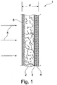
- FIG. 1 shows a sectional view through a filter material according to the invention.
- a filter material 1 according to the invention has a total of at least two layers 2, 4, namely a carrier layer 2 and a fine fiber layer 4. These two layers 2, 4 are connected to one another by a connection region 3. A flow direction through the filter material 1 is shown with arrows 5. On the inflow side of the carrier layer 2 while an impregnation 6 is arranged, which will be discussed in more detail below.
- the filter material 1 has, in the direction of flow 5, a degressive, ie smaller, pore size, with the carrier layer 2 on the inflow side and the fine fiber layer 4 on the outflow side.
- the fine fiber layer 4 may be formed, for example, as a so-called meltblown layer be.
- a total thickness d of the filter material 1 is more than 0.35 mm, in particular more than 0.6 mm. Due to the degressive in the flow direction 5 degressive pore size, the advantages of the individual layers 2, 4 combined with each other and thus a filter material 1 can be achieved with a high absorption capacity and high separation efficiency.
- the support layer 2 alone has a comparatively high absorption capacity (soot absorption capacity) of, for example, 5.0 g / m 2
- the fine fiber layer 4 only has a soot absorption capacity of 0.6 to 0.7 g / m 2 .
- a soot absorption capacity of 6.7 g / m 2 can be achieved, as shown for example in accordance with Table 1.
- the carrier layer 2 may, for example, cellulose with or without art fiber content, wherein a pore diameter between 65 and 85 .mu.m, in particular in the range of about 74 microns, is located.
- the pores of the fine fiber layer 4 however, have a significantly smaller pore diameter between 30 and 40 microns. In each case 40 to 80% of the pores lie in the respective pore diameter ranges.
- the fibers of the fine fiber layer 4 may for example consist of polyamide (PA), polyethylene (PE), polyester or polypropylene (PP).
- the diameter of the fibers of the fine fiber layer 4 is preferably between 1.9 and 3.4 .mu.m, in particular about 2.9 microns.
- the individual layers 2, 3, 4 each themselves. That is, for example, on the upstream side of the carrier layer 2 is a larger pore size than on the downstream side, the is in the region of the connection region 3.
- the pores of the connection region 3 usually have a pore diameter between 30 and 45 microns, wherein the connection region 3 may be formed in particular as an adhesive layer.
- the adhesive may comprise adhesive particles or adhesive fibers which connect the layers 2, 4 with each other.
- the connection area may be formed without material application.
- the connection region can be formed by welding the carrier layer 2 to the fine fiber layer 4.
- the fine fiber layer 4 may also be rolled onto the carrier layer 2.
- the air permeability of the individual layers in the carrier layer 2 is for example 840 l / (m 2 s) and in the fine fiber layer 4 about 645 l / (m 2 s). Due to the connection to the filter material 1 according to the invention whose air permeability is only about 355 l / (m 2 s).
- the filter material 1 By means of the filter material 1 according to the invention a uniform loading of the same over the entire depth can be achieved, in particular, a simultaneous filling of the individual layers and regions 2, 3, 4 can be achieved. In particular, saturation of a single layer or area 2, 3, 4 can thereby be avoided, which would considerably reduce the overall filter performance.
- the pore size profile is harmonized by the connection region 3, which means that a pore size profile is produced, for example, by adhesive fibers or adhesive particle droplets, which effects a gradual progression of the pore size from greater to smaller.
- the pore size is also preferably degressive, that is to say upstream on the basis of a pore size which corresponds to that of the carrier layer 2 and downstream with a pore size which corresponds to that of the fine fiber layer 4.
- the carrier layer 2 is also flame retardant.
- a cellulosic material for such a carrier layer 2, which is flame retardant, usually consists of 25-27 mass% of a resin for strength, rigidity, dimensional stability (especially of embossed spacers / cams) as well as for protection external factors (moisture, moisture, chemicals such as oil, fuel).
- the one-sided impregnation 6 according to the invention applied at least on the inflow side of the carrier layer 2 a smearing of very fine pores (on the downstream side) and a closing or narrowing of fine pores can be reduced by a gusset formation of the resin, so that the pore structure passes through the resin on the clean side, that is, the outflow side of the support layer 2 not at all and on the upstream side, that is only marginally changed on the raw side.
- the resin content in the carrier layer 2 is reduced to 22% by mass, which likewise reduces a smearing of very fine pores, which lie in particular on the outflow side of a cellulose paper (carrier layer 2).
- the filter material 1 according to the invention can be used in particular in air filters of internal combustion engines in automobiles, in particular also for pleated filter elements or for wound inserts with mutually closed channels.
- the arrangement of the individual layers 2, 3, 4 with degressive pore diameter, a total of particularly efficient filter material 1 can be created.
Landscapes
- Chemical & Material Sciences (AREA)
- Chemical Kinetics & Catalysis (AREA)
- Engineering & Computer Science (AREA)
- Combustion & Propulsion (AREA)
- Mechanical Engineering (AREA)
- General Engineering & Computer Science (AREA)
- Filtering Materials (AREA)
Claims (12)
- Matériau filtrant (1), en particulier pour un filtre à air d'un moteur à combustion interne, dans lequel- le matériau filtrant (1) présente dans une direction de circulation (5) une taille de pore dégressive,- le matériau filtrant (1) présente une couche porteuse du côté entrant (2) et une couche de fibres fines du côté sortant (4), en particulier une couche soufflée en fusion, caractérisé en ce que,- entre la couche porteuse (2) et la couche de fibres fines (4) est disposée une zone de liaison (3),- le matériau filtrant (1) présente une épaisseur (d) de d > 0,35 mm,- sur le côté entrant de la couche porteuse (2) est déposée unilatéralement une imprégnation (6),- la couche porteuse (2) est formée d'un matériau de cellulose et l'imprégnation (6) est formée d'une résine,- la teneur en résine dans la couche porteuse (2) est de 22 % en masse.
- Matériau filtrant selon la revendication 1,
caractérisé en ce que,
la couche porteuse (2) présente de la cellulose avec ou sans proportion de fibres synthétiques. - Matériau selon la revendication 1 ou 2,
caractérisé en ce que,
des pores de la couche porteuse (2) présentent un diamètre de pore entre 65 et 85 µm, en particulier d'environ 74 µm. - Matériau filtrant selon l'une des revendications 1 à 3,
caractérisé en ce que,
des pores de la couche de fibres fines (4) présentent un diamètre de pore entre 30 et 40 µm. - Matériau filtrant selon l'une des revendications 1 à 4,
caractérisé en ce que,
la couche de fibres fines (4) présente des fibres de polyamide (PA), de polyéthylène (PE), de polyester ou de polypropylène (PP). - Matériau filtrant selon l'une des revendications 1 à 5,
caractérisé en ce que,
la couche de fibres fines (4) présente des fibres avec un diamètre entre 1,5 et 5 µm, de préférence entre 1,9 et 3,4 µm, en particulier d'environ 2,9 µm. - Matériau filtrant selon l'une des revendications 1 à 6,
caractérisé en ce que,
la couche porteuse (2) et/ou la couche de fibres fines (4) et/ou la zone de liaison (3) présente(nt) dans la direction de circulation (5) une taille de pore dégressive. - Matériau filtrant selon l'une des revendications 1 à 7,
caractérisé en ce que,- des pores de la zone de liaison (3) présentent un diamètre de pore entre 30 et 35 µm, et/ou- la zone de liaison (3) est conçue comme une couche adhésive. - Matériau filtrant selon l'une des revendications 1 à 8,
caractérisé en ce que,- une perméabilité à l'air de la couche porteuse (2) est d'environ 840 l/m2s, et/ou- une perméabilité à l'air de la couche de fibres fines (4) est d'environ 645 l/m2s, et/ou- une perméabilité à l'air du matériau filtrant (1) est d'environ 355 l/M2s. - Matériau filtrant selon l'une des revendications 1 à 9,
caractérisé en ce que- l'imprégnation (6) est conçue comme une imprégnation durcissable formant une réticulation sous l'effet de la chaleur ou- l'imprégnation (6) est conçue comme une imprégnation non durcissable. - Matériau filtrant selon l'une des revendications 1 à 10,
caractérisé en ce que,
l'imprégnation (6) présente des résines phénoliques, des acrylates ou des résines époxy. - Elément filtrant comportant un matériau filtrant (1) selon l'une des revendications 1 à 11, caractérisé en ce que,- l'élément filtrant est conçu comme un filtre en rouleau doté de canaux fermés alternativement, ou- l'élément filtrant est conçu comme un élément filtrant plissé, fermé de façon annulaire ou plat.
Applications Claiming Priority (2)
| Application Number | Priority Date | Filing Date | Title |
|---|---|---|---|
| DE102011086104A DE102011086104A1 (de) | 2011-11-10 | 2011-11-10 | Filtermaterial |
| PCT/EP2012/072081 WO2013068436A1 (fr) | 2011-11-10 | 2012-11-08 | Materiau filtrant |
Publications (2)
| Publication Number | Publication Date |
|---|---|
| EP2776140A1 EP2776140A1 (fr) | 2014-09-17 |
| EP2776140B1 true EP2776140B1 (fr) | 2018-09-12 |
Family
ID=47178666
Family Applications (1)
| Application Number | Title | Priority Date | Filing Date |
|---|---|---|---|
| EP12786945.1A Active EP2776140B1 (fr) | 2011-11-10 | 2012-11-08 | Materiau filtrant et element filtrant |
Country Status (8)
| Country | Link |
|---|---|
| US (1) | US9592465B2 (fr) |
| EP (1) | EP2776140B1 (fr) |
| JP (1) | JP6138812B2 (fr) |
| CN (1) | CN103917283B (fr) |
| BR (1) | BR112014010851A8 (fr) |
| DE (1) | DE102011086104A1 (fr) |
| IN (1) | IN2014KN00927A (fr) |
| WO (1) | WO2013068436A1 (fr) |
Families Citing this family (12)
| Publication number | Priority date | Publication date | Assignee | Title |
|---|---|---|---|---|
| DE102013221340A1 (de) * | 2013-10-21 | 2015-04-23 | Mahle International Gmbh | Filtermaterial, Filterelement und Herstellungsverfahren |
| WO2015028530A2 (fr) * | 2013-08-29 | 2015-03-05 | Mahle International Gmbh | Matériau filtrant, élément filtrant, procédé et dispositif pour produire un matériau filtrant |
| DE102013221341A1 (de) * | 2013-10-21 | 2015-04-23 | Mahle International Gmbh | Filtermaterial, Filterelement und Herstellungsverfahren |
| US9777934B2 (en) * | 2014-02-19 | 2017-10-03 | Fiber Bond Corporation | Panel filter and method for manufacturing the same |
| CA2930592A1 (fr) * | 2015-05-22 | 2016-11-22 | Delta M Incorporated | Filtre a air decomposable et methode de fabrication associee |
| CN104855181A (zh) * | 2015-06-17 | 2015-08-26 | 山东棉花研究中心 | 一种智能恒温棉花育种装置 |
| KR101766115B1 (ko) * | 2016-02-05 | 2017-08-07 | 현대자동차주식회사 | 장수명 자동차용 흡기 필터 및 이의 제조방법 |
| CN107008057A (zh) * | 2017-04-19 | 2017-08-04 | 天津大学 | 一种可清洗的三维复合滤料 |
| CN107998529A (zh) * | 2017-11-27 | 2018-05-08 | 重庆国立元创生物科技有限公司 | 一种微型空气净化器 |
| WO2019246419A1 (fr) * | 2018-06-22 | 2019-12-26 | David Ratchford | Systèmes et procédés pour des véhicules acceptant les fumeurs |
| DE102019100468A1 (de) * | 2019-01-10 | 2020-07-16 | Neenah Gessner Gmbh | Filtermedium für Motorluftfilter |
| CN116726606B9 (zh) * | 2023-07-08 | 2024-08-23 | 江苏金由新材料有限公司 | 一种多孔过滤材料及其制备方法和应用 |
Family Cites Families (41)
| Publication number | Priority date | Publication date | Assignee | Title |
|---|---|---|---|---|
| US3116245A (en) * | 1958-07-23 | 1963-12-31 | Walker Mfg Co | Filter |
| US3096230A (en) * | 1960-06-23 | 1963-07-02 | Southwick W Briggs | Filter medium |
| GB1000038A (fr) * | 1960-12-06 | |||
| GB1522280A (en) * | 1976-06-01 | 1978-08-23 | Hollingsworth & Vose Co | Filter medium and method of making same |
| FR2450791A1 (fr) * | 1979-03-09 | 1980-10-03 | Penarroya Miniere Metall | Nouvel additif au plomb pour les industries du verre et de la ceramique et son procede d'obtention |
| US4470859A (en) * | 1981-06-26 | 1984-09-11 | Diamond Shamrock Chemicals Company | Coated porous substrate formation by solution coating |
| SE434469B (sv) * | 1982-12-13 | 1984-07-30 | Soederhamn Ind Arbetshygien Ab | Stoftavskiljaraggregat |
| JPS61283320A (ja) * | 1985-05-01 | 1986-12-13 | Nippon Denso Co Ltd | 空気清浄器用濾材 |
| US4867662A (en) * | 1987-01-29 | 1989-09-19 | Inax Corporation | Slip casting mold |
| US4723967A (en) * | 1987-04-27 | 1988-02-09 | Advanced Technology Materials, Inc. | Valve block and container for semiconductor source reagent dispensing and/or purification |
| DE3812849C3 (de) * | 1988-04-18 | 1996-03-21 | Gessner & Co Gmbh | Staubfilterbeutel, dessen Herstellung und Verwendung |
| US5084178A (en) * | 1988-06-15 | 1992-01-28 | Pall Corporation | Corrugated filter arrangement with support layer and flow channels |
| JP3014440B2 (ja) * | 1990-11-28 | 2000-02-28 | 三菱製紙株式会社 | 濾材及びその製造法 |
| JPH0713412U (ja) * | 1993-07-30 | 1995-03-07 | 株式会社土屋製作所 | 樹脂含浸濾紙 |
| US5549832A (en) * | 1994-12-22 | 1996-08-27 | Century Manufacturing Company | Vehicle coolant recycling |
| US5472600A (en) | 1995-02-01 | 1995-12-05 | Minnesota Mining And Manufacturing Company | Gradient density filter |
| GB9502292D0 (en) * | 1995-02-06 | 1995-03-29 | Bratton Graham J | Adsorbent material |
| US6103645A (en) * | 1996-04-08 | 2000-08-15 | Shell Oil Company | Foam filter material and process to prepare foam filter material |
| US6139942A (en) * | 1997-02-06 | 2000-10-31 | Cytec Technology, Inc. | Resin composition, a fiber reinforced material having a partially impregnated resin and composites made therefrom |
| DE19731860C1 (de) | 1997-07-24 | 1999-01-28 | Freudenberg Carl Fa | Staubfilterbeutel |
| DE69910660T2 (de) * | 1998-05-11 | 2004-06-17 | Airflo Europe N.V. | Staubfilterbeutel für einen Staubsauger oder Filter, und Verfahren zum Filtern eines Gases |
| US6139595A (en) * | 1998-09-18 | 2000-10-31 | Fleetguard, Inc. | Air/oil coalescer with centrifugally assisted drainage |
| DE29907699U1 (de) | 1999-04-30 | 1999-08-05 | FiberMark Gessner GmbH & Co., 83052 Bruckmühl | Staubfilterbeutel, enthaltend Nanofaservlies |
| US6695148B2 (en) * | 1999-05-27 | 2004-02-24 | Edward C. Homonoff | Transmission filter felt |
| US6746517B2 (en) | 2000-09-05 | 2004-06-08 | Donaldson Company, Inc. | Filter structure with two or more layers of fine fiber having extended useful service life |
| DE10144867A1 (de) * | 2001-09-12 | 2003-03-27 | Mann & Hummel Filter | Filterelement und Verfahren zu seiner Herstellung |
| JP4361263B2 (ja) | 2002-02-07 | 2009-11-11 | 本田技研工業株式会社 | フィルタエレメント |
| DE10221694B4 (de) * | 2002-05-16 | 2018-07-12 | Branofilter Gmbh | Mehrlagiger Filteraufbau, Verwendung eines solchen mehrlagigen Filteraufbaus, Staubfilterbeutel, Taschenfilterbeutel, plissierter Filter, flächiger Abluftfilter und Luftfilter für Kraftfahrzeuge |
| ATE390197T1 (de) * | 2002-05-28 | 2008-04-15 | Hollingsworth & Vose Gmbh | Filtermedium |
| US7008465B2 (en) * | 2003-06-19 | 2006-03-07 | Donaldson Company, Inc. | Cleanable high efficiency filter media structure and applications for use |
| US20090071113A1 (en) * | 2005-06-07 | 2009-03-19 | Toyo Roki Seizo Kabushiki Kaisha | Filter element |
| US9149750B2 (en) * | 2006-09-29 | 2015-10-06 | Mott Corporation | Sinter bonded porous metallic coatings |
| DE102007027268A1 (de) * | 2007-06-11 | 2008-12-18 | Sandler Ag | Filtermedium für die Luft- und Flüssigkeitsfiltration |
| DE202007011447U1 (de) * | 2007-08-16 | 2007-10-11 | Wolf Gmbh & Co. Kg | Filtermedium |
| JP4907582B2 (ja) * | 2008-03-26 | 2012-03-28 | 日本バイリーン株式会社 | エアフィルタ用濾材 |
| DE202009003669U1 (de) | 2009-03-17 | 2010-08-12 | Mann+Hummel Gmbh | Filterelement |
| US8950587B2 (en) * | 2009-04-03 | 2015-02-10 | Hollingsworth & Vose Company | Filter media suitable for hydraulic applications |
| DE102009050447A1 (de) * | 2009-10-23 | 2011-04-28 | Mahle International Gmbh | Filtermaterial |
| US8092768B2 (en) * | 2010-02-11 | 2012-01-10 | Energy & Environmental Research Center Foundation | Advanced particulate matter control apparatus and methods |
| DE102010011512A1 (de) | 2010-03-12 | 2011-09-15 | Mann+Hummel Gmbh | Filtermedium eines Filterelements, Filterelement und Verfahren zur Herstellung eines Filtermediums |
| DE102010014060A1 (de) * | 2010-04-07 | 2011-10-13 | Mahle International Gmbh | Wickelfilterelement und Verwendung |
-
2011
- 2011-11-10 DE DE102011086104A patent/DE102011086104A1/de not_active Withdrawn
-
2012
- 2012-11-08 EP EP12786945.1A patent/EP2776140B1/fr active Active
- 2012-11-08 JP JP2014540446A patent/JP6138812B2/ja not_active Expired - Fee Related
- 2012-11-08 IN IN927KON2014 patent/IN2014KN00927A/en unknown
- 2012-11-08 BR BR112014010851A patent/BR112014010851A8/pt not_active Application Discontinuation
- 2012-11-08 US US14/357,563 patent/US9592465B2/en active Active
- 2012-11-08 WO PCT/EP2012/072081 patent/WO2013068436A1/fr active Application Filing
- 2012-11-08 CN CN201280054359.6A patent/CN103917283B/zh active Active
Non-Patent Citations (1)
| Title |
|---|
| None * |
Also Published As
| Publication number | Publication date |
|---|---|
| IN2014KN00927A (fr) | 2015-10-09 |
| US20150013285A1 (en) | 2015-01-15 |
| CN103917283A (zh) | 2014-07-09 |
| DE102011086104A1 (de) | 2013-05-16 |
| BR112014010851A2 (pt) | 2017-06-13 |
| JP2015504355A (ja) | 2015-02-12 |
| US9592465B2 (en) | 2017-03-14 |
| WO2013068436A1 (fr) | 2013-05-16 |
| EP2776140A1 (fr) | 2014-09-17 |
| BR112014010851A8 (pt) | 2017-06-20 |
| JP6138812B2 (ja) | 2017-05-31 |
| CN103917283B (zh) | 2015-12-09 |
Similar Documents
| Publication | Publication Date | Title |
|---|---|---|
| EP2776140B1 (fr) | Materiau filtrant et element filtrant | |
| DE10221694B4 (de) | Mehrlagiger Filteraufbau, Verwendung eines solchen mehrlagigen Filteraufbaus, Staubfilterbeutel, Taschenfilterbeutel, plissierter Filter, flächiger Abluftfilter und Luftfilter für Kraftfahrzeuge | |
| EP1317949B1 (fr) | Matériau filtrant composite à plusieurs couches pour filtration en série | |
| DE102012010307B4 (de) | Mehrlagiges Filtermaterial zur Flüssigkeitsfiltration sowie daraus hergestelltes Filterelement | |
| EP1790406B1 (fr) | Élément de filtration et procédé de fabrication | |
| EP1791617B1 (fr) | Procede de production d'une couche filtrante et couche filtrante destinee en particulier a un sac filtre a poussiere d'un aspirateur | |
| DE69729936T2 (de) | Hochpräzisionsfilter | |
| EP2911765B1 (fr) | Matériau de filtre à durée d'utilisation accrue et élément filtrant contenant ce matériau de filtre | |
| DE102009050447A1 (de) | Filtermaterial | |
| DE102010011512A1 (de) | Filtermedium eines Filterelements, Filterelement und Verfahren zur Herstellung eines Filtermediums | |
| DE102009006583A1 (de) | Mehrlagiges Filtermaterial für die Flüssigkeitsfiltration | |
| DE102009006586B4 (de) | Filtermedium sowie Filterelement für die Flüssigkeitsfiltration | |
| EP2006008B1 (fr) | Support de filtre pour la filtration d'air et de liquide | |
| EP3393617B1 (fr) | Matériau filtrant et élément filtrant réalisé à partir de celui-ci | |
| EP3049171B1 (fr) | Matériau filtrant et combinaison de matériaux filtrants servant à isoler des liquides et éléments filtrants fabriqués à partir dudit matériau filtrant | |
| DE20207663U1 (de) | Mehrlagiger Filteraufbau | |
| DE102020116689A1 (de) | Melaminharz-Filtervlies | |
| DE102014211021A1 (de) | Imprägnierte Filtermaterialien und daraus hergestellte Filterelemente | |
| EP3721965A1 (fr) | Milieu filtrant pourvu de non-tissé en tant que composite fibreux monocouche et procédé de fabrication d'un tel milieu filtrant | |
| EP2006007B1 (fr) | Filtre à air doté d'une structure multicouche | |
| DE102012010313A1 (de) | Filtermaterial für die Filtration von Prozessflüssigkeiten des Funkenerosionsverfahrens | |
| DE60219293T2 (de) | Faservlies für einen Filter und Filter für einen Motor | |
| EP3078407A1 (fr) | Support de filtre haute performance et sans liant | |
| DE202007008371U1 (de) | Luftfilter mit mehrschichtigem Aufbau |
Legal Events
| Date | Code | Title | Description |
|---|---|---|---|
| PUAI | Public reference made under article 153(3) epc to a published international application that has entered the european phase |
Free format text: ORIGINAL CODE: 0009012 |
|
| 17P | Request for examination filed |
Effective date: 20140422 |
|
| AK | Designated contracting states |
Kind code of ref document: A1 Designated state(s): AL AT BE BG CH CY CZ DE DK EE ES FI FR GB GR HR HU IE IS IT LI LT LU LV MC MK MT NL NO PL PT RO RS SE SI SK SM TR |
|
| DAX | Request for extension of the european patent (deleted) | ||
| GRAP | Despatch of communication of intention to grant a patent |
Free format text: ORIGINAL CODE: EPIDOSNIGR1 |
|
| RIC1 | Information provided on ipc code assigned before grant |
Ipc: F02M 35/08 20060101ALI20180315BHEP Ipc: B01D 39/16 20060101AFI20180315BHEP Ipc: B01D 39/18 20060101ALI20180315BHEP Ipc: B01D 46/52 20060101ALI20180315BHEP |
|
| INTG | Intention to grant announced |
Effective date: 20180328 |
|
| RAX | Requested extension states of the european patent have changed |
Extension state: BA Extension state: ME |
|
| GRAS | Grant fee paid |
Free format text: ORIGINAL CODE: EPIDOSNIGR3 |
|
| GRAA | (expected) grant |
Free format text: ORIGINAL CODE: 0009210 |
|
| DAX | Request for extension of the european patent (deleted) | ||
| AK | Designated contracting states |
Kind code of ref document: B1 Designated state(s): AL AT BE BG CH CY CZ DE DK EE ES FI FR GB GR HR HU IE IS IT LI LT LU LV MC MK MT NL NO PL PT RO RS SE SI SK SM TR |
|
| REG | Reference to a national code |
Ref country code: GB Ref legal event code: FG4D Free format text: NOT ENGLISH |
|
| REG | Reference to a national code |
Ref country code: CH Ref legal event code: EP |
|
| REG | Reference to a national code |
Ref country code: IE Ref legal event code: FG4D Free format text: LANGUAGE OF EP DOCUMENT: GERMAN |
|
| REG | Reference to a national code |
Ref country code: DE Ref legal event code: R096 Ref document number: 502012013441 Country of ref document: DE |
|
| REG | Reference to a national code |
Ref country code: AT Ref legal event code: REF Ref document number: 1039875 Country of ref document: AT Kind code of ref document: T Effective date: 20181015 |
|
| REG | Reference to a national code |
Ref country code: NL Ref legal event code: MP Effective date: 20180912 |
|
| REG | Reference to a national code |
Ref country code: LT Ref legal event code: MG4D |
|
| PG25 | Lapsed in a contracting state [announced via postgrant information from national office to epo] |
Ref country code: NO Free format text: LAPSE BECAUSE OF FAILURE TO SUBMIT A TRANSLATION OF THE DESCRIPTION OR TO PAY THE FEE WITHIN THE PRESCRIBED TIME-LIMIT Effective date: 20181212 Ref country code: GR Free format text: LAPSE BECAUSE OF FAILURE TO SUBMIT A TRANSLATION OF THE DESCRIPTION OR TO PAY THE FEE WITHIN THE PRESCRIBED TIME-LIMIT Effective date: 20181213 Ref country code: FI Free format text: LAPSE BECAUSE OF FAILURE TO SUBMIT A TRANSLATION OF THE DESCRIPTION OR TO PAY THE FEE WITHIN THE PRESCRIBED TIME-LIMIT Effective date: 20180912 Ref country code: RS Free format text: LAPSE BECAUSE OF FAILURE TO SUBMIT A TRANSLATION OF THE DESCRIPTION OR TO PAY THE FEE WITHIN THE PRESCRIBED TIME-LIMIT Effective date: 20180912 Ref country code: SE Free format text: LAPSE BECAUSE OF FAILURE TO SUBMIT A TRANSLATION OF THE DESCRIPTION OR TO PAY THE FEE WITHIN THE PRESCRIBED TIME-LIMIT Effective date: 20180912 Ref country code: BG Free format text: LAPSE BECAUSE OF FAILURE TO SUBMIT A TRANSLATION OF THE DESCRIPTION OR TO PAY THE FEE WITHIN THE PRESCRIBED TIME-LIMIT Effective date: 20181212 Ref country code: LT Free format text: LAPSE BECAUSE OF FAILURE TO SUBMIT A TRANSLATION OF THE DESCRIPTION OR TO PAY THE FEE WITHIN THE PRESCRIBED TIME-LIMIT Effective date: 20180912 |
|
| PG25 | Lapsed in a contracting state [announced via postgrant information from national office to epo] |
Ref country code: AL Free format text: LAPSE BECAUSE OF FAILURE TO SUBMIT A TRANSLATION OF THE DESCRIPTION OR TO PAY THE FEE WITHIN THE PRESCRIBED TIME-LIMIT Effective date: 20180912 Ref country code: LV Free format text: LAPSE BECAUSE OF FAILURE TO SUBMIT A TRANSLATION OF THE DESCRIPTION OR TO PAY THE FEE WITHIN THE PRESCRIBED TIME-LIMIT Effective date: 20180912 Ref country code: HR Free format text: LAPSE BECAUSE OF FAILURE TO SUBMIT A TRANSLATION OF THE DESCRIPTION OR TO PAY THE FEE WITHIN THE PRESCRIBED TIME-LIMIT Effective date: 20180912 |
|
| PGFP | Annual fee paid to national office [announced via postgrant information from national office to epo] |
Ref country code: FR Payment date: 20181129 Year of fee payment: 7 |
|
| PG25 | Lapsed in a contracting state [announced via postgrant information from national office to epo] |
Ref country code: NL Free format text: LAPSE BECAUSE OF FAILURE TO SUBMIT A TRANSLATION OF THE DESCRIPTION OR TO PAY THE FEE WITHIN THE PRESCRIBED TIME-LIMIT Effective date: 20180912 Ref country code: IS Free format text: LAPSE BECAUSE OF FAILURE TO SUBMIT A TRANSLATION OF THE DESCRIPTION OR TO PAY THE FEE WITHIN THE PRESCRIBED TIME-LIMIT Effective date: 20190112 Ref country code: PL Free format text: LAPSE BECAUSE OF FAILURE TO SUBMIT A TRANSLATION OF THE DESCRIPTION OR TO PAY THE FEE WITHIN THE PRESCRIBED TIME-LIMIT Effective date: 20180912 Ref country code: CZ Free format text: LAPSE BECAUSE OF FAILURE TO SUBMIT A TRANSLATION OF THE DESCRIPTION OR TO PAY THE FEE WITHIN THE PRESCRIBED TIME-LIMIT Effective date: 20180912 Ref country code: ES Free format text: LAPSE BECAUSE OF FAILURE TO SUBMIT A TRANSLATION OF THE DESCRIPTION OR TO PAY THE FEE WITHIN THE PRESCRIBED TIME-LIMIT Effective date: 20180912 Ref country code: RO Free format text: LAPSE BECAUSE OF FAILURE TO SUBMIT A TRANSLATION OF THE DESCRIPTION OR TO PAY THE FEE WITHIN THE PRESCRIBED TIME-LIMIT Effective date: 20180912 Ref country code: IT Free format text: LAPSE BECAUSE OF FAILURE TO SUBMIT A TRANSLATION OF THE DESCRIPTION OR TO PAY THE FEE WITHIN THE PRESCRIBED TIME-LIMIT Effective date: 20180912 Ref country code: EE Free format text: LAPSE BECAUSE OF FAILURE TO SUBMIT A TRANSLATION OF THE DESCRIPTION OR TO PAY THE FEE WITHIN THE PRESCRIBED TIME-LIMIT Effective date: 20180912 |
|
| PG25 | Lapsed in a contracting state [announced via postgrant information from national office to epo] |
Ref country code: SM Free format text: LAPSE BECAUSE OF FAILURE TO SUBMIT A TRANSLATION OF THE DESCRIPTION OR TO PAY THE FEE WITHIN THE PRESCRIBED TIME-LIMIT Effective date: 20180912 Ref country code: PT Free format text: LAPSE BECAUSE OF FAILURE TO SUBMIT A TRANSLATION OF THE DESCRIPTION OR TO PAY THE FEE WITHIN THE PRESCRIBED TIME-LIMIT Effective date: 20190112 Ref country code: SK Free format text: LAPSE BECAUSE OF FAILURE TO SUBMIT A TRANSLATION OF THE DESCRIPTION OR TO PAY THE FEE WITHIN THE PRESCRIBED TIME-LIMIT Effective date: 20180912 |
|
| REG | Reference to a national code |
Ref country code: DE Ref legal event code: R097 Ref document number: 502012013441 Country of ref document: DE |
|
| REG | Reference to a national code |
Ref country code: CH Ref legal event code: PL |
|
| PLBE | No opposition filed within time limit |
Free format text: ORIGINAL CODE: 0009261 |
|
| STAA | Information on the status of an ep patent application or granted ep patent |
Free format text: STATUS: NO OPPOSITION FILED WITHIN TIME LIMIT |
|
| PG25 | Lapsed in a contracting state [announced via postgrant information from national office to epo] |
Ref country code: MC Free format text: LAPSE BECAUSE OF FAILURE TO SUBMIT A TRANSLATION OF THE DESCRIPTION OR TO PAY THE FEE WITHIN THE PRESCRIBED TIME-LIMIT Effective date: 20180912 Ref country code: LU Free format text: LAPSE BECAUSE OF NON-PAYMENT OF DUE FEES Effective date: 20181108 Ref country code: DK Free format text: LAPSE BECAUSE OF FAILURE TO SUBMIT A TRANSLATION OF THE DESCRIPTION OR TO PAY THE FEE WITHIN THE PRESCRIBED TIME-LIMIT Effective date: 20180912 |
|
| REG | Reference to a national code |
Ref country code: BE Ref legal event code: MM Effective date: 20181130 |
|
| 26N | No opposition filed |
Effective date: 20190613 |
|
| REG | Reference to a national code |
Ref country code: IE Ref legal event code: MM4A |
|
| GBPC | Gb: european patent ceased through non-payment of renewal fee |
Effective date: 20181212 |
|
| PG25 | Lapsed in a contracting state [announced via postgrant information from national office to epo] |
Ref country code: SI Free format text: LAPSE BECAUSE OF FAILURE TO SUBMIT A TRANSLATION OF THE DESCRIPTION OR TO PAY THE FEE WITHIN THE PRESCRIBED TIME-LIMIT Effective date: 20180912 Ref country code: LI Free format text: LAPSE BECAUSE OF NON-PAYMENT OF DUE FEES Effective date: 20181130 Ref country code: CH Free format text: LAPSE BECAUSE OF NON-PAYMENT OF DUE FEES Effective date: 20181130 |
|
| PG25 | Lapsed in a contracting state [announced via postgrant information from national office to epo] |
Ref country code: IE Free format text: LAPSE BECAUSE OF NON-PAYMENT OF DUE FEES Effective date: 20181108 |
|
| PG25 | Lapsed in a contracting state [announced via postgrant information from national office to epo] |
Ref country code: BE Free format text: LAPSE BECAUSE OF NON-PAYMENT OF DUE FEES Effective date: 20181130 |
|
| PG25 | Lapsed in a contracting state [announced via postgrant information from national office to epo] |
Ref country code: GB Free format text: LAPSE BECAUSE OF NON-PAYMENT OF DUE FEES Effective date: 20181212 |
|
| REG | Reference to a national code |
Ref country code: AT Ref legal event code: MM01 Ref document number: 1039875 Country of ref document: AT Kind code of ref document: T Effective date: 20181108 |
|
| PG25 | Lapsed in a contracting state [announced via postgrant information from national office to epo] |
Ref country code: MT Free format text: LAPSE BECAUSE OF FAILURE TO SUBMIT A TRANSLATION OF THE DESCRIPTION OR TO PAY THE FEE WITHIN THE PRESCRIBED TIME-LIMIT Effective date: 20180912 Ref country code: AT Free format text: LAPSE BECAUSE OF NON-PAYMENT OF DUE FEES Effective date: 20181108 |
|
| PG25 | Lapsed in a contracting state [announced via postgrant information from national office to epo] |
Ref country code: TR Free format text: LAPSE BECAUSE OF FAILURE TO SUBMIT A TRANSLATION OF THE DESCRIPTION OR TO PAY THE FEE WITHIN THE PRESCRIBED TIME-LIMIT Effective date: 20180912 |
|
| PG25 | Lapsed in a contracting state [announced via postgrant information from national office to epo] |
Ref country code: CY Free format text: LAPSE BECAUSE OF FAILURE TO SUBMIT A TRANSLATION OF THE DESCRIPTION OR TO PAY THE FEE WITHIN THE PRESCRIBED TIME-LIMIT Effective date: 20180912 Ref country code: MK Free format text: LAPSE BECAUSE OF NON-PAYMENT OF DUE FEES Effective date: 20180912 Ref country code: HU Free format text: LAPSE BECAUSE OF FAILURE TO SUBMIT A TRANSLATION OF THE DESCRIPTION OR TO PAY THE FEE WITHIN THE PRESCRIBED TIME-LIMIT; INVALID AB INITIO Effective date: 20121108 |
|
| PG25 | Lapsed in a contracting state [announced via postgrant information from national office to epo] |
Ref country code: FR Free format text: LAPSE BECAUSE OF NON-PAYMENT OF DUE FEES Effective date: 20191130 |
|
| PGFP | Annual fee paid to national office [announced via postgrant information from national office to epo] |
Ref country code: DE Payment date: 20231121 Year of fee payment: 12 |
|
| P01 | Opt-out of the competence of the unified patent court (upc) registered |
Effective date: 20240527 |