EP2775299A1 - Vorrichtung zum ermitteln der korrosivität einer kunststoffschmelze - Google Patents
Vorrichtung zum ermitteln der korrosivität einer kunststoffschmelze Download PDFInfo
- Publication number
- EP2775299A1 EP2775299A1 EP20140157700 EP14157700A EP2775299A1 EP 2775299 A1 EP2775299 A1 EP 2775299A1 EP 20140157700 EP20140157700 EP 20140157700 EP 14157700 A EP14157700 A EP 14157700A EP 2775299 A1 EP2775299 A1 EP 2775299A1
- Authority
- EP
- European Patent Office
- Prior art keywords
- electrode
- plastic melt
- cavity
- corrosivity
- housing
- Prior art date
- Legal status (The legal status is an assumption and is not a legal conclusion. Google has not performed a legal analysis and makes no representation as to the accuracy of the status listed.)
- Granted
Links
Images

Classifications
-
- G—PHYSICS
- G01—MEASURING; TESTING
- G01N—INVESTIGATING OR ANALYSING MATERIALS BY DETERMINING THEIR CHEMICAL OR PHYSICAL PROPERTIES
- G01N27/00—Investigating or analysing materials by the use of electric, electrochemical, or magnetic means
- G01N27/02—Investigating or analysing materials by the use of electric, electrochemical, or magnetic means by investigating impedance
- G01N27/04—Investigating or analysing materials by the use of electric, electrochemical, or magnetic means by investigating impedance by investigating resistance
- G01N27/06—Investigating or analysing materials by the use of electric, electrochemical, or magnetic means by investigating impedance by investigating resistance of a liquid
-
- B—PERFORMING OPERATIONS; TRANSPORTING
- B29—WORKING OF PLASTICS; WORKING OF SUBSTANCES IN A PLASTIC STATE IN GENERAL
- B29C—SHAPING OR JOINING OF PLASTICS; SHAPING OF MATERIAL IN A PLASTIC STATE, NOT OTHERWISE PROVIDED FOR; AFTER-TREATMENT OF THE SHAPED PRODUCTS, e.g. REPAIRING
- B29C45/00—Injection moulding, i.e. forcing the required volume of moulding material through a nozzle into a closed mould; Apparatus therefor
- B29C45/17—Component parts, details or accessories; Auxiliary operations
- B29C45/76—Measuring, controlling or regulating
-
- B—PERFORMING OPERATIONS; TRANSPORTING
- B29—WORKING OF PLASTICS; WORKING OF SUBSTANCES IN A PLASTIC STATE IN GENERAL
- B29C—SHAPING OR JOINING OF PLASTICS; SHAPING OF MATERIAL IN A PLASTIC STATE, NOT OTHERWISE PROVIDED FOR; AFTER-TREATMENT OF THE SHAPED PRODUCTS, e.g. REPAIRING
- B29C48/00—Extrusion moulding, i.e. expressing the moulding material through a die or nozzle which imparts the desired form; Apparatus therefor
- B29C48/25—Component parts, details or accessories; Auxiliary operations
- B29C48/92—Measuring, controlling or regulating
-
- G—PHYSICS
- G01—MEASURING; TESTING
- G01N—INVESTIGATING OR ANALYSING MATERIALS BY DETERMINING THEIR CHEMICAL OR PHYSICAL PROPERTIES
- G01N17/00—Investigating resistance of materials to the weather, to corrosion, or to light
- G01N17/02—Electrochemical measuring systems for weathering, corrosion or corrosion-protection measurement
-
- G—PHYSICS
- G01—MEASURING; TESTING
- G01N—INVESTIGATING OR ANALYSING MATERIALS BY DETERMINING THEIR CHEMICAL OR PHYSICAL PROPERTIES
- G01N33/00—Investigating or analysing materials by specific methods not covered by groups G01N1/00 - G01N31/00
- G01N33/44—Resins; Plastics; Rubber; Leather
- G01N33/442—Resins; Plastics
-
- B—PERFORMING OPERATIONS; TRANSPORTING
- B29—WORKING OF PLASTICS; WORKING OF SUBSTANCES IN A PLASTIC STATE IN GENERAL
- B29C—SHAPING OR JOINING OF PLASTICS; SHAPING OF MATERIAL IN A PLASTIC STATE, NOT OTHERWISE PROVIDED FOR; AFTER-TREATMENT OF THE SHAPED PRODUCTS, e.g. REPAIRING
- B29C2945/00—Indexing scheme relating to injection moulding, i.e. forcing the required volume of moulding material through a nozzle into a closed mould
- B29C2945/76—Measuring, controlling or regulating
- B29C2945/76003—Measured parameter
-
- B—PERFORMING OPERATIONS; TRANSPORTING
- B29—WORKING OF PLASTICS; WORKING OF SUBSTANCES IN A PLASTIC STATE IN GENERAL
- B29C—SHAPING OR JOINING OF PLASTICS; SHAPING OF MATERIAL IN A PLASTIC STATE, NOT OTHERWISE PROVIDED FOR; AFTER-TREATMENT OF THE SHAPED PRODUCTS, e.g. REPAIRING
- B29C2945/00—Indexing scheme relating to injection moulding, i.e. forcing the required volume of moulding material through a nozzle into a closed mould
- B29C2945/76—Measuring, controlling or regulating
- B29C2945/76451—Measurement means
- B29C2945/76454—Electrical, e.g. thermocouples
-
- B—PERFORMING OPERATIONS; TRANSPORTING
- B29—WORKING OF PLASTICS; WORKING OF SUBSTANCES IN A PLASTIC STATE IN GENERAL
- B29C—SHAPING OR JOINING OF PLASTICS; SHAPING OF MATERIAL IN A PLASTIC STATE, NOT OTHERWISE PROVIDED FOR; AFTER-TREATMENT OF THE SHAPED PRODUCTS, e.g. REPAIRING
- B29C2948/00—Indexing scheme relating to extrusion moulding
- B29C2948/92—Measuring, controlling or regulating
- B29C2948/92009—Measured parameter
- B29C2948/92238—Electrical properties
-
- B—PERFORMING OPERATIONS; TRANSPORTING
- B29—WORKING OF PLASTICS; WORKING OF SUBSTANCES IN A PLASTIC STATE IN GENERAL
- B29C—SHAPING OR JOINING OF PLASTICS; SHAPING OF MATERIAL IN A PLASTIC STATE, NOT OTHERWISE PROVIDED FOR; AFTER-TREATMENT OF THE SHAPED PRODUCTS, e.g. REPAIRING
- B29C2948/00—Indexing scheme relating to extrusion moulding
- B29C2948/92—Measuring, controlling or regulating
- B29C2948/92323—Location or phase of measurement
- B29C2948/92361—Extrusion unit
- B29C2948/9238—Feeding, melting, plasticising or pumping zones, e.g. the melt itself
-
- B—PERFORMING OPERATIONS; TRANSPORTING
- B29—WORKING OF PLASTICS; WORKING OF SUBSTANCES IN A PLASTIC STATE IN GENERAL
- B29C—SHAPING OR JOINING OF PLASTICS; SHAPING OF MATERIAL IN A PLASTIC STATE, NOT OTHERWISE PROVIDED FOR; AFTER-TREATMENT OF THE SHAPED PRODUCTS, e.g. REPAIRING
- B29C48/00—Extrusion moulding, i.e. expressing the moulding material through a die or nozzle which imparts the desired form; Apparatus therefor
- B29C48/03—Extrusion moulding, i.e. expressing the moulding material through a die or nozzle which imparts the desired form; Apparatus therefor characterised by the shape of the extruded material at extrusion
Definitions
- the present application relates to a device for determining the corrosivity of a plastic melt. It also relates to a machine containing such a device and a method for measuring the corrosivity of plastic melt.
- the corrosivity may be caused by flame-retardant additives, for example.
- flame-retardant additives for example.
- These additives can react, for example, directly with the iron alloys, it is also possible that aggressive chemicals such as inorganic acids arise only in the thermal decomposition of some additives in the production of the plastic melt.
- a device for determining the corrosivity of a plastic melt comprising a housing with a cavity for filling with plastic melt, a first electrode of a first material and a second electrode of a second material, wherein the first and the second electrode each have a contact surface to the Cavity and the first material has a higher standard potential than the second material, and the first and second electrodes are also connectable to each other for determining an electrical current and / or an electrical voltage between the contact surfaces via a measuring element.
- the second electrode Due to the plastic melt in the cavity, the second electrode is attacked at its contact surface by corrosion.
- the described corrosion process can be evaluated metrologically if the two electrodes are connected both electrically conductive via an electrically conductive connection and via the intermediate melt.
- the corrosion process causes electrons to flow from the anode (that is, the electrode from the "less noble" material, ie, the lower standard potential) to the cathode (that is, the electrode that is made of a higher standard potential material). So it flows at the end of this corrosion process, a current whose strength via a measuring element for determining the electrical Current is determined. This in turn is a measure of the corrosiveness.
- the absolute value of the current gives information about the expected corrosion rates or corrosion rates, which depend on many influencing factors and are difficult to estimate without such a measurement.
- statements on corrosiveness can be obtained from the measurement of other electrical quantities, e.g. of the potential between the electrodes.
- a development of the device for measuring the corrosivity provides for the installation of additional sensors, preferably temperature sensors, pressure sensors, sensors for optical spectroscopy, ultrasonic measurement, dielectric spectroscopy and / or light scattering. In this way, all relevant parameters for the measurement can be normalized.
- the device for measuring the corrosivity has an opening for supplying plastic melt, for example for connecting a screw extruder.
- the device according to the invention can be attached directly to any devices for the production of plastic melt to make standardized measurements here.
- the hollow space which can be filled with plastic melt is stretched longitudinally and, at least in regions, has a rectangular, round or oval cross-section or combinations thereof at right angles to its longitudinal direction.
- the advantage here is that these geometric basic forms allow the introduction of electrodes with the largest possible contact surfaces that are flush with the interior of the cavity. In addition, with standard geometries also the cleaning of the cavity will be easier.
- the one or both electrodes protrude into the cavity, so that the melt is sheared over the electrode surfaces.
- the resulting mechanical wear allows simultaneous conclusions about the abrasiveness of the melt.
- the first material is copper, platinum, palladium, amorphous carbon, rhodium, iridium, nickel, silver, gold, iron or alloys of the abovementioned and / or the second material is zinc or an iron alloy, in particular carbon steel.
- the first and / or the second electrode are embedded as parts of an insert in the housing.
- the advantage of this is that, for example, for cleaning purposes or wear (especially the second electrode, ie the electrode with the lower standard potential) replacement of the electrode is easily possible.
- the insert can also be designed as a screw insert. As a result, the attachment of the insert withstands even the highest pressures and is still tight.
- the electrode "readjusted".
- the electrode is electrically isolated from the housing by electrical insulation (eg, a ceramic sleeve).
- An alternative is to combine both electrodes (i.e., the first and second electrodes) in a single insert (electrically isolated from each other).
- the housing is separable (for example, is divided into two) for opening the cavity and for better accessibility to the contact surfaces.
- the contact surface can be easily and thoroughly cleaned, in addition, a visual inspection of the surface is quite possible, for example, to draw conclusions about the abrasiveness.
- a further development provides that a plurality of pairs of first and second electrodes are provided. This makes it possible for different measurements to be made at the same time. For example, it is possible to provide different materials for the second electrodes so as to obtain as many measurements as possible for a very specific plastic melt using as little plastic material as possible.
- Another aspect of the invention is a machine comprising a device for producing plastic melt and a device for determining the corrosivity, as described above.
- the machines may be, for example, an injection molding machine, an extruder or a kneader.
- the machine has two outputs for plastic melt, wherein a first output is connected to the opening of the device for determining the corrosivity and the second output of the machine is not connected to the device for determining the corrosivity.
- the second output e.g. an injection mold is connected and here continuously certain products are produced.
- the additional first output makes it possible to measure the corrosivity of the respective material during operation.
- first output can be closed separately from the second output.
- a measurement can be carried out "at the touch of a button", but otherwise the machine can be operated completely normally.
- the invention relates to a method for measuring the corrosivity of plastic melt, wherein plastic melt is introduced into a cavity and a first electrode of a first material and a second electrode of a second material are provided and the first and the second electrode each have a contact surface for Have cavity out, wherein the first material has a higher standard potential than the second material and the first and the second electrode are also connected to one another via a measuring element and an electrical current and / or an electrical voltage between the first and second electrode is determined.
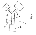
- Fig. 1 shows (by way of example) an injection molding machine. This first comprises a device for the production of plastic melt 10, which contains a hopper for filling plastic granulate 10a, a heater, not shown, and a drive 10b. At the end, a first exit 11a and a second exit 11b are attached.
- the second exit 11b can be connected to a plastic injection mold 12 in which, for example, plastic trays, etc. can be produced.
- the first exit 11a is connected to an opening 6 of a device 1 for determining the corrosivity of a plastic melt.
- the outlet 11a is closable, so that when the outlet is closed, only the outlet 11b remains open and a flow of plastic melt to the device 1 is prevented.
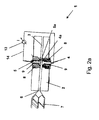
- Fig. 2a shows a screw extruder 7, to an opening 6 for supplying plastic melt into the device 1 for determining the corrosivity connected.
- the device has a housing 2 with a cavity 3 which can be filled with plastic melt.
- the cavity may have a rectangular, round or even oval cross-section in the longitudinal direction.
- the first electrode 4 is made of a first material and the second electrode 5 of a second material, wherein the first material has a higher standard potential than the second material.
- the first electrode has a contact surface 4a to the cavity
- the second electrode has a contact surface 5a to the cavity
- the electrodes are surrounded by an electrical insulation 9 in the form of a ceramic sleeve, which is also part of an insert 8, which can be screwed into the housing 2 is.
- the electrodes are also electrically connected to each other at their ends remote from the cavity via an electrical line 14 and a measuring element 13 for measuring electric current.
- the contact surface 4a and the contact surface 5a are mounted substantially flush in the wall of the cavity 3 of the housing 2 of the device 1. It makes sense that the first material for the first electrode 4, for example, copper, platinum, palladium or alloys of the aforementioned metals are used and for the second material, ie the second electrode 5, for example carbon steel.
- the first material for the first electrode 4 for example, copper, platinum, palladium or alloys of the aforementioned metals are used and for the second material, ie the second electrode 5, for example carbon steel.
- the first material for the first electrode 4 for example, copper, platinum, palladium or alloys of the aforementioned metals are used and for the second material, ie the second electrode 5, for example carbon steel.
- the first material for the first electrode 4 for example, copper, platinum, palladium or alloys of the aforementioned metals are used and for the second material, ie the second electrode 5, for example carbon steel.
- the second material ie the second electrode 5 for example carbon steel.
- the device shown
- Fig. 2b shows the unfolded state of an alternative device 1.
- the structure with respect to the electrodes etc. is identical in this case, good to see is perpendicular to the longitudinal direction of the cavity 3 rectangular cross-sectional shape of the cavity.
- Noteworthy is the place of supply of the plastic melt (see opening 6), which is different than in Fig. 2a is.
- the housing 2 is the cavity 3 exposable, so that the contact surfaces 4a and 5a are particularly easy to clean (along with the other walls of the cavity), also can also be easily carried out a visual inspection of the cleaned contact surfaces of the electrodes.
- FIGS. 1 to 2b Objects shown are suitable for carrying out a method for measuring the corrosivity of plastic melt, wherein plastic melt is introduced into a cavity (3) and a first electrode (4) made of a first material and a second electrode (5) are provided from a second material, and the first and the second electrode each have a contact surface to the cavity, wherein the first material has a higher standard potential than the second material and the first (4) and the second electrode (5) are also connectable to each other via a measuring element and by means of the measuring element an electrical current and / or an electrical voltage between the first (4) and second (5) electrode is determined.
Landscapes
- Life Sciences & Earth Sciences (AREA)
- Chemical & Material Sciences (AREA)
- Health & Medical Sciences (AREA)
- Engineering & Computer Science (AREA)
- General Health & Medical Sciences (AREA)
- Pathology (AREA)
- Immunology (AREA)
- General Physics & Mathematics (AREA)
- Physics & Mathematics (AREA)
- Analytical Chemistry (AREA)
- Biochemistry (AREA)
- Mechanical Engineering (AREA)
- Environmental Sciences (AREA)
- Environmental & Geological Engineering (AREA)
- Ecology (AREA)
- Biodiversity & Conservation Biology (AREA)
- Food Science & Technology (AREA)
- Medicinal Chemistry (AREA)
- Manufacturing & Machinery (AREA)
- Chemical Kinetics & Catalysis (AREA)
- Electrochemistry (AREA)
- Extrusion Moulding Of Plastics Or The Like (AREA)
- Injection Moulding Of Plastics Or The Like (AREA)
- Investigating Or Analyzing Materials By The Use Of Electric Means (AREA)
Abstract
Description
- Die vorliegende Anmeldung betrifft eine Vorrichtung zum Ermitteln der Korrosivität einer Kunststoffschmelze. Es betrifft außerdem eine Maschine, enthaltend eine solche Vorrichtung sowie ein Verfahren zum Messen der Korrosivität von Kunststoffschmelze.
- Je nach Zusammensetzung weisen manche Polymerkunststoffe hochgradig korrosive Eigenschaften gegenüber Eisenlegierungen auf. Diese korrosiven Eigenschaften (Korrosivität) wirken sich negativ beispielsweise auf Teile von Kunststoffverarbeitungsmaschinen aus.
- Die Korrosivität kann hierbei beispielsweise durch flammhemmende Additive bedingt sein. Diese Additive können beispielsweise unmittelbar mit den Eisenlegierungen reagieren, möglich ist es auch, dass aggressive Chemikalien wie anorganische Säuren erst bei der thermischen Zersetzung mancher Additive bei der Herstellung der Kunststoffschmelze entstehen.
- Um ein Kunststoffmaterial zu entwickeln, das einerseits in Bezug z.B. auf Flammschutz höchsten Anforderungen genügt und außerdem beispielsweise Kunststoffverarbeitungsmaschinen nicht zu stark angreift, muss hier ein entsprechendes Optimum mittels einer geeigneten Messmethode gefunden werden. Die Methode sollte einerseits reproduzierbare Ergebnisse liefern, andererseits sollte die für die Messung benötigte Materialmenge möglichst klein sein.
- Es ist daher die Aufgabe der vorliegenden Erfindung, entsprechende Vorrichtungen bzw. Maschinen bzw. Verfahren zur Verfügung zu stellen, die auf eine kostengünstige und einfache Weise die Korrosivität unterschiedlicher Kunststoffschmelzen ermitteln.
- Diese Aufgabe wird durch die Gegenstände der unabhängigen Patentansprüche gelöst. Dies ist zunächst eine Vorrichtung zum Ermitteln der Korrosivität einer Kunststoffschmelze, enthaltend ein Gehäuse mit einem Hohlraum zur Füllung mit Kunststoffschmelze, eine erste Elektrode aus einem ersten Material und eine zweite Elektrode aus einem zweiten Material, wobei die erste und die zweite Elektrode jeweils eine Kontaktoberfläche zum Hohlraum hin aufweisen und das erste Material ein höheres Standardpotential als das zweite Material aufweist, und die erste und zweite Elektrode außerdem zur Bestimmung eines elektrischen Stroms und/oder einer elektrischen Spannung zwischen den Kontaktoberflächen über ein Messelement miteinander verbindbar sind.
- Durch die im Hohlraum befindliche Kunststoffschmelze wird die zweite Elektrode an ihrer Kontaktoberfläche durch Korrosion angegriffen. Der beschriebene Korrosionsvorgang ist messtechnisch auswertbar, wenn die beiden Elektroden sowohl elektrisch leitend über eine elektrisch leitende Verbindung als auch über die dazwischen liegende Schmelze verbunden sind. Der Korrosionsprozess hat zur Folge, dass Elektronen von der Anode (also der Elektrode aus dem "unedleren" Material, d.h. mit dem niedrigeren Standardpotential) zur Kathode (also der Elektrode, das aus einem Material mit einem höheren Standardpotential ist) fließen. Es fließt also bei Ablauf dieses Korrosionsprozesses ein Strom, dessen Stärke über ein Messelement zur Bestimmung des elektrischen Stroms ermittelbar ist. Dies ist wiederum ein Maß für die Korrosivität.
- Der Absolutwert des Stroms gibt unter Berücksichtigung der Größe der Kontaktflächen der Elektroden Auskunft über die zu erwartenden Korrosionsraten bzw. Korrosionsgeschwindigkeiten, die von vielen Einflussgrößen abhängen und ohne eine solche Messung nur schwer abschätzbar sind. Alternativ lassen sich auch Aussagen zur Korrosivität aus der Messung anderer elektrischer Größen, z.B. des Potentials zwischen den Elektroden erhalten.
- Eine Weiterbildung der Vorrichtung zur Messung der Korrosivität sieht die Installation von zusätzlichen Sensoren vor, vorzugsweise Temperatursensoren, Drucksensoren, Sensoren für optische Spektroskopie, Ultraschallmesstechnik, dielektrische Spektroskopie und/oder Lichtstreuung. Auf diese Weise können sämtliche für die Messung relevanten Parameter normiert werden.
- Eine Weiterbildung sieht vor, dass die Vorrichtung zur Messung der Korrosivität eine Öffnung zur Zuführung von Kunststoffschmelze aufweist, beispielsweise zum Anschluss eines Schneckenextruders. Somit kann die erfindungsgemäße Vorrichtung unmittelbar an beliebige Vorrichtungen zur Herstellung von Kunststoffschmelze angegliedert werden, um hier normierte Messungen vorzunehmen.
- Eine weitere Weiterbildung sieht vor, dass der mit Kunststoffschmelze befüllbare Hohlraum längsgestreckt ist und senkrecht zu seiner Längsrichtung zumindest bereichsweise einen rechteckigen, runden oder ovalen Querschnitt oder Kombinationen davon aufweist. Der Vorteil ist hierbei, dass diese geometrischen Grundformen die Einbringung von Elektroden mit möglichst großen Kontaktoberflächen, die zum Innenraum des Hohlraums bündig sind, ermöglichen. Außerdem wird bei Standardgeometrien auch die Reinigung des Hohlraums leichter möglich sein.
- In einer Weiterbildung ragt die eine oder beide Elektroden in den Hohlraum hinein, so dass die Schmelze über die Elektrodenflächen geschert wird. Der dabei stattfindende mechanische Verschleiß lässt gleichzeitige Rückschlüsse auf die Abrasivität der Schmelze zu.
- Eine Weiterbildung sieht vor, dass das erste Material Kupfer, Platin, Palladium, amorpher Kohlenstoff, Rhodium, Iridium, Nickel, Silber, Gold, Eisen oder Legierungen der Vorgenannten ist und/oder das zweite Material Zink oder eine Eisenlegierung, insbesondere Kohlenstoffstahl, ist.
- Eine Weiterbildung sieht vor, dass die erste und/oder die zweite Elektrode als Teile eines Einsatzes in das Gehäuse eingelassen sind. Der Vorteil hiervon ist, dass beispielsweise zu Reinigungszwecken oder bei Abnutzung (insbesondere der zweiten Elektrode, also der Elektrode mit dem niedrigeren Standardpotential) ein Auswechseln der Elektrode einfach möglich ist. Beispielsweise kann der Einsatz auch als Schraubeinsatz ausgeführt sein. Hierdurch hält die Befestigung des Einsatzes auch höchsten Drücken stand und ist trotzdem dicht. Außerdem kann auf diese Weise gegebenenfalls die Elektrode "nachjustiert" werden. Vorzugsweise ist die Elektrode elektrisch gegenüber dem Gehäuse durch eine elektrische Isolierung (beispielsweise eine Keramikhülse) isoliert.
- Prinzipiell ist es auch möglich, lediglich eine Elektrode als externen Einsatz vorzusehen und bei einem geeigneten Material des Gehäuses (welches beispielsweise selbst aus Kohlenstoffstoffstahl ist) einen definierten Teil des Gehäuses als "andere Elektrode" zu nutzen.
- Eine Alternative sieht vor, dass beide Elektroden (d.h. die erste und zweite Elektrode) in einem einzigen Einsatz (elektrisch gegeneinander isoliert) kombiniert sind.
- Eine Weiterbildung sieht vor, dass das Gehäuse trennbar ist (beispielsweise zweigeteilt ist) zum Öffnen des Hohlraums und zur besseren Zugänglichkeit zu den Kontaktoberflächen. Hierdurch kann zum einen die Kontaktoberfläche leicht und gründlich gereinigt werden, außerdem ist eine Sichtkontrolle der Oberfläche gut möglich, um beispielsweise Rückschlüsse auf die Abrasivität zu ziehen.
- Eine weitere Weiterbildung sieht vor, dass mehrere Paare von ersten und zweiten Elektroden vorgesehen sind. Hierdurch wird es möglich, dass verschiedene Messungen zur gleichen Zeit durchgeführt werden. Beispielsweise ist es möglich, verschiedene Materialien für die zweiten Elektroden vorzusehen, um so für eine ganz bestimmte Kunststoffschmelze unter Verwendung von möglichst wenig Kunststoffmaterial möglichst viele Messwerte zu erhalten.
- Ein weiterer Aspekt der Erfindung ist eine Maschine, enthaltend eine Vorrichtung zur Erzeugung von Kunststoffschmelze sowie eine Vorrichtung zum Ermitteln der Korrosivität, wie sie oben beschrieben ist. Bei den Maschinen kann es sich beispielsweise um eine Spritzgussmaschine, einen Extruder oder einen Kneter handeln. Hierbei sieht eine vorteilhafte Weiterbildung vor, dass die Maschine zwei Ausgänge für Kunststoffschmelze aufweist, wobei ein erster Ausgang mit der Öffnung der Vorrichtung zum Ermitteln der Korrosivität verbunden ist und der zweite Ausgang der Maschine nicht mit der Vorrichtung zur Ermittlung der Korrosivität verbunden ist. Hierdurch wird es beispielsweise möglich, dass an den zweiten Ausgang, z.B. eine Spritzgussform angeschlossen wird und hier kontinuierlich bestimmte Produkte hergestellt werden. Durch den zusätzlichen ersten Ausgang wird es möglich, im laufenden Betrieb die Korrosivität des jeweiligen Materials zu messen.
- Eine vorteilhafte Weiterbildung sieht vor, dass der erste Ausgang getrennt vom zweiten Ausgang verschließbar ist. Somit kann "auf Knopfdruck" eine Messung durchgeführt werden, ansonsten kann die Maschine aber völlig normal betrieben werden.
- Die Erfindung betrifft schließlich noch ein Verfahren zum Messen der Korrosivität von Kunststoffschmelze, wobei Kunststoffschmelze in einen Hohlraum eingebracht wird und eine erste Elektrode aus einem ersten Material sowie eine zweite Elektrode aus einem zweiten Material vorgesehen sind und die erste und die zweite Elektrode jeweils eine Kontaktoberfläche zum Hohlraum hin aufweisen, wobei das erste Material ein höheres Standardpotential als das zweite Material aufweist und die erste und die zweite Elektrode außerdem über ein Messelement miteinander verbindbar sind und ein elektrischer Strom und/oder eine elektrische Spannung zwischen erster und zweiter Elektrode ermittelt wird.
- Vorzugsweise wird bei Einsatz des Verfahrens weniger als 1000 g Kunststoffschmelze benötigt.
- Die Erfindung wird nun anhand mehrerer Figuren erläutert. Es zeigen:
- Fig. 1
- eine erfindungsgemäße Maschine mit zwei Ausgängen, wobei der erste Ausgang mit einer Vorrichtung zum Ermitteln der Korrosivität verbunden ist.
- Fig. 2a
- einen Querschnitt durch eine erfindungsgemäße Vorrichtung zur Messung der Korrosivität mit einem daran angeschlossenen Schneckenextruder und
- Fig. 2b
- die Darstellung einer alternativen Bauform einer erfindungsgemäßen Vorrichtung zum Ermitteln der Korrosivität, wobei hier das Gehäuse im geöffneten Zustand gezeigt ist.
-
Fig. 1 zeigt (beispielhaft) eine Spritzgussmaschine. Diese weist zunächst eine Vorrichtung zur Erzeugung von Kunststoffschmelze 10 auf, die einen Einfülltrichter zum Einfüllen von Kunststoffgranulat 10a enthält, eine nicht dargestellte Heizeinrichtung sowie einen Antrieb 10b. Am Ende sind ein erster Ausgang 11a und ein zweiter Ausgang 11b angebracht. - Der zweite Ausgang 11b ist mit einer Kunststoffspritzgussform 12 verbindbar, in der beispielsweise Kunststoffwannen etc. herstellbar sind. Der erste Ausgang 11a ist mit einer Öffnung 6 einer Vorrichtung 1 zum Ermitteln der Korrosivität einer Kunststoffschmelze verbunden.
- Der Ausgang 11a ist verschließbar, so dass bei einem Verschluss dieses Ausgangs lediglich der Ausgang 11b offen bleibt und ein Fluss von Kunststoffschmelze zu der Vorrichtung 1 unterbunden wird.
- Im Folgenden wird anhand der
Fign. 2a und2b auf Details der Vorrichtung zum Ermitteln der Korrosivität einer Kunststoffschmelze eingegangen. -
Fig. 2a zeigt einen Schneckenextruder 7, der an eine Öffnung 6 zur Zuführung von Kunststoffschmelze in die Vorrichtung 1 zur Ermittlung der Korrosivität angeschlossen ist. Die Vorrichtung weist ein Gehäuse 2 auf mit einem mit Kunststoffschmelze befüllbaren Hohlraum 3. - Der Hohlraum kann in Längsrichtung einen rechteckigen, runden oder auch ovalen Querschnitt aufweisen.
- Gezeigt sind außerdem zwei Elektroden, eine erste Elektrode 4 sowie eine zweite Elektrode 5. Die erste Elektrode 4 ist aus einem ersten Material und die zweite Elektrode 5 aus einem zweiten Material, wobei das erste Material ein höheres Standardpotential als das zweite Material aufweist.
- Die erste Elektrode hat eine Kontaktoberfläche 4a zum Hohlraum hin, die zweite Elektrode hat eine Kontaktoberfläche 5a zum Hohlraum hin, Die Elektroden sind von einer elektrischen Isolierung 9 in Form einer Keramikhülse umgeben, die ebenfalls Teil eines Einsatzes 8 ist, der in das Gehäuse 2 einschraubbar ist. Die Elektroden sind außerdem an ihren dem Hohlraum abgewandten Enden elektrisch miteinander über eine elektrische Leitung 14 und ein Messelement 13 zur Messung von elektrischem Strom verbunden.
- Die Kontaktoberfläche 4a bzw. die Kontaktoberfläche 5a sind im Wesentlichen bündig in der Wandung des Hohlraums 3 des Gehäuses 2 der Vorrichtung 1 angebracht. Hierbei bietet es sich an, dass als erstes Material für die erste Elektrode 4 beispielsweise Kupfer, Platin, Palladium oder Legierungen der vorgenannten Metalle verwendet werden und für das zweite Material, also die zweite Elektrode 5, beispielsweise Kohlenstoffstahl. Die in
Fig. 2a gezeigte Vorrichtung weist lediglich ein Elektrodenpaar auf. Es ist jedoch auch möglich, entlang der Länge des Hohlraums 3 mehrere Elektrodenpaare einander gegenüberliegend anzuordnen, um so mehrere Messungen (beispielsweise mit unterschiedlichen Elektrodenmaterialien) auf einmal durchführen zu können. -
Fig. 2b zeigt den aufgeklappten Zustand einer alternativen Vorrichtung 1. Der Aufbau bezüglich der Elektroden etc. ist hierbei identisch, gut zu sehen ist die senkrecht zur Längsrichtung des Hohlraums 3 rechteckige Querschnittsform des Hohlraums. Bemerkenswert ist der Ort der Zuführung der Kunststoffschmelze (siehe Öffnung 6), der anders als inFig. 2a ist. Die inFig. 2b gezeigte Vorrichtung ist zweigeteilt, durch ein Aufklappen des Gehäuses 2 ist der Hohlraum 3 freilegbar, so dass die Kontaktflächen 4a und 5a besonders leicht gereinigt werden können (zusammen mit den übrigen Wänden des Hohlraums), außerdem kann auch leicht eine Sichtprüfung der gereinigten Kontaktoberflächen der Elektroden erfolgen. - Die in den
Fign. 1 bis 2b gezeigten Gegenstände eignen sich zur Durchführung eines Verfahrens zum Messen der Korrosivität von Kunststoffschmelze, wobei Kunststoffschmelze in einen Hohlraum (3) eingebracht wird und eine erste Elektrode (4) aus einem ersten Material sowie eine zweite Elektrode (5) aus einem zweiten Material vorgesehen sind und die erste und die zweite Elektrode jeweils eine Kontaktoberfläche zum Hohlraum hin aufweisen, wobei das erste Material ein höheres Standardpotential als das zweite Material aufweist und die erste (4) und die zweite Elektrode (5) außerdem über ein Messelement miteinander verbindbar sind und mittels des Messelements ein elektrischer Strom und/oder eine elektrische Spannung zwischen erster (4) und zweiter (5) Elektrode ermittelt wird. -
- 1
- Vorrichtung zum Ermitteln der Korrosivität
- 2
- Gehäuse
- 3
- Hohlraum
- 4
- erste Elektrode
- 4a
- Kontaktoberfläche der ersten Elektrode
- 5
- zweite Elektrode
- 5a
- Kontaktoberfläche der zweiten Elektrode
- 6
- Öffnung zur Zuführung von Kunststoffschmelze
- 7
- Schneckenextruder
- 8
- Einsatz
- 9
- Isolierung
- 10
- Vorrichtung zur Erzeugung von Kunststoffschmelze
- 10a
- Einfülltrichter
- 10b
- Antrieb
- 11a
- erster Ausgang
- 11b
- zweiter Ausgang
- 12
- Kunststoffspritzgussform
- 13
- Messelement
- 14
- elektrische Leitung
Claims (12)
- Vorrichtung (1) zum Ermitteln der Korrosivität einer Kunststoffschmelze, enthaltend• ein Gehäuse (2) mit einem Hohlraum (3) zur Füllung mit Kunststoffschmelze,• eine erste Elektrode (4) aus einem ersten Material und eine zweite Elektrode (5) aus einem zweiten Material, wobei die erste und die zweite Elektrode jeweils eine Kontaktoberfläche (4a, 5a) zum Hohlraum hin aufweisen, wobei• das erste Material ein höheres Standardpotential als das zweite Material aufweist, und• die erste (4) und zweite Elektrode (5) außerdem zur Bestimmung eines elektrischen Stroms und/oder einer elektrischen Spannung zwischen den Kontaktoberflächen (4a, 5a) über ein Messelement miteinander verbindbar sind.
- Vorrichtung nach Anspruch 1, dadurch gekennzeichnet, dass diese eine Öffnung (6) zur Zuführung von Kunststoffschmelze aufweist, vorzugsweise zum Anschluss eines Schneckenextruders.
- Vorrichtung nach einem der vorhergehenden Ansprüche, dadurch gekennzeichnet, dass der Hohlraum (3) zumindest bereichsweise längsgestreckt ist und senkrecht zur Längsrichtung des Hohlraums (3) und vorzugsweise einen rechteckigen, runden oder ovalen Querschnitt oder Kombinationen davon aufweist.
- Vorrichtung nach einem der vorhergehenden Ansprüche, dadurch gekennzeichnet, dass das erste Material Kupfer, Platin, Palladium, amorpher Kohlenstoff, Rhodium, Iridium, Nickel, Silber, Gold, Eisen oder Legierungen der Vorgenannten ist und/oder das zweite Material Zink oder eine Eisenlegierung, insbesondere Kohlenstoffstahl, ist.
- Vorrichtung nach einem der vorhergehenden Ansprüche, dadurch gekennzeichnet, dass die erste und/oder die zweite Elektrode (4, 5) als Teile eines Einsatzes (8) in das Gehäuse eingelassen sind.
- Vorrichtung nach Anspruch 5, dadurch gekennzeichnet, dass der Einsatz eine elektrische Isolierung (9) der Elektrode gegenüber dem Gehäuse aufweist.
- Vorrichtung nach einem der vorhergehenden Ansprüche, dadurch gekennzeichnet, dass das Gehäuse (2) trennbar ist zum Öffnen des Hohlraums (3) und zur besseren Zugänglichkeit zu den Kontaktoberflächen (4a, 5a).
- Vorrichtung nach einem der vorhergehenden Ansprüche, dadurch gekennzeichnet, dass mehrere Paare von ersten und zweiten Elektroden (4, 5) vorgesehen sind.
- Maschine, enthaltend eine Vorrichtung zur Erzeugung von Kunststoffschmelze sowie eine Vorrichtung nach einem der vorhergehenden Ansprüche.
- Maschine nach Anspruch 9, enthaltend zwei Ausgänge für Kunststoffschmelze, wobei ein erster Ausgang (11a) mit der Öffnung (6) der Vorrichtung zum Ermitteln der Korrosivität verbunden ist und der zweite Ausgang (11b) nicht mit der Vorrichtung zur Ermittlung der Korrosionsstärke verbunden ist.
- Maschine nach Anspruch 10, dadurch gekennzeichnet, dass der erste Ausgang (11a) getrennt vom zweiten Ausgang (11b) verschließbar ist.
- Verfahren zum Messen der Korrosivität von Kunststoffschmelze, wobei Kunststoffschmelze in einen Hohlraum (3) eingebracht wird und eine erste Elektrode (4) aus einem ersten Material sowie eine zweite Elektrode (5) aus einem zweiten Material vorgesehen sind und die erste und die zweite Elektrode jeweils eine Kontaktoberfläche zum Hohlraum hin aufweisen, wobei das erste Material ein höheres Standardpotential als das zweite Material aufweist und die erste (4) und die zweite Elektrode (5) außerdem über ein Messelement miteinander verbindbar sind und ein elektrischer Strom und/oder eine elektrische Spannung zwischen erster (4) und zweiter (5) Elektrode ermittelt wird.
Applications Claiming Priority (1)
| Application Number | Priority Date | Filing Date | Title |
|---|---|---|---|
| DE102013203747.3A DE102013203747A1 (de) | 2013-03-05 | 2013-03-05 | Vorrichtung zum ermitteln der korrosivität einer kunststoffschmelze |
Publications (2)
| Publication Number | Publication Date |
|---|---|
| EP2775299A1 true EP2775299A1 (de) | 2014-09-10 |
| EP2775299B1 EP2775299B1 (de) | 2016-05-11 |
Family
ID=50230930
Family Applications (1)
| Application Number | Title | Priority Date | Filing Date |
|---|---|---|---|
| EP14157700.7A Not-in-force EP2775299B1 (de) | 2013-03-05 | 2014-03-04 | Maschine mit einer Vorrichtung zur Erzeugung von Kunststoffschmelze und einer Vorrichtung zum Ermitteln der Korrosivität dieser Kunststoffschmelze, sowie Verfahren zur Korrosivitätsermittlung mittels dieser Maschine |
Country Status (4)
| Country | Link |
|---|---|
| US (1) | US9568446B2 (de) |
| EP (1) | EP2775299B1 (de) |
| DE (1) | DE102013203747A1 (de) |
| ES (1) | ES2586143T3 (de) |
Cited By (1)
| Publication number | Priority date | Publication date | Assignee | Title |
|---|---|---|---|---|
| EP3053726A1 (de) * | 2015-02-07 | 2016-08-10 | HÄNDLE GmbH Maschinen und Anlagenbau | Vorrichtung zur Verschleißcharakterisierung und Extruderanordnung |
Citations (3)
| Publication number | Priority date | Publication date | Assignee | Title |
|---|---|---|---|---|
| US3259840A (en) * | 1962-05-04 | 1966-07-05 | Union Oil Co | Apparatus and method for determining soil corrositivity |
| US8111078B1 (en) * | 2008-08-18 | 2012-02-07 | Xiaodong Sun Yang | Oxidizing power sensor for corrosion monitoring |
| EP2551659A2 (de) * | 2011-07-27 | 2013-01-30 | Goettfert Werkstoff-Pruefmaschinen Gmbh | Vorrichtung und Verfahren zur Prüfung der Reinheit und der rheologischen Eigenschaften von Kunststoffschmelzen |
Family Cites Families (22)
| Publication number | Priority date | Publication date | Assignee | Title |
|---|---|---|---|---|
| US2448676A (en) * | 1943-04-23 | 1948-09-07 | Hpm Dev Corp | Method of injection molding |
| US3486996A (en) * | 1966-06-16 | 1969-12-30 | Petrolite Corp | Corrosion test probe |
| US3491012A (en) * | 1968-07-22 | 1970-01-20 | Petrolite Corp | Corrosion test probe assembly |
| US3728058A (en) * | 1971-11-01 | 1973-04-17 | Gen Electric | Plastic melt temperature control |
| IT1134167B (it) * | 1980-11-04 | 1986-07-31 | Cise Spa | Sonda per la misura continua in situ della velocita' di corrosione di tubazioni in termperature o percorse da liquidi ad elevata resistivita' |
| US4486304A (en) * | 1982-06-17 | 1984-12-04 | Neuman Clayton L | Apparatus for continuously filtering plastic melt with noninterruptive purge |
| DE68928883T2 (de) * | 1988-09-28 | 1999-08-26 | Dai Nippon Insatsu K.K. | Spritzgussvorrichtung |
| US5271032A (en) * | 1992-01-14 | 1993-12-14 | Phillips Terrance D | Lid heater for glass melter |
| US5523640A (en) * | 1994-04-22 | 1996-06-04 | Cincinnati Milacron Inc. | Liquid cooling for electrical components of a plastics processing machine |
| US5948448A (en) * | 1997-11-18 | 1999-09-07 | Eurotool, Inc. | Apparatus for controlling plastic melt flow in injection molding machines |
| DE10159116A1 (de) * | 2001-12-01 | 2003-06-12 | Krauss Maffei Kunststofftech | Verfahren zur Herstellung von Elektrodenplatten durch Spritzgießen aus mit Graphit od. dgl. beladenem Kunststoff |
| US7178407B2 (en) * | 2003-12-11 | 2007-02-20 | Endress + Hauser Flowtec Ag | Magnetic-inductive flow sensor and method for its manufacture |
| US20060022362A1 (en) * | 2004-07-27 | 2006-02-02 | Fish Robert B Jr | Apparatus for monitoring corrosion of extruder components during operation, and processes incorporating such apparatus |
| DE102005032367A1 (de) * | 2005-07-08 | 2007-01-11 | Priamus System Technologies Ag | Verfahren zum Überwachen und/oder Regeln der Schmelzebefüllung von zumindest einer Kavität |
| US20090096120A1 (en) * | 2007-10-11 | 2009-04-16 | Dow Global Technologies Inc. | probe sensor and method for a polymeric process |
| US20100025391A1 (en) * | 2008-07-31 | 2010-02-04 | Itherm Technologies, L.P. | Composite inductive heating assembly and method of heating and manufacture |
| US8740598B2 (en) * | 2009-12-08 | 2014-06-03 | Husky Injection Molding Systems Ltd. | Multi-property injection molding nozzle for a hot-runner system |
| MX2013013585A (es) * | 2011-05-20 | 2014-05-27 | Procter & Gamble | Control de presión alternativo para un aparato de moldeo por inyeccion a baja presion constante. |
| RU2573483C2 (ru) * | 2011-05-20 | 2016-01-20 | иМФЛАКС Инк. | Устройство и способ для инжекционного формования при низком постоянном давлении |
| JP6035330B2 (ja) * | 2011-05-20 | 2016-11-30 | アイエムフラックス インコーポレイテッド | 射出成形装置用の非自然平衡供給システム |
| US9446544B2 (en) * | 2011-07-01 | 2016-09-20 | University Of Connecticut | Method and system for multivariate remote monitoring of polymer processing |
| RU2016102831A (ru) * | 2013-08-01 | 2017-09-04 | ИМФЛЮКС Инк. | Устройства и способы литья под давлением, учитывающие изменения свойств материала во время процесса литья под давлением |
-
2013
- 2013-03-05 DE DE102013203747.3A patent/DE102013203747A1/de not_active Ceased
-
2014
- 2014-03-04 ES ES14157700.7T patent/ES2586143T3/es active Active
- 2014-03-04 EP EP14157700.7A patent/EP2775299B1/de not_active Not-in-force
- 2014-03-05 US US14/197,867 patent/US9568446B2/en not_active Expired - Fee Related
Patent Citations (3)
| Publication number | Priority date | Publication date | Assignee | Title |
|---|---|---|---|---|
| US3259840A (en) * | 1962-05-04 | 1966-07-05 | Union Oil Co | Apparatus and method for determining soil corrositivity |
| US8111078B1 (en) * | 2008-08-18 | 2012-02-07 | Xiaodong Sun Yang | Oxidizing power sensor for corrosion monitoring |
| EP2551659A2 (de) * | 2011-07-27 | 2013-01-30 | Goettfert Werkstoff-Pruefmaschinen Gmbh | Vorrichtung und Verfahren zur Prüfung der Reinheit und der rheologischen Eigenschaften von Kunststoffschmelzen |
Non-Patent Citations (1)
| Title |
|---|
| JOHN BEAUMONT: "'How Will It Mold?' Brand-New Test Method Relates Material, Mold & Machine", PLASTICS TECHNOLOGY, ISSUE JUNE 2012, 1 June 2012 (2012-06-01), XP055116841, Retrieved from the Internet <URL:http://www.ptonline.com/articles/how-will-it-mold-brand-new-test-method-relates-material-mold-machine> [retrieved on 20140508] * |
Cited By (1)
| Publication number | Priority date | Publication date | Assignee | Title |
|---|---|---|---|---|
| EP3053726A1 (de) * | 2015-02-07 | 2016-08-10 | HÄNDLE GmbH Maschinen und Anlagenbau | Vorrichtung zur Verschleißcharakterisierung und Extruderanordnung |
Also Published As
| Publication number | Publication date |
|---|---|
| US20140253152A1 (en) | 2014-09-11 |
| ES2586143T3 (es) | 2016-10-11 |
| EP2775299B1 (de) | 2016-05-11 |
| DE102013203747A1 (de) | 2014-09-11 |
| US9568446B2 (en) | 2017-02-14 |
Similar Documents
| Publication | Publication Date | Title |
|---|---|---|
| DE19536705A1 (de) | Partikel-Meßverfahren und Vorrichtung | |
| EP2775299B1 (de) | Maschine mit einer Vorrichtung zur Erzeugung von Kunststoffschmelze und einer Vorrichtung zum Ermitteln der Korrosivität dieser Kunststoffschmelze, sowie Verfahren zur Korrosivitätsermittlung mittels dieser Maschine | |
| DE19808878A1 (de) | Meßgerät für die Prozeßmeßtechnik | |
| DE3307588C2 (de) | ||
| DE102007000029B3 (de) | Mehrpunkt-Thermoelement mit koaxialem Aufbau | |
| DE2660889C2 (de) | Loet- bzw. entloetgeraet | |
| DE102004036192B3 (de) | Magnetisch-induktives Durchfkußmeßgerät und Verfahren zur Herstellung eines Meßrohrs für ein magnetisch-induktives Durchflußmeßgerät | |
| DE19932601B4 (de) | Verfahren zur Bestimmung der Temperatur und/oder der Viskosität einer Glasschmelze | |
| EP3597387B1 (de) | Vorrichtung zum mischen von kautschukmischungen mit überwachungssensor für mischwerkzeugstege, verwendung eines sensors zur überwachung eines abstandes zwischen einem mischwerkzeugsteg und der innenwand eines vorrichtungsgehäuses sowie verfahren zur überwachung eines abstandes zwischen einem mischwerkzeugsteg und der innenwand eines vorrichtungsgehäuses | |
| DE102015109194B4 (de) | Hochstromkabel und Verfahren zur Ermittlung des Verschleißgrades von Hochstromkabeln | |
| DE3925331C2 (de) | ||
| DE102011080481B4 (de) | System und Verfahren zur automatischen Kodierung einesTastkopfs | |
| DE102018102253A1 (de) | Schirmung von Twisted Pairs in Twisted Pair Steckverbindern mittels leitfähiger Vergussmasse | |
| DE69202047T2 (de) | Verfahren zum messen der temperatur der krimp- oder schweisszone waehrend der durchfuehrung eines warmkrimp- oder eines punktschweissvorganges. | |
| WO2015181006A1 (de) | Erdungsvorrichtung | |
| DE4338449A1 (de) | Verfahren zur Überwachung einer Schweißmaschine, Anwendung des Verfahrens zur Regelung der Schweißmaschine sowie Vorrichtung zur Durchführung des Verfahrens | |
| EP0017054A2 (de) | Vorrichtung zum Messen des spezifischen elektrischen Widerstandes in Mischgütern | |
| EP3810394A1 (de) | Verfahren zur online-erfassung der rheologie von thermoplastischem und/oder elastomerem material zur herstellung von spritzgussteilen | |
| DE102005005849A1 (de) | Verfahren zum Herstellen von Leitungen | |
| DE2062576C3 (de) | Vorrichtung zum pneumatischen Fördern eines pulverisierten Werkstoffes in einer Rohrleitung | |
| EP1215472A1 (de) | Temperatursensor | |
| CH711878B1 (de) | Verfahren und Vorrichtung zum Bestimmen des spezifischen Längenwiderstandes einer mehrdrähtigen Leitung. | |
| EP0285093A2 (de) | Verfahren und Vorrichtung zur Bestimmung der Russverteilung in einem russhaltigen Medium | |
| DE102006047069B4 (de) | Verfahren zur Herstellung einer stabförmigen Messelektrode und stabförmige Messelektrode | |
| DE8304614U1 (de) | Elektrische leitfaehigkeitsmesssonde |
Legal Events
| Date | Code | Title | Description |
|---|---|---|---|
| PUAI | Public reference made under article 153(3) epc to a published international application that has entered the european phase |
Free format text: ORIGINAL CODE: 0009012 |
|
| 17P | Request for examination filed |
Effective date: 20140304 |
|
| AK | Designated contracting states |
Kind code of ref document: A1 Designated state(s): AL AT BE BG CH CY CZ DE DK EE ES FI FR GB GR HR HU IE IS IT LI LT LU LV MC MK MT NL NO PL PT RO RS SE SI SK SM TR |
|
| AX | Request for extension of the european patent |
Extension state: BA ME |
|
| R17P | Request for examination filed (corrected) |
Effective date: 20150309 |
|
| RBV | Designated contracting states (corrected) |
Designated state(s): AL AT BE BG CH CY CZ DE DK EE ES FI FR GB GR HR HU IE IS IT LI LT LU LV MC MK MT NL NO PL PT RO RS SE SI SK SM TR |
|
| GRAP | Despatch of communication of intention to grant a patent |
Free format text: ORIGINAL CODE: EPIDOSNIGR1 |
|
| RIC1 | Information provided on ipc code assigned before grant |
Ipc: G01N 27/07 20060101ALN20151202BHEP Ipc: B29C 47/92 20060101ALI20151202BHEP Ipc: G01N 33/44 20060101AFI20151202BHEP Ipc: B29C 45/76 20060101ALI20151202BHEP Ipc: G01N 17/02 20060101ALN20151202BHEP |
|
| INTG | Intention to grant announced |
Effective date: 20151222 |
|
| GRAS | Grant fee paid |
Free format text: ORIGINAL CODE: EPIDOSNIGR3 |
|
| GRAA | (expected) grant |
Free format text: ORIGINAL CODE: 0009210 |
|
| AK | Designated contracting states |
Kind code of ref document: B1 Designated state(s): AL AT BE BG CH CY CZ DE DK EE ES FI FR GB GR HR HU IE IS IT LI LT LU LV MC MK MT NL NO PL PT RO RS SE SI SK SM TR |
|
| REG | Reference to a national code |
Ref country code: GB Ref legal event code: FG4D Free format text: NOT ENGLISH |
|
| REG | Reference to a national code |
Ref country code: CH Ref legal event code: EP |
|
| REG | Reference to a national code |
Ref country code: AT Ref legal event code: REF Ref document number: 799048 Country of ref document: AT Kind code of ref document: T Effective date: 20160515 |
|
| REG | Reference to a national code |
Ref country code: IE Ref legal event code: FG4D Free format text: LANGUAGE OF EP DOCUMENT: GERMAN |
|
| REG | Reference to a national code |
Ref country code: DE Ref legal event code: R096 Ref document number: 502014000749 Country of ref document: DE |
|
| REG | Reference to a national code |
Ref country code: CH Ref legal event code: NV Representative=s name: DR. LUSUARDI AG, CH |
|
| REG | Reference to a national code |
Ref country code: NL Ref legal event code: FP |
|
| REG | Reference to a national code |
Ref country code: LT Ref legal event code: MG4D |
|
| REG | Reference to a national code |
Ref country code: ES Ref legal event code: FG2A Ref document number: 2586143 Country of ref document: ES Kind code of ref document: T3 Effective date: 20161011 |
|
| PG25 | Lapsed in a contracting state [announced via postgrant information from national office to epo] |
Ref country code: NO Free format text: LAPSE BECAUSE OF FAILURE TO SUBMIT A TRANSLATION OF THE DESCRIPTION OR TO PAY THE FEE WITHIN THE PRESCRIBED TIME-LIMIT Effective date: 20160811 Ref country code: LT Free format text: LAPSE BECAUSE OF FAILURE TO SUBMIT A TRANSLATION OF THE DESCRIPTION OR TO PAY THE FEE WITHIN THE PRESCRIBED TIME-LIMIT Effective date: 20160511 Ref country code: FI Free format text: LAPSE BECAUSE OF FAILURE TO SUBMIT A TRANSLATION OF THE DESCRIPTION OR TO PAY THE FEE WITHIN THE PRESCRIBED TIME-LIMIT Effective date: 20160511 |
|
| PG25 | Lapsed in a contracting state [announced via postgrant information from national office to epo] |
Ref country code: PT Free format text: LAPSE BECAUSE OF FAILURE TO SUBMIT A TRANSLATION OF THE DESCRIPTION OR TO PAY THE FEE WITHIN THE PRESCRIBED TIME-LIMIT Effective date: 20160912 Ref country code: GR Free format text: LAPSE BECAUSE OF FAILURE TO SUBMIT A TRANSLATION OF THE DESCRIPTION OR TO PAY THE FEE WITHIN THE PRESCRIBED TIME-LIMIT Effective date: 20160812 Ref country code: SE Free format text: LAPSE BECAUSE OF FAILURE TO SUBMIT A TRANSLATION OF THE DESCRIPTION OR TO PAY THE FEE WITHIN THE PRESCRIBED TIME-LIMIT Effective date: 20160511 Ref country code: RS Free format text: LAPSE BECAUSE OF FAILURE TO SUBMIT A TRANSLATION OF THE DESCRIPTION OR TO PAY THE FEE WITHIN THE PRESCRIBED TIME-LIMIT Effective date: 20160511 Ref country code: LV Free format text: LAPSE BECAUSE OF FAILURE TO SUBMIT A TRANSLATION OF THE DESCRIPTION OR TO PAY THE FEE WITHIN THE PRESCRIBED TIME-LIMIT Effective date: 20160511 Ref country code: HR Free format text: LAPSE BECAUSE OF FAILURE TO SUBMIT A TRANSLATION OF THE DESCRIPTION OR TO PAY THE FEE WITHIN THE PRESCRIBED TIME-LIMIT Effective date: 20160511 |
|
| PG25 | Lapsed in a contracting state [announced via postgrant information from national office to epo] |
Ref country code: DK Free format text: LAPSE BECAUSE OF FAILURE TO SUBMIT A TRANSLATION OF THE DESCRIPTION OR TO PAY THE FEE WITHIN THE PRESCRIBED TIME-LIMIT Effective date: 20160511 Ref country code: EE Free format text: LAPSE BECAUSE OF FAILURE TO SUBMIT A TRANSLATION OF THE DESCRIPTION OR TO PAY THE FEE WITHIN THE PRESCRIBED TIME-LIMIT Effective date: 20160511 Ref country code: CZ Free format text: LAPSE BECAUSE OF FAILURE TO SUBMIT A TRANSLATION OF THE DESCRIPTION OR TO PAY THE FEE WITHIN THE PRESCRIBED TIME-LIMIT Effective date: 20160511 Ref country code: SK Free format text: LAPSE BECAUSE OF FAILURE TO SUBMIT A TRANSLATION OF THE DESCRIPTION OR TO PAY THE FEE WITHIN THE PRESCRIBED TIME-LIMIT Effective date: 20160511 Ref country code: RO Free format text: LAPSE BECAUSE OF FAILURE TO SUBMIT A TRANSLATION OF THE DESCRIPTION OR TO PAY THE FEE WITHIN THE PRESCRIBED TIME-LIMIT Effective date: 20160511 |
|
| REG | Reference to a national code |
Ref country code: DE Ref legal event code: R097 Ref document number: 502014000749 Country of ref document: DE |
|
| PG25 | Lapsed in a contracting state [announced via postgrant information from national office to epo] |
Ref country code: SM Free format text: LAPSE BECAUSE OF FAILURE TO SUBMIT A TRANSLATION OF THE DESCRIPTION OR TO PAY THE FEE WITHIN THE PRESCRIBED TIME-LIMIT Effective date: 20160511 Ref country code: PL Free format text: LAPSE BECAUSE OF FAILURE TO SUBMIT A TRANSLATION OF THE DESCRIPTION OR TO PAY THE FEE WITHIN THE PRESCRIBED TIME-LIMIT Effective date: 20160511 |
|
| PLBE | No opposition filed within time limit |
Free format text: ORIGINAL CODE: 0009261 |
|
| STAA | Information on the status of an ep patent application or granted ep patent |
Free format text: STATUS: NO OPPOSITION FILED WITHIN TIME LIMIT |
|
| REG | Reference to a national code |
Ref country code: FR Ref legal event code: PLFP Year of fee payment: 4 |
|
| 26N | No opposition filed |
Effective date: 20170214 |
|
| PG25 | Lapsed in a contracting state [announced via postgrant information from national office to epo] |
Ref country code: SI Free format text: LAPSE BECAUSE OF FAILURE TO SUBMIT A TRANSLATION OF THE DESCRIPTION OR TO PAY THE FEE WITHIN THE PRESCRIBED TIME-LIMIT Effective date: 20160511 |
|
| PG25 | Lapsed in a contracting state [announced via postgrant information from national office to epo] |
Ref country code: MC Free format text: LAPSE BECAUSE OF FAILURE TO SUBMIT A TRANSLATION OF THE DESCRIPTION OR TO PAY THE FEE WITHIN THE PRESCRIBED TIME-LIMIT Effective date: 20160511 |
|
| REG | Reference to a national code |
Ref country code: IE Ref legal event code: MM4A |
|
| PG25 | Lapsed in a contracting state [announced via postgrant information from national office to epo] |
Ref country code: LU Free format text: LAPSE BECAUSE OF NON-PAYMENT OF DUE FEES Effective date: 20170304 |
|
| PG25 | Lapsed in a contracting state [announced via postgrant information from national office to epo] |
Ref country code: IE Free format text: LAPSE BECAUSE OF NON-PAYMENT OF DUE FEES Effective date: 20170304 |
|
| REG | Reference to a national code |
Ref country code: BE Ref legal event code: MM Effective date: 20170331 |
|
| REG | Reference to a national code |
Ref country code: FR Ref legal event code: PLFP Year of fee payment: 5 |
|
| PG25 | Lapsed in a contracting state [announced via postgrant information from national office to epo] |
Ref country code: BE Free format text: LAPSE BECAUSE OF NON-PAYMENT OF DUE FEES Effective date: 20170331 |
|
| PG25 | Lapsed in a contracting state [announced via postgrant information from national office to epo] |
Ref country code: MT Free format text: LAPSE BECAUSE OF FAILURE TO SUBMIT A TRANSLATION OF THE DESCRIPTION OR TO PAY THE FEE WITHIN THE PRESCRIBED TIME-LIMIT Effective date: 20160511 |
|
| PG25 | Lapsed in a contracting state [announced via postgrant information from national office to epo] |
Ref country code: AL Free format text: LAPSE BECAUSE OF FAILURE TO SUBMIT A TRANSLATION OF THE DESCRIPTION OR TO PAY THE FEE WITHIN THE PRESCRIBED TIME-LIMIT Effective date: 20160511 |
|
| PG25 | Lapsed in a contracting state [announced via postgrant information from national office to epo] |
Ref country code: HU Free format text: LAPSE BECAUSE OF FAILURE TO SUBMIT A TRANSLATION OF THE DESCRIPTION OR TO PAY THE FEE WITHIN THE PRESCRIBED TIME-LIMIT; INVALID AB INITIO Effective date: 20140304 |
|
| PG25 | Lapsed in a contracting state [announced via postgrant information from national office to epo] |
Ref country code: BG Free format text: LAPSE BECAUSE OF FAILURE TO SUBMIT A TRANSLATION OF THE DESCRIPTION OR TO PAY THE FEE WITHIN THE PRESCRIBED TIME-LIMIT Effective date: 20160511 |
|
| PG25 | Lapsed in a contracting state [announced via postgrant information from national office to epo] |
Ref country code: CY Free format text: LAPSE BECAUSE OF NON-PAYMENT OF DUE FEES Effective date: 20160511 |
|
| PG25 | Lapsed in a contracting state [announced via postgrant information from national office to epo] |
Ref country code: MK Free format text: LAPSE BECAUSE OF FAILURE TO SUBMIT A TRANSLATION OF THE DESCRIPTION OR TO PAY THE FEE WITHIN THE PRESCRIBED TIME-LIMIT Effective date: 20160511 |
|
| PG25 | Lapsed in a contracting state [announced via postgrant information from national office to epo] |
Ref country code: TR Free format text: LAPSE BECAUSE OF FAILURE TO SUBMIT A TRANSLATION OF THE DESCRIPTION OR TO PAY THE FEE WITHIN THE PRESCRIBED TIME-LIMIT Effective date: 20160511 |
|
| PGFP | Annual fee paid to national office [announced via postgrant information from national office to epo] |
Ref country code: IT Payment date: 20200325 Year of fee payment: 7 Ref country code: AT Payment date: 20200319 Year of fee payment: 7 Ref country code: DE Payment date: 20200324 Year of fee payment: 7 Ref country code: NL Payment date: 20200323 Year of fee payment: 7 Ref country code: GB Payment date: 20200325 Year of fee payment: 7 |
|
| PGFP | Annual fee paid to national office [announced via postgrant information from national office to epo] |
Ref country code: CH Payment date: 20200325 Year of fee payment: 7 |
|
| PGFP | Annual fee paid to national office [announced via postgrant information from national office to epo] |
Ref country code: FR Payment date: 20200325 Year of fee payment: 7 |
|
| PG25 | Lapsed in a contracting state [announced via postgrant information from national office to epo] |
Ref country code: IS Free format text: LAPSE BECAUSE OF FAILURE TO SUBMIT A TRANSLATION OF THE DESCRIPTION OR TO PAY THE FEE WITHIN THE PRESCRIBED TIME-LIMIT Effective date: 20160911 |
|
| PGFP | Annual fee paid to national office [announced via postgrant information from national office to epo] |
Ref country code: ES Payment date: 20200421 Year of fee payment: 7 |
|
| REG | Reference to a national code |
Ref country code: DE Ref legal event code: R119 Ref document number: 502014000749 Country of ref document: DE |
|
| REG | Reference to a national code |
Ref country code: CH Ref legal event code: PL |
|
| REG | Reference to a national code |
Ref country code: NL Ref legal event code: MM Effective date: 20210401 |
|
| REG | Reference to a national code |
Ref country code: AT Ref legal event code: MM01 Ref document number: 799048 Country of ref document: AT Kind code of ref document: T Effective date: 20210304 |
|
| GBPC | Gb: european patent ceased through non-payment of renewal fee |
Effective date: 20210304 |
|
| PG25 | Lapsed in a contracting state [announced via postgrant information from national office to epo] |
Ref country code: NL Free format text: LAPSE BECAUSE OF NON-PAYMENT OF DUE FEES Effective date: 20210401 Ref country code: LI Free format text: LAPSE BECAUSE OF NON-PAYMENT OF DUE FEES Effective date: 20210331 Ref country code: CH Free format text: LAPSE BECAUSE OF NON-PAYMENT OF DUE FEES Effective date: 20210331 Ref country code: AT Free format text: LAPSE BECAUSE OF NON-PAYMENT OF DUE FEES Effective date: 20210304 Ref country code: DE Free format text: LAPSE BECAUSE OF NON-PAYMENT OF DUE FEES Effective date: 20211001 Ref country code: GB Free format text: LAPSE BECAUSE OF NON-PAYMENT OF DUE FEES Effective date: 20210304 Ref country code: FR Free format text: LAPSE BECAUSE OF NON-PAYMENT OF DUE FEES Effective date: 20210331 |
|
| PG25 | Lapsed in a contracting state [announced via postgrant information from national office to epo] |
Ref country code: IT Free format text: LAPSE BECAUSE OF NON-PAYMENT OF DUE FEES Effective date: 20210304 |
|
| REG | Reference to a national code |
Ref country code: ES Ref legal event code: FD2A Effective date: 20220523 |
|
| PG25 | Lapsed in a contracting state [announced via postgrant information from national office to epo] |
Ref country code: ES Free format text: LAPSE BECAUSE OF NON-PAYMENT OF DUE FEES Effective date: 20210305 |