EP2775254A1 - Side mounting for fixing an additional device to a weapon - Google Patents
Side mounting for fixing an additional device to a weapon Download PDFInfo
- Publication number
- EP2775254A1 EP2775254A1 EP14156981.4A EP14156981A EP2775254A1 EP 2775254 A1 EP2775254 A1 EP 2775254A1 EP 14156981 A EP14156981 A EP 14156981A EP 2775254 A1 EP2775254 A1 EP 2775254A1
- Authority
- EP
- European Patent Office
- Prior art keywords
- side plate
- mounting
- plate
- leg
- mounting plate
- Prior art date
- Legal status (The legal status is an assumption and is not a legal conclusion. Google has not performed a legal analysis and makes no representation as to the accuracy of the status listed.)
- Withdrawn
Links
Images


Classifications
-
- F—MECHANICAL ENGINEERING; LIGHTING; HEATING; WEAPONS; BLASTING
- F41—WEAPONS
- F41G—WEAPON SIGHTS; AIMING
- F41G11/00—Details of sighting or aiming apparatus; Accessories
- F41G11/001—Means for mounting tubular or beam shaped sighting or aiming devices on firearms
- F41G11/003—Mountings with a dove tail element, e.g. "Picatinny rail systems"
-
- F—MECHANICAL ENGINEERING; LIGHTING; HEATING; WEAPONS; BLASTING
- F41—WEAPONS
- F41C—SMALLARMS, e.g. PISTOLS, RIFLES; ACCESSORIES THEREFOR
- F41C27/00—Accessories; Details or attachments not otherwise provided for
Definitions
- the invention relates to a side mounting according to the preamble of patent claim 1.
- Additional devices may be, for example, lighting devices or in particular target devices, such as rifle scopes or the like.
- a fastening profile for example a profiled guide rail, on which the mounting device, in which a form-and / or functionally complementary recess is formed, can be pushed or plugged and then securely fastened there with a clamping device.
- a disadvantage of these known side mounts is in particular that due to the occurring by the one-sided attachment at a lateral load of the accessory moment an unwanted change in the exact mounting position can not be reliably excluded, which can lead to a change in Treffigelage and thus to misses.
- a side mounting for attaching an additional device, in particular a target device to a weapon has in a first known manner a side plate for attachment to the weapon and a mounting plate for receiving the auxiliary device.
- this weapon is provided laterally on the system box, on the closure housing or on the barrel with a mounting profile.
- - and / or functionally complementary recess is formed such that the side plate with the recess on the mounting profile can be pushed and fastened there with a clamping device.
- the clamping device has a substantially L-shaped clamping jaw.
- the first leg of the L-shaped jaw is provided with a clamping edge, which is releasably pressed by means of a screw arrangement which engages through the first leg and engages in the side plate, to the fastening profile.
- the second leg of the L-shaped clamping jaw can be brought to rest on a complementary abutment surface of the side plate.
- the inner length of the second leg is greater than the inner length of the first leg, wherein more preferably the inner length of the second leg is at least twice the inner length of the first leg. This results in a total of a particularly stable support.
- the side plate has a recess in which the second leg is guided substantially in a form-fitting manner.
- the side plate and the mounting plate can be designed as a one-piece component. According to a preferred embodiment of the invention, however, the two plates are designed as separate components, wherein the mounting plate on the side plate is releasably fastened.
- the mounting plate is at least partially angled substantially L-shaped, wherein the angled region positive and / or non-positive on the side plate can be brought to bear and fastened there.
- the mounting of the mounting plate on the side plate by means of two spaced in the direction of the weapon mounting screws, which pass through the L-shaped angled portion of the mounting plate and engage in a complementary threaded hole in the side plate.
- the first fastening screw is designed as a centering countersunk screw and engages with its head centering in a complementary depression of the mounting plate.
- the second fastening screw passes through the mounting plate in a slot extending transversely to the running direction or a hole with a larger diameter than the screw shaft of this fastening screw.
- the attachment of the mounting plate takes place on the side plate by means of two in the running direction the weapon spaced mounting screws that pass through the side plate and engage in complementary threaded holes of the L-shaped angled portion of the mounting plate, wherein the first fastening screw is designed as a centering countersunk screw, which engages in a complementary recess of the side plate, and the second fastening screw, the side plate in one engages transversely to the direction extending slot or a hole with a larger diameter than the screw shaft of this fastening screw.
- At least two fitting bores spaced apart in the running direction are particularly preferably arranged in the mutually facing contact surfaces, wherein the first axis, on which the centers of the fitting bores of the side plate lie, and the second axis, on which the centers of the fitting bores of the mounting plate lie, are at least slightly are inclined against each other.
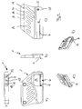
- the illustrated in the figures embodiment of a side mounting according to the present invention has a side plate 1 and a mounting plate 2 attached thereto.
- the mounting plate 2 is used for attachment, for example, a riflescope, not shown, and is provided in this embodiment with two mounting rings 3, which are bolted to the mounting plate 2 and are used in a known manner for receiving a riflescope.
- the side plate 1 on its inner, that is, not shown weapon side facing a dovetail-shaped in cross-section slit-like recess 4, which extends over the entire length of the side plate.
- the side plate 1 can be pushed onto a fastening profile arranged on the weapon, which is form-fitting and functionally complementary to the inner contour of the recess.
- an axial end 5 of the recess 4 is made wider.
- the side plate 1 At its outer side, that is to say away from the weapon, which is not shown, the side plate 1 is provided with a recess 6. This recess has a slot-like opening 7, which opens into the edge region of the recess 4.
- An L-shaped clamping jaw 8 is arranged substantially in a form-fitting manner in the recess 6.
- the clamping jaw 8 has a first leg 9, which is provided with a clamping edge 10.
- the jaw 8 is screwed against the side plate, the clamping edge 10, the slot-like opening 7 passes through and on Attachment profile of the weapon reaches the plant by clamping.
- a spring which is mounted with its two ends in corresponding holes 14 and 15 of the side plate and the jaw and causes the release of the fastening screws, not shown, opening the clamp or at least supported.
- the L-shaped clamping jaw 8 has a second leg 13, which has a considerably greater inner length L than the first leg 9.
- the leg 13 comes with its inner surface 15 on the surface 16 of the recess 6 of the side plate 1 to the plant and thus supports the side plate 1 against unwanted tilting.
- the leg 13 engages positively in the recess 6 of the side plate 1, so that the side edges of the leg 13 can come to rest on the side edges of the recess.
- the side plate 1 is provided in the region of its upper edge with two threaded bores 16 and 17. On the axis formed by these threaded holes three blind hole-like fitting holes 18, 19 and 20 are arranged between these two threaded holes, which serve alternatively to receive a dowel pin.
- the mounting plate 2 has an upper plate-shaped mounting portion 20 which is provided with through recesses 21 for fixing the mounting rings 3, other mounting elements or directly the additional device. Next, the mounting plate 2 on an angled portion 22, which serves to fasten the mounting plate 2 on the side plate 1.
- the angled portion 22 is provided with two through recesses 23 and 24, which serve to pass through the fastening screws, not shown.
- the two recesses 23 and 24 correspond in their arrangement to the threaded holes 16 and 17 of the side plate.
- the recesses 23 and 24 are formed differently on the side facing away from the side plate 1 inside of the region 22 of the mounting plate 2.
- the substantially cylindrically shaped recess 24 has on the inside of the region 22 a conical depression, while the slot-like in the vertical direction extending recess has a likewise slot-like depression.
- blind hole-like fitting holes 25, 26 and 27 are provided which have the same diameter as the fitting holes 18, 19 and 20 of the side plate. These passport holes serve alternatively for receiving a dowel pin, not shown. Similar to the fitting bores 18, 19 and 20, these fitting bores 25, 26 and 27 are also located on an axis passing through the center of the threaded bore 16.
- the two axes are at least slightly inclined to each other, so that three different pivot positions are adjustable by pivoting the mounting plate 2 relative to the side plate 1 and thus the two axes against each other about the through the attachment point threaded bore 16 / recess 24 formed pivot axis, in each of which a fitting bore the mounting plate is aligned with a mating hole of the side plate in registration, so that a dowel pin can be inserted into these aligned mating holes.
- the degree of inclination of the mounting plate relative to the side plate and thus the weapon can be preset precisely defined when screwing together mounting plate and side plate by selecting the holes in the dowel pin, each pair of mating holes corresponds to a specific shooting distance.
- a stop element 28 is provided which cooperates with a complementary stop on the weapon in the region of the fastening profile.
Abstract
Description
Die Erfindung betrifft eine Seitenmontage nach dem Oberbegriff des Patentanspruchs 1.The invention relates to a side mounting according to the preamble of
Seitenmontagen der hier in Rede stehenden Art dienen zur Befestigung von Zusatzeinrichtungen an einer Waffe. Zusatzeinrichtungen können dabei beispielsweise Beleuchtungseinrichtungen oder aber insbesondere Zieleinrichtungen, wie beispielsweise Zielfernrohre oder dergleichen, sein.Side mounts of the type in question here are used for attachment of additional equipment to a weapon. Additional devices may be, for example, lighting devices or in particular target devices, such as rifle scopes or the like.
Bei bestimmten Waffentypen ist die Befestigung derartiger Zusatzeinrichtungen an oder auf der Oberseite des Laufs oder des System- oder Verschlusskastens nicht möglich oder nicht gewünscht. Daher besteht die einzige weitere Möglichkeit darin, die gewünschte Zusatzeinrichtung über eine dafür geeignete Montagevorrichtung seitlich an einer der vorstehend genannten Waffenkomponenten anzubringen. Dazu weist die Waffe üblicherweise seitlich am Lauf, am Verschlussgehäuse oder am Systemkasten ein Befestigungsprofil, beispielsweise eine profilierte Führungsschiene, auf, auf das die Montagevorrichtung, in der eine dazu form- und/oder funktionskomplementäre Ausnehmung ausgebildet ist, aufschiebbar oder aufsteckbar ist und dort anschließend mit einer Klemmeinrichtung sicher befestigbar ist.For certain types of weapons, attachment of such accessories to or on top of the barrel or the system or closure box is not possible or desired. Therefore, the only other option is to attach the desired additional device laterally to one of the abovementioned weapon components via a suitable mounting device. For this purpose, the weapon usually on the side of the barrel, on the closure housing or on the system box, a fastening profile, for example a profiled guide rail, on which the mounting device, in which a form-and / or functionally complementary recess is formed, can be pushed or plugged and then securely fastened there with a clamping device.
Nachteilig bei diesen bekannten Seitenmontagen ist insbesondere, dass aufgrund des durch die einseitige Befestigung bei einer seitlichen Belastung der Zusatzeinrichtung auftretenden Momentes eine unerwünschte Veränderung der genauen Montageposition nicht zuverlässig ausgeschlossen werden kann, was zu einer Änderung der Treffpunktlage und damit zu Fehlschüssen führen kann.A disadvantage of these known side mounts is in particular that due to the occurring by the one-sided attachment at a lateral load of the accessory moment an unwanted change in the exact mounting position can not be reliably excluded, which can lead to a change in Treffpunktlage and thus to misses.
Ausgehend von diesem Stand der Technik ist es die Aufgabe der vorliegenden Erfindung, eine Seitenmontage der eingangs genannten Art zu schaffen, die eine zuverlässigere Befestigung einer Zusatzeinrichtung an einer Waffe ermöglicht.Based on this prior art, it is the object of the present invention to provide a side mounting of the type mentioned, which allows a more reliable attachment of an accessory to a weapon.
Diese Aufgabe wird durch einer Seitenmontage nach der Lehre des Anspruchs 1 gelöst.This object is achieved by a side mounting according to the teaching of
Vorteilhafte Ausgestaltungen der Erfindung sind Gegenstand der Unteransprüche.Advantageous embodiments of the invention are the subject of the dependent claims.
Eine Seitenmontage zur Befestigung einer Zusatzeinrichtung, insbesondere einer Zieleinrichtung, an einer Waffe weist in zunächst für sich bekannter Weise eine Seitenplatte zur Befestigung an der Waffe und eine Montageplatte zur Aufnahme der Zusatzeinrichtung auf. Zur Befestigung der Seitenplatte an der Waffe ist diese Waffe seitlich am Systemkasten, am Verschlussgehäuse oder am Lauf mit einem Befestigungsprofil versehen. In der Seitenplatte ist eine zu diesem Befestigungsprofil der Waffe form - und/oder funktionskomplementäre Ausnehmung derart ausgebildet, dass die Seitenplatte mit der Ausnehmung auf das Befestigungsprofil aufschiebbar und dort mit einer Klemmeinrichtung befestigbar ist.A side mounting for attaching an additional device, in particular a target device to a weapon has in a first known manner a side plate for attachment to the weapon and a mounting plate for receiving the auxiliary device. To attach the side plate to the weapon, this weapon is provided laterally on the system box, on the closure housing or on the barrel with a mounting profile. In the side plate to this attachment profile of the weapon form - and / or functionally complementary recess is formed such that the side plate with the recess on the mounting profile can be pushed and fastened there with a clamping device.
Erfindungsgemäß weist die Klemmeinrichtung eine im Wesentlichen L-förmige Klemmbacke auf. Der erste Schenkel der L-förmigen Klemmbacke ist dabei mit einer Klemmkante versehen, die mittels einer Schraubenanordnung, die den ersten Schenkel durchgreift und in die Seitenplatte eingreift, an das Befestigungsprofil lösbar anpressbar ist. Gleichzeitig ist dabei der zweite Schenkel der L-förmigen Klemmbacke an einer komplementären Anlagefläche der Seitenplatte zur Anlage bringbar.According to the invention, the clamping device has a substantially L-shaped clamping jaw. The first leg of the L-shaped jaw is provided with a clamping edge, which is releasably pressed by means of a screw arrangement which engages through the first leg and engages in the side plate, to the fastening profile. At the same time, the second leg of the L-shaped clamping jaw can be brought to rest on a complementary abutment surface of the side plate.
Mit anderen Worten bedeutet dies, dass das bei einer insbesondere seitlichen Belastung der Montagevorrichtung auftretende Moment nicht mehr nur über die durch die Schraubverbindung auf das Befestigungsprofil gepresste Klemmkante übertragen wird, sondern vielmehr zusätzlich eine Abstützung dieses Momentes über den zweiten Schenkel der L-förmigen Klemmbacke an der Anlagefläche der Seitenplatte erfolgt.In other words, this means that the moment occurring in particular lateral load of the mounting device is no longer transmitted only on the pressed by the screw on the mounting profile clamping edge, but rather additionally a support of this moment on the second leg of the L-shaped jaw the contact surface of the side plate takes place.
Nach einer bevorzugten Ausführungsform der Erfindung ist die Innenlänge des zweiten Schenkels größer als die Innenlänge des ersten Schenkels, wobei besonders bevorzugt die Innenlänge des zweiten Schenkels mindestens das Zweifache der Innenlänge des ersten Schenkels beträgt. Dadurch ergibt sich insgesamt eine besonders stabile Abstützung.According to a preferred embodiment of the invention, the inner length of the second leg is greater than the inner length of the first leg, wherein more preferably the inner length of the second leg is at least twice the inner length of the first leg. This results in a total of a particularly stable support.
In grundsätzlich beliebiger Weise kann die Abstützung des zweiten Schenkels auf der Außenseite der Seitenplatte erfolgen. Nach einem besonders bevorzugten Ausführungsbeispiel der Erfindung jedoch weist die Seitenplatte eine Ausnehmung auf, in der der zweite Schenkel im Wesentlichen formschlüssig geführt ist. Dadurch kann eine weitere Stabilisierung der Abstützung, insbesondere auch in der Ebene der Seitenplatte, erreicht werden.In principle, any way the support of the second leg can be done on the outside of the side plate. According to a particularly preferred embodiment of the invention, however, the side plate has a recess in which the second leg is guided substantially in a form-fitting manner. As a result, a further stabilization of the support, in particular in the plane of the side plate, can be achieved.
Die Seitenplatte und die Montageplatte können als einstückiges Bauteil ausgeführt sein. Nach einem bevorzugten Ausführungsbeispiel der Erfindung jedoch sind die beiden Platten als separate Bauteile ausgeführt, wobei die Montageplatte an der Seitenplatte lösbar befestigbar ist.The side plate and the mounting plate can be designed as a one-piece component. According to a preferred embodiment of the invention, however, the two plates are designed as separate components, wherein the mounting plate on the side plate is releasably fastened.
Vorzugsweise ist dabei die Montageplatte zumindest abschnittsweise im Wesentlichen L-förmig abgewinkelt, wobei der abgewinkelte Bereich form- und/oder kraftschlüssig an der Seitenplatte zur Anlage bringbar und dort befestigbar ist.Preferably, the mounting plate is at least partially angled substantially L-shaped, wherein the angled region positive and / or non-positive on the side plate can be brought to bear and fastened there.
Nach einem besonders bevorzugten Ausführungsbeispiel der Erfindung erfolgt die Befestigung der Montageplatte an der Seitenplatte mittels zweier in Laufrichtung der Waffe beabstandeter Befestigungsschrauben, die den L-förmig abgewinkelten Bereich der Montageplatte durchgreifen und in eine komplementäre Gewindebohrung in der Seitenplatte eingreifen. Dabei ist die die erste Befestigungsschraube als zentrierende Senkkopfschraube ausgeführt und greift mit ihrem Kopf zentrierend in eine komplementäre Einsenkung der Montageplatte ein. Die zweite Befestigungsschraube durchgreift die Montageplatte in einem sich quer zur Laufrichtung erstreckenden Langloch oder einem Loch mit größerem Durchmesser als der Schraubenschaft dieser Befestigungsschraube.According to a particularly preferred embodiment of the invention, the mounting of the mounting plate on the side plate by means of two spaced in the direction of the weapon mounting screws, which pass through the L-shaped angled portion of the mounting plate and engage in a complementary threaded hole in the side plate. Here, the first fastening screw is designed as a centering countersunk screw and engages with its head centering in a complementary depression of the mounting plate. The second fastening screw passes through the mounting plate in a slot extending transversely to the running direction or a hole with a larger diameter than the screw shaft of this fastening screw.
Dies bedeutet mit anderen Worten, dass, wenn die beiden Befestigungsschrauben leicht gelöst werden, durch die erste zentrierende Befestigungsschraube ein Schwenkgelenk gebildet wird, um das sich die Montageplatte gegenüber der Seitenplatte zumindest geringfügig schwenken lässt. Aufgrund des Langloches bzw. des Loches größeren Durchmessers in der Montageplatte bei der zweiten Befestigungsschraube wird diese Schwenkbewegung zugelassen. Wenn die gewünschte Winkelstellung erreicht ist, werden beide Befestigungsschrauben angezogen. Dadurch kann ohne jeden axialen Versatz eine reine Winkelverstellung der Montageplatte und damit beispielsweise eines darauf befestigten Zielfernrohres erfolgen. Somit kann in einfacher Weise eine Anpassung der Zielachse des Zielfernrohres an unterschiedliche Schussentfernungen erfolgen.This means, in other words, that when the two fastening screws are easily released, by the first centering mounting screw, a pivot joint is formed around which the mounting plate relative to the side plate can be at least slightly pivot. Due to the elongated hole or the hole of larger diameter in the mounting plate at the second mounting screw this pivoting movement is allowed. When the desired angular position is reached, both fixing screws are tightened. As a result, without any axial offset, a pure angular adjustment of the mounting plate and thus, for example, a riflescope mounted thereon can take place. Thus, an adjustment of the target axis of the riflescope at different shooting distances can be done in a simple manner.
Das nachfolgend erläuterte Ausführungsbeispiel entspricht im Wesentlichen dem vorstehend erläuterten Ausführungsbeispiel, wobei lediglich die Anordnung der Gewindebohrungen in der Montageplatte und dieThe embodiment explained below substantially corresponds to the embodiment explained above, wherein only the arrangement of the threaded holes in the mounting plate and the
Anordnung des Langloches und der zentrierenden Senkung in der Seitenplatte erfolgen. Nach diesem Ausführungsbeispiel erfolgt also die Befestigung der Montageplatte an der Seitenplatte mittels zweier in Laufrichtung der Waffe beabstandeter Befestigungsschrauben, die die Seitenplatte durchgreifen und in komplementäre Gewindebohrungen des L-förmig abgewinkelten Bereichs der Montageplatte eingreifen, wobei die erste Befestigungsschraube als zentrierende Senkkopfschraube ausgeführt ist, die in eine komplementäre Einsenkung der Seitenplatte eingreift, und die zweite Befestigungsschraube die Seitenplatte in einem sich quer zur Laufrichtung erstreckenden Langloch oder einem Loch mit größerem Durchmesser als der Schraubenschaft dieser Befestigungsschraube durchgreift.Arrangement of the elongated hole and the centering reduction in the side plate done. According to this embodiment, therefore, the attachment of the mounting plate takes place on the side plate by means of two in the running direction the weapon spaced mounting screws that pass through the side plate and engage in complementary threaded holes of the L-shaped angled portion of the mounting plate, wherein the first fastening screw is designed as a centering countersunk screw, which engages in a complementary recess of the side plate, and the second fastening screw, the side plate in one engages transversely to the direction extending slot or a hole with a larger diameter than the screw shaft of this fastening screw.
Um insbesondere die Genauigkeit der Winkelverstellung zwischen Seitenplatte und damit der Waffe bzw. deren Lauf einerseits und der Montageplatte und damit der darauf angeordneten Zieleinrichtung andererseits zu verbessern, ist nach einem weiteren Ausführungsbeispiel der Erfindung im Bereich zwischen den beiden Befestigungsschrauben in den zueinander weisenden Anlageflächen von Seitenplatte und Montageplatte mindestens jeweils eine Passbohrung ausgebildet, die einander so gegenüberliegen, dass ein Passstift gleichzeitig in zwei einander gegenüberliegende Passbohrungen von Seitenplatte und Montageplatte einsteckbar ist. Dadurch können genau definierte Winkelstellungen vorgegeben und eingehalten werden.In particular, to improve the accuracy of the angle adjustment between the side plate and thus the weapon or its run on the one hand and the mounting plate and thus the target device arranged thereon, according to a further embodiment of the invention in the region between the two mounting screws in the mutually facing contact surfaces of side plate and mounting plate formed at least one fitting bore, which are opposite to each other so that a dowel pin can be inserted simultaneously into two opposing fitting holes of side plate and mounting plate. As a result, precisely defined angular positions can be specified and maintained.
Besonders bevorzugt sind dabei in den zueinander weisenden Anlageflächen jeweils zumindest zwei in Laufrichtung beabstandete Passbohrungen angeordnet, wobei die erste Achse, auf der die Mittelpunkte der Passbohrungen der Seitenplatte liegen, und die zweite Achse, auf der die Mittelpunkte der Passbohrungen der Montageplatte liegen, zumindest geringfügig gegeneinander geneigt sind. Dadurch lassen sich mehrere vordefinierte Winkelstellungen zwischen Montageplatte und Seitenplatte bestimmen, die beispielsweise verschiedenen Schussentfernungen zugeordnet werden können.In each case, at least two fitting bores spaced apart in the running direction are particularly preferably arranged in the mutually facing contact surfaces, wherein the first axis, on which the centers of the fitting bores of the side plate lie, and the second axis, on which the centers of the fitting bores of the mounting plate lie, are at least slightly are inclined against each other. As a result, several predefined angular positions between mounting plate and side plate can be determined, which can be assigned, for example, to different shooting distances.
Im Folgenden wird die Erfindung anhand lediglich ein Ausführungsbeispiel zeigender Zeichnungen näher erläutert. Es zeigen:
- Fig. 1
- in seitlicher Ansicht von außen ein Ausführungsbeispiel einer erfindungsgemäßen Seitenmontage;
- Fig. 2
- in seitlicher Ansicht von innen das Ausführungsbeispiel nach
Fig. 1 ; - Fig. 3
- in Ansicht von hinten das Ausführungsbeispiel nach
Fig. 1 ; - Fig. 4
- die Seitenplatte der Seitenmontage des Ausführungsbeispiels nach
Fig. 1 ; - Fig. 5
- die Montageplatte der Seitenmontage des Ausführungsbeispiels nach
Fig. 1 ; und - Fig. 6
- die Klemmbacke der Seitenmontage des Ausführungsbeispiels nach
Fig. 1 .
- Fig. 1
- in side view from the outside an embodiment of a side mounting according to the invention;
- Fig. 2
- in lateral view from inside the embodiment according to
Fig. 1 ; - Fig. 3
- in view from behind the embodiment according to
Fig. 1 ; - Fig. 4
- the side plate of the side mounting of the embodiment according to
Fig. 1 ; - Fig. 5
- the mounting plate of the side mounting of the embodiment according to
Fig. 1 ; and - Fig. 6
- the jaw of the side mounting of the embodiment according to
Fig. 1 ,
Das in den Figuren dargestellte Ausführungsbeispiel einer Seitenmontage gemäß der vorliegenden Erfindung weist eine Seitenplatte 1 und eine daran befestigte Montageplatte 2 auf. Die Montageplatte 2 dient zur Befestigung beispielsweise eines nicht dargestellten Zielfernrohres und ist bei diesem Ausführungsbeispiel mit zwei Montageringen 3 versehen, die auf der Montageplatte 2 festgeschraubt sind und in bekannter Weise zur Aufnahme eines Zielfernrohres dienen.The illustrated in the figures embodiment of a side mounting according to the present invention has a
Wie insbesondere aus der
An ihrer äußeren, das heißt von der nicht dargestellten Waffe weg weisenden Seite ist die Seitenplatte 1 mit einer Ausnehmung 6 versehen. Diese Ausnehmung weist eine schlitzartige Öffnung 7 auf, die sich in den Randbereich der Ausnehmung 4 öffnet.At its outer side, that is to say away from the weapon, which is not shown, the
Eine L-förmige Klemmbacke 8 ist im Wesentlichen formschlüssig in der Ausnehmung 6 angeordnet. Die Klemmbacke 8 weist einen ersten Schenkel 9 auf, der mit einer Klemmkante 10 versehen ist. Mittels zweier nicht dargestellter Befestigungsschrauben, die den ersten Schenkel in jeweils einer Durchgangsbohrung 11 durchgreifen und in komplementäre Gewindebohrungen 12 in der Ausnehmung 6 der Seitenplatte 1 eingreifen, wird die Klemmbacke 8 gegen die Seitenplatte verschraubt, wobei die Klemmkante 10 die schlitzartige Öffnung 7 durchgreift und am Befestigungsprofil der Waffe klemmend zur Anlage gelangt.An L-shaped
Zwischen dem Schenkel 9 der Klemmbacke 8 und der Seitenplatte ist eine nicht dargestellte Feder angeordnet, die mit ihren beiden Enden in entsprechenden Bohrungen 14 und 15 der Seitenplatte bzw. der Klemmbacke gelagert ist und beim Lösen der nicht dargestellten Befestigungsschrauben ein Öffnen der Klemmung bewirkt oder zumindest unterstützt.Between the leg 9 of the clamping
Die L-förmige Klemmbacke 8 weist einen zweiten Schenkel 13 auf, der eine erheblich größere Innenlänge L als der erste Schenkel 9 aufweist. Der Schenkel 13 gelangt mit seiner Innenfläche 15 an der Fläche 16 der Ausnehmung 6 der Seitenplatte 1 zur Anlage und stützt die Seitenplatte 1 somit gegen ein unerwünschtes Verkippen ab. Gleichzeitig greift der Schenkel 13 formschlüssig in die Ausnehmung 6 der Seitenplatte 1 ein, so dass die Seitenkanten des Schenkels 13 an den Seitenkanten der Ausnehmung zur Anlage gelangen können. Dadurch erfolgt zum einen eine Führung der Klemmbacke 8 beim Festziehen der Klemmung und zum anderen können hier wiederum Kräfte und/oder Momente aufgenommen werden, die in der Ebene der Seitenplatte wirken.The L-shaped
Wie insbesondere aus der
Die Montageplatte 2 weist einen oberen plattenförmigen Montagebereich 20 auf, der mit durchgehenden Ausnehmungen 21 zur Befestigung der Montageringe 3, anderer Montagelemente oder unmittelbar der Zusatzeinrichtung versehen ist. Weiter weist die Montageplatte 2 einen abgewinkelten Bereich 22 auf, der zur Befestigung der Montageplatte 2 an der Seitenplatte 1 dient.The mounting
Wie insbesondere der
Aus der
Wie insbesondere der
Wie weiter insbesondere der
Claims (10)
dadurch gekennzeichnet,
dass die Klemmeinrichtung eine im Wesentlichen L-förmige Klemmbacke (8) aufweist, wobei der erste Schenkel (9) der L-förmigen Klemmbacke (8) eine Klemmkante (10) aufweist, die mittels einer Schraubenanordnung, die den ersten Schenkel (9) durchgreift und in die Seitenplatte (1) eingreift, an das Befestigungsprofil lösbar anpressbar ist, und wobei der zweite Schenkel (13) der L-förmigen Klemmbacke (8) an einer komplementären Anlagefläche (16) der Seitenplatte (1) zur Anlage bringbar ist.Side mounting for attaching an additional device, in particular a target device to a weapon with a side plate (1) for attachment to the weapon and a mounting plate (2) for receiving the attachment, wherein the weapon laterally on the system box, on the closure housing or on the barrel has a mounting profile in that the side plate (1) is provided with a recess (4) which is complementary in terms of shape and / or function, and wherein the side plate (1) with the recess (4) can be slid onto the fastening profile and fastened with a clamping device,
characterized,
in that the clamping device has a substantially L-shaped clamping jaw (8), wherein the first leg (9) of the L-shaped clamping jaw (8) has a clamping edge (10) which engages through the first leg (9) by means of a screw arrangement and in the side plate (1) engages, to the fastening profile is releasably pressed, and wherein the second leg (13) of the L-shaped jaw (8) on a complementary contact surface (16) of the side plate (1) can be brought into abutment.
dadurch gekennzeichnet,
dass die Innenlänge (L1) des zweiten Schenkels (13) größer als die Innenlänge (L2) des ersten Schenkels (9) ist.Side mounting according to claim 1,
characterized,
that the internal length (L1) of the second leg (13) is greater than the internal length (L2) of the first leg (9).
dadurch gekennzeichnet,
dass die Innenlänge (L2) des zweiten Schenkels (13) mindestens das Zweifache der Innenlänge (L1) des ersten Schenkels (9) beträgt.Side mounting according to claim 2,
characterized,
that the internal length (L2) of the second leg (13) at least two times the inner length (L1) of the first leg (9) is.
dadurch gekennzeichnet,
dass die Seitenplatte (1) eine Ausnehmung (6) aufweist, in der der zweite Schenkel im Wesentlichen formschlüssig geführt ist.Side mounting according to one of claims 1 to 3,
characterized,
in that the side plate (1) has a recess (6) in which the second leg is guided essentially in a form-fitting manner.
dadurch gekennzeichnet,
dass die Montageplatte (2) an der Seitenplatte (1) lösbar befestigbar ist.Side mounting according to one of claims 1 to 4,
characterized,
in that the mounting plate (2) can be detachably fastened to the side plate (1).
dadurch gekennzeichnet,
dass die Montageplatte (2) zumindest abschnittsweise im Wesentlichen L-förmig abgewinkelt ist und der abgewinkelte Bereich (22) form- und/oder kraftschlüssig an der Seitenplatte (1) zur Anlage bringbar und dort befestigbar ist.Side mounting according to claim 5,
characterized,
in that the mounting plate (2) is angled at least in sections substantially L-shaped and the angled region (22) can be brought into abutment with the form-fitting and / or force-locking manner on the side plate (1) and fastened there.
dadurch gekennzeichnet,
dass die Befestigung der Montageplatte (2) an der Seitenplatte (1) mittels zweier in Laufrichtung der Waffe beabstandeter Befestigungsschrauben erfolgt, die den L-förmig abgewinkelten Bereich (22) der Montageplatte durchgreifen und in komplementäre Gewindebohrung (16, 24) in der Seitenplatte (1) eingreifen, wobei die erste Befestigungsschraube als zentrierende Senkkopfschraube ausgeführt ist, die in eine komplementäre Einsenkung der Montageplatte (2) eingreift, und die zweite Befestigungsschraube die Montageplatte (2) in einem sich quer zur Laufrichtung erstreckenden Langloch (23) oder einem Loch mit größerem Durchmesser als der Schraubenschaft dieser Befestigungsschraube durchgreift.Side mounting according to claim 6,
characterized,
in that the attachment of the mounting plate (2) to the side plate (1) takes place by means of two fastening screws spaced apart in the direction of the weapon, which pass through the L-shaped angled region (22) of the mounting plate and into complementary threaded bore (16, 24) in the side plate (16). 1) engage, wherein the first fastening screw is designed as a centering countersunk screw, which engages in a complementary recess of the mounting plate (2), and the second fastening screw, the mounting plate (2) in a transverse to the running direction extending slot (23) or a hole with larger diameter than the screw shaft of this fastening bolt passes through.
dadurch gekennzeichnet,
dass die Befestigung der Montageplatte an der Seitenplatte mittels zweier in Laufrichtung der Waffe beabstandeter Befestigungsschrauben erfolgt, die die Seitenplatte durchgreifen und in komplementäre Gewindebohrungen des L-förmig abgewinkelten Bereichs der Montageplatte eingreifen, wobei die erste Befestigungsschraube als zentrierende Senkkopfschraube ausgeführt ist, die in eine komplementäre Einsenkung der Seitenplatte eingreift, und die zweite Befestigungsschraube die Seitenplatte in einem sich quer zur Laufrichtung erstreckenden Langloch oder einem Loch mit größerem Durchmesser als der Schraubenschaft dieser Befestigungsschraube durchgreift.Side mounting according to claim 6,
characterized,
in that the attachment of the mounting plate to the side plate takes place by means of two fastening screws spaced apart in the direction of the weapon, which engage through the side plate and engage in complementary threaded bores of the L-shaped angled region of the mounting plate, wherein the first fastening screw is designed as a centering countersunk screw, which in a complementary Engages depression of the side plate, and the second fastening screw passes through the side plate in a transverse to the direction extending slot or a hole with a larger diameter than the screw shaft of this fastening screw.
dadurch gekennzeichnet,
dass im Bereich zwischen den beiden Befestigungsschrauben in den zueinander weisenden Anlageflächen von Seitenplatte (1) und Montageplatte (2) mindestens jeweils eine Passbohrung (18, 19, 20; 25, 26, 27) ausgebildet ist, die einander so gegenüberliegen, dass ein Passstift in zwei einander gegenüberliegende Passbohrungen von Seitenplatte (1) und Montageplatte (2) einsteckbar ist.Side mounting according to claim 7 or 8,
characterized,
in that at least one respective fitting bore (18, 19, 20, 25, 26, 27) is formed in the region between the two fastening screws in the mutually facing abutment surfaces of side plate (1) and mounting plate (2), which face each other such that a dowel pin in two opposite fitting holes of side plate (1) and mounting plate (2) can be inserted.
dadurch gekennzeichnet,
dass in den zueinander weisenden Anlageflächen jeweils zumindest zwei in Laufrichtung beabstandete Passbohrungen (18, 19, 20; 25, 26, 27) angeordnet sind, wobei die erste Achse, auf der die Mittelpunkte der Passbohrungen 18, 19, 20) der Seitenplatte (1) liegen und die zweite Achse, auf der die Mittelpunkte der Passbohrungen (25, 26, 27) der Montageplatte (2) liegen, zumindest geringfügig gegeneinander geneigt sind.Side mounting according to claim 9,
characterized,
that in the facing bearing surfaces each have at least two in the running direction of spaced fitting bores (18, 19, 20; 27 25, 26) are arranged, wherein the first axis on which the centers of the fitting holes 18, 19, 20) of the side plate (1 ) lie and the second axis, on which the centers of the fitting holes (25, 26, 27) of the mounting plate (2) are at least slightly inclined to each other.
Applications Claiming Priority (1)
| Application Number | Priority Date | Filing Date | Title |
|---|---|---|---|
| DE201310003908 DE102013003908A1 (en) | 2013-03-08 | 2013-03-08 | Side mounting for attaching an accessory to a weapon |
Publications (1)
| Publication Number | Publication Date |
|---|---|
| EP2775254A1 true EP2775254A1 (en) | 2014-09-10 |
Family
ID=50193269
Family Applications (1)
| Application Number | Title | Priority Date | Filing Date |
|---|---|---|---|
| EP14156981.4A Withdrawn EP2775254A1 (en) | 2013-03-08 | 2014-02-27 | Side mounting for fixing an additional device to a weapon |
Country Status (3)
| Country | Link |
|---|---|
| EP (1) | EP2775254A1 (en) |
| DE (1) | DE102013003908A1 (en) |
| RU (1) | RU2014108446A (en) |
Cited By (1)
| Publication number | Priority date | Publication date | Assignee | Title |
|---|---|---|---|---|
| US20180195838A1 (en) * | 2017-01-10 | 2018-07-12 | Midwest Industries, Inc. | Firearm accessory interchangeable mount system |
Citations (5)
| Publication number | Priority date | Publication date | Assignee | Title |
|---|---|---|---|---|
| AU1760767A (en) * | 1968-01-31 | 1969-08-07 | Rifle sight mount | |
| US4367606A (en) * | 1980-10-06 | 1983-01-11 | Bechtel Daniel L | Mount for rifle telescope sight |
| TWM288680U (en) * | 2005-10-04 | 2006-03-11 | Yau-Shi Shiu | Improved clamp structure for firearms accessories |
| US20080072471A1 (en) * | 2006-02-08 | 2008-03-27 | Da Keng | Removable optical sight mount adapted for use with M14, M1A and similar rifles and method for removably attaching an optical sight to a rifle |
| EP2345864A2 (en) * | 2010-01-19 | 2011-07-20 | Innovative Wireless Technologies, Inc. | Smart tactical flashlight |
Family Cites Families (6)
| Publication number | Priority date | Publication date | Assignee | Title |
|---|---|---|---|---|
| DE29616697U1 (en) * | 1996-09-25 | 1996-12-05 | Apel Ernst Gmbh | Rifle scope mount adapter |
| DE20101903U1 (en) * | 2001-01-25 | 2001-05-03 | Apel Ernst Gmbh | Split target holder |
| US7188978B2 (en) * | 2004-11-15 | 2007-03-13 | Streamlight, Inc. | Light mountable on a mounting rail |
| ITRM20070566A1 (en) * | 2007-10-29 | 2009-04-30 | Fabio Freddara | PRECISION SUPPORT FOR RAPID ATTACHMENT TO AN ARMA |
| US8397421B2 (en) * | 2010-04-08 | 2013-03-19 | Leapers, Inc. | Quick disconnect apparatus, assembly and method for utilizing the same |
| DE202011100438U1 (en) * | 2011-05-07 | 2011-07-04 | Sitec Präzisionstechnik Handels- und Produktionsgesellschaft mbH, 70825 | Housing of a machine gun |
-
2013
- 2013-03-08 DE DE201310003908 patent/DE102013003908A1/en not_active Withdrawn
-
2014
- 2014-02-27 EP EP14156981.4A patent/EP2775254A1/en not_active Withdrawn
- 2014-03-05 RU RU2014108446/11A patent/RU2014108446A/en not_active Application Discontinuation
Patent Citations (5)
| Publication number | Priority date | Publication date | Assignee | Title |
|---|---|---|---|---|
| AU1760767A (en) * | 1968-01-31 | 1969-08-07 | Rifle sight mount | |
| US4367606A (en) * | 1980-10-06 | 1983-01-11 | Bechtel Daniel L | Mount for rifle telescope sight |
| TWM288680U (en) * | 2005-10-04 | 2006-03-11 | Yau-Shi Shiu | Improved clamp structure for firearms accessories |
| US20080072471A1 (en) * | 2006-02-08 | 2008-03-27 | Da Keng | Removable optical sight mount adapted for use with M14, M1A and similar rifles and method for removably attaching an optical sight to a rifle |
| EP2345864A2 (en) * | 2010-01-19 | 2011-07-20 | Innovative Wireless Technologies, Inc. | Smart tactical flashlight |
Non-Patent Citations (3)
| Title |
|---|
| "MI AK Side Railed Scope Mount", XP002726084, Retrieved from the Internet <URL:https://web.archive.org/web/20130119190856/http://midwestindustriesinc.com/index.cfm?fuseaction=category.display&category_id=433> [retrieved on 20140602] * |
| ANONYMOUS: "AK Side Railed Scope Mount", 19 January 2013 (2013-01-19), XP002725210, Retrieved from the Internet <URL:http://www.midwestindustriesinc.com/index.cfm?fuseaction=category.display&category_ID=433> [retrieved on 20140602] * |
| ANONYMOUS: "IMAGE from Product: MIDWEST INDUSTRIES, INC. - AK-47/74 SCOPE MOUNT", XP002726083, Retrieved from the Internet <URL:http://www.brownells.com/userdocs/products/t_100009103_5..jpg> [retrieved on 20140602] * |
Cited By (2)
| Publication number | Priority date | Publication date | Assignee | Title |
|---|---|---|---|---|
| US20180195838A1 (en) * | 2017-01-10 | 2018-07-12 | Midwest Industries, Inc. | Firearm accessory interchangeable mount system |
| US10670374B2 (en) * | 2017-01-10 | 2020-06-02 | Midwest Industries, Inc. | Firearm accessory interchangeable mount system |
Also Published As
| Publication number | Publication date |
|---|---|
| DE102013003908A1 (en) | 2014-09-11 |
| RU2014108446A (en) | 2015-10-27 |
Similar Documents
| Publication | Publication Date | Title |
|---|---|---|
| EP2339287B1 (en) | Clamping system for accessories on a Picatinny rail | |
| DE102011013575B4 (en) | Device for attaching an attachment to a firearm | |
| EP1380807B1 (en) | Connecting device for mounting a telescopic sight on a fire arm | |
| EP3472403B1 (en) | Device for fastening a panel-shaped component in a receiving groove of a carrying rail | |
| WO2016146218A1 (en) | Door hinge or window hinge | |
| EP3064823B1 (en) | Quick-acting clamping device for self-closing holding of a counterpiece | |
| EP2118416A1 (en) | Device with a mounting insert for fastening fitting parts to hollow profiles and method for attaching said mounting insert to the hollow profile | |
| EP1382784B1 (en) | Fitting for an aluminium window shutter | |
| DE102005014121A1 (en) | Carrier tool for die plate with two cutting edges, e.g. for lathe tool, has edges of receptacle in symmetrical sections, enclosing non-zero angle | |
| EP2775254A1 (en) | Side mounting for fixing an additional device to a weapon | |
| EP1813824A2 (en) | Connection device for furniture panels | |
| EP2245412B1 (en) | Device for fastening an added part, particularly a sighting mechanism, to a weapon | |
| EP3219891A1 (en) | Three-dimensionally adjustable hinge system | |
| EP3029241A1 (en) | Corner fitting with increased clamping force | |
| DE102014217781A1 (en) | Device for fastening a cladding element | |
| DE102014004643A1 (en) | Tape hub | |
| DE10240793A1 (en) | sliding block | |
| DE202010000291U1 (en) | Tape flap device | |
| DE102018101285A1 (en) | Corner connector | |
| EP2514892B1 (en) | System for attaching a fitting part | |
| EP2540942B1 (en) | Adjustable fitting assembly | |
| EP2394131B1 (en) | Apparatus for fastening an additional device to a weapon | |
| DE202005006591U1 (en) | Carrier tool for die plate with two cutting edges, e.g. for lathe tool, has edges of receptacle in symmetrical sections, enclosing non-zero angle | |
| EP3168405B1 (en) | Frame structure for a sliding door | |
| DE102013103460B4 (en) | Device for crossing traffic signs |
Legal Events
| Date | Code | Title | Description |
|---|---|---|---|
| PUAI | Public reference made under article 153(3) epc to a published international application that has entered the european phase |
Free format text: ORIGINAL CODE: 0009012 |
|
| 17P | Request for examination filed |
Effective date: 20140227 |
|
| AK | Designated contracting states |
Kind code of ref document: A1 Designated state(s): AL AT BE BG CH CY CZ DE DK EE ES FI FR GB GR HR HU IE IS IT LI LT LU LV MC MK MT NL NO PL PT RO RS SE SI SK SM TR |
|
| AX | Request for extension of the european patent |
Extension state: BA ME |
|
| STAA | Information on the status of an ep patent application or granted ep patent |
Free format text: STATUS: THE APPLICATION IS DEEMED TO BE WITHDRAWN |
|
| 18D | Application deemed to be withdrawn |
Effective date: 20150311 |