EP2775075A2 - Türaußengriffanordnung - Google Patents
Türaußengriffanordnung Download PDFInfo
- Publication number
- EP2775075A2 EP2775075A2 EP14156821.2A EP14156821A EP2775075A2 EP 2775075 A2 EP2775075 A2 EP 2775075A2 EP 14156821 A EP14156821 A EP 14156821A EP 2775075 A2 EP2775075 A2 EP 2775075A2
- Authority
- EP
- European Patent Office
- Prior art keywords
- door
- handle
- outside
- handle assembly
- housing
- Prior art date
- Legal status (The legal status is an assumption and is not a legal conclusion. Google has not performed a legal analysis and makes no representation as to the accuracy of the status listed.)
- Granted
Links
Images



Classifications
-
- E—FIXED CONSTRUCTIONS
- E05—LOCKS; KEYS; WINDOW OR DOOR FITTINGS; SAFES
- E05B—LOCKS; ACCESSORIES THEREFOR; HANDCUFFS
- E05B77/00—Vehicle locks characterised by special functions or purposes
- E05B77/34—Protection against weather or dirt, e.g. against water ingress
-
- E—FIXED CONSTRUCTIONS
- E05—LOCKS; KEYS; WINDOW OR DOOR FITTINGS; SAFES
- E05B—LOCKS; ACCESSORIES THEREFOR; HANDCUFFS
- E05B77/00—Vehicle locks characterised by special functions or purposes
- E05B77/36—Noise prevention; Anti-rattling means
-
- E—FIXED CONSTRUCTIONS
- E05—LOCKS; KEYS; WINDOW OR DOOR FITTINGS; SAFES
- E05B—LOCKS; ACCESSORIES THEREFOR; HANDCUFFS
- E05B79/00—Mounting or connecting vehicle locks or parts thereof
- E05B79/02—Mounting of vehicle locks or parts thereof
- E05B79/06—Mounting of handles, e.g. to the wing or to the lock
-
- E—FIXED CONSTRUCTIONS
- E05—LOCKS; KEYS; WINDOW OR DOOR FITTINGS; SAFES
- E05B—LOCKS; ACCESSORIES THEREFOR; HANDCUFFS
- E05B85/00—Details of vehicle locks not provided for in groups E05B77/00 - E05B83/00
- E05B85/10—Handles
- E05B85/14—Handles pivoted about an axis parallel to the wing
- E05B85/18—Handles pivoted about an axis parallel to the wing a longitudinal grip part being pivoted about an axis parallel to the longitudinal axis of the grip part
Definitions
- the invention is directed to an outside door handle assembly of a motor vehicle having a fastened to the inside of the door handle support, a pivotally mounted on the handle support member and from the outside of the door by a door outlet mountable and in the assembled state to the handle support extending trough housing.
- An outside door handle assembly of the type described is, for example, from the DE 101 09 106 A1 Known and comprising a fastened to an inside of a door handle carrier which has a receptacle for a cooperating with the lock cylinder lock cylinder, and a handle recess assembly which is mountable from the outside of the door through a door outbreak into a recess in the handle support and one of the On the outside of the door operable handle element rotatably supports.
- the invention has for its object to provide a solution that provides a structurally simple manner and cost, an improved exterior door handle assembly in which the noise propagation is reduced from the outside of the vehicle into the vehicle interior to a minimum and through which the aeroacoustics of the outside door handle assembly the growing comfort awareness of Driver and user.
- an attachable to the handle support and cup-shaped housing member is provided which forms an accessible from the outside of the door and hermetically sealed to the inside of the door operating space together with the handle support and the well housing, in which the operable from the outside of the door handle element is arranged in the assembled state of the door outer handle assembly.
- the invention provides a door outer handle arrangement in a structurally simple manner, which is distinguished by improved aeroacoustic properties.
- the space on the side of the inside of the door is hermetically sealed from the operating room, which is accessible from the outside of the door and thus exposed to weathering, whereby the invention provides an outside door handle assembly that meets high comfort requirements and the vehicle interior windproof against the Screen outside.
- the operating space communicating with the vehicle exterior side is hermetically sealed to the inside of the door, so that neither sound nor weather influences can spread beyond the operating space into the interior of the vehicle.
- the exterior door handle arrangement reduces annoying, aerodynamically generated noises, such as occur when the vehicle flows around during travel, and thereby prevents undesired propagation of sound into the interior of the motor vehicle.
- the invention provides in an advantageous embodiment, that to form the operating space a from the trough housing formed end edge and formed by the handle support contour edge sealingly abut against a bearing edge formed by the housing element.
- the operating space in which the handle element which can be actuated from the vehicle exterior is thus arranged is not formed by a single component, but consists of several components, which ultimately contributes to the modular construction of the outside door handle device and the accessibility to the operating space and the assembly the grip element simplified by first the handle element and the handle support can be mounted before the operating space is completed, which is only the case when the housing element is mounted from the inside of the door to the handle support and the trough housing is mounted from the outside of the door ,
- the handle carrier and / or the housing element can not always be ensured that their respective edges are arranged in wind-tight manner one above the other, the invention provides in an embodiment that between the End edge of the trough housing, the contour edge of the handle support and the bearing edge of the housing member at least one, preferably elastically formed, sealing element is arranged.
- the sealing element may in this case be weather-resistant, for example, to be resistant to moisture.
- TPV thermoplastic vulcanizate with a high resistance to environmental influences.
- the invention provides, in an advantageous embodiment, that the sealing element has, at least in sections, a compression projection protruding from its core cross-section.
- the compression projection is compressed in its installed position between the edges of the trough housing, handle carrier and / or housing element and reinforced due to its compression, the seat of the sealing element.
- the gripping element has at least one lever arm, the free end of which is pivotably mounted on the handle carrier outside the operating space.
- the arranged in the operating space handle member is thus not stored in the operating space, even if the arrangement and operation of the handle member are provided in the operating space.
- the storage of the at least one lever arm is rather provided outside of the operating space, so that the storage against the effects of weather, which act within the operating space, is arranged protected. This can increase the life of the storage, but at least reduces the susceptibility to storage.
- the invention advantageously provides that the at least one lever arm of the gripping element extends through a through opening formed in the operating space.
- the passage opening may in this case be formed in the housing element and / or in the carrier element and / or in the trough housing, wherein expediently provided for a lever arm passage opening is formed in the upper shell-like housing member.
- the invention further provides, in an embodiment, for the at least one lever arm of the grip element to be arranged in the operating space in the installed state of the outside door handle arrangement Has cross-sectional thickening, which rests in the unactuated state of the handle member hermetically sealed at the edge of the passage opening of the operating space.
- the lever arm must functionally have a smaller cross-section than the passage opening of the operating space, so that a movement of the handle member when it is actuated at all possible.
- the invention provides in a further embodiment that a lever arm sealing element along the edge of the passage opening of the operating space is provided.
- the lever arm or its cross-sectional thickening is in a sealing manner on the lever arm sealing element, so that created by trough housing, handle support and housing element operating space is formed windproof against the inside of the door, causing wind noise and weathering does not affect the operating space beyond the vehicle interior can affect.
- a thermoplastic vulcanizate TPV can also be used as the exemplary material for the lever arm sealing element.
- the invention provides in a further embodiment that the lever arm sealing element and the sealing element are formed as a single sealing component.
- This one sealing member i. the one-piece design of sealing element and lever arm sealing element can then be produced inexpensively in a single manufacturing process, wherein the assembly of the one sealing component per outside door handle assembly compared to two components intended for sealing fails easier and more time-saving.
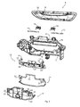
- FIG. 1 is a perspective view of an outside door handle assembly 1 according to the invention shown in disassembled state.
- the outside door handle assembly 1 is intended for a door 2 of a motor vehicle and comprises a handle support 3, which is fastened to the inside of the door 4, and a trough housing 5, which is mountable from the outside of the door 6.
- a handle support 3 For attachment of the handle support 3 on the inside of the door 4, this has in the illustrated embodiment, two mounting lugs 7, for example, hold the head of a screwing, which in turn is in engagement with the handle support 3. In this way, when mounting the outside door handle assembly 1, the handle support 3 is stably screwed to the inside of the door 4.
- the trough housing 5 is then inserted through a door outlet 8 from the outside of the door 6 in the door 2 and is then flush with its outer edge portion 30 on the outside door 6 on.
- the trough housing 5 extends in the assembled state to the handle support 3 and is partially inserted in an opening 9 formed in the handle support 3.
- FIG. 2 shows the trough housing 5 and the handle support 3 in an enlarged view, wherein moreover a lock cylinder 10 is shown for mechanical opening of the corresponding door lock.
- the lock cylinder 10 can be fastened detachably by means of a bayonet connection to the handle support 3, as in FIG FIG. 1 is shown.
- further components can be attached to the handle support, as follows with additional reference to the FIGS. 3 to 8 is described.
- FIG. 4 shows the handle support 3 from FIG. 2 in a rear view, in which the lock cylinder 10 is omitted.
- the lock cylinder 10 is omitted.
- FIG. 4 It can be seen that on the handle support 3 in the upper region of a housing member 11 is mounted, which in the front views of the handle support in the Figures 1 and 2 can not be seen.
- the housing element 11 is mounted in the assembled state of the door outer handle assembly 1 on the side facing away from the inside of the door 4 of the handle support 3 on the handle support 3.
- FIG. 3 the essential components of the outside door handle assembly 1 are shown in a single part view, with only the trough housing 5 from the outside of the door 6 is mountable. All other components of the outside door handle assembly 1 are mounted on the door inner side 4 of the motor vehicle door 2 via the handle support 3, which can be attached directly to the inside of the door 4, for example by means of a screw connection. To the mountable on the handle support 3 components are with reference to FIG. 3 to count a pivotally mounted on the handle support 3 handle member 12.
- the grip element 12 is further in the sectional view in FIG FIG. 6 whereas the gripping element 12 can be seen in the Figures 1 and 2 from the handle carrier 3 and in FIG. 3 is covered by the housing member 11.
- the handle member 12 For the pivotable mounting of the handle member 12, the handle member 12 at its two longitudinal ends in each case a lever arm 13, whose respective free end 14 is rotatably connected to a corresponding pivot axis 15, whereby the handle member 12 to a horizontal axis is pivotable.
- the grip element 12 may be coupled to a mechanical lever system for the mechanical opening of the motor vehicle door 2. Alternatively or additionally, the grip element 12 may also be connected to a system for electrically opening the motor vehicle door 2. Constructive measures for the mechanical and electrical opening of motor vehicle doors 2 are known from the prior art, so apart from details of these options.
- the respective pivot axes 15 of the grip element 12 extend from a pushbutton 31 serving to actuate the opening mechanism and are rotatably mounted on the upper side 32 of the handle support 3.
- the respective lever arm 13 is rotatably connected to the corresponding pivot axis 15.
- a spring element 16 supported on the upper side 32 of the handle support 12 is provided on each pivot axis 15, so that the grip element 12 has to be deflected against the force of the spring elements 16 in order to effect a door opening operation.
- the respective spring element 16 thus ensures that the grip element 12 is shifted back into its unactuated starting position as soon as the actuation process is completed and no force is exerted on the grip element 12.
- the operation of the handle member 12 is carried out in the illustrated embodiment of the door outside 6 by a user actuates the handle member 12 through an opening formed in the trough 5 access opening 35 therethrough by the push button 31 is pulled to the outside of the door 6.
- the gripping element 12 is covered above and in part towards the door outlet 8 from the upper side 32 of the handle carrier 3, whereas the gripping element 12 is encapsulated towards the bottom and partially in the direction away from the inside of the door 4 from the bowl-shaped well housing 5.
- the housing element 11 is in the case of the exterior door handle arrangement 1 according to the invention provided, wherein the housing member 11 is attachable to the handle support 3.
- the bowl-shaped bowl housing 5, the handle support 3 and the shell-shaped housing member 11 form an operating space 17.
- the operating space 17 is accessible only from the outside of the door 6 and receives the handle member 12.
- trough housing 5 and the housing element 11 actuating space 17 is formed such that it is hermetically sealed against the inside of the door 4.
- the operating space 17 is a kind of cavity, which only in the sectional view of FIG. 6 is apparent.
- the housing element 11 forms together with the handle support 3 and the well housing 5 exclusively from the outside door 6 from accessible and hermetically sealed to the inside of the door 4 operating space 17, which from the outside of the door 6 from operable handle member 12 housed and arranged in the assembled state in the operating space 17.
- the disassembly of the housing element 11 allows access to the operating space 17 from the inside of the door 4.
- the hermetic sealing of the operating space 17 is facilitated by the fact that for forming the operating space 17, a terminal edge 18 formed by the trough housing 5 and a contour edge 19 formed by the handle support 3 abut sealingly against a support rim 20 formed by the housing element 11.
- the contiguous edges 18, 19 and 20 are in FIG. 3 for the individual components of the outside door handle assembly 1 and in the FIGS. 5 and 6 showing various sectional views of the outside door handle assembly 1 in the assembled state, can be seen. As in particular the sectional views of FIGS.
- a sealing element 21 is disposed between the end edge 18 of the trough housing 5, the contour edge 19 of the handle support 3 and the support edge 20 of the housing member 11 to increase the hermetic seal of the operating space 17 to the inside of the door 4.
- the sealing element 21, which may consist of a thermoplastic vulcanizate (TPV), is substantially modeled on the contour of the support rim 20 of the housing element 11.
- TPV thermoplastic vulcanizate
- the sealing element 21 is designed in the manner of a sealing ring and follows the outer edge contour of the housing element 11, in particular the support rim 20 of the housing element 11.
- the sealing element 21 has a compression projection 22 which protrudes from the core cross section 23 of the sealing element 21.
- This compression lug 22 is particularly evident in FIG. 8 to recognize.
- the compression projection 22 is only partially formed on the sealing element 21.
- the compression projection 22 of the sealing element 21 is provided only for the portion of the superimposed edges 18 and 20 of trough housing 5 and housing element 11.
- the grip element 3 has two lever arms 13, the free ends 14 of which are pivotably mounted on the handle carrier 3 outside the operating space 17.
- the respective lever arms 13 of the gripping element 12 each extend through a through opening 24 formed in the operating space 17.
- the respective through holes 24 are formed in the housing member 11.
- the lever arms 13 have a cross-sectional thickening 25, which bears in the unactuated state of the handle member 12 sealingly on the edge 26 of the through hole 24 of the actuating chamber 17, as in FIG. 6 is shown in sectional view.
- the collar-shaped cross-sectional thickening 25 of the respective lever arms 13 does not rest directly on the edge 26 of the respective passage opening 24. Rather, a corresponding Hebelarmdichtungselement 27 is provided between the edge 26 of the respective passage opening 24 and the respective cross-sectional thickening 25 of the corresponding lever arm 13, which is disposed along the edge 26 of the passage opening 24 of the operating space 17.
- the lever arm sealing element 27 is designed as part of the sealing element 21.
- the sealing member 21 and the lever arm sealing member 27 is integrally formed as a single sealing member 33, in particular the Figures 3 . 7 and 8 can be seen.
- the sealing element 21 integrally formed thereon lever arm sealing member 27 seals the actuating chamber 17 relative to the mounting of the handle member 12 by the cross-sectional thickening 25 of the respective lever arm 13 presses against the corresponding Hebelarmdichtungselement 27 in the unactuated state of the handle member 12, wherein the pressure effect supported by the spring elements 16 is, so that the cross-sectional thickening 25 is always urged with a certain force in the direction of the edge 26 of the through hole 24.
- the operating space 17 is formed in the illustrated embodiment of the handle support 3, trough housing 5 and the housing member 11, all at least each sections have a cup-shaped and matched shape.
- the handle support 3 and the housing element 11 form the upper portion of the operating space 17, whereas the trough housing 5 defines the lower portion of the operating space 17.
- the handle support 3 and the housing member 11 are designed as a one-piece component and define the upper portion of the operating space 17, but this is contrary to the modular structure of the outside door handle assembly 1 and the attachment of the Handle element 12 and access to the handle member 12 could complicate.
- the invention described above is not limited to the described and illustrated embodiment.
- the grip element 12 may be mounted on only a single pivot axis 15. It will be appreciated that numerous modifications which are obvious to a person skilled in the art according to the intended application can be made to the embodiment shown in the drawing without departing from the scope of the invention. It belongs to the invention, all that which is contained in the description and / or shown in the drawing, including what, in deviation from the concrete embodiment obvious to those skilled.
Landscapes
- Lock And Its Accessories (AREA)
Abstract
Description
- Die Erfindung richtet sich auf eine Türaußengriffanordnung eines Kraftfahrzeugs, die einen an der Türinnenseite befestigbaren Griffträger, ein an dem Griffträger schwenkbar gelagertes Griffelement und ein von der Türaußenseite durch einen Türausbruch hindurch montierbares und sich im montierten Zustand bis zum Griffträger erstreckendes Muldengehäuse aufweist.
- Eine Türaußengriffanordnung der eingangs bezeichneten Art ist beispielsweise aus der
DE 101 09 106 A1 bekannt und umfasst einen an einer Innenseite einer Tür befestigbaren Griffträger, welcher eine Aufnahme für einen mit dem Türschloss zusammenwirkenden Schließzylinder besitzt, und eine Griffmulden-Baueinheit, die von Außenseite der Tür durch einen Türausbruch in einen Ausschnitt im Griffträger montierbar ist und die ein von der Türaußenseite betätigbares Griffelement drehbar lagert. Bei dieser bekannten Türaußengriffanordnung, bei der das Griffelement als Ziehgriff ausgebildet ist, sind keine besonderen baulichen Maßnahmen vorgesehen, um eine Ausbreitung von Außengeräuschen des Kraftfahrzeugs in das Fahrzeuginnere zu unterbinden oder zu minimieren, so dass sich die durch die aerodynamische Umströmung des Kraftfahrzeugs erzeugten Geräusche durch den Türausbruch der Türaußengriffanordnung hindurch in das Fahrzeuginnere ausbreiten können, was zu Komforteinbußen für den Fahrzeugführer führt. - Der Erfindung liegt die Aufgabe zugrunde eine Lösung zu schaffen, die auf konstruktiv einfache Weise und kostengünstig eine verbesserte Türaußengriffanordnung bereitstellt, bei welcher die Geräuschfortpflanzung von außerhalb des Kraftfahrzeugs in das Fahrzeuginnere auf ein Minimum reduziert ist und durch welche die Aeroakustik der Türaußengriffanordnung dem wachsenden Komfortbewusstsein der Fahrzeugführer und Benutzer gerecht wird.
- Bei einer Türaußengriffanordnung der eingangs bezeichneten Art wird die Aufgabe erfindungsgemäß dadurch gelöst, dass ein an dem Griffträger anbringbares und schalenförmig ausgebildetes Gehäuseelement vorgesehen ist, welches zusammen mit dem Griffträger und dem Muldengehäuse einen von der Türaußenseite zugänglichen und zur Türinnenseite hermetisch abgedichteten Betätigungsraum ausbildet, in welchem das von der Türaußenseite aus betätigbare Griffelement im zusammengebauten Zustand der Türaußengriffanordnung angeordnet ist.
- Vorteilhafte und zweckmäßige Ausgestaltungen und Weiterbildungen der Erfindung ergeben sich aus den Unteransprüchen.
- Durch die Erfindung wird auf konstruktiv einfache Weise eine Türaußengriffanordnung bereitgestellt, die sich durch verbesserte aeroakustische Eigenschaften auszeichnet. Der Raum auf der Seite der Türinnenseite ist von dem Betätigungsraum, welcher von der Türaußenseite aus zugänglich ist und damit Witterungseinflüssen ausgesetzt ist, hermetisch abgedichtet, wodurch durch die Erfindung eine Türaußengriffanordnung zur Verfügung gestellt wird, die hohen Komfortansprüchen gerecht wird und das Fahrzeuginnere winddicht gegenüber der Türaußenseite abschirmt. Anders ausgedrückt ist der mit der Fahrzeugaußenseite in Verbindung stehende Betätigungsraum zur Türinnenseite hin hermetisch abgedichtet, so dass weder Schall noch Witterungseinflüsse sich über den Betätigungsraum hinaus in das Fahrzeuginnere ausbreiten können. Insbesondere reduziert die Türaußengriffanordnung aufgrund der hermetischen Abdichtung des Betätigungsraumes gegenüber dem Fahrzeuginneren störende, aerodynamisch erzeugte Geräusche, wie sie bei der Umströmung des Fahrzeugs während der Fahrt entstehen, und verhindert dadurch eine unerwünschte Schallausbreitung in das Innere des Kraftfahrzeugs.
- Für einen modularen Aufbau der Türaußengriffvorrichtung, zum Beispiel zum Zwecke der Vereinfachung von Reparaturarbeiten, damit das Griffelement von der Türinnenseite aus leicht zugänglich ist, sieht die Erfindung in vorteilhafter Ausgestaltung vor, dass zur Bildung des Betätigungsraumes ein vom Muldengehäuse ausgebildeter Abschlussrand und ein vom Griffträger ausgebildeter Konturenrand an einem vom Gehäuseelement ausgebildeten Auflagerand abdichtend anliegen. Der Betätigungsraum, in dem das von der Fahrzeugaußenseite aus betätigbare Griffelement angeordnet ist, ist somit nicht von einem einzigen Bauteil gebildet, sondern setzt sich aus mehreren Bauteilen zusammen, was letztlich zu dem modularen Aufbau der Türaußengriffvorrichtung beiträgt und die Zugänglichkeit zu dem Betätigungsraum sowie die Montage des Griffelements vereinfacht, indem zunächst das Griffelement und der Griffträger montiert werden können, bevor der Betätigungsraum fertiggestellt wird, was erst dann der Fall ist, wenn auch das Gehäuseelement von der Türinnenseite aus an dem Griffträger angebracht ist und das Muldengehäuse von der Türaußenseite aus montiert ist.
- Da aufgrund eines temperaturbedingten Verzugs oder der Fertigungstoleranzen oder der Steifigkeit der Bauteile des Muldengehäuses, des Griffträgers und/oder des Gehäuseelements nicht immer sichergestellt werden kann, dass deren jeweilige Ränder in winddichter Weise aufeinanderliegend angeordnet sind, sieht die Erfindung in Ausgestaltung vor, dass zwischen dem Abschlussrand des Muldengehäuses, dem Konturenrand des Griffträgers und dem Auflagerand des Gehäuseelements wenigstens ein, vorzugsweise elastisch ausgebildetes, Dichtungselement angeordnet ist. Das Dichtungselement kann hierbei witterungsbeständig ausgebildet sein, um beispielsweise resistent gegenüber Nässe zu sein. Als Werkstoff biete sich hierzu beispielsweise TPV an, also ein thermoplastisches Vulkanisat mit einer hohen Beständigkeit gegen Umwelteinflüsse.
- Zur Erhöhung der Dichtwirkung des Dichtungselements sieht die Erfindung in vorteilhafter Ausgestaltung vor, dass das Dichtungselement zumindest abschnittsweise einen von seinem Kernquerschnitt abstehenden Kompressionsansatz aufweist. Der Kompressionsansatz wird in seiner Einbaulage zwischen den Rändern des Muldengehäuses, Griffträgers und/oder Gehäuseelements zusammengedrückt und verstärkt infolge seiner Verdichtung den Sitz des Dichtungselements.
- Besonders von Vorteil ist es, wenn das Griffelement wenigstens einen Hebelarm aufweist, dessen freies Ende außerhalb des Betätigungsraumes an dem Griffträger schwenkbar gelagert ist. Das in dem Betätigungsraum angeordnete Griffelement ist somit nicht in dem Betätigungsraum gelagert, auch wenn Anordnung und Betätigung des Griffelements im Betätigungsraum vorgesehen sind. Die Lagerung des wenigstens einen Hebelarms ist vielmehr außerhalb des Betätigungsraumes vorgesehen, so dass die Lagerung gegenüber Witterungseinflüssen, die innerhalb des Betätigungsraumes wirken, geschützt angeordnet ist. Dies kann die Lebensdauer der Lagerung erhöhen, verringert aber zumindest die Ausfallanfälligkeit der Lagerung.
- In Ausgestaltung der Türaußengriffanordnung sieht die Erfindung in vorteilhafter Weise vor, dass sich der wenigstens eine Hebelarm des Griffelementes durch eine in dem Betätigungsraum ausgebildete Durchgangsöffnung hindurch erstreckt. Auf diese Weise ist es möglich, das Griffelement mitsamt dessen Hebelarm platzsparend anzuordnen und somit den Einbauraum der Türaußengriffanordnung gering zu halten. Die Durchgangsöffnung kann hierbei in dem Gehäuseelement und/oder in dem Trägerelement und/oder in dem Muldengehäuse ausgebildet sein, wobei zweckmäßigerweise die für einen Hebelarm vorgesehene Durchgangsöffnung in dem oberschalenartig ausgebildeten Gehäuseelement ausgeformt ist.
- Weil die Durchgangsöffnung des Betätigungsraumes es erlauben könnte, dass sich aeroakustische und/oder witterungsbedingte Einflüsse bis ins Fahrzeuginnere ausbreiten und den Komfort verringern, sieht die Erfindung in Ausgestaltung ferner vor, dass der wenigstens eine Hebelarm des Griffelementes eine im montierten Zustand der Türaußengriffanordnung im Betätigungsraum angeordnete Querschnittsverdickung aufweist, die im unbetätigten Zustand des Griffelements hermetisch dichtend am Rand der Durchgangsöffnung des Betätigungsraumes anliegt. Der Hebelarm muss funktionsbedingt einen geringeren Querschnitt als die Durchgangsöffnung des Betätigungsraumes aufweisen, damit eine Bewegung des Griffelements bei dessen Betätigung überhaupt möglich ist. Da es aber insbesondere im unbetätigten Zustand des Griffelementes auf eine hermetische Kapselung und Abdichtung des Betätigungsraumes gegenüber dem Fahrzeuginnenraum ankommt, unterstützt eine nur im unbetätigten Zustand des Griffelements an der Durchgangsöffnung anliegende Querschnittsverdickung die Abdichtungswirkung an der Durchgangsöffnung.
- Um die durch die Erfindung geschaffenen, guten aeroakustischen Eigenschaften der Türaußengriffanordnung nicht durch die Lagerung des Griffelements nachteilig zu beeinträchtigen, sieht die Erfindung in weiterer Ausgestaltung vor, dass ein Hebelarmdichtungselement entlang des Randes der Durchgangsöffnung des Betätigungsraumes vorgesehen ist. Im unbetätigten Zustand des Griffelements liegt dann der Hebelarm oder dessen Querschnittsverdickung in abdichtender Weise an dem Hebelarmdichtungselement an, so dass der von Muldengehäuse, Griffträger und Gehäuseelement geschaffene Betätigungsraum winddicht gegenüber der Türinnenseite ausgebildet ist, wodurch Windgeräusche und Witterungseinflüsse sich nicht über den Betätigungsraum hinaus ins Fahrzeuginnere auswirken können. Auch für das Hebelarmdichtungselement kann als beispielhafter Werkstoff ein thermoplastisches Vulkanisat TPV verwendet werden.
- Schließlich sieht die Erfindung in weiterer Ausgestaltung vor, dass das Hebelarmdichtungselement und das Dichtungselement als ein einziges Dichtungsbauteil ausgebildet sind. Dieses eine Dichtungsbauteil, d.h. die einstückige Ausbildung von Dichtungselement und Hebelarmdichtungselement, kann dann in einem einzigen Herstellungsprozess kostengünstig produziert werden, wobei auch die Montage des einen Dichtungsbauteils pro Türaußengriffanordnung im Vergleich zu zwei zur Dichtung bestimmten Bauteilen einfacher und zeitsparender ausfällt.
- Es versteht sich, dass die vorstehend genannten und nachstehend noch zu erläuternden Merkmale nicht nur in der jeweils angegebenen Kombination, sondern auch in anderen Kombinationen oder in Alleinstellung verwendbar sind, ohne den Rahmen der vorliegenden Erfindung zu verlassen. Der Rahmen der Erfindung ist nur durch die Ansprüche definiert.
- Weitere Einzelheiten, Merkmale und Vorteile des Gegenstandes der Erfindung ergeben sich aus der nachfolgenden Beschreibung im Zusammenhang mit der Zeichnung, in der beispielhaft ein bevorzugtes Ausführungsbeispiel der Erfindung dargestellt ist. In der Zeichnung zeigt:
-
Figur 1 eine perspektivische Einzelteildarstellung einer erfindungsgemäßen Türaußengriffanordnung, -
Figur 2 ein Muldengehäuse, einen Griffträger und einen Schließzylinder der erfindungsgemäßen Türaußengriffanordnung in perspektivischer Ansicht, -
Figur 3 eine perspektivische Einzelteildarstellung von wesentlichen Bauteilen der erfindungsgemäßen Türaußengriffanordnung, -
Figur 4 den Griffträger in perspektivischer Rückansicht, an dem ein Griffelement und ein Gehäuseelement angebracht sind, -
Figur 5 eine perspektivische Schnittansicht der inFigur 4 dargestellten und zusammengebauten Bauteile, -
Figur 6 eine weitere perspektivische Schnittansicht der inFigur 4 dargestellten und zusammengebauten Bauteile, -
Figur 7 das Gehäuseelement und ein Dichtungselement in perspektivischer Ansicht und -
Figur 8 eine Detailansicht des inFigur 7 gezeigten Dichtungselements. - In der
Figur 1 ist in perspektivischer Ansicht eine erfindungsgemäße Türaußengriffanordnung 1 in auseinander gebautem Zustand dargestellt. Die Türaußengriffanordnung 1 ist für eine Tür 2 eines Kraftfahrzeugs bestimmt und umfasst einen Griffträger 3, der an der Türinnenseite 4 befestigbar ist, und ein Muldengehäuse 5, das von der Türaußenseite 6 montierbar ist. Zur Befestigung des Griffträgers 3 an der Türinnenseite 4 weist diese in dem dargestellten Ausführungsbeispiel zwei Befestigungsansätze 7 auf, die beispielsweise den Kopf eines Verschraubungsmittels halten, das wiederum mit dem Griffträger 3 in Eingriff steht. Auf diese Weise wird bei Montage der Türaußengriffanordnung 1 der Griffträger 3 stabil an der Türinnenseite 4 angeschraubt. Das Muldengehäuse 5 wird anschließend durch einen Türausbruch 8 von der Türaußenseite 6 aus in die Tür 2 eingeschoben und liegt dann mit seinem Außenrandabschnitt 30 flächenbündig auf der Türaußenseite 6 auf. Dabei erstreckt sich das Muldengehäuse 5 im montierten Zustand bis zum Griffträger 3 und ist abschnittsweise in einer im Griffträger 3 ausgebildeten Öffnung 9 eingesetzt.Figur 2 zeigt das Muldengehäuse 5 und den Griffträger 3 in einer vergrößerten Darstellung, wobei darüber hinaus ein Schließzylinder 10 zur mechanischen Öffnung des entsprechenden Türschlosses dargestellt ist. Der Schließzylinder 10 ist mittels einer Bajonettverbindung an dem Griffträger 3 demontierbar befestigbar, wie inFigur 1 gezeigt ist. Neben dem Schließzylinder 10 sind an dem Griffträger 3 weitere Bauteile anbringbar, wie nachstehend mit zusätzlichem Bezug auf dieFiguren 3 bis 8 beschrieben wird. -
Figur 4 zeigt den Griffträger 3 ausFigur 2 in einer Rückansicht, wobei in dieser Darstellung der Schließzylinder 10 weggelassen ist. In der Rückansicht derFigur 4 ist zu erkennen, dass an dem Griffträger 3 in dessen oberen Bereich ein Gehäuseelement 11 angebracht ist, welches in den Vorderansichten des Griffträgers in denFiguren 1 und 2 nicht zu erkennen ist. Das Gehäuseelement 11 ist im zusammengebauten Zustand der Türaußengriffanordnung 1 auf der der Türinnenseite 4 abgewandten Seite des Griffträgers 3 an dem Griffträger 3 angebracht. - In
Figur 3 sind die wesentlichen Bauteile der Türaußengriffanordnung 1 in einer Einzelteildarstellung gezeigt, wobei nur das Muldengehäuse 5 von der Türaußenseite 6 aus montierbar ist. Alle übrigen Bauteile der Türaußengriffanordnung 1 werden über den Griffträger 3, der zum Beispiel mit Hilfe einer Schraubverbindung direkt an der Türinnenseite 4 anbringbar ist, an der Türinnenseite 4 der Kraftfahrzeugtür 2 montiert. Zu den am Griffträger 3 montierbaren Bauteilen sind mit Bezug aufFigur 3 ein schwenkbar am Griffträger 3 gelagertes Griffelement 12 zu zählen. Das Griffelement 12 ist ferner in der Schnittansicht inFigur 6 zu sehen, wohingegen das Griffelement 12 in denFiguren 1 und 2 von dem Griffträger 3 und inFigur 3 von dem Gehäuseelement 11 verdeckt ist. Zur schwenkbaren Lagerung des Griffelements 12 weist das Griffelement 12 an seinen beiden Längsenden jeweils einen Hebelarm 13 auf, dessen jeweiliges freies Ende 14 drehbar mit einer entsprechenden Schwenkachse 15 verbunden ist, wodurch das Griffelement 12 um eine horizontale Achse verschwenkbar ist. Das Griffelement 12 kann mit einem mechanischen Hebelsystem zur mechanischen Öffnung der Kraftfahrzeugtür 2 gekoppelt sein. Alternativ oder zusätzlich kann das Griffelement 12 auch mit einem System zur elektrischen Öffnung der Kraftfahrzeugtür 2 verbunden sein. Konstruktive Maßnahmen zur mechanischen und elektrischen Öffnung von Kraftfahrzeugtüren 2 sind aus dem Stand der Technik bekannt, so dass von näheren Ausführungen zu diesen Möglichkeiten abgesehen wird. - Die jeweiligen Schwenkachsen 15 des Griffelementes 12 erstrecken sich von einer zur Betätigung des Öffnungsmechanismus dienenden Drucktaste 31 aus und sind auf der Oberseite 32 des Griffträgers 3 drehbar gelagert. Dabei ist der jeweilige Hebelarm 13 drehfest mit der entsprechenden Schwenkachse 15 verbunden. Ein sich auf der Oberseite 32 des Griffträgers 12 abstützendes Federelement 16 ist an jeder Schwenkachse 15 vorgesehen, so dass das Griffelement 12 gegen die Kraft der Federelemente 16 ausgelenkt werden muss, um einen Türöffnungsvorgang zu bewirken. Das jeweilige Federelement 16 sorgt demnach dafür, dass das Griffelement 12 in seine unbetätigte Ausgangsposition zurückverlagert wird, sobald der Betätigungsvorgang abgeschlossen ist und keine Kraft mehr auf das Griffelement 12 ausgeübt wird. Die Betätigung des Griffelements 12 erfolgt bei der dargestellten Ausführungsform von der Türaußenseite 6 aus, indem ein Benutzer das Griffelement 12 durch eine in dem Muldengehäuse 5 ausgebildete Zugangsöffnung 35 hindurch betätigt, indem die Drucktaste 31 zur Türaußenseite 6 hin gezogen wird.
- Das Griffelement 12 ist oberhalb und zum Teil zum Türausbruch 8 hin von der Oberseite 32 des Griffträgers 3 überdeckt, wohingegen das Griffelement 12 nach unten hin und zum Teil in der der Türinnenseite 4 abgewandten Richtung vom schalenförmig ausgebildeten Muldengehäuse 5 gekapselt ist. Um das Griffelement 12 zum Fahrzeuginnenraum hin, d.h. zur Türinnenseite 4 hin oder gegenüber der Türinnenseite 4, hermetisch zu kapseln und abzudichten, ist bei der erfindungsgemäßen Türaußengriffanordnung 1 das Gehäuseelement 11 vorgesehen, wobei das Gehäuseelement 11 an dem Griffträger 3 befestigbar ist. Im zusammengebauten Zustand der Türaußengriffanordnung 1 bilden das schalenförmige Muldengehäuse 5, der Griffträger 3 und das schalenförmig ausgebildete Gehäuseelement 11 einen Betätigungsraum 17 aus. Der Betätigungsraum 17 ist ausschließlich von der Türaußenseite 6 zugänglich und nimmt das Griffelement 12 auf. Dabei ist der von Griffträger 3, Muldengehäuse 5 und Gehäuseelement 11 geschaffene Betätigungsraum 17 derart ausgebildet, dass er gegenüber der Türinnenseite 4 hermetisch abgedichtet ist. Der Betätigungsraum 17 ist eine Art Hohlraum, der nur in der Schnittansicht der
Figur 6 ersichtlich ist. Auf die vorstehend beschriebene Weise bildet im zusammengebauten Zustand der Türaußengriffanordnung 1 das Gehäuseelement 11 zusammen mit dem Griffträger 3 und dem Muldengehäuse 5 den ausschließlich von der Türaußenseite 6 aus zugänglichen und zur Türinnenseite 4 hin hermetisch abgedichteten Betätigungsraum 17 aus, wobei das von der Türaußenseite 6 aus betätigbare Griffelement 12 im montierten Zustand im Betätigungsraum 17 untergebracht und angeordnet ist. Die Demontage des Gehäuseelements 11 ermöglicht einen Zugriff auf den Betätigungsraum 17 von der Türinnenseite 4 aus. - Die hermetische Abdichtung des Betätigungsraumes 17 ist dadurch begünstigt, dass zur Bildung des Betätigungsraumes 17 ein vom Muldengehäuse 5 ausgebildeter Abschlussrand 18 und ein vom Griffträger 3 ausgebildeter Konturenrand 19 an einem vom Gehäuseelement 11 ausgebildeten Auflagerand 20 abdichtend anliegen. Die aneinander und aufeinander liegenden Ränder 18, 19 und 20 sind in
Figur 3 für die einzelnen Bauteile der Türaußengriffanordnung 1 gekennzeichnet und in denFiguren 5 und 6 , die verschiedene Schnittansichten der Türaußengriffanordnung 1 im zusammengebauten Zustand zeigen, ersichtlich. Wie insbesondere den Schnittdarstellungen derFiguren 5 und 6 zu entnehmen ist, ist zwischen dem Abschlussrand 18 des Muldengehäuses 5, dem Konturenrand 19 des Griffträgers 3 und dem Auflagerand 20 des Gehäuseelements 11 ein Dichtungselement 21 angeordnet, um die hermetische Abdichtung des Betätigungsraumes 17 zur Türinnenseite 4 zu erhöhen. - Das Dichtungselement 21, welches aus einem thermoplastischen Vulkanisat (TPV) bestehen kann, ist im Wesentlichen dem Konturenverlauf des Auflagerandes 20 des Gehäuseelements 11 nachgebildet. Auf diese Weise kann das Dichtungselement 21 sowohl zur Abdichtung zwischen dem Gehäuseelement 11 und dem Griffträger 3 als auch zur Abdichtung zwischen dem Gehäuseelement 11 und dem Muldengehäuse 5 eingesetzt werden, da der Auflagerand 20 sowohl an dem Abschlussrand 18 des Muldengehäuses 5 als auch an dem Konturenrand 19 des Griffträgers 3 anliegt. Das Dichtungselement 21 ist nach Art eines Dichtungsringes ausgebildet und folgt der äußeren Randkontur des Gehäuseelements 11, insbesondere dem Auflagerand 20 des Gehäuseelementes 11.
- Zur Erhöhung der Dichtwirkung weist das Dichtungselement 21 einen Kompressionsansatz 22 auf, der von dem Kernquerschnitt 23 des Dichtungselements 21 absteht. Dieser Kompressionsansatz 22 ist besonders deutlich in
Figur 8 zu erkennen. Bei dem dargestellten Ausführungsbeispiel ist der Kompressionsansatz 22 lediglich abschnittsweise am Dichtungselement 21 ausgebildet. Insbesondere ist der Kompressionsansatz 22 des Dichtungselementes 21 lediglich für den Abschnitt der aufeinanderliegenden Ränder 18 und 20 von Muldengehäuse 5 bzw. Gehäuseelement 11 vorgesehen. - Wie vorstehend bereits erwähnt wurde, weist das Griffelement 3 zwei Hebelarme 13 auf, deren freie Enden 14 außerhalb des Betätigungsraumes 17 an dem Griffträger 3 schwenkbar gelagert sind. Alternativ ist es selbstverständlich auch möglich, das Griffelement 12 lediglich über einen einzigen Hebelarm 13 an dem Griffträger 3 zu lagern.
- Dadurch, dass die Lagerung des Griffelements 12 außerhalb der Witterungseinflüssen ausgesetzten Betätigungsraumes 17 erfolgt, ist eine langlebige Lagerung bereitgestellt. Zur Lagerung des Griffelementes 12 erstrecken sich die jeweiligen Hebelarme 13 des Griffelements 12 jeweils durch eine in dem Betätigungsraum 17 ausgebildete Durchgangsöffnung 24 hindurch. In dem dargestellten Ausführungsbeispiel sind die jeweiligen Durchgangsöffnungen 24 in dem Gehäuseelement 11 ausgebildet.
- Alternativ wäre es auch denkbar, entsprechende Durchgangsöffnungen für die Hebelarme im Griffträger 3 vorzusehen. Sofern von einer Lagerung des Griffelements 12 am Griffträger 3 abgesehen wird, ist es alternativ auch denkbar, dass die Durchgangsöffnungen im Muldengehäuse bei entsprechender Lagerung des Griffelements 12 vorgesehen sind.
- Mit Bezug auf das in den Figuren dargestellte Ausführungsbeispiel weisen die Hebelarme 13 eine Querschnittsverdickung 25 auf, die im unbetätigten Zustand des Griffelements 12 dichtend am Rand 26 der Durchgangsöffnung 24 des Betätigungsraumes 17 anliegt, wie es in
Figur 6 in Schnittansicht dargestellt ist. In dem Ausführungsbeispiel liegt die kragenförmig ausgebildete Querschnittsverdickung 25 der jeweiligen Hebelarme 13 nicht unmittelbar am Rand 26 der jeweiligen Durchgangsöffnung 24 an. Vielmehr ist zwischen dem Rand 26 der jeweiligen Durchgangsöffnung 24 und der jeweiligen Querschnittsverdickung 25 des entsprechenden Hebelarms 13 ein entsprechendes Hebelarmdichtungselement 27 vorgesehen, welches entlang des Randes 26 der Durchgangsöffnung 24 des Betätigungsraumes 17 angeordnet ist. - Bei dem gezeigten Ausführungsbeispiel ist das Hebelarmdichtungselement 27 als Teil des Dichtungselements 21 ausgeführt. Mit anderen Worten ist das Dichtungselement 21 und das Hebelarmdichtungselement 27 als ein einziges Dichtungsbauteil 33 einstückig ausgebildet, wie insbesondere den
Figuren 3 ,7 und 8 zu entnehmen ist. Das Dichtungselement 21 mit einstückig daran angeformten Hebelarmdichtungselement 27 dichtet den Betätigungsraum 17 gegenüber der Lagerung des Griffelements 12 ab, indem im unbetätigten Zustand des Griffelements 12 die Querschnittsverdickung 25 des jeweiligen Hebelarms 13 gegen das entsprechende Hebelarmdichtungselement 27 drückt, wobei die Druckwirkung von den Federelementen 16 unterstützt wird, so dass die Querschnittsverdickung 25 immer mit einer gewissen Kraft in Richtung des Randes 26 der Durchgangsöffnung 24 gedrängt wird. - Der Betätigungsraum 17 wird bei dem dargestellten Ausführungsbeispiel vom Griffträger 3, Muldengehäuse 5 und dem Gehäuseelement 11 gebildet, die alle jeweils zumindest abschnittweise eine schalenförmige und aufeinander abgestimmte Form aufweisen. Dabei bilden der Griffträger 3 und das Gehäuseelement 11 den oberen Abschnitt des Betätigungsraumes 17, wohingegen das Muldengehäuse 5 den unteren Abschnitt des Betätigungsraumes 17 definiert. Um die Anzahl der Bauteile zu reduzieren, ist es in alternativer Abwandlung denkbar, dass der Griffträger 3 und das Gehäuseelement 11 als einstückiges Bauteil ausgeführt sind und den oberen Abschnitt des Betätigungsraumes 17 definieren, was aber dem modularen Aufbau der Türaußengriffanordnung 1 entgegenstehen und die Anbringung des Griffelements 12 sowie den Zugriff auf das Griffelement 12 erschweren könnte.
- Die vorstehend beschriebene Erfindung ist selbstverständlich nicht auf die beschriebene und dargestellte Ausführungsform beschränkt. Beispielsweise kann das Griffelement 12 in einer alternativen Ausführungsform an nur einer einzigen Schwenkachse 15 gelagert sein. Es ist ersichtlich, dass an der in der Zeichnung dargestellten Ausführungsform zahlreiche, dem Fachmann entsprechend der beabsichtigten Anwendung naheliegende Abänderungen vorgenommen werden können, ohne dass dadurch der Bereich der Erfindung verlassen wird. Dabei gehört zur Erfindung alles dasjenige, was in der Beschreibung enthalten und/oder in der Zeichnung dargestellt ist, einschließlich dessen, was abweichend von dem konkreten Ausführungsbeispiel für den Fachmann naheliegt.
Claims (9)
- Türaußengriffanordnung (1) eines Kraftfahrzeugs, die einen an der Türinnenseite (4) befestigbaren Griffträger (3), ein an dem Griffträger (3) schwenkbar gelagertes Griffelement (12) und ein von der Türaußenseite (6) durch einen Türausbruch (8) hindurch montierbares und sich im montierten Zustand bis zum Griffträger (3) erstreckendes Muldengehäuse (5) aufweist,
dadurch gekennzeichnet,
dass ein an dem Griffträger (3) anbringbares und schalenförmig ausgebildetes Gehäuseelement (11) vorgesehen ist, welches zusammen mit dem Griffträger (3) und dem Muldengehäuse (5) einen von der Türaußenseite (6) zugänglichen und zur Türinnenseite (4) hin hermetisch abgedichteten Betätigungsraum (17) ausbildet, in welchem das von der Türaußenseite (6) aus betätigbare Griffelement (12) im zusammengebauten Zustand der Türaußengriffanordnung (1) angeordnet ist. - Türaußengriffanordnung (1) nach Anspruch 1, dadurch gekennzeichnet, dass zur Bildung des Betätigungsraumes (17) ein vom Muldengehäuse (5) ausgebildeter Abschlussrand (18) und ein vom Griffträger (3) ausgebildeter Konturenrand (19) an einem vom Gehäuseelement (11) ausgebildeten Auflagerand (20) abdichtend anliegen.
- Türaußengriffanordnung (1) nach Anspruch 2, dadurch gekennzeichnet, dass zwischen dem Abschlussrand (18) des Muldengehäuses (5), dem Konturenrand (19) des Griffträgers (3) und dem Auflagerand (20) des Gehäuseelementes (11) wenigstens ein, vorzugsweise elastisch ausgebildetes, Dichtungselement (21) angeordnet ist.
- Türaußengriffanordnung (1) nach Anspruch 3, dadurch gekennzeichnet, dass das Dichtungselement (21) zumindest abschnittsweise einen von seinem Kernquerschnitt (23) abstehenden Kompressionsansatz (22) aufweist.
- Türaußengriffanordnung (1) nach einem der vorhergehenden Ansprüche, dadurch gekennzeichnet, dass das Griffelement (12) wenigstens einen Hebelarm (13) aufweist, dessen freies Ende (14) außerhalb des Betätigungsraumes (17) an dem Griffträger (3) schwenkbar gelagert ist.
- Türaußengriffanordnung (1) nach Anspruch 5, dadurch gekennzeichnet, dass sich der wenigstens eine Hebelarm (13) des Griffelementes (12) durch eine in dem Betätigungsraum (17) ausgebildete Durchgangsöffnung (24) hindurch erstreckt.
- Türaußengriffanordnung (1) nach Anspruch 6, dadurch gekennzeichnet, dass der wenigstens eine Hebelarm (13) des Griffelementes (12) eine im montierten Zustand der Türaußengriffanordnung (1) im Betätigungsraum (17) angeordnete Querschnittsverdickung (25) aufweist, die im unbetätigten Zustand des Griffelements (12) hermetisch dichtend am Rand (26) der Durchgangsöffnung (24) des Betätigungsraumes (17) anliegt.
- Türaußengriffanordnung (1) nach Anspruch 6 oder 7,
dadurch gekennzeichnet, dass ein Hebelarmdichtungselement (27) entlang des Randes (26) der Durchgangsöffnung (24) des Betätigungsraumes (17) vorgesehen ist. - Türaußengriffanordnung (1) nach Anspruch 8, dadurch gekennzeichnet, dass das Hebelarmdichtungselement (27) und das Dichtungselement (21) als ein einziges Dichtungsbauteil (33) ausgebildet sind.
Applications Claiming Priority (1)
| Application Number | Priority Date | Filing Date | Title |
|---|---|---|---|
| DE102013102105.0A DE102013102105A1 (de) | 2013-03-04 | 2013-03-04 | Türaußengriffanordnung |
Publications (3)
| Publication Number | Publication Date |
|---|---|
| EP2775075A2 true EP2775075A2 (de) | 2014-09-10 |
| EP2775075A3 EP2775075A3 (de) | 2015-11-18 |
| EP2775075B1 EP2775075B1 (de) | 2016-12-07 |
Family
ID=50190280
Family Applications (1)
| Application Number | Title | Priority Date | Filing Date |
|---|---|---|---|
| EP14156821.2A Active EP2775075B1 (de) | 2013-03-04 | 2014-02-26 | Türaußengriffanordnung |
Country Status (3)
| Country | Link |
|---|---|
| EP (1) | EP2775075B1 (de) |
| CN (1) | CN104033049B (de) |
| DE (1) | DE102013102105A1 (de) |
Cited By (1)
| Publication number | Priority date | Publication date | Assignee | Title |
|---|---|---|---|---|
| EP4108864A1 (de) * | 2021-06-24 | 2022-12-28 | U-Shin France | Fahrzeugtürgriffanordnung |
Families Citing this family (2)
| Publication number | Priority date | Publication date | Assignee | Title |
|---|---|---|---|---|
| DE102015104870A1 (de) * | 2015-03-30 | 2016-10-06 | Huf Hülsbeck & Fürst Gmbh & Co. Kg | Türgriffanordnung für ein Kraftfahrzeug |
| DE102015110531A1 (de) * | 2015-06-30 | 2017-01-05 | Huf Hülsbeck & Fürst Gmbh & Co. Kg | Türgriffsystem für Fahrzeuge |
Citations (1)
| Publication number | Priority date | Publication date | Assignee | Title |
|---|---|---|---|---|
| DE10109106A1 (de) | 2001-02-24 | 2002-09-12 | Huf Huelsbeck & Fuerst Gmbh | Türaußengriff-Baugruppe, insbesondere für Fahrzeuge |
Family Cites Families (8)
| Publication number | Priority date | Publication date | Assignee | Title |
|---|---|---|---|---|
| DE7131048U (de) * | 1971-08-13 | 1972-03-09 | Itw Ateco Gmbh | Gehaeuse fuer den bedienungsgriff des schlosses einer fahrzeugtuer |
| DE4433182C1 (de) * | 1994-09-17 | 1996-03-21 | Kiekert Ag | Betätigungsvorrichtung für eine Kraftfahrzeugtür |
| DE19830516C2 (de) * | 1998-07-08 | 2003-06-26 | Kiekert Ag | Türgriffeinheit für einen Türaußengriff einer Kraftfahrzeugtür |
| US6234041B1 (en) * | 1999-08-23 | 2001-05-22 | Adac Plastics, Inc. | Combined cushion and seal for vehicular door handle assembly |
| DE102008036512A1 (de) * | 2008-06-19 | 2009-12-24 | Huf Hülsbeck & Fürst Gmbh & Co. Kg | Türaußengriff |
| DE102008046782A1 (de) * | 2008-09-11 | 2009-05-20 | Daimler Ag | Türaußengriff für einen Kraftwagen |
| CN201747126U (zh) * | 2010-07-28 | 2011-02-16 | 姜堰市中源船舶机械制造有限公司 | 船舱门、舱口盖用偏心把手 |
| CN202627654U (zh) * | 2012-04-27 | 2012-12-26 | 浙江吉利汽车研究院有限公司杭州分公司 | 汽车门锁外开启手柄结构 |
-
2013
- 2013-03-04 DE DE102013102105.0A patent/DE102013102105A1/de not_active Withdrawn
-
2014
- 2014-02-26 EP EP14156821.2A patent/EP2775075B1/de active Active
- 2014-03-04 CN CN201410077574.9A patent/CN104033049B/zh active Active
Patent Citations (1)
| Publication number | Priority date | Publication date | Assignee | Title |
|---|---|---|---|---|
| DE10109106A1 (de) | 2001-02-24 | 2002-09-12 | Huf Huelsbeck & Fuerst Gmbh | Türaußengriff-Baugruppe, insbesondere für Fahrzeuge |
Cited By (2)
| Publication number | Priority date | Publication date | Assignee | Title |
|---|---|---|---|---|
| EP4108864A1 (de) * | 2021-06-24 | 2022-12-28 | U-Shin France | Fahrzeugtürgriffanordnung |
| WO2022268637A1 (en) * | 2021-06-24 | 2022-12-29 | U-Shin France | Vehicle door handle assembly |
Also Published As
| Publication number | Publication date |
|---|---|
| EP2775075B1 (de) | 2016-12-07 |
| DE102013102105A1 (de) | 2014-09-04 |
| CN104033049A (zh) | 2014-09-10 |
| CN104033049B (zh) | 2017-06-23 |
| EP2775075A3 (de) | 2015-11-18 |
Similar Documents
| Publication | Publication Date | Title |
|---|---|---|
| EP2699856B1 (de) | Befestigungsanordnung für einen einbaukühlschrank an einer seitenwand eines möbelkorpus | |
| DE10202371B4 (de) | Verschluss für Türen, Hauben, Klappen od. dgl., insbesondere von Fahrzeugen, wie Kraftfahrzeugen | |
| WO2000034604A1 (de) | Äusserer türgriff, insbesondere für fahrzeuge, mit einer bügel-handhabe und mit einem darin integrierten druckbetätiger | |
| DE102014119440A1 (de) | Vorrichtung zum Öffnen und Schließen einer Drücköffnen-Typ-Kraftstofftür für ein Fahrzeug | |
| WO2005008003A1 (de) | Griff für türen oder klappen an fahrzeugen | |
| EP1867375A1 (de) | Filterlüfter mit einer Schnellbefestigungseinrichtung | |
| DE102016214289A1 (de) | Fahrzeug, mit einem Hochvoltspeicher | |
| DE102015106917A1 (de) | Möbelscharnier mit einem Dämpfer und einer Feder | |
| EP3048227B1 (de) | Türgriffanordnung für ein kraftfahrzeug | |
| DE10060447B4 (de) | Innenspiegelanordnung | |
| DE102013107000A1 (de) | Kraftfahrzeugtürverschluss | |
| EP2775075B1 (de) | Türaußengriffanordnung | |
| DE102008051152A1 (de) | Bildschirmverstelleinrichtung für ein Kraftfahrzeug | |
| EP2121399B1 (de) | Wegbegrenzungsorgan in einer bremskraftverstärkungseinrichtung und bremskraftverstärkungseinrichtung | |
| DE202012010242U1 (de) | Kraftfahrzeugtürschloss | |
| DE102015104870A1 (de) | Türgriffanordnung für ein Kraftfahrzeug | |
| EP2949842A1 (de) | Türgriffanordnung für ein Kraftfahrzeug | |
| DE102009012946A1 (de) | Ventileinrichtung | |
| EP3575637B1 (de) | Kraftfahrzeug-antriebsanordnung | |
| WO2009077242A1 (de) | Scheibenwischerantrieb für ein kraftfahrzeug | |
| DE10046717A1 (de) | Schließvorrichtung für eine Fahrzeugtür | |
| DE2806491A1 (de) | Verriegelungsanordnung fuer fahrzeugtuere | |
| DE102013111490A1 (de) | Kraftfahrzeug-Außengriff | |
| DE202019106114U1 (de) | Türfeststeller für Nutzfahrzeugaufbauten | |
| DE102012215716A1 (de) | Abstützung eines Schwingungsdämpfers im Fahrwerk eines Fahrzeugs |
Legal Events
| Date | Code | Title | Description |
|---|---|---|---|
| PUAI | Public reference made under article 153(3) epc to a published international application that has entered the european phase |
Free format text: ORIGINAL CODE: 0009012 |
|
| 17P | Request for examination filed |
Effective date: 20140226 |
|
| AK | Designated contracting states |
Kind code of ref document: A2 Designated state(s): AL AT BE BG CH CY CZ DE DK EE ES FI FR GB GR HR HU IE IS IT LI LT LU LV MC MK MT NL NO PL PT RO RS SE SI SK SM TR |
|
| AX | Request for extension of the european patent |
Extension state: BA ME |
|
| PUAL | Search report despatched |
Free format text: ORIGINAL CODE: 0009013 |
|
| AK | Designated contracting states |
Kind code of ref document: A3 Designated state(s): AL AT BE BG CH CY CZ DE DK EE ES FI FR GB GR HR HU IE IS IT LI LT LU LV MC MK MT NL NO PL PT RO RS SE SI SK SM TR |
|
| AX | Request for extension of the european patent |
Extension state: BA ME |
|
| RIC1 | Information provided on ipc code assigned before grant |
Ipc: E05B 85/18 20140101ALI20151009BHEP Ipc: E05B 79/06 20140101AFI20151009BHEP |
|
| R17P | Request for examination filed (corrected) |
Effective date: 20160222 |
|
| RBV | Designated contracting states (corrected) |
Designated state(s): AL AT BE BG CH CY CZ DE DK EE ES FI FR GB GR HR HU IE IS IT LI LT LU LV MC MK MT NL NO PL PT RO RS SE SI SK SM TR |
|
| GRAP | Despatch of communication of intention to grant a patent |
Free format text: ORIGINAL CODE: EPIDOSNIGR1 |
|
| INTG | Intention to grant announced |
Effective date: 20160727 |
|
| GRAS | Grant fee paid |
Free format text: ORIGINAL CODE: EPIDOSNIGR3 |
|
| GRAA | (expected) grant |
Free format text: ORIGINAL CODE: 0009210 |
|
| STAA | Information on the status of an ep patent application or granted ep patent |
Free format text: STATUS: THE PATENT HAS BEEN GRANTED |
|
| AK | Designated contracting states |
Kind code of ref document: B1 Designated state(s): AL AT BE BG CH CY CZ DE DK EE ES FI FR GB GR HR HU IE IS IT LI LT LU LV MC MK MT NL NO PL PT RO RS SE SI SK SM TR |
|
| REG | Reference to a national code |
Ref country code: GB Ref legal event code: FG4D Free format text: NOT ENGLISH |
|
| REG | Reference to a national code |
Ref country code: CH Ref legal event code: EP Ref country code: AT Ref legal event code: REF Ref document number: 851873 Country of ref document: AT Kind code of ref document: T Effective date: 20161215 |
|
| REG | Reference to a national code |
Ref country code: IE Ref legal event code: FG4D Free format text: LANGUAGE OF EP DOCUMENT: GERMAN |
|
| REG | Reference to a national code |
Ref country code: DE Ref legal event code: R096 Ref document number: 502014002118 Country of ref document: DE |
|
| REG | Reference to a national code |
Ref country code: FR Ref legal event code: PLFP Year of fee payment: 4 |
|
| PG25 | Lapsed in a contracting state [announced via postgrant information from national office to epo] |
Ref country code: LV Free format text: LAPSE BECAUSE OF FAILURE TO SUBMIT A TRANSLATION OF THE DESCRIPTION OR TO PAY THE FEE WITHIN THE PRESCRIBED TIME-LIMIT Effective date: 20161207 |
|
| REG | Reference to a national code |
Ref country code: LT Ref legal event code: MG4D |
|
| REG | Reference to a national code |
Ref country code: NL Ref legal event code: MP Effective date: 20161207 |
|
| PG25 | Lapsed in a contracting state [announced via postgrant information from national office to epo] |
Ref country code: GR Free format text: LAPSE BECAUSE OF FAILURE TO SUBMIT A TRANSLATION OF THE DESCRIPTION OR TO PAY THE FEE WITHIN THE PRESCRIBED TIME-LIMIT Effective date: 20170308 Ref country code: LT Free format text: LAPSE BECAUSE OF FAILURE TO SUBMIT A TRANSLATION OF THE DESCRIPTION OR TO PAY THE FEE WITHIN THE PRESCRIBED TIME-LIMIT Effective date: 20161207 Ref country code: NO Free format text: LAPSE BECAUSE OF FAILURE TO SUBMIT A TRANSLATION OF THE DESCRIPTION OR TO PAY THE FEE WITHIN THE PRESCRIBED TIME-LIMIT Effective date: 20170307 Ref country code: SE Free format text: LAPSE BECAUSE OF FAILURE TO SUBMIT A TRANSLATION OF THE DESCRIPTION OR TO PAY THE FEE WITHIN THE PRESCRIBED TIME-LIMIT Effective date: 20161207 |
|
| PG25 | Lapsed in a contracting state [announced via postgrant information from national office to epo] |
Ref country code: ES Free format text: LAPSE BECAUSE OF FAILURE TO SUBMIT A TRANSLATION OF THE DESCRIPTION OR TO PAY THE FEE WITHIN THE PRESCRIBED TIME-LIMIT Effective date: 20161207 Ref country code: FI Free format text: LAPSE BECAUSE OF FAILURE TO SUBMIT A TRANSLATION OF THE DESCRIPTION OR TO PAY THE FEE WITHIN THE PRESCRIBED TIME-LIMIT Effective date: 20161207 Ref country code: HR Free format text: LAPSE BECAUSE OF FAILURE TO SUBMIT A TRANSLATION OF THE DESCRIPTION OR TO PAY THE FEE WITHIN THE PRESCRIBED TIME-LIMIT Effective date: 20161207 Ref country code: BE Free format text: LAPSE BECAUSE OF NON-PAYMENT OF DUE FEES Effective date: 20170228 Ref country code: RS Free format text: LAPSE BECAUSE OF FAILURE TO SUBMIT A TRANSLATION OF THE DESCRIPTION OR TO PAY THE FEE WITHIN THE PRESCRIBED TIME-LIMIT Effective date: 20161207 |
|
| PG25 | Lapsed in a contracting state [announced via postgrant information from national office to epo] |
Ref country code: NL Free format text: LAPSE BECAUSE OF FAILURE TO SUBMIT A TRANSLATION OF THE DESCRIPTION OR TO PAY THE FEE WITHIN THE PRESCRIBED TIME-LIMIT Effective date: 20161207 |
|
| PG25 | Lapsed in a contracting state [announced via postgrant information from national office to epo] |
Ref country code: RO Free format text: LAPSE BECAUSE OF FAILURE TO SUBMIT A TRANSLATION OF THE DESCRIPTION OR TO PAY THE FEE WITHIN THE PRESCRIBED TIME-LIMIT Effective date: 20161207 Ref country code: EE Free format text: LAPSE BECAUSE OF FAILURE TO SUBMIT A TRANSLATION OF THE DESCRIPTION OR TO PAY THE FEE WITHIN THE PRESCRIBED TIME-LIMIT Effective date: 20161207 Ref country code: SK Free format text: LAPSE BECAUSE OF FAILURE TO SUBMIT A TRANSLATION OF THE DESCRIPTION OR TO PAY THE FEE WITHIN THE PRESCRIBED TIME-LIMIT Effective date: 20161207 Ref country code: IS Free format text: LAPSE BECAUSE OF FAILURE TO SUBMIT A TRANSLATION OF THE DESCRIPTION OR TO PAY THE FEE WITHIN THE PRESCRIBED TIME-LIMIT Effective date: 20170407 Ref country code: CZ Free format text: LAPSE BECAUSE OF FAILURE TO SUBMIT A TRANSLATION OF THE DESCRIPTION OR TO PAY THE FEE WITHIN THE PRESCRIBED TIME-LIMIT Effective date: 20161207 |
|
| PG25 | Lapsed in a contracting state [announced via postgrant information from national office to epo] |
Ref country code: SM Free format text: LAPSE BECAUSE OF FAILURE TO SUBMIT A TRANSLATION OF THE DESCRIPTION OR TO PAY THE FEE WITHIN THE PRESCRIBED TIME-LIMIT Effective date: 20161207 Ref country code: PL Free format text: LAPSE BECAUSE OF FAILURE TO SUBMIT A TRANSLATION OF THE DESCRIPTION OR TO PAY THE FEE WITHIN THE PRESCRIBED TIME-LIMIT Effective date: 20161207 Ref country code: IT Free format text: LAPSE BECAUSE OF FAILURE TO SUBMIT A TRANSLATION OF THE DESCRIPTION OR TO PAY THE FEE WITHIN THE PRESCRIBED TIME-LIMIT Effective date: 20161207 Ref country code: PT Free format text: LAPSE BECAUSE OF FAILURE TO SUBMIT A TRANSLATION OF THE DESCRIPTION OR TO PAY THE FEE WITHIN THE PRESCRIBED TIME-LIMIT Effective date: 20170407 Ref country code: BG Free format text: LAPSE BECAUSE OF FAILURE TO SUBMIT A TRANSLATION OF THE DESCRIPTION OR TO PAY THE FEE WITHIN THE PRESCRIBED TIME-LIMIT Effective date: 20170307 |
|
| REG | Reference to a national code |
Ref country code: DE Ref legal event code: R097 Ref document number: 502014002118 Country of ref document: DE |
|
| PG25 | Lapsed in a contracting state [announced via postgrant information from national office to epo] |
Ref country code: MC Free format text: LAPSE BECAUSE OF FAILURE TO SUBMIT A TRANSLATION OF THE DESCRIPTION OR TO PAY THE FEE WITHIN THE PRESCRIBED TIME-LIMIT Effective date: 20161207 |
|
| REG | Reference to a national code |
Ref country code: CH Ref legal event code: PL |
|
| PLBE | No opposition filed within time limit |
Free format text: ORIGINAL CODE: 0009261 |
|
| STAA | Information on the status of an ep patent application or granted ep patent |
Free format text: STATUS: NO OPPOSITION FILED WITHIN TIME LIMIT |
|
| PG25 | Lapsed in a contracting state [announced via postgrant information from national office to epo] |
Ref country code: LI Free format text: LAPSE BECAUSE OF NON-PAYMENT OF DUE FEES Effective date: 20170228 Ref country code: CH Free format text: LAPSE BECAUSE OF NON-PAYMENT OF DUE FEES Effective date: 20170228 |
|
| 26N | No opposition filed |
Effective date: 20170908 |
|
| REG | Reference to a national code |
Ref country code: IE Ref legal event code: MM4A |
|
| PG25 | Lapsed in a contracting state [announced via postgrant information from national office to epo] |
Ref country code: SI Free format text: LAPSE BECAUSE OF FAILURE TO SUBMIT A TRANSLATION OF THE DESCRIPTION OR TO PAY THE FEE WITHIN THE PRESCRIBED TIME-LIMIT Effective date: 20161207 Ref country code: DK Free format text: LAPSE BECAUSE OF FAILURE TO SUBMIT A TRANSLATION OF THE DESCRIPTION OR TO PAY THE FEE WITHIN THE PRESCRIBED TIME-LIMIT Effective date: 20161207 |
|
| PG25 | Lapsed in a contracting state [announced via postgrant information from national office to epo] |
Ref country code: LU Free format text: LAPSE BECAUSE OF NON-PAYMENT OF DUE FEES Effective date: 20170226 |
|
| REG | Reference to a national code |
Ref country code: BE Ref legal event code: MM Effective date: 20170228 |
|
| REG | Reference to a national code |
Ref country code: FR Ref legal event code: PLFP Year of fee payment: 5 |
|
| PG25 | Lapsed in a contracting state [announced via postgrant information from national office to epo] |
Ref country code: IE Free format text: LAPSE BECAUSE OF NON-PAYMENT OF DUE FEES Effective date: 20170226 |
|
| PG25 | Lapsed in a contracting state [announced via postgrant information from national office to epo] |
Ref country code: MT Free format text: LAPSE BECAUSE OF FAILURE TO SUBMIT A TRANSLATION OF THE DESCRIPTION OR TO PAY THE FEE WITHIN THE PRESCRIBED TIME-LIMIT Effective date: 20161207 |
|
| GBPC | Gb: european patent ceased through non-payment of renewal fee |
Effective date: 20180226 |
|
| PG25 | Lapsed in a contracting state [announced via postgrant information from national office to epo] |
Ref country code: GB Free format text: LAPSE BECAUSE OF NON-PAYMENT OF DUE FEES Effective date: 20180226 |
|
| PG25 | Lapsed in a contracting state [announced via postgrant information from national office to epo] |
Ref country code: HU Free format text: LAPSE BECAUSE OF FAILURE TO SUBMIT A TRANSLATION OF THE DESCRIPTION OR TO PAY THE FEE WITHIN THE PRESCRIBED TIME-LIMIT; INVALID AB INITIO Effective date: 20140226 |
|
| PG25 | Lapsed in a contracting state [announced via postgrant information from national office to epo] |
Ref country code: CY Free format text: LAPSE BECAUSE OF NON-PAYMENT OF DUE FEES Effective date: 20161207 |
|
| PG25 | Lapsed in a contracting state [announced via postgrant information from national office to epo] |
Ref country code: MK Free format text: LAPSE BECAUSE OF FAILURE TO SUBMIT A TRANSLATION OF THE DESCRIPTION OR TO PAY THE FEE WITHIN THE PRESCRIBED TIME-LIMIT Effective date: 20161207 |
|
| PG25 | Lapsed in a contracting state [announced via postgrant information from national office to epo] |
Ref country code: TR Free format text: LAPSE BECAUSE OF FAILURE TO SUBMIT A TRANSLATION OF THE DESCRIPTION OR TO PAY THE FEE WITHIN THE PRESCRIBED TIME-LIMIT Effective date: 20161207 |
|
| REG | Reference to a national code |
Ref country code: AT Ref legal event code: MM01 Ref document number: 851873 Country of ref document: AT Kind code of ref document: T Effective date: 20190226 |
|
| PG25 | Lapsed in a contracting state [announced via postgrant information from national office to epo] |
Ref country code: AT Free format text: LAPSE BECAUSE OF NON-PAYMENT OF DUE FEES Effective date: 20190226 |
|
| PG25 | Lapsed in a contracting state [announced via postgrant information from national office to epo] |
Ref country code: AL Free format text: LAPSE BECAUSE OF FAILURE TO SUBMIT A TRANSLATION OF THE DESCRIPTION OR TO PAY THE FEE WITHIN THE PRESCRIBED TIME-LIMIT Effective date: 20161207 |
|
| PGFP | Annual fee paid to national office [announced via postgrant information from national office to epo] |
Ref country code: FR Payment date: 20210217 Year of fee payment: 8 |
|
| PG25 | Lapsed in a contracting state [announced via postgrant information from national office to epo] |
Ref country code: FR Free format text: LAPSE BECAUSE OF NON-PAYMENT OF DUE FEES Effective date: 20220228 |
|
| P01 | Opt-out of the competence of the unified patent court (upc) registered |
Effective date: 20230507 |
|
| PGFP | Annual fee paid to national office [announced via postgrant information from national office to epo] |
Ref country code: DE Payment date: 20260228 Year of fee payment: 13 |