EP2774773A1 - Vorrichtung und Verfahren zum Heften von Druckprodukten - Google Patents
Vorrichtung und Verfahren zum Heften von Druckprodukten Download PDFInfo
- Publication number
- EP2774773A1 EP2774773A1 EP14157425.1A EP14157425A EP2774773A1 EP 2774773 A1 EP2774773 A1 EP 2774773A1 EP 14157425 A EP14157425 A EP 14157425A EP 2774773 A1 EP2774773 A1 EP 2774773A1
- Authority
- EP
- European Patent Office
- Prior art keywords
- stapling
- stapling head
- head
- stitching
- desired position
- Prior art date
- Legal status (The legal status is an assumption and is not a legal conclusion. Google has not performed a legal analysis and makes no representation as to the accuracy of the status listed.)
- Granted
Links
- 238000000034 method Methods 0.000 title claims abstract description 20
- 238000001514 detection method Methods 0.000 claims abstract description 13
- 230000011664 signaling Effects 0.000 claims abstract description 13
- 238000004519 manufacturing process Methods 0.000 claims description 11
- 238000005259 measurement Methods 0.000 claims description 4
- 238000011156 evaluation Methods 0.000 claims description 3
- 230000003287 optical effect Effects 0.000 claims description 2
- 230000006978 adaptation Effects 0.000 claims 1
- 238000011161 development Methods 0.000 description 2
- 230000018109 developmental process Effects 0.000 description 2
- 230000033001 locomotion Effects 0.000 description 2
- 238000005452 bending Methods 0.000 description 1
- 238000006243 chemical reaction Methods 0.000 description 1
- 230000001419 dependent effect Effects 0.000 description 1
- 238000006073 displacement reaction Methods 0.000 description 1
- 230000000694 effects Effects 0.000 description 1
- 238000009434 installation Methods 0.000 description 1
Images

Classifications
-
- B—PERFORMING OPERATIONS; TRANSPORTING
- B42—BOOKBINDING; ALBUMS; FILES; SPECIAL PRINTED MATTER
- B42B—PERMANENTLY ATTACHING TOGETHER SHEETS, QUIRES OR SIGNATURES OR PERMANENTLY ATTACHING OBJECTS THERETO
- B42B4/00—Permanently attaching together sheets, quires or signatures by discontinuous stitching with filamentary material, e.g. wire
Definitions
- the present invention relates to a device and a method for stapling printed products with at least one stapling head slidably mounted on a stapling carriage and with at least one position detecting device connected to a machine control of the device and cooperating with the at least one stapling head for detecting the actual position of the stapling head at least one stapling head and with at least one bamboos bamboo for positioning the at least one stapling head in a desired position.
- Wire staplers each have a stapling head and a clincher with which the stapling operation is performed.
- the stapling process includes feeding a wire, cutting a blank, stapling, piercing the printed product to be stapled with the staple, and bending the two staple legs.
- a stapling carriage with at least one stapling head is movably mounted in a section of the stapling device, which is designed, for example, as a saddle stitcher, and staples the printing sheets of the printed products to be stapled, while the stapling device continues to run, that is, the stapling carriage moves synchronously with the staples during stapling stapling printed products.
- the transport movement is not stopped, but the printed products are stapled in motion.
- the stapling device used must be set to the format of each printed product to be stapled, resulting in relatively long Downtime of the stapler leads, or it must be kept ready for each format of the printed product set with respect to the appropriate format stapler, resulting in high costs.
- a stapler for stapling printed products with at least one stapling head and each associated with a Umbieger known, in which the stapling head and the Umbieger are each arranged on a separate receiving element which is detachably attached to the stapling device.
- dedicated quick-release devices To convert the stapler from a previous format to a subsequent format, dedicated quick-release devices must be loosened and the stapling heads used for the previous format removed and replaced with the stapling heads aligned according to the subsequent format.
- the stitching heads are removed together with their stapling carriage from the stapler and aligned on the stapling carriage so that the staples are finally introduced by means of stapling heads at the desired location in the printed product to be stapled.
- This alignment also takes place here on the basis of a scale on the stitching carriage, by means of which the stitching heads are aligned in accordance with the positions known for the respective format of the printed products to be processed. Subsequently, the stitching heads must be re-installed in the stapler. Also at This relatively time-consuming type of setup, the error sources above occur because the machine operator must read the values to be set first and then align the stitching heads on the basis of the scale on the stitching carriage. In addition, a greater amount of time and effort is required to adjust the stapling head and the associated Umbieger each separately from each other on a separate scale.
- a stapling device for stapling printed products with at least two stapling heads fastened on a stapling head unit is known, in which the spacing of the stapling heads from one another is adjustable by a drive unit.
- a different distance between the stitching heads relative to one another can be adjusted by motor.
- This conversion of such a saddle stitching machine can be done faster, but there are other sources of error, since no direct control of the position of the stitching heads is provided during setup.
- This solution also allows a common positioning of stapling head and Umbieger by their arrangement on a jointly movable stitching carriage.
- the invention has for its object to provide means for a device and a method of the type mentioned, which allow a simple, fast to be performed and accurate positioning of stapling heads of a stapler. This should optimize the setup time and reduce it to a minimum.
- the position detection device is designed as an electronic scale, wherein the bambooshne is arranged on the stapling head or in the region of the stapling head.
- the bamboos zucchini has a signaling device with which an adjustment and / or a Verstellwert for adjusting the stapling head in the desired position can be displayed, wherein the at least one stapling head on the stapling carriage according to the displayed adjustment direction and / or the adjustment value in the target Position is displaceable.
- the electronic scale is designed for carrying out a capacitive measurement.
- the small dimensions of such capacitive measuring devices are advantageous.
- the electronic scale comprises a sensor arrangement with a plurality of measuring electrodes. This can be done, for example, a simultaneous and therefore faster position detection of multiple stitching heads. Because the stapling head is displaceable during its positioning relative to the sensor arrangement, a permanent location of this stapling head can take place.
- the signaling device when the signaling device has a direction indicator and / or an end point indicator, this facilitates accurate positioning of the stitching heads.
- the signaling device has a numerical display for outputting a value less than or greater than zero before reaching the desired position of the stapling head and a value equal to zero upon reaching the desired position of the stapling head ,
- a positional adjustment of at least one stapling head on a stapling carriage takes place according to a production order.
- an adjustment direction or an adjustment value for the adjustment of the at least one stitching head in the desired position is displayed on the at least one stitching head or in the region of the at least one stitching head.
- the at least one stapling head is moved by the operator into the desired position in accordance with the indicated adjustment direction and / or the adjustment value.
- the detection of the actual position of the at least one stitching head is performed capacitively.
- a sensor arrangement with a plurality of measuring electrodes is advantageously used.
- the capacitance against the stapling head is measured at each measuring electrode, the actual position of the at least one stapling head being determined by a mathematical evaluation, in particular an interpolation, of the individual measured values. It is advantageous before reaching the desired position of the stapling head, a direction indicator and when reaching the desired position of the stapling head an end point display. This type of display facilitates the establishment of a stapling head in a desired position. In a further embodiment, a value smaller or greater than zero is displayed on an optical signal device before reaching the desired position of the stapling head, and a value equal to zero is displayed numerically when the desired position of the stapling head is reached. For setting the stapling head on the stapling carriage, a numerical value can advantageously be used here.
- a stitching station for stitching printed products is equipped with at least one device according to the invention or a saddle stitcher with at least one such stitching station.
- a stapling head 3 is shown, which is slidably mounted on a stapling carriage 7.
- a stapling carriage 7 designed as a mechanical scale 52 position detection device 5 is arranged.
- a first position of the stapling head 3 is identified by a read actual value 56.
- a second position of the stapling head 3 is characterized by a predetermined desired value 57. This predetermined target value 57 is displayed in accordance with a production order on a display 55 of a machine control 4.
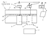
- An operator 51 now reads first the actual value 56 for the position of the stapling head 3 directly on the mechanical scale 52, goes to the used as Mahs Wheat 8 display 55 of the machine control 4 and compares the read actual value 56 with a on the display Returned to the stitching slide 7, the operator 51 shifts the stapling head 3 in accordance with the previously read setpoint value 57 until it detects a corresponding desired value 58 on the mechanical scale 52. This sets a nominal position 53 of the stapling head 3. The displacement is shown by a dash-dotted arrow. The farther the display 55 is away from the stapling carriage 7, the greater the distance that the operator 51 has traveled and the more greater are both the time required for it and the possible sources of error.
- a stapling head 3 is shown, which is slidably mounted on a stapling carriage 7.
- a position detection device 5 is shown symbolically, with their components in Fig. 3 are shown in detail.
- the recess 17 may be formed as a receiving device for standardized mechanical scales.
- a fitting aid 8 is also shown symbolically, which in turn comprises a signaling device 9, which in 6 and FIG is shown in detail. According to a specific production order, a plurality of such stitching heads 3 may be slidably mounted side by side on the stitching carriage 7 as needed.
- the signaling device 9 is in turn connected to a machine control 4, wherein this connection is shown only sketched.
- the machine control 4 calculates the desired position 53 of the stapling head 3 from the predetermined position of a staple to be inserted into the printed product to be stapled in a specific production order and outputs the calculated values on the signaling device 9 of the device 8.
- An operator 51 who now has this signaling device 9 and the corresponding stapling head 3 in view, places and moves the stapling head 3 by means of the instructions issued by the signaling device 9 until the position of the stapling head 3 required for the production job is reached and this is achieved the signaling device 9 is displayed accordingly. Similarly, all other stitching heads are placed and moved until the operator 51 has implemented all the instructions of the set-up aid 8.
- each stapling head 3 enables the location data to be read near the location and the corresponding positioning Spot.
- the display 55 of the machine controller 4 is not required in the inventive solution as in the prior art as bamboos silk 8.
- Fig. 3 shows the effective components of the position detection device 5 Fig. 2 having an electronic scale 6.
- this comprises a sensor arrangement 10 with a plurality of measurement electrodes 11 arranged next to one another and arranged on the front side of a printed circuit board 36.
- a driver 32 active shield 35 is arranged ( Fig. 4, Fig. 5 ).
- a position detection of a stapling head 3 is characterized in that the capacitance is measured at each measuring electrode 11, which has this against the corresponding stapling head 3.
- a measuring electronics required for this purpose has a capacitance-determining circuit 31 and a multiplexer 33, as in FIG Fig. 5 illustrated, wherein the multiplexer 33 is connected to the measuring electrodes 11 of the sensor assembly 10.
- each measuring electrode 11 delivers a capacitance value.
- An increase in the capacitance value from one measuring electrode 11 to the next suggests that a stapling head 3 begins there. Since at a certain position of the stapling head 3 not all measuring electrodes 11 are completely covered, an interpolation of the measured values is carried out in order to determine the exact position of each stapling head 3.
- Fig. 6 and Fig. 7 show two variants of one connected to the machine control device 4 LLCs Love 8, which is arranged either directly on the stapling head 3 or in the region of the stapling head 3.
- Variously configured signaling devices 9 of this device aid 8 have either a numerical display 14 (FIG. Fig. 6 ) or a display with analogue symbols ( Fig. 7 ) on.
- the numeric display 14 off Fig. 6 can indicate the actual and / or desired position of the corresponding stapling head 3.
- An operator 51 can use these values to quickly and easily place each stapling head 3 in the desired position.
- all further stitching heads 3 are displaced by means of each individual signal device 9.
- the bamboos silk 8 off Fig. 7 with the analog symbols has two opposite direction indicators 12, for example "left” and “right”, and an end point display 13.
- one of the direction indicators 12 lights up and when the desired position 53 of the stapling head 3 is reached, the end point indicator 13 lights up. This indicates to the operator 51 whether to move the corresponding stapling head 3 to the left or to the right in the position calculated by the machine control 4 according to the production order.
- a stapler is arranged on the stapling carriage 7 for each stapling head 3.
- the positioning of the clincher can take place analogously to the positioning of the stapling head 3.
- the Umbieger can also be placed on the basis of the position of the stitching heads 3.
Landscapes
- Engineering & Computer Science (AREA)
- Textile Engineering (AREA)
- Folding Of Thin Sheet-Like Materials, Special Discharging Devices, And Others (AREA)
- Dovetailed Work, And Nailing Machines And Stapling Machines For Wood (AREA)
Abstract
Description
- Die vorliegende Erfindung betrifft eine Vorrichtung und ein Verfahren zum Heften von Druckprodukten mit mindestens einem auf einem Heftschlitten verschiebbar angebrachten Heftkopf und mit pro Heftkopf mindestens einer an einer Maschinensteuerung der Vorrichtung angeschlossenen und mit dem mindestens einen Heftkopf zusammenwirkende Positionserkennungseinrichtung für die Erfassung der Ist-Position des mindestens einen Heftkopfs und mit mindestens einer Einrichtungshilfe zur Positionierung des mindestens einen Heftkopfs in einer Soll-Position.
- In der Druckweiterverarbeitung werden Druckprodukte vielfach mit Klammern geheftet, wobei zu diesem Zweck eine Drahtheftvorrichtung verwendet wird. Drahtheftvorrichtungen weisen jeweils einen Heftkopf und einen Umbieger auf, mit denen der Heftvorgang durchgeführt wird. Zum Heftvorgang gehört das Zuführen eines Drahtes, das Abschneiden eines Rohlings, die Klammerformung, das Durchstechen des zu heftenden Druckproduktes mit der Klammer und das Umbiegen der beiden Klammerschenkel.
- Ein Heftschlitten mit mindestens einem Heftkopf ist in einem Abschnitt der Heftvorrichtung, die beispielsweise als Sammelhefter ausgebildet ist, beweglich angebracht und heftet die Druckbogen der zu heftenden Druckprodukte zusammen, während die Heftvorrichtung weiterläuft, das heisst der Heftschlitten bewegt sich während der Heftung synchron mit den zu heftenden Druckprodukten. Somit wird die Transportbewegung nicht gestoppt, sondern die Druckprodukte werden in Bewegung geheftet.
- In Abhängigkeit vom Format der Druckprodukte sind unterschiedlich viele Heftklammern an unterschiedlichen Stellen anzubringen. Zum Heften von Druckprodukten mit unterscheidenden Formaten muss die verwendete Heftvorrichtung auf das Format des jeweils zu heftenden Druckproduktes eingestellt werden, was zu relativ langen Stillstandzeiten der Heftvorrichtung führt, oder es muss für jedes Format des Druckprodukts eine im Hinblick auf das entsprechende Format eingestellte Heftvorrichtung bereitgehalten werden, was zu hohen Kosten führt.
- Es sind im Stand der Technik Verfahren und Vorrichtungen bekannt, mit denen Heftköpfe vom Service-Personal entsprechend den Vorgaben einer Maschinensteuerung mit Hilfe eines Massstabs positioniert werden. Bei dem Sammelhefter "Primera" von Müller Martini wird beispielsweise auf Grund eines Fertigungsauftrags eine Anzahl von Heftklammern und deren Position vorgegeben. Die Maschinensteuerung der Heftvorrichtung errechnet aus der im Fertigungsauftrag definierten Position der Heftklammern die Anzahl und die Position der Heftköpfe auf einem Heftschlitten und gibt die errechneten Werte auf einem zentralen Display aus. Ein Maschinenführer platziert nun mit Hilfe der vom Display der Maschinensteuerung abgelesenen Werte die Heftköpfe der Heftvorrichtung auf dem Heftschlitten, der zu diesem Zweck einen solchen Massstab aufweist. Dieser Einrichtungsvorgang birgt die Gefahr, dass entweder beim Ablesen oder beim Übertragen der Werte Fehler auftreten, was zu fehlerhaft gehefteten Druckprodukten führen kann.
- Aus der
EP916515 A1 - Aus der
DE10354362 A1 ist eine Heftvorrichtung zum Heften von Druckprodukten mit wenigstens zwei auf einer Heftkopfeinheit befestigten Heftköpfen bekannt, bei welcher der Abstand der Heftköpfe zueinander durch eine Antriebseinheit einstellbar ist. Je nach Art und Grösse der zu heftenden Druckprodukte kann hier ein unterschiedlicher Abstand der Heftköpfe zueinander motorisch eingestellt werden. Diese Umrüstung einer solchen Sammelheftmaschine kann zwar schneller erfolgen, doch hier liegen andere Fehlerquellen vor, da keine direkte Kontrolle der Position der Heftköpfe beim Einrichten vorgesehen ist. Diese Lösung ermöglicht auch eine gemeinsame Positionierung von Heftkopf und Umbieger durch deren Anordnung auf einem gemeinsam verschiebbaren Heftschlitten. - Der Erfindung liegt die Aufgabe zugrunde, bei einer Vorrichtung und einem Verfahren der eingangs genannten Art Mittel vorzuschlagen, welche eine einfache, schnell durchzuführende und genaue Positionierung von Heftköpfen einer Heftvorrichtung ermöglichen. Dadurch soll die Einrichtungszeit optimiert und auf ein Minimum reduziert werden.
- Diese Aufgabe wird durch eine Vorrichtung nach dem Oberbegriff des Anspruchs 1 und ein Verfahren nach dem Oberbegriff des Anspruchs 7 durch deren kennzeichnende Merkmale gelöst. Dabei ist die Positionserkennungseinrichtung als elektronischer Massstab ausgebildet, wobei die Einrichtungshilfe am Heftkopf oder im Bereich des Heftkopfes angeordnet ist. Die Einrichtungshilfe weist eine Signaleinrichtung auf, mit der eine Verstellrichtung und/oder ein Verstellwert zum Verstellen des mindestens einen Heftkopfes in die Soll-Position anzeigbar ist, wobei der mindestens eine Heftkopf auf dem Heftschlitten entsprechend der angezeigten Verstellrichtung und/oder dem Verstellwert in die Soll-Position verschiebbar ist.
- Durch die in den Unteransprüchen genannten Massnahmen sind vorteilhafte Ausführungen und Weiterbildungen der Erfindung möglich. In einer bevorzugten Ausführungsform ist der elektronische Massstab für die Durchführung einer kapazitiven Messung ausgebildet. Vorteilhaft sind die kleinen Abmessungen solcher kapazitiver Messvorrichtungen. In einer weiteren Ausführungsform umfasst der elektronische Massstab eine Sensoranordnung mit mehreren Messelektroden. Dadurch kann beispielsweise eine gleichzeitige und daher schnellere Positionserfassung mehrerer Heftköpfe erfolgen. Weil der Heftkopf während seiner Positionierung gegenüber der Sensoranordnung verschiebbar ist, kann eine permanente Ortung dieses Heftkopfes erfolgen.
- Wenn in einer bevorzugten Ausführungsform die Signaleinrichtung eine Richtungsanzeige und/oder eine Endpunktanzeige aufweist, erleichtert dies die genaue Positionierung der Heftköpfe. Eine noch genauere Positionierung wird in einer weiteren Ausführungsform ermöglicht, bei der die Signaleinrichtung eine numerische Anzeige zum Ausgeben eines Wertes kleiner oder grösser als Null vor dem Erreichen der Soll-Position des Heftkopfs und eines Wertes gleich Null beim Erreichen der Soll-Position des Heftkopfs aufweist.
- Mit dem erfindungsgemässen Verfahren erfolgt eine Positionsanpassung mindestens eines Heftkopfs auf einem Heftschlitten gemäss einem Fertigungsauftrag. Dafür wird am mindestens einen Heftkopf oder im Bereich des mindestens einen Heftkopfs eine Verstellrichtung oder einen Verstellwert für die Verstellung des mindestens einen Heftkopfes in die Soll-Position angezeigt. Darauf hin wird der mindestens eine Heftkopf entsprechend der angezeigten Verstellrichtung und/oder des Verstellwerts durch den Bediener in die Soll-Position verschoben.
- In einer Ausführungsform des erfinderischen Verfahrens wird die Erkennung der Ist-Position des mindestens einen Heftkopfs kapazitiv durchgeführt. Zur Erkennung der Ist-Position des mindestens einen Heftkopfs wird vorteilhaft eine Sensoranordnung mit mehreren Messelektroden verwendet.
- Bei einer Weiterbildung des Verfahrens wird an jeder Messelektrode die Kapazität gegen den Heftkopf gemessen, wobei durch eine mathematische Auswertung, insbesondere eine Interpolation, der einzelnen Messwerte die Ist-Position des mindestens einen Heftkopfs ermittelt wird. Dabei erfolgt vorteilhaft vor dem Erreichen der Soll-Position des Heftkopfs eine Richtungsanzeige und beim Erreichen der Soll-Position des Heftkopfs eine Endpunktanzeige. Diese Art der Anzeige erleichtert die Einrichtung eines Heftkopfs in eine gewünschte Position. In einer weiteren Ausführungsform wird auf einer optischen Signaleinrichtung vor dem Erreichen der Soll-Position des Heftkopfs ein Wert kleiner oder grösser Null und beim Erreichen der Soll-Position des Heftkopfs ein Wert gleich Null numerisch angezeigt. Zum Einstellen des Heftkopfs auf dem Heftschlitten kann hier vorteilhaft ein numerischer Wert verwendet werden.
- Vorteilhaft wird eine Heftstation zum Heften von Druckprodukten mit mindestens einer erfindungsgemässen Vorrichtung oder ein Sammelhefter mit mindestens einer solchen Heftstation ausgestattet.
- Nachstehend wird die Erfindung unter Bezugnahme auf die Zeichnung, auf die hinsichtlich aller erfindungswesentlichen und in der Beschreibung nicht näher herausgestellten Einzelheiten ausdrücklich Bezug genommen wird, erläutert. Alle für das unmittelbare Verständnis der Erfindung nicht wesentlichen Elemente sind weggelassen worden. Gleiche Elemente sind in den einzelnen Figuren mit den gleichen Bezugszeichen versehen. Es zeigt:
- Fig. 1
- eine schematische Darstellung einer Seitenansicht auf einen Bereich einer Vorrichtung zum Heften von Druckprodukten mit einer Positionierung nach dem Stand der Technik,
- Fig. 2
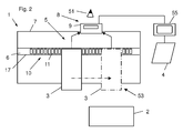
- eine schematische Darstellung einer Seitenansicht der erfindungsgemässen Vorrichtung zum Heften von Druckprodukten mit einer Positionserkennungseinrichtung und einer Einrichtungshilfe,
- Fig. 3
- Komponenten der Positionserkennungseinrichtung,
- Fig. 4
- eine Darstellung des Messverfahrens,
- Fig. 5
- eine Wirkungsdarstellung der Positionserkennung eines Heftkopfes,
- Fig. 6
- eine analoge Anzeige der Einrichtungshilfe und
- Fig. 7
- eine digitale Anzeige der Einrichtungshilfe.
- In dem in
Fig. 1 gezeigten Bereich einer Vorrichtung 1 gemäss dem Stand der Technik zum Heften von Druckprodukten 2 ist ein Heftkopf 3 dargestellt, der auf einem Heftschlitten 7 verschiebbar angebracht ist. In einer als Aussparung 17 ausgebildeten Aufnahmevorrichtung des Heftschlittens 7 ist eine als mechanischer Massstab 52 ausgebildete Positionserkennungseinrichtung 5 angeordnet. Entsprechend einem bestimmten Fertigungsauftrag, können mehrere solcher Heftköpfe 3 je nach Bedarf nebeneinander auf dem Heftschlitten 7 verschiebbar angeordnet sein. Eine erste Position des Heftkopfs 3 ist durch einen abgelesenen Ist-Wert 56 gekennzeichnet. Eine zweite Position des Heftkopfs 3 ist durch einen vorgegebenen Soll-Wert 57 gekennzeichnet. Dieser vorgegebene Soll-Wert 57 wird entsprechend einem Fertigungsauftrag auf einem Display 55 einer Maschinensteuerung 4 dargestellt. - Ein Bediener 51 liest nun zuerst den Ist-Wert 56 für die Position des Heftkopfs 3 direkt am mechanischen Massstab 52 ab, begibt sich zu dem als Einrichtungshilfe 8 genutzten Display 55 der Maschinensteuerung 4 und vergleicht den abgelesenen Ist-Wert 56 mit einem auf dem Display 55 der Maschinensteuerung 4 vorgegebenen Soll-Wert 57. Zum Heftschlitten 7 zurückgekehrt verschiebt der Bediener 51 den Heftkopf 3 entsprechend dem zuvor abgelesenen Soll-Wert 57 so lange bis er einen entsprechenden Soll-Wert 58 auf dem mechanischen Massstab 52 erkennt. Damit ist eine Soll-Position 53 des Heftkopfs 3 eingestellt. Der Verschiebeweg ist mittels eines strichpunktierten Pfeils dargestellt. Je weiter das Display 55 vom Heftschlitten 7 entfernt ist, desto grösser ist der Weg, den der Bediener 51 zurückgelegt hat und desto grösser sind sowohl die dafür erforderliche Zeitdauer als auch die mögliche Fehlerquellen.
- In der in
Fig. 2 gezeigten erfindungsgemässen Vorrichtung 1 zum Heften von Druckprodukten 2 ist ein Heftkopf 3 dargestellt, der auf einem Heftschlitten 7 verschiebbar angebracht ist. In einer ebenfalls als Aussparung 17 ausgebildeten Aufnahmevorrichtung des Heftschlittens 7, ist hier eine Positionserkennungseinrichtung 5 symbolisch dargestellt, wobei ihre Komponenten inFig. 3 detailliert gezeigt sind. Die Aussparung 17 kann als Aufnahmevorrichtung für standardisierte mechanische Massstäbe ausgebildet sein. Im Bereich des Heftkopfes 3 ist eine Einrichtungshilfe 8 ebenfalls symbolisch dargestellt, die ihrerseits eine Signaleinrichtung 9 umfasst, die inFig. 6 und Fig.7 detailliert dargestellt ist. Entsprechend einem bestimmten Fertigungsauftrag, können mehrere solcher Heftköpfe 3 je nach Bedarf, nebeneinander auf dem Heftschlitten 7 verschiebbar angebracht sein. Die Signaleinrichtung 9 ist ihrerseits mit einer Maschinensteuerung 4 verbunden, wobei diese Verbindung nur skizziert dargestellt ist. - Die Maschinensteuerung 4 errechnet aus der in einem bestimmten Fertigungsauftrag vorgegebenen Position einer in das zu heftende Druckprodukt einzubringende Heftklammer die Soll-Position 53 des Heftkopfes 3 und gibt die errechneten Werte auf der Signaleinrichtung 9 der Einrichtungshilfe 8 aus. Ein Bediener 51, der nunmehr diese Signaleinrichtung 9 und den entsprechenden Heftkopf 3 gleichzeitig im Blickfeld hat, platziert und verschiebt den Heftkopf 3 mit Hilfe der von der Signaleinrichtung 9 ausgegebenen Anweisungen, bis die für den Fertigungsauftrag erforderliche Position des Heftkopfes 3 erreicht ist und dies auf der Signaleinrichtung 9 entsprechend angezeigt wird. Analog werden alle weiteren Heftköpfe platziert und verschoben, bis der Bediener 51 sämtliche Anweisungen der Einrichtungshilfe 8 umgesetzt hat.
- Dieser Einrichtungsvorgang vermeidet Fehler beim Ablesen oder beim Übertragen der Werte wie sie bei Vorrichtungen nach dem Stand der Technik vorkommen. Erfindungsgemäss ermöglicht die jeweilige Signaleinrichtung 9 eines jeden Heftkopfs 3 das ortsnahe Ablesen der Positionsdaten und die entsprechende Positionierung an Ort und Stelle. Das Display 55 der Maschinensteuerung 4 wird bei der erfindungsgemässen Lösung nicht wie im Stand der Technik als Einrichtungshilfe 8 benötigt.
-
Fig. 3 zeigt die wirksamen Komponenten der Positionserkennungseinrichtung 5 ausFig. 2 , die einen elektronischen Massstab 6 aufweist. Dieser umfasst in vorliegendem Ausführungsbeispiel eine Sensoranordnung 10 mit mehreren nebeneinander angeordneten Messelektroden 11, die auf der Vorderseite einer Leiterplatte 36 angeordnet sind. Auf der Rückseite der Leiterplatte 36 ist eine mit einem Treiber 32 versehene aktive Abschirmung 35 angeordnet (Fig. 4, Fig. 5 ). - Wie in
Fig. 5 dargestellt, erfolgt eine Positionserkennung eines Heftkopfes 3 dadurch, dass an jeder Messelektrode 11 die Kapazität gemessen wird, welche diese gegen den entsprechenden Heftkopf 3 aufweist. Voraussetzung dafür ist die elektrische Verbindung des Heftkopfs 3 an die Masse 15, wie in einer skizzierten Darstellung des Messverfahrens ausFig. 4 gezeigt. - Durch Interpolation der einzelnen Messwerte wird die genaue Position jedes einzelnen Heftkopfs 3 bestimmt. Eine dafür erforderliche Messelektronik weist einen Schaltkreis 31 zur Bestimmung der Kapazität und einen Multiplexer 33 auf, wie in
Fig. 5 dargestellt, wobei der Multiplexer 33 mit den Messelektroden 11 der Sensoranordnung 10 verbunden ist. Für die Auswertung der Messergebnisse liefert jede Messelektrode 11 einen Kapazitätswert. Eine Erhöhung des Kapazitätswerts von einer Messelektrode 11 zur nächsten lasst darauf schliessen, dass dort ein Heftkopf 3 beginnt. Da bei einer bestimmten Position des Heftkopfs 3 nicht alle Messelektroden 11 vollständig überdeckt werden, wird eine Interpolation der Messwerte ausgeführt, um die genaue Position eines jeden Heftkopfes 3 zu bestimmen. -
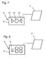
Fig. 6 und Fig. 7 zeigen zwei Varianten einer mit der Maschinensteuerung 4 verbundenen Einrichtungshilfe 8, die entweder direkt am Heftkopf 3 oder im Bereich des Heftkopfs 3 angeordnet ist. Verschieden ausgebildete Signaleinrichtungen 9 dieser Einrichtungshilfe 8 weisen entweder eine numerische Anzeige 14 (Fig. 6 ) oder eine Anzeige mit analogen Symbolen (Fig. 7 ) auf. - Die numerische Anzeige 14 aus
Fig. 6 kann die Ist- und/oder Soll-Position des entsprechenden Heftkopfes 3 anzeigen. Ein Bediener 51 kann anhand dieser Werte jeden Heftkopf 3 schnell und einfach in die gewünschte Position platzieren. Analog werden anhand jeder einzelnen Signaleinrichtung 9 alle weiteren Heftköpfe 3 verschoben. - Die Einrichtungshilfe 8 aus
Fig. 7 mit den analogen Symbolen weist zwei entgegengesetzte Richtungsanzeigen 12, beispielsweise "nach links" und "nach rechts", und eine Endpunktanzeige 13 auf. Vor dem Erreichen der Soll-Position 53 des Heftkopfs 3 leuchtet eine der Richtungsanzeigen 12 und beim Erreichen der Soll-Position 53 des Heftkopfs 3 leuchtet die Endpunktanzeige 13 auf. Dies zeigt dem Bediener 51 an, ob er den entsprechenden Heftkopf 3 nach links oder nach rechts in die von der Maschinensteuerung 4 dem Fertigungsauftrag entsprechend berechnete Position bewegen soll. - Bei dem gezeigten Ausführungsbeispiel ist am Heftschlitten 7 für jeden Heftkopf 3 auch ein nicht dargestellter Umbieger angeordnet. Bei Ausführungsformen, bei denen der Heftkopf 3 und der dazugehörige Umbieger auf je einem Heftschlitten 7 bzw. einem Umbiegerschlitten angeordnet sind, kann die Positionierung des Umbiegers analog zum Positionieren des Heftkopfes 3 erfolgen. Alternativ können die Umbieger auch anhand der Position der Heftköpfe 3 platziert werden.
Claims (14)
- Vorrichtung (1) zum Heften von Druckprodukten (2) mit mindestens einem auf einem Heftschlitten (7) verschiebbar angebrachten Heftkopf (3) und mit pro Heftkopf (3) mindestens einer an einer Maschinensteuerung (4) der Vorrichtung (1) angeschlossenen und mit dem mindestens einen Heftkopf (3) zusammenwirkende Positionserkennungseinrichtung (5) für die Erfassung der Ist-Position des mindestens einen Heftkopfs (3) und mit mindestens einer Einrichtungshilfe (8) zur Positionierung des mindestens einen Heftkopfs (3) in einer Soll-Position (53),
dadurch gekennzeichnet, dass
die Positionserkennungseinrichtung (5) als elektronischer Massstab (6) ausgebildet und die Einrichtungshilfe (8) am Heftkopf (3) oder im Bereich des Heftkopf (3) angeordnet ist und dass die Einrichtungshilfe (8) eine Signaleinrichtung (9) aufweist, mit der eine Verstellrichtung und/oder ein Verstellwert zum Verstellen des mindestens einen Heftkopfes (3) in die Soll-Position (53) anzeigbar ist und wobei der mindestens eine Heftkopf (3) auf dem Heftschlitten (7) entsprechend der angezeigten Verstellrichtung und/oder dem Verstellwert in die Soll-Position (53) verschiebbar ist. - Vorrichtung (1) nach Anspruch 1, dadurch gekennzeichnet, dass, der elektronische Massstab (6) zur Durchführung einer kapazitiven Messung ausgebildet ist.
- Vorrichtung (1) nach Anspruch 1 oder 2 , dadurch gekennzeichnet, dass der elektronische Massstab (6) eine Sensoranordnung (10) mit mehreren Messelektroden (11) umfasst.
- Vorrichtung (1) nach Anspruch 3, dadurch gekennzeichnet, dass der Heftkopf (3) während seiner Positionierung gegenüber der Sensoranordnung (10) verschiebbar ist.
- Vorrichtung (1) nach einem der Ansprüche 1 bis 4, dadurch gekennzeichnet, dass, die Signaleinrichtung (9) eine Richtungsanzeige (12) und/oder eine Endpunktanzeige (13) aufweist.
- Vorrichtung (1) nach einem der Ansprüche 1 bis 5, dadurch gekennzeichnet, dass, die Signaleinrichtung (9) eine numerische Anzeige (14) zum Ausgeben eines Wertes kleiner oder grösser als Null vor dem Erreichen der Soll-Position (53) des Heftkopfs (3) und eines Wertes gleich Null beim Erreichen der Soll-Position (53) des Heftkopfs (3) aufweist.
- Verfahren zum Heften von Druckprodukten (2) mit mindestens einem auf einem Heftschlitten (7) verschiebbar angebrachten Heftkopf (3) zur Anpassung an einen neuen Fertigungsauftrag bei dem eine Ist-Position des mindestens einen Heftkopf (3) erkannt wird, von einer Maschinensteuerung (4) eine Soll-Position (53) des mindestens einen Heftkopf (3) für den neuen Fertigungsauftrag ermittelt wird und der Heftkopf (3) auf dem Heftschlitten (7) in die Soll-Position (53) verschoben wird, dadurch gekennzeichnet, dass am mindestens einen Heftkopf (3) oder im Bereich des mindestens einen Heftkopfs (3) eine Verstellrichtung oder einen Verstellwert für die Verstellung des mindestens einen Heftkopfes (3) in die Soll-Position (53) angezeigt und der mindestens eine Heftkopf (3) entsprechend der Verstellrichtung und/oder des Verstellwerts in die Soll-Position (53) verschoben wird.
- Verfahren nach Anspruch 7, dadurch gekennzeichnet, dass, die Erkennung der Ist-Position des mindestens einen Heftkopf (3) kapazitiv durchgeführt wird.
- Verfahren nach Anspruch 8, dadurch gekennzeichnet, dass zur Erkennung der Ist-Position des mindestens einen Heftkopfs (3) eine Sensoranordnung (10) mit mehreren Messelektroden (11) verwendet wird.
- Verfahren nach Anspruch 9, dadurch gekennzeichnet, dass an jeder Messelektrode (11) die Kapazität gegen den Heftkopf (3) gemessen wird, wobei durch eine mathematische Auswertung, insbesondere eine Interpolation, der einzelnen Messwerte die Ist-Position des mindestens einen Heftkopfs (3) ermittelt wird.
- Verfahren nach einem der vorherigen Ansprüche, dadurch gekennzeichnet, dass, vor dem Erreichen der Soll-Position (53) des Heftkopfs (3) eine Richtungsanzeige (12) und beim Erreichen der Soll-Position (53) des Heftkopfs (3) eine Endpunktanzeige (13) erfolgt.
- Verfahren nach einem der Ansprüche 7 bis 11, dadurch gekennzeichnet, dass, vor dem Erreichen der Soll-Position (53) des Heftkopfs (3) ein Wert kleiner oder grösser Null und beim Erreichen der Soll-Position (53) des Heftkopfs (3) ein Wert gleich Null auf einer optischen Signaleinrichtung (9) numerisch angezeigt wird.
- Heftstation zum Heften von Druckprodukten (2) mit mindestens einer Vorrichtung nach einem der Ansprüche 1 bis 6.
- Sammelhefter mit mindestens einer Heftstation nach Anspruch 13.
Applications Claiming Priority (1)
| Application Number | Priority Date | Filing Date | Title |
|---|---|---|---|
| CH5522013 | 2013-03-06 |
Publications (2)
| Publication Number | Publication Date |
|---|---|
| EP2774773A1 true EP2774773A1 (de) | 2014-09-10 |
| EP2774773B1 EP2774773B1 (de) | 2016-06-29 |
Family
ID=47845662
Family Applications (1)
| Application Number | Title | Priority Date | Filing Date |
|---|---|---|---|
| EP14157425.1A Not-in-force EP2774773B1 (de) | 2013-03-06 | 2014-03-03 | Vorrichtung und Verfahren zum Heften von Druckprodukten |
Country Status (1)
| Country | Link |
|---|---|
| EP (1) | EP2774773B1 (de) |
Citations (2)
| Publication number | Priority date | Publication date | Assignee | Title |
|---|---|---|---|---|
| EP0916515A1 (de) | 1997-11-12 | 1999-05-19 | Brehmer Buchbindereimaschinen GmbH | Maschinen zum Heften von Bogenmaterial |
| EP1422074A1 (de) * | 2002-11-22 | 2004-05-26 | Hohner Maschinenbau GmbH | Heftvorrichtung, Sammelheftmaschine mit dieser Heftvorrichtung und Verfahren zum Heften unter Verwendung dieser Heftvorrichtung oder dieser Sammelheftmaschine |
-
2014
- 2014-03-03 EP EP14157425.1A patent/EP2774773B1/de not_active Not-in-force
Patent Citations (3)
| Publication number | Priority date | Publication date | Assignee | Title |
|---|---|---|---|---|
| EP0916515A1 (de) | 1997-11-12 | 1999-05-19 | Brehmer Buchbindereimaschinen GmbH | Maschinen zum Heften von Bogenmaterial |
| EP1422074A1 (de) * | 2002-11-22 | 2004-05-26 | Hohner Maschinenbau GmbH | Heftvorrichtung, Sammelheftmaschine mit dieser Heftvorrichtung und Verfahren zum Heften unter Verwendung dieser Heftvorrichtung oder dieser Sammelheftmaschine |
| DE10354362A1 (de) | 2002-11-22 | 2004-06-03 | Hohner Maschinenbau Gmbh | Heftvorrichtung |
Also Published As
| Publication number | Publication date |
|---|---|
| EP2774773B1 (de) | 2016-06-29 |
Similar Documents
| Publication | Publication Date | Title |
|---|---|---|
| DE3136701C1 (de) | Vorrichtung zum Abtasten von auf Druckgut aufgedruckten,die Lagegenauigkeit des Druckfarbenauftrages charakterisierender Passmarken | |
| DE3707866C2 (de) | Vorrichtung zur Registersteuerung einer bahnverarbeitenden Druckmaschine | |
| EP3041661B1 (de) | Vorrichtung zum ausrichten von komponenten einer rundläufermaschine | |
| DE102011006929A1 (de) | Verfahren und Vorrichtung zum Bedrucken wenigstens eines Druckstoffes | |
| EP1882566A2 (de) | Bogenstanz- und -prägemaschine mit Passerausrichtung und Verfahren zum Betreiben einer Bogenstanz- und -prägemaschine | |
| EP2832546A1 (de) | Druckmaschine mit Druckkopfsteuerung | |
| EP2960067B1 (de) | Verfahren zur optimierung der dickeneinstellung eines klebebinders | |
| DE102007043103A1 (de) | Kalibrierung von Farbmessgeräten in einer Druckmaschine | |
| EP2228232A1 (de) | Verfahren zur Kontrolle von Buchblocks, Umschlägen und dergleichen bei der Herstellung von Druckerzeugnissen | |
| EP2465697B1 (de) | Verfahren und Vorrichtung zur Herstellung von klebegebundenen, aus einem Buchblock und einem Umschlag gebildeten Druckerzeugnissen | |
| DE102010009961A1 (de) | Inlinefarbregelung in Druckmaschinen | |
| EP2361785A1 (de) | Verfahren zum Heften von Druckprodukten mit einer Heftmaschine und Heftmaschine zum Durchführen des Verfahrens | |
| EP1457334B1 (de) | Vorrichtung und Verfahren zur Registersteuerung in einer Druckmaschine | |
| EP2774773B1 (de) | Vorrichtung und Verfahren zum Heften von Druckprodukten | |
| DE10350405A1 (de) | Falzhilfsmarke und Verfahren zur Ermittlung der Falzqualität an Falzprodukten | |
| DE4306677C2 (de) | Vorrichtung zur Druckvorbereitung mit einer Druckform einer Druckmaschine | |
| EP0916515B1 (de) | Maschinen zum Heften von Bogenmaterial | |
| EP3169492B1 (de) | Erweiterte druckmarkenfunktion beim digitaldruck | |
| DE102007021787A1 (de) | Verfahren zur Steuerung einer Druckmaschine | |
| DE1423628B2 (de) | Standortanzeigevorrichtung | |
| DE2812453C2 (de) | Einrichtung zur Steuerung und zur Voreinstellung des Registers und zur Ausscheidung der Makulatur an Rotationsmehrfarbendruckmaschinen | |
| EP4434927B1 (de) | Verfahren zum überwachen eines falzvorgangs in einer taschenfalzmaschine | |
| DE4221482C2 (de) | Verfahren zur Lagekontrolle eines Druckbildes auf einer Druckform | |
| EP2106910A1 (de) | Verfahren zur Positionierung einer Druckplatte auf einem Plattenzylinder einer Druckmaschine | |
| DE10203048C2 (de) | Verfahren und Vorrichtung zum Zuordnen von Registerabweichungen bei einer Druckmaschine |
Legal Events
| Date | Code | Title | Description |
|---|---|---|---|
| PUAI | Public reference made under article 153(3) epc to a published international application that has entered the european phase |
Free format text: ORIGINAL CODE: 0009012 |
|
| 17P | Request for examination filed |
Effective date: 20140303 |
|
| AK | Designated contracting states |
Kind code of ref document: A1 Designated state(s): AL AT BE BG CH CY CZ DE DK EE ES FI FR GB GR HR HU IE IS IT LI LT LU LV MC MK MT NL NO PL PT RO RS SE SI SK SM TR |
|
| AX | Request for extension of the european patent |
Extension state: BA ME |
|
| R17P | Request for examination filed (corrected) |
Effective date: 20150213 |
|
| RBV | Designated contracting states (corrected) |
Designated state(s): AL AT BE BG CH CY CZ DE DK EE ES FI FR GB GR HR HU IE IS IT LI LT LU LV MC MK MT NL NO PL PT RO RS SE SI SK SM TR |
|
| GRAP | Despatch of communication of intention to grant a patent |
Free format text: ORIGINAL CODE: EPIDOSNIGR1 |
|
| RIC1 | Information provided on ipc code assigned before grant |
Ipc: B42B 4/00 20060101AFI20150811BHEP |
|
| INTG | Intention to grant announced |
Effective date: 20150901 |
|
| GRAS | Grant fee paid |
Free format text: ORIGINAL CODE: EPIDOSNIGR3 |
|
| INTG | Intention to grant announced |
Effective date: 20151215 |
|
| GRAA | (expected) grant |
Free format text: ORIGINAL CODE: 0009210 |
|
| AK | Designated contracting states |
Kind code of ref document: B1 Designated state(s): AL AT BE BG CH CY CZ DE DK EE ES FI FR GB GR HR HU IE IS IT LI LT LU LV MC MK MT NL NO PL PT RO RS SE SI SK SM TR |
|
| REG | Reference to a national code |
Ref country code: GB Ref legal event code: FG4D Free format text: NOT ENGLISH |
|
| REG | Reference to a national code |
Ref country code: CH Ref legal event code: EP |
|
| REG | Reference to a national code |
Ref country code: AT Ref legal event code: REF Ref document number: 808773 Country of ref document: AT Kind code of ref document: T Effective date: 20160715 |
|
| REG | Reference to a national code |
Ref country code: IE Ref legal event code: FG4D Free format text: LANGUAGE OF EP DOCUMENT: GERMAN |
|
| REG | Reference to a national code |
Ref country code: DE Ref legal event code: R096 Ref document number: 502014000990 Country of ref document: DE |
|
| REG | Reference to a national code |
Ref country code: LT Ref legal event code: MG4D |
|
| PG25 | Lapsed in a contracting state [announced via postgrant information from national office to epo] |
Ref country code: LT Free format text: LAPSE BECAUSE OF FAILURE TO SUBMIT A TRANSLATION OF THE DESCRIPTION OR TO PAY THE FEE WITHIN THE PRESCRIBED TIME-LIMIT Effective date: 20160629 Ref country code: FI Free format text: LAPSE BECAUSE OF FAILURE TO SUBMIT A TRANSLATION OF THE DESCRIPTION OR TO PAY THE FEE WITHIN THE PRESCRIBED TIME-LIMIT Effective date: 20160629 Ref country code: NO Free format text: LAPSE BECAUSE OF FAILURE TO SUBMIT A TRANSLATION OF THE DESCRIPTION OR TO PAY THE FEE WITHIN THE PRESCRIBED TIME-LIMIT Effective date: 20160929 |
|
| REG | Reference to a national code |
Ref country code: NL Ref legal event code: MP Effective date: 20160629 |
|
| PG25 | Lapsed in a contracting state [announced via postgrant information from national office to epo] |
Ref country code: GR Free format text: LAPSE BECAUSE OF FAILURE TO SUBMIT A TRANSLATION OF THE DESCRIPTION OR TO PAY THE FEE WITHIN THE PRESCRIBED TIME-LIMIT Effective date: 20160930 Ref country code: NL Free format text: LAPSE BECAUSE OF FAILURE TO SUBMIT A TRANSLATION OF THE DESCRIPTION OR TO PAY THE FEE WITHIN THE PRESCRIBED TIME-LIMIT Effective date: 20160629 Ref country code: LV Free format text: LAPSE BECAUSE OF FAILURE TO SUBMIT A TRANSLATION OF THE DESCRIPTION OR TO PAY THE FEE WITHIN THE PRESCRIBED TIME-LIMIT Effective date: 20160629 Ref country code: RS Free format text: LAPSE BECAUSE OF FAILURE TO SUBMIT A TRANSLATION OF THE DESCRIPTION OR TO PAY THE FEE WITHIN THE PRESCRIBED TIME-LIMIT Effective date: 20160629 Ref country code: HR Free format text: LAPSE BECAUSE OF FAILURE TO SUBMIT A TRANSLATION OF THE DESCRIPTION OR TO PAY THE FEE WITHIN THE PRESCRIBED TIME-LIMIT Effective date: 20160629 Ref country code: SE Free format text: LAPSE BECAUSE OF FAILURE TO SUBMIT A TRANSLATION OF THE DESCRIPTION OR TO PAY THE FEE WITHIN THE PRESCRIBED TIME-LIMIT Effective date: 20160629 |
|
| PG25 | Lapsed in a contracting state [announced via postgrant information from national office to epo] |
Ref country code: EE Free format text: LAPSE BECAUSE OF FAILURE TO SUBMIT A TRANSLATION OF THE DESCRIPTION OR TO PAY THE FEE WITHIN THE PRESCRIBED TIME-LIMIT Effective date: 20160629 Ref country code: IS Free format text: LAPSE BECAUSE OF FAILURE TO SUBMIT A TRANSLATION OF THE DESCRIPTION OR TO PAY THE FEE WITHIN THE PRESCRIBED TIME-LIMIT Effective date: 20161029 Ref country code: RO Free format text: LAPSE BECAUSE OF FAILURE TO SUBMIT A TRANSLATION OF THE DESCRIPTION OR TO PAY THE FEE WITHIN THE PRESCRIBED TIME-LIMIT Effective date: 20160629 Ref country code: SK Free format text: LAPSE BECAUSE OF FAILURE TO SUBMIT A TRANSLATION OF THE DESCRIPTION OR TO PAY THE FEE WITHIN THE PRESCRIBED TIME-LIMIT Effective date: 20160629 Ref country code: CZ Free format text: LAPSE BECAUSE OF FAILURE TO SUBMIT A TRANSLATION OF THE DESCRIPTION OR TO PAY THE FEE WITHIN THE PRESCRIBED TIME-LIMIT Effective date: 20160629 Ref country code: IT Free format text: LAPSE BECAUSE OF FAILURE TO SUBMIT A TRANSLATION OF THE DESCRIPTION OR TO PAY THE FEE WITHIN THE PRESCRIBED TIME-LIMIT Effective date: 20160629 |
|
| PG25 | Lapsed in a contracting state [announced via postgrant information from national office to epo] |
Ref country code: SM Free format text: LAPSE BECAUSE OF FAILURE TO SUBMIT A TRANSLATION OF THE DESCRIPTION OR TO PAY THE FEE WITHIN THE PRESCRIBED TIME-LIMIT Effective date: 20160629 Ref country code: ES Free format text: LAPSE BECAUSE OF FAILURE TO SUBMIT A TRANSLATION OF THE DESCRIPTION OR TO PAY THE FEE WITHIN THE PRESCRIBED TIME-LIMIT Effective date: 20160629 Ref country code: PL Free format text: LAPSE BECAUSE OF FAILURE TO SUBMIT A TRANSLATION OF THE DESCRIPTION OR TO PAY THE FEE WITHIN THE PRESCRIBED TIME-LIMIT Effective date: 20160629 Ref country code: PT Free format text: LAPSE BECAUSE OF FAILURE TO SUBMIT A TRANSLATION OF THE DESCRIPTION OR TO PAY THE FEE WITHIN THE PRESCRIBED TIME-LIMIT Effective date: 20161031 |
|
| REG | Reference to a national code |
Ref country code: DE Ref legal event code: R097 Ref document number: 502014000990 Country of ref document: DE |
|
| PG25 | Lapsed in a contracting state [announced via postgrant information from national office to epo] |
Ref country code: DK Free format text: LAPSE BECAUSE OF FAILURE TO SUBMIT A TRANSLATION OF THE DESCRIPTION OR TO PAY THE FEE WITHIN THE PRESCRIBED TIME-LIMIT Effective date: 20160629 |
|
| 26N | No opposition filed |
Effective date: 20170330 |
|
| PLBE | No opposition filed within time limit |
Free format text: ORIGINAL CODE: 0009261 |
|
| STAA | Information on the status of an ep patent application or granted ep patent |
Free format text: STATUS: NO OPPOSITION FILED WITHIN TIME LIMIT |
|
| PG25 | Lapsed in a contracting state [announced via postgrant information from national office to epo] |
Ref country code: BG Free format text: LAPSE BECAUSE OF FAILURE TO SUBMIT A TRANSLATION OF THE DESCRIPTION OR TO PAY THE FEE WITHIN THE PRESCRIBED TIME-LIMIT Effective date: 20160929 Ref country code: SI Free format text: LAPSE BECAUSE OF FAILURE TO SUBMIT A TRANSLATION OF THE DESCRIPTION OR TO PAY THE FEE WITHIN THE PRESCRIBED TIME-LIMIT Effective date: 20160629 |
|
| PG25 | Lapsed in a contracting state [announced via postgrant information from national office to epo] |
Ref country code: MC Free format text: LAPSE BECAUSE OF FAILURE TO SUBMIT A TRANSLATION OF THE DESCRIPTION OR TO PAY THE FEE WITHIN THE PRESCRIBED TIME-LIMIT Effective date: 20160629 |
|
| REG | Reference to a national code |
Ref country code: IE Ref legal event code: MM4A |
|
| REG | Reference to a national code |
Ref country code: FR Ref legal event code: ST Effective date: 20171130 |
|
| PG25 | Lapsed in a contracting state [announced via postgrant information from national office to epo] |
Ref country code: FR Free format text: LAPSE BECAUSE OF NON-PAYMENT OF DUE FEES Effective date: 20170331 Ref country code: LU Free format text: LAPSE BECAUSE OF NON-PAYMENT OF DUE FEES Effective date: 20170303 |
|
| PG25 | Lapsed in a contracting state [announced via postgrant information from national office to epo] |
Ref country code: IE Free format text: LAPSE BECAUSE OF NON-PAYMENT OF DUE FEES Effective date: 20170303 |
|
| REG | Reference to a national code |
Ref country code: BE Ref legal event code: MM Effective date: 20170331 |
|
| PG25 | Lapsed in a contracting state [announced via postgrant information from national office to epo] |
Ref country code: BE Free format text: LAPSE BECAUSE OF NON-PAYMENT OF DUE FEES Effective date: 20170331 |
|
| PG25 | Lapsed in a contracting state [announced via postgrant information from national office to epo] |
Ref country code: MT Free format text: LAPSE BECAUSE OF FAILURE TO SUBMIT A TRANSLATION OF THE DESCRIPTION OR TO PAY THE FEE WITHIN THE PRESCRIBED TIME-LIMIT Effective date: 20160629 |
|
| PG25 | Lapsed in a contracting state [announced via postgrant information from national office to epo] |
Ref country code: AL Free format text: LAPSE BECAUSE OF FAILURE TO SUBMIT A TRANSLATION OF THE DESCRIPTION OR TO PAY THE FEE WITHIN THE PRESCRIBED TIME-LIMIT Effective date: 20160629 |
|
| GBPC | Gb: european patent ceased through non-payment of renewal fee |
Effective date: 20180303 |
|
| PG25 | Lapsed in a contracting state [announced via postgrant information from national office to epo] |
Ref country code: GB Free format text: LAPSE BECAUSE OF NON-PAYMENT OF DUE FEES Effective date: 20180303 |
|
| PG25 | Lapsed in a contracting state [announced via postgrant information from national office to epo] |
Ref country code: HU Free format text: LAPSE BECAUSE OF FAILURE TO SUBMIT A TRANSLATION OF THE DESCRIPTION OR TO PAY THE FEE WITHIN THE PRESCRIBED TIME-LIMIT; INVALID AB INITIO Effective date: 20140303 |
|
| PG25 | Lapsed in a contracting state [announced via postgrant information from national office to epo] |
Ref country code: CY Free format text: LAPSE BECAUSE OF NON-PAYMENT OF DUE FEES Effective date: 20160629 |
|
| PG25 | Lapsed in a contracting state [announced via postgrant information from national office to epo] |
Ref country code: MK Free format text: LAPSE BECAUSE OF FAILURE TO SUBMIT A TRANSLATION OF THE DESCRIPTION OR TO PAY THE FEE WITHIN THE PRESCRIBED TIME-LIMIT Effective date: 20160629 |
|
| PG25 | Lapsed in a contracting state [announced via postgrant information from national office to epo] |
Ref country code: TR Free format text: LAPSE BECAUSE OF FAILURE TO SUBMIT A TRANSLATION OF THE DESCRIPTION OR TO PAY THE FEE WITHIN THE PRESCRIBED TIME-LIMIT Effective date: 20160629 |
|
| REG | Reference to a national code |
Ref country code: AT Ref legal event code: MM01 Ref document number: 808773 Country of ref document: AT Kind code of ref document: T Effective date: 20190303 |
|
| PG25 | Lapsed in a contracting state [announced via postgrant information from national office to epo] |
Ref country code: AT Free format text: LAPSE BECAUSE OF NON-PAYMENT OF DUE FEES Effective date: 20190303 |
|
| PGFP | Annual fee paid to national office [announced via postgrant information from national office to epo] |
Ref country code: DE Payment date: 20220328 Year of fee payment: 9 Ref country code: CH Payment date: 20220318 Year of fee payment: 9 |
|
| REG | Reference to a national code |
Ref country code: DE Ref legal event code: R119 Ref document number: 502014000990 Country of ref document: DE |
|
| REG | Reference to a national code |
Ref country code: CH Ref legal event code: PL |
|
| PG25 | Lapsed in a contracting state [announced via postgrant information from national office to epo] |
Ref country code: LI Free format text: LAPSE BECAUSE OF NON-PAYMENT OF DUE FEES Effective date: 20230331 Ref country code: DE Free format text: LAPSE BECAUSE OF NON-PAYMENT OF DUE FEES Effective date: 20231003 Ref country code: CH Free format text: LAPSE BECAUSE OF NON-PAYMENT OF DUE FEES Effective date: 20230331 |