EP2773266B1 - Dispositif pour l'application d'un capteur à un site de mesure, trousse d'un dispositif d'application et d'un capteur et utilisation d'un dispositif d'application pour des mesures optiques de paramètres physiologiques - Google Patents
Dispositif pour l'application d'un capteur à un site de mesure, trousse d'un dispositif d'application et d'un capteur et utilisation d'un dispositif d'application pour des mesures optiques de paramètres physiologiques Download PDFInfo
- Publication number
- EP2773266B1 EP2773266B1 EP12762011.0A EP12762011A EP2773266B1 EP 2773266 B1 EP2773266 B1 EP 2773266B1 EP 12762011 A EP12762011 A EP 12762011A EP 2773266 B1 EP2773266 B1 EP 2773266B1
- Authority
- EP
- European Patent Office
- Prior art keywords
- layer
- sensor
- sensor head
- application
- volume
- Prior art date
- Legal status (The legal status is an assumption and is not a legal conclusion. Google has not performed a legal analysis and makes no representation as to the accuracy of the status listed.)
- Active
Links
- 238000005259 measurement Methods 0.000 title claims description 54
- 230000003287 optical effect Effects 0.000 title claims description 20
- 239000012528 membrane Substances 0.000 claims description 40
- 239000007789 gas Substances 0.000 claims description 25
- 239000000975 dye Substances 0.000 claims description 12
- XLYOFNOQVPJJNP-UHFFFAOYSA-N water Substances O XLYOFNOQVPJJNP-UHFFFAOYSA-N 0.000 claims description 10
- CSCPPACGZOOCGX-UHFFFAOYSA-N Acetone Chemical compound CC(C)=O CSCPPACGZOOCGX-UHFFFAOYSA-N 0.000 claims description 8
- BPYKTIZUTYGOLE-IFADSCNNSA-N Bilirubin Chemical compound N1C(=O)C(C)=C(C=C)\C1=C\C1=C(C)C(CCC(O)=O)=C(CC2=C(C(C)=C(\C=C/3C(=C(C=C)C(=O)N\3)C)N2)CCC(O)=O)N1 BPYKTIZUTYGOLE-IFADSCNNSA-N 0.000 claims description 8
- LFQSCWFLJHTTHZ-UHFFFAOYSA-N Ethanol Chemical compound CCO LFQSCWFLJHTTHZ-UHFFFAOYSA-N 0.000 claims description 8
- 230000005855 radiation Effects 0.000 claims description 7
- 238000007789 sealing Methods 0.000 claims description 7
- 238000010521 absorption reaction Methods 0.000 claims description 5
- 230000003595 spectral effect Effects 0.000 claims description 5
- 102000036675 Myoglobin Human genes 0.000 claims description 4
- 108010062374 Myoglobin Proteins 0.000 claims description 4
- 150000001298 alcohols Chemical class 0.000 claims description 4
- 239000012080 ambient air Substances 0.000 claims description 4
- 230000007613 environmental effect Effects 0.000 claims description 2
- 238000004806 packaging method and process Methods 0.000 claims description 2
- 239000010410 layer Substances 0.000 description 57
- 210000003128 head Anatomy 0.000 description 38
- 239000000853 adhesive Substances 0.000 description 10
- 230000001070 adhesive effect Effects 0.000 description 10
- 239000012530 fluid Substances 0.000 description 10
- 239000012790 adhesive layer Substances 0.000 description 6
- 239000000463 material Substances 0.000 description 5
- 229930040373 Paraformaldehyde Natural products 0.000 description 3
- XECAHXYUAAWDEL-UHFFFAOYSA-N acrylonitrile butadiene styrene Chemical compound C=CC=C.C=CC#N.C=CC1=CC=CC=C1 XECAHXYUAAWDEL-UHFFFAOYSA-N 0.000 description 3
- 229920000122 acrylonitrile butadiene styrene Polymers 0.000 description 3
- 239000004676 acrylonitrile butadiene styrene Substances 0.000 description 3
- 238000001514 detection method Methods 0.000 description 3
- 210000000624 ear auricle Anatomy 0.000 description 3
- 239000004033 plastic Substances 0.000 description 3
- 229920003023 plastic Polymers 0.000 description 3
- 229920006324 polyoxymethylene Polymers 0.000 description 3
- VYPSYNLAJGMNEJ-UHFFFAOYSA-N Silicium dioxide Chemical compound O=[Si]=O VYPSYNLAJGMNEJ-UHFFFAOYSA-N 0.000 description 2
- XUIMIQQOPSSXEZ-UHFFFAOYSA-N Silicon Chemical compound [Si] XUIMIQQOPSSXEZ-UHFFFAOYSA-N 0.000 description 2
- VBRNLOQCBCPPHL-UHFFFAOYSA-N calmagite Chemical compound CC1=CC=C(O)C(N=NC=2C3=CC=CC=C3C(=CC=2O)S(O)(=O)=O)=C1 VBRNLOQCBCPPHL-UHFFFAOYSA-N 0.000 description 2
- ORTQZVOHEJQUHG-UHFFFAOYSA-L copper(II) chloride Chemical compound Cl[Cu]Cl ORTQZVOHEJQUHG-UHFFFAOYSA-L 0.000 description 2
- 238000009792 diffusion process Methods 0.000 description 2
- 229920001971 elastomer Polymers 0.000 description 2
- 239000007850 fluorescent dye Substances 0.000 description 2
- 229920002313 fluoropolymer Polymers 0.000 description 2
- 239000004811 fluoropolymer Substances 0.000 description 2
- 238000001746 injection moulding Methods 0.000 description 2
- 230000000149 penetrating effect Effects 0.000 description 2
- 229920001343 polytetrafluoroethylene Polymers 0.000 description 2
- 239000004810 polytetrafluoroethylene Substances 0.000 description 2
- 239000011148 porous material Substances 0.000 description 2
- 229910052710 silicon Inorganic materials 0.000 description 2
- 239000010703 silicon Substances 0.000 description 2
- OBJOZRVSMLPASY-UHFFFAOYSA-N 8-hydroxypyrene-1,3,6-trisulfonic acid Chemical compound C1=C2C(O)=CC(S(O)(=O)=O)=C(C=C3)C2=C2C3=C(S(O)(=O)=O)C=C(S(O)(=O)=O)C2=C1 OBJOZRVSMLPASY-UHFFFAOYSA-N 0.000 description 1
- 229920000298 Cellophane Polymers 0.000 description 1
- 229910021580 Cobalt(II) chloride Inorganic materials 0.000 description 1
- 229910021592 Copper(II) chloride Inorganic materials 0.000 description 1
- 229920012266 Poly(ether sulfone) PES Polymers 0.000 description 1
- KJTLSVCANCCWHF-UHFFFAOYSA-N Ruthenium Chemical compound [Ru] KJTLSVCANCCWHF-UHFFFAOYSA-N 0.000 description 1
- 229910052581 Si3N4 Inorganic materials 0.000 description 1
- 229910000831 Steel Inorganic materials 0.000 description 1
- RTAQQCXQSZGOHL-UHFFFAOYSA-N Titanium Chemical compound [Ti] RTAQQCXQSZGOHL-UHFFFAOYSA-N 0.000 description 1
- NRTOMJZYCJJWKI-UHFFFAOYSA-N Titanium nitride Chemical compound [Ti]#N NRTOMJZYCJJWKI-UHFFFAOYSA-N 0.000 description 1
- 229920006243 acrylic copolymer Polymers 0.000 description 1
- 239000004411 aluminium Substances 0.000 description 1
- XAGFODPZIPBFFR-UHFFFAOYSA-N aluminium Chemical compound [Al] XAGFODPZIPBFFR-UHFFFAOYSA-N 0.000 description 1
- 229910052782 aluminium Inorganic materials 0.000 description 1
- PNEYBMLMFCGWSK-UHFFFAOYSA-N aluminium oxide Inorganic materials [O-2].[O-2].[O-2].[Al+3].[Al+3] PNEYBMLMFCGWSK-UHFFFAOYSA-N 0.000 description 1
- 239000000919 ceramic Substances 0.000 description 1
- 238000006243 chemical reaction Methods 0.000 description 1
- 238000004140 cleaning Methods 0.000 description 1
- GVPFVAHMJGGAJG-UHFFFAOYSA-L cobalt dichloride Chemical compound [Cl-].[Cl-].[Co+2] GVPFVAHMJGGAJG-UHFFFAOYSA-L 0.000 description 1
- 238000011109 contamination Methods 0.000 description 1
- 210000005069 ears Anatomy 0.000 description 1
- 239000000806 elastomer Substances 0.000 description 1
- 238000010292 electrical insulation Methods 0.000 description 1
- 210000003811 finger Anatomy 0.000 description 1
- 239000002346 layers by function Substances 0.000 description 1
- 210000001331 nose Anatomy 0.000 description 1
- HCIIFBHDBOCSAF-UHFFFAOYSA-N octaethylporphyrin Chemical class N1C(C=C2C(=C(CC)C(C=C3C(=C(CC)C(=C4)N3)CC)=N2)CC)=C(CC)C(CC)=C1C=C1C(CC)=C(CC)C4=N1 HCIIFBHDBOCSAF-UHFFFAOYSA-N 0.000 description 1
- 229910052763 palladium Inorganic materials 0.000 description 1
- 230000003071 parasitic effect Effects 0.000 description 1
- 230000035699 permeability Effects 0.000 description 1
- 239000007793 ph indicator Substances 0.000 description 1
- 229910052697 platinum Inorganic materials 0.000 description 1
- 229920000052 poly(p-xylylene) Polymers 0.000 description 1
- 229920000728 polyester Polymers 0.000 description 1
- 229920000642 polymer Polymers 0.000 description 1
- 239000011116 polymethylpentene Substances 0.000 description 1
- 229920000306 polymethylpentene Polymers 0.000 description 1
- -1 polyoxymethylene Polymers 0.000 description 1
- KXXXUIKPSVVSAW-UHFFFAOYSA-K pyranine Chemical compound [Na+].[Na+].[Na+].C1=C2C(O)=CC(S([O-])(=O)=O)=C(C=C3)C2=C2C3=C(S([O-])(=O)=O)C=C(S([O-])(=O)=O)C2=C1 KXXXUIKPSVVSAW-UHFFFAOYSA-K 0.000 description 1
- 229910052707 ruthenium Inorganic materials 0.000 description 1
- 239000004065 semiconductor Substances 0.000 description 1
- 229920000260 silastic Polymers 0.000 description 1
- 239000000377 silicon dioxide Substances 0.000 description 1
- HQVNEWCFYHHQES-UHFFFAOYSA-N silicon nitride Chemical compound N12[Si]34N5[Si]62N3[Si]51N64 HQVNEWCFYHHQES-UHFFFAOYSA-N 0.000 description 1
- 229920002379 silicone rubber Polymers 0.000 description 1
- 239000002356 single layer Substances 0.000 description 1
- 239000000243 solution Substances 0.000 description 1
- 239000010959 steel Substances 0.000 description 1
- 239000000126 substance Substances 0.000 description 1
- 230000001629 suppression Effects 0.000 description 1
- 239000010936 titanium Substances 0.000 description 1
- 229910052719 titanium Inorganic materials 0.000 description 1
- 210000003371 toe Anatomy 0.000 description 1
Images


Classifications
-
- A—HUMAN NECESSITIES
- A61—MEDICAL OR VETERINARY SCIENCE; HYGIENE
- A61B—DIAGNOSIS; SURGERY; IDENTIFICATION
- A61B5/00—Measuring for diagnostic purposes; Identification of persons
- A61B5/02—Detecting, measuring or recording pulse, heart rate, blood pressure or blood flow; Combined pulse/heart-rate/blood pressure determination; Evaluating a cardiovascular condition not otherwise provided for, e.g. using combinations of techniques provided for in this group with electrocardiography or electroauscultation; Heart catheters for measuring blood pressure
- A61B5/0205—Simultaneously evaluating both cardiovascular conditions and different types of body conditions, e.g. heart and respiratory condition
-
- A—HUMAN NECESSITIES
- A61—MEDICAL OR VETERINARY SCIENCE; HYGIENE
- A61B—DIAGNOSIS; SURGERY; IDENTIFICATION
- A61B5/00—Measuring for diagnostic purposes; Identification of persons
- A61B5/68—Arrangements of detecting, measuring or recording means, e.g. sensors, in relation to patient
- A61B5/6801—Arrangements of detecting, measuring or recording means, e.g. sensors, in relation to patient specially adapted to be attached to or worn on the body surface
- A61B5/683—Means for maintaining contact with the body
- A61B5/6832—Means for maintaining contact with the body using adhesives
- A61B5/6833—Adhesive patches
-
- A—HUMAN NECESSITIES
- A61—MEDICAL OR VETERINARY SCIENCE; HYGIENE
- A61B—DIAGNOSIS; SURGERY; IDENTIFICATION
- A61B5/00—Measuring for diagnostic purposes; Identification of persons
- A61B5/145—Measuring characteristics of blood in vivo, e.g. gas concentration, pH value; Measuring characteristics of body fluids or tissues, e.g. interstitial fluid, cerebral tissue
- A61B5/14546—Measuring characteristics of blood in vivo, e.g. gas concentration, pH value; Measuring characteristics of body fluids or tissues, e.g. interstitial fluid, cerebral tissue for measuring analytes not otherwise provided for, e.g. ions, cytochromes
-
- A—HUMAN NECESSITIES
- A61—MEDICAL OR VETERINARY SCIENCE; HYGIENE
- A61B—DIAGNOSIS; SURGERY; IDENTIFICATION
- A61B5/00—Measuring for diagnostic purposes; Identification of persons
- A61B5/145—Measuring characteristics of blood in vivo, e.g. gas concentration, pH value; Measuring characteristics of body fluids or tissues, e.g. interstitial fluid, cerebral tissue
- A61B5/1455—Measuring characteristics of blood in vivo, e.g. gas concentration, pH value; Measuring characteristics of body fluids or tissues, e.g. interstitial fluid, cerebral tissue using optical sensors, e.g. spectral photometrical oximeters
- A61B5/14551—Measuring characteristics of blood in vivo, e.g. gas concentration, pH value; Measuring characteristics of body fluids or tissues, e.g. interstitial fluid, cerebral tissue using optical sensors, e.g. spectral photometrical oximeters for measuring blood gases
- A61B5/14552—Details of sensors specially adapted therefor
-
- A—HUMAN NECESSITIES
- A61—MEDICAL OR VETERINARY SCIENCE; HYGIENE
- A61B—DIAGNOSIS; SURGERY; IDENTIFICATION
- A61B5/00—Measuring for diagnostic purposes; Identification of persons
- A61B5/145—Measuring characteristics of blood in vivo, e.g. gas concentration, pH value; Measuring characteristics of body fluids or tissues, e.g. interstitial fluid, cerebral tissue
- A61B5/1455—Measuring characteristics of blood in vivo, e.g. gas concentration, pH value; Measuring characteristics of body fluids or tissues, e.g. interstitial fluid, cerebral tissue using optical sensors, e.g. spectral photometrical oximeters
- A61B5/14551—Measuring characteristics of blood in vivo, e.g. gas concentration, pH value; Measuring characteristics of body fluids or tissues, e.g. interstitial fluid, cerebral tissue using optical sensors, e.g. spectral photometrical oximeters for measuring blood gases
- A61B5/14556—Measuring characteristics of blood in vivo, e.g. gas concentration, pH value; Measuring characteristics of body fluids or tissues, e.g. interstitial fluid, cerebral tissue using optical sensors, e.g. spectral photometrical oximeters for measuring blood gases by fluorescence
-
- A—HUMAN NECESSITIES
- A61—MEDICAL OR VETERINARY SCIENCE; HYGIENE
- A61B—DIAGNOSIS; SURGERY; IDENTIFICATION
- A61B5/00—Measuring for diagnostic purposes; Identification of persons
- A61B5/48—Other medical applications
- A61B5/4869—Determining body composition
- A61B5/4875—Hydration status, fluid retention of the body
-
- A—HUMAN NECESSITIES
- A61—MEDICAL OR VETERINARY SCIENCE; HYGIENE
- A61B—DIAGNOSIS; SURGERY; IDENTIFICATION
- A61B5/00—Measuring for diagnostic purposes; Identification of persons
- A61B5/68—Arrangements of detecting, measuring or recording means, e.g. sensors, in relation to patient
- A61B5/6801—Arrangements of detecting, measuring or recording means, e.g. sensors, in relation to patient specially adapted to be attached to or worn on the body surface
- A61B5/683—Means for maintaining contact with the body
- A61B5/6838—Clamps or clips
-
- A—HUMAN NECESSITIES
- A61—MEDICAL OR VETERINARY SCIENCE; HYGIENE
- A61B—DIAGNOSIS; SURGERY; IDENTIFICATION
- A61B2560/00—Constructional details of operational features of apparatus; Accessories for medical measuring apparatus
- A61B2560/02—Operational features
- A61B2560/0266—Operational features for monitoring or limiting apparatus function
- A61B2560/028—Arrangements to prevent overuse, e.g. by counting the number of uses
- A61B2560/0285—Apparatus for single use
-
- A—HUMAN NECESSITIES
- A61—MEDICAL OR VETERINARY SCIENCE; HYGIENE
- A61B—DIAGNOSIS; SURGERY; IDENTIFICATION
- A61B2560/00—Constructional details of operational features of apparatus; Accessories for medical measuring apparatus
- A61B2560/04—Constructional details of apparatus
- A61B2560/0443—Modular apparatus
-
- A—HUMAN NECESSITIES
- A61—MEDICAL OR VETERINARY SCIENCE; HYGIENE
- A61B—DIAGNOSIS; SURGERY; IDENTIFICATION
- A61B5/00—Measuring for diagnostic purposes; Identification of persons
- A61B5/68—Arrangements of detecting, measuring or recording means, e.g. sensors, in relation to patient
- A61B5/6801—Arrangements of detecting, measuring or recording means, e.g. sensors, in relation to patient specially adapted to be attached to or worn on the body surface
- A61B5/6813—Specially adapted to be attached to a specific body part
- A61B5/6814—Head
- A61B5/6815—Ear
- A61B5/6816—Ear lobe
Definitions
- the invention is directed to a device for application of a sensor to a measurement site, a kit of an application device and sensor head and the use of an application device for optical measurements of physiological parameters on or through the skin according to the independent claims.
- EP1040788A1 discloses a sensor film which comprises a luminescent indicator which reacts to a parameter to be determined by changing at least one optical characteristic.
- An applicator tube is applied to a measuring surface. The edge of the applicator tube facing the measuring surface lies elastically against the sensor film and is impermeable to radiation.
- US4003707A discloses an arrangement for measuring the concentration of gases in a sample including the generation of a monochromatic light beam.
- An indicator generates light signals indicative of the concentration of the gases in a sample to be measured and includes a light-transmissive surface positioned to be impinged by the monochromatic light beam, a diffusion membrane adapted to be placed in the proximity of a sample and being permeable to a selected gas component thereof, and an indieating substance positioned to be impinged by the monochromatic light beam penetrating the light-transmissive surface and by the gas component penetrating the diffusion membrane.
- EP0008460A2 discloses an adhesive mounting for measured value pick-ups, comprising an adhesive carrier, which has adhesive surfaces on both sides, for sticking on to the application surface of the pick-up, on the one hand, and for sticking the adhesive carrier to the measuring point, on the other hand.
- US2003214655 A1 discloses a reflectometer for detecting and measuring subtle changes in colour and shade of colour. A protruding nose portion of the reflectometer can be inserted into a respective opening of a transdermal patch.
- the object is accomplished by a device for application of a sensor to a measurement site according to independent claim.
- the device has at least one application area enabling the application of the device to a patient skin. Furthermore, the device comprises an interface for connecting the device to a sensor head, wherein the device comprises at least a wall arrangement providing an applicator volume above the patient's skin.
- the wall arrangement comprises a patient's side and a sensor side. At least one gas permeable membrane separates the applicator volume into a first volume being directed to the measuring site at the patient's side of the wall arrangement and a second volume being separated from the patient's skin and directed to the sensor side of the wall arrangement.
- a device for application of a sensor to a measurement site comprising at least one gas permeable membrane enables measurements of gases diffusing from the measurement site and still separates the sensor head from a direct contact to the measurement site. This leads to a lower contamination of the sensor head used.
- the volume of the first and the second volume each does not exceed 10 mm 3 and is preferably smaller than 4 mm 3 for sensor application areas of approx. 80 mm 2 .
- the application area comprises an adhesive, which is compatible with the human skin.
- the wall arrangement comprises walls that are perpendicular to the measurement site. This way, a volume above the measurement site is created.
- the wall arrangement can be polyangular, circular or elliptical. The largest extension of the wall arrangement does not exceed 5 cm preferably does not exceed 1.5 cm.
- a sensor head being inserted into the device is still rotatable while being inserted or thereafter.
- the wall arrangement comprises a patient's side, which is the area of the wall arrangement directly adjacent to the measurement site and a sensor side being the portion of the wall arrangement directed to the sensor.
- the gas-permeable membrane is arranged substantially in parallel to the measurement site. As a matter of course, the gas permeable membrane can further have other functions or can be combined with additional
- At least the wall arrangement and the membrane cannot be disassembled without being destroyed.
- the interface enables the connection of a sensor head to the device.
- the interface can comprise a sealing function to prevent significant gas leakage and/or to prevent disturbances of optical measurements by ambient light.
- the device does not comprise any electrical or electronical components; as understood herein identification means such as RFID-chips, RFID-antennas, or identification resistors and printable electronical or optical components such as, but not limited to, OFETs, OLEDs(organic light emitting diodes), or OPDs (organic photo diodes) are not electronic or electrical components.
- identification means such as RFID-chips, RFID-antennas, or identification resistors
- printable electronical or optical components such as, but not limited to, OFETs, OLEDs(organic light emitting diodes), or OPDs (organic photo diodes) are not electronic or electrical components.
- the membrane can consist of a polymer, like fluoropolymers, such as PTFE, or Polyester, Polyethylenterephtalat (PET), Polymethylpentene or Parylene or Polyethersulfone (PES), acrylic copolymers, cellophane, rubber or silicon elastomer (silastic) films, or of ceramic or semiconductor or metallic films or thin sheets such as alumina, silica, silicon, silicon nitride, titanium nitride, steels, titanium, aluminium, etc.
- the membrane can be porous or free of pores or contain deliberately introduced pore-like structures, e.g. structured or etched silicon, in particular the membrane can comprise a combination of different porosities such as fine pored and coarse-pored or porous and free of pores.
- the gas-permeable membrane can further be fluid-impermeable.
- the device can also comprise a second fluid-impermeable membrane, additionally to the first, gas-permeable membrane.
- a further fluid-impermeable functionality of the membrane or a second fluid impermeable membrane prevents fluids from getting into the second volume. Hence, no fluid originating from the measurement site can get into direct contact with sensor head, which is important in particular for optical measurements.
- a water trap e.g. a hydrophilic material within the first volume, to intentionally collect the diffusing water from the measurement site.
- the gas-permeable membrane can further be electrically insulating. This leads to a suppression of electrostatic discharge events.
- the application area and/or the wall arrangement on the patient's site is provided with a contact medium (e.g. fluid, gel or paste) as common in sensor application on skin.
- a contact medium e.g. fluid, gel or paste
- the contact medium seals the first volume from ambient air and/or from ambient radiation.
- the contact medium and/or the application layer is covered by a detachable cover layer before use.
- the contact medium and the adhesive layer on the application area can further be the same layer comprising a medium fulfilling both functions.
- a detachable cover layer on the one hand keeps the application layer clean and functional and on the other hand protects the membrane inside the device from external influences during transport or storage.
- Such external influences could be mechanical impacts, fluids, gases, or radiation such as ambient light that influence the membrane or other additional layers being arranged within the device, such that the membrane or the additional layers are destroyed or become non-functional.
- the second volume or the gas-permeable membrane can comprise one or several gas sensitive dyes, wherein preferably the sensitive dyes are arranged in a layer, which preferably is protected by a protection layer against environmental gases before use.
- the sensitive dyes are sensitive to CO 2 (e.g. Calmagite, Naphtol Blue Black, Naphtolphtalein or HPTS (1-hydroxypyren-3,6,8-trisulfonate)), O 2 (e.g. Ruthenium or Pt and Pd octaethylporphyrins based fluorescent dyes), and/or water vapour (e.g. cobalt(II) chloride, copper(II) chloride, calmagite, etc.).
- the sensitive dyes can further comprise a pH-indicating dye or a fluorescent dye.
- a sensitive layer comprising a sensitive dye can be disposed together with the device.
- sensitive dyes only remain stable during a limited time frame. This time frame is significantly shorter than the product life time of a sensor head, especially in case of an optical sensor head.
- the sensitive dye may also be sensitive to atmospheric gases and ambient light
- the sensitive layer is preferably protected by a protection layer before use.
- the sensitive elements of the device may also be protected by gas and light tight packaging of the whole device.
- the interface comprises a sealing element for sealing the second volume from ambient gases and/or ambient radiation in use.
- a further sealing element suppresses the intrusion of ambient air into the second volume. This leads to more accurate measuring results.
- the sealing element can be an elastomer part or some other gastight material.
- the gas-permeable membrane can be an at least partly reflecting layer, having reflecting properties at least in a wavelength range from 400 nm to 1 ⁇ m, a white layer, or a metallic layer.
- an additional at least partly reflecting layer, having reflecting properties at least in a wavelength range from 400 nm to 1 ⁇ m, a white layer, or a metallic layer can be provided.
- the light emitted from the sensor head can be reflected back to a detector within the sensor head and increase the propagation length within the light-affecting element, which can be a gaseous medium or for example some sensitive dye.
- the light-affecting element can be a gaseous medium or for example some sensitive dye.
- ambient light can be reflected away from the optically sensitive components of device and/or sensor head, which reduces the amount of created but unwanted parasitic signal.
- the device may be stuck onto the measurement site by means of an adhesive layer.
- the device is clamped onto the measurement site.
- the clamping solution is especially advantageous for measuring sites on ears, earlobes, fingers, toes or nose.
- the device can comprise means for identification and/or calibration data.
- a sensor head can identify what kind of device is being connected to the sensor head. Hence, the handling is simplified and safety is increased.
- the kind of measurement, the sensitive element used, the wavelength required for measurement, and/or the kind of membranes comprised in the device can be coded within the device.
- calibration data can be encoded within the device.
- identification and/or calibration data are encoded in a RFID-chip or a resistor arrangement or mechanical identification means.
- the aforementioned device is for measurement of the concentrations of transcutaneous CO 2 and/or transcutaneous O 2 and/or water vapour and/or of spectral properties of haemoglobin and/or myoglobin and/or bilirubin and/or water and/or acetone, ethanol or other alcohols, and/or of pulse oximetric O 2 .
- All aforementioned physiological parameters can be determined optically and need a defined measuring site. Some further need a defined measuring volume.
- the sensor head may comprise detection optics for detection of human status variables, preferably for detection of transcutaneous CO 2 tension and/or transcutaneous O 2 tension and/or water vapour and/or spectral properties of haemoglobin and/or myoglobin and/or bilirubin and/or water and/or acetone, ethanol or other alcohols, and/or for pulse oximetric measurements of O 2 .
- detection optics for detection of human status variables preferably for detection of transcutaneous CO 2 tension and/or transcutaneous O 2 tension and/or water vapour and/or spectral properties of haemoglobin and/or myoglobin and/or bilirubin and/or water and/or acetone, ethanol or other alcohols, and/or for pulse oximetric measurements of O 2 .
- Within the sensor head at least one layer necessary for the sensor's functionality is not provided.
- a layer may comprise complete layers and partial layers.
- the layer or layers not being provided can be easily disposed instead of being cleaned and by this facilitates the use of the sensor head.
- the layer not being provided can be a colorimetric or fluorescent indication layer.
- the indication layer can be a colorimetric, such as CO 2 - or pH-sensitive, layer or a fluorescent layer or a combination thereof. Based on a chemical reaction the change of colorimetric or fluorescent indication layer can be detected by the optics and/or electro-optics of the sensor head and the amount of the gaseous medium to be determined can be calculated based on the measuring results.
- a colorimetric such as CO 2 - or pH-sensitive, layer or a fluorescent layer or a combination thereof.
- the sensor head can comprise all necessary optical and electro-optical parts. Alternatively, some of the necessary parts such as the electro-optical parts can be arranged externally. In this case for example the light for the measurement can be conducted to the sensor head by optical fibres.
- the layer not being provided, in particular in case of an optical measurement sensor head can be a gas-permeable protection layer, which in addition may also be fluid impermeable.
- the layer not being provided in particular in case of optical colorimetric, fluorescence and/or absorption measurements, can be a light reflecting layer, having reflecting properties within a wavelength range from 400 nm to 1 ⁇ m.
- layers not being provided can be a combination of single layers not being provided.
- the layers not being provided in particular in case of optical colorimetric, fluorescence and/or absorption measurements, can be any combination of a gas-permeable and possibly fluid impermeable protection layer, a fluid impermeable protection layer, an at least partially light reflecting layer, and a colorimetric or fluorescent indication layer.
- a light reflecting layer increases the absorption path length in case of absorption measurements.
- the reflecting layer does not necessarily have reflecting properties over the complete layer surface. Even a combination of reflecting and non-reflecting areas of the reflecting layer can be useful, for example in case of combined measurements.
- kits of a sensor head and a device for application of a sensor to a measurement site according to claim 11, where only the combination of the sensor head and the device for application results in a fully functional measurement sensor.
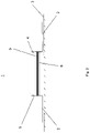
- Figure 1 shows a device 1 for application of a sensor to a measuring site.
- the device 1 comprises an application area 2 being covered with an adhesive layer.
- the adhesive layer fixes the device 1 to the skin 3.
- the device 1 further comprises a wall arrangement 5 which is oriented substantially perpendicular to the application area 2.
- the wall arrangement 5 can further exhibit different geometrical shapes such as conical elements or grooves.
- the wall arrangement 5 provides an applicator volume 7 above the skin 3.
- the wall arrangement can limit the applicator volume in a circular, elliptical or polyangular shape.
- the wall arrangement 5 is made from plastic material such as ABS or POM or other bio-compatible plastic materials in injection moulding.
- the wall arrangement could further be stamped or blanked. Furthermore, the wall arrangement 5 comprises an interface 4 which enables the connection with the sensor head.
- the interface 4 is adapted to fit into a groove being arranged on a sensor head.
- the interface 4 leads to a Poka Yoke connection of the sensor head and the device 1.
- the sensor head either fits into the device 1 in a correct manner so that measurements are possible or it does not fit at all.
- the sensor head preferably is rotatable in the device 1 during and/or after fitting them together.
- a gas permeable membrane 6 separates the applicator volume within the wall arrangement 5 into the first volume 7 being directed to the measuring site at a patients' site of the wall arrangement and a second volume 8 being separate from the patients' skin and directed to the sensor site of the wall arrangement 5.
- the membrane 6 further comprises water-impermeable properties. Of course even further layers are possible.
- the membrane 6 consists of a fluoropolymer such as PTFE.
- the membrane 6 is covered with a contact medium 11.
- Figure 2 shows a device 1 as described in figure 1 comprising an application area 2 being stuck onto the skin 3.
- the device 1 comprises a wall arrangement 5 and a gas permeable membrane 6.
- the wall arrangement further comprises an interface 4 adapted to connect the device 1 to the sensor head.
- the device 1 comprises a sensitive layer 9 being able to react to a gaseous medium diffusing from the skin 3.
- the sensitive layer 9 comprises a pH-indicator which indicates a change in the pH value based on changing partial pressures of CO 2 by a colour change.
- a sensitive layer can be a layer as disclosed in EP 1 889 050 .
- Figure 3 shows a device 1 in a clamping arrangement.
- a clamping arrangement is preferably clipped to an ear, ear lobe or ala of the nose.
- a clamping area 10 resiliently presses against the application area 2, wherein the earlobe is positioned in between the clamping area 10 and the application area 2.
- the application area 2 may be covered with an adhesive layer as well as the clamping area 10.
- the device 1 further comprises a wall arrangement 5, which is arranged substantially perpendicular to the application area 2 in use.
- a membrane 6 is arranged substantially perpendicular to the wall arrangement 5 and in parallel to the application area 2 in use.
- the wall arrangement 5 comprises an interface 4 which enables an optical sensor head to be attached to the device 1.
- a contact medium layer 11 can be added to the application area.
- the device 1 is made from POM (polyoxymethylene) or ABS (acrylonitrile butadiene styrene) in injection moulding.
- Figure 4 shows a device 1 in an adhesive arrangement.
- An adhesive arrangement can basically be stuck to a measuring site anywhere.
- the adhesive arrangement comprises an application area 2 providing an adhesive layer.
- the device 1 further comprises a wall arrangement 5 which is arranged substantially perpendicular to the application area 2.
- a membrane 6 is provided substantially in parallel to the application area 2 in use.
- the wall arrangement 5 further comprises an interface 4 which enables an optical sensor head to be attached to the device 1.
- the device is made from plastic material and cannot be dismounted without destroying the device 1.
- the membrane 6 further comprises a sensitive layer 9 which does not cover the complete membrane 6.
- the sensitive layer 9 further comprises a reflective layer.
- This embodiment is preferably used for combined measurements of colorimetric and pulse oximetric measurements or measurements of spectral properties of haemoglobin and/or myoglobin and/or bilirubin and/or water and/or acetone, ethanol or other alcohols.
Landscapes
- Health & Medical Sciences (AREA)
- Life Sciences & Earth Sciences (AREA)
- Physics & Mathematics (AREA)
- Surgery (AREA)
- General Health & Medical Sciences (AREA)
- Engineering & Computer Science (AREA)
- Biomedical Technology (AREA)
- Heart & Thoracic Surgery (AREA)
- Medical Informatics (AREA)
- Molecular Biology (AREA)
- Biophysics (AREA)
- Animal Behavior & Ethology (AREA)
- Pathology (AREA)
- Public Health (AREA)
- Veterinary Medicine (AREA)
- Optics & Photonics (AREA)
- Spectroscopy & Molecular Physics (AREA)
- Cardiology (AREA)
- Physiology (AREA)
- Pulmonology (AREA)
- Measurement Of The Respiration, Hearing Ability, Form, And Blood Characteristics Of Living Organisms (AREA)
- Investigating Or Analysing Materials By The Use Of Chemical Reactions (AREA)
- Measuring And Recording Apparatus For Diagnosis (AREA)
Claims (14)
- Dispositif (1) pour l'application d'un capteur sur un site de mesure, ledit dispositif comprenant au moins une zone d'application (2) permettant l'application du dispositif sur la peau d'un patient (3), le dispositif étant configuré comme un arrangement de serrage ayant une zone de serrage (10) qui appuie de manière élastique contre la zone d'application (2),
le dispositif ayant en outre une interface (4) pour connecter le dispositif à une tête de capteur, dans lequel le dispositif a au moins un arrangement de paroi (5) comprenant des parois qui sont perpendiculaires au site de mesure et fournissant un volume d'applicateur au-dessus de la peau du patient, dans lequel l'arrangement de paroi comprend un côté du patient et un côté du capteur, dans lequel au moins une membrane perméable aux gaz (6) sépare le volume de l'applicateur en un premier volume (7) dirigé vers le site de mesure du côté du patient de l'agencement de parois (5) et un second volume (8) séparé de la peau du patient et dirigé vers le côté capteur de l'agencement de parois (5) et au moins l'agencement de parois et la membrane ne peuvent pas être désassemblés sans être détruits, dans lequel l'interface (4) comprend un élément d'étanchéité pour isoler le second volume des gaz ambiants et du rayonnement ambiant pendant l'utilisation et dans lequel la membrane (6) du côté du patient est pourvue d'un milieu de contact, qui isole de préférence le premier volume de l'air ambiant et/ou du rayonnement ambiant, dans lequel le milieu de contact est recouvert d'une couche de couverture détachable avant l'utilisation. - Dispositif (1) selon la revendication 1, caractérisé en ce que la membrane perméable aux gaz (6) est en outre imperméable aux fluides ou le dispositif comprend une seconde membrane imperméable aux fluides.
- Dispositif (1) selon l'une quelconque des revendications précédentes, caractérisé en ce que la zone d'application ou l'agencement de paroi (5) du côté du patient est pourvu d'un médium de contact (11).
- Dispositif (1) selon l'une quelconque des revendications précédentes, caractérisé en ce que la zone d'application est recouverte d'une couche de couverture détachable avant utilisation.
- Dispositif (1) selon l'une quelconque des revendications précédentes, caractérisé en ce que le deuxième volume (8) ou la membrane perméable aux gaz (6) comprend un ou plusieurs colorants sensibles aux gaz, dans lequel de préférence une couche sensible (9) comprenant le colorant sensible est protégée par une couche de protection contre les influences environnementales telles que les gaz et la lumière ambiante avant utilisation.
- Dispositif (1) selon l'une quelconque des revendications précédentes, caractérisé en ce que la membrane perméable aux gaz (6) est au moins partiellement une couche réfléchissante, une couche blanche ou une couche métallique, ayant des propriétés réfléchissantes au moins dans une plage de longueur d'onde de 400 nm à 1 µm, ou une couche supplémentaire au moins partiellement réfléchissante, une couche blanche ou une couche métallique est prévue, ayant des propriétés réfléchissantes au moins dans une plage de longueur d'onde de 400 nm à 1 µm.
- Dispositif (1) selon l'une quelconque des revendications précédentes caractérisé en ce que le dispositif comprend des moyens d'identi- fication et/ou des données d'étalonnage.
- Dispositif (1) selon l'une quelconque des revendications précédentes, caractérisé en ce que le dispositif (1) est protégé par un emballage étanche aux gaz et à la lumière.
- Dispositif (1) selon l'une quelconque des revendications précédentes, dans lequel l'interface (4) est adaptée de telle sorte que la tête de capteur qui est insérée dans le dispositif peut encore tourner pendant qu'elle est insérée ou après, en particulier l'interface (4) est adaptée pour s'adapter dans une rainure étant disposée sur une tête de capteur.
- Utilisation d'un dispositif (1) selon l'une quelconque des revendications 1 à 9 pour des mesures transcutanées de CO2 et/ou de O2 et/ou des propriétés spectrales de l'hémoglobine et/ou pour des mesures pulsoximétriques de O2 et/ou de la vapeur d'eau et/ou des propriétés spectrales de la myoglobine et/ou de la bilirubine et/ou de l'eau et/ou de l'acétone et/ou des alcools, tels que l'éthanol.
- Kit d'une tête de capteur et d'un dispositif d'application d'un capteur sur un site de mesure selon l'une quelconque des revendications 1 à 9, où seule la combinaison de la tête de capteur et du dispositif d'application permet d'obtenir un capteur de mesure entièrement fonctionnel.
- Kit selon la revendication 11, caractérisé en ce que la tête de capteur est adaptée pour des mesures optiques colorimétriques ou fluorescentes, ou des combinaisons de celles-ci, dans lequel la couche qui n'est pas fournie par la tête de capteur mais par le dispositif est au moins une couche parmi une couche d'indication colorimétrique et fluorescente.
- Kit selon la revendication 11 ou la revendication 12, caractérisé en ce que la tête de capteur est adaptée pour des mesures optiques colorimétriques, fluorescentes ou d'absorption, dans lequel la couche n'étant pas fournie par la tête de capteur mais par le dispositif est une couche de réflexion de la lumière, ayant des propriétés de réflexion dans une plage de longueur d'onde de 400 nm à 1 µm.
- Kit selon l'une quelconque des revendications 11 à 13, dans lequel les couches qui ne sont pas fournies par la tête de capteur mais par le dispositif sont une combinaison d'une ou plusieurs couches d'indication colorimétrique ou fluorescente, d'une couche perméable aux gaz, et éventuellement aussi imperméable aux fluides, définissant un volume de mesure, et d'une couche réfléchissant la lumière, ayant des propriétés réfléchissantes dans une gamme de longueur d'onde de 400 nm à 1 µm.
Priority Applications (1)
| Application Number | Priority Date | Filing Date | Title |
|---|---|---|---|
| EP12762011.0A EP2773266B1 (fr) | 2011-10-31 | 2012-09-25 | Dispositif pour l'application d'un capteur à un site de mesure, trousse d'un dispositif d'application et d'un capteur et utilisation d'un dispositif d'application pour des mesures optiques de paramètres physiologiques |
Applications Claiming Priority (3)
| Application Number | Priority Date | Filing Date | Title |
|---|---|---|---|
| EP11187342 | 2011-10-31 | ||
| PCT/EP2012/068851 WO2013064313A1 (fr) | 2011-10-31 | 2012-09-25 | Dispositif pour l'application d'un capteur à un site de mesure, tête de capteur, trousse d'un dispositif d'application et d'un capteur et utilisation d'un dispositif d'application pour des mesures optiques de paramètres physiologiques |
| EP12762011.0A EP2773266B1 (fr) | 2011-10-31 | 2012-09-25 | Dispositif pour l'application d'un capteur à un site de mesure, trousse d'un dispositif d'application et d'un capteur et utilisation d'un dispositif d'application pour des mesures optiques de paramètres physiologiques |
Publications (2)
| Publication Number | Publication Date |
|---|---|
| EP2773266A1 EP2773266A1 (fr) | 2014-09-10 |
| EP2773266B1 true EP2773266B1 (fr) | 2022-11-30 |
Family
ID=46888471
Family Applications (1)
| Application Number | Title | Priority Date | Filing Date |
|---|---|---|---|
| EP12762011.0A Active EP2773266B1 (fr) | 2011-10-31 | 2012-09-25 | Dispositif pour l'application d'un capteur à un site de mesure, trousse d'un dispositif d'application et d'un capteur et utilisation d'un dispositif d'application pour des mesures optiques de paramètres physiologiques |
Country Status (8)
| Country | Link |
|---|---|
| US (1) | US10105065B2 (fr) |
| EP (1) | EP2773266B1 (fr) |
| JP (1) | JP2014534019A (fr) |
| CN (1) | CN104023636B (fr) |
| DK (1) | DK2773266T3 (fr) |
| HK (1) | HK1200079A1 (fr) |
| IN (1) | IN2014DN03255A (fr) |
| WO (1) | WO2013064313A1 (fr) |
Families Citing this family (10)
| Publication number | Priority date | Publication date | Assignee | Title |
|---|---|---|---|---|
| WO2013128329A1 (fr) * | 2012-03-01 | 2013-09-06 | Koninklijke Philips N.V. | Capteur pour la détermination de concentration de gaz |
| BR112015030252B1 (pt) | 2013-06-06 | 2022-04-26 | Koninklijke Philips N.V. | Unidade de sensor óptico químico para medição transcutânea de uma concentração de um gás, sistema de monitoramento de paciente e/ou ventilação de um paciente, e, método de condicionamento de um sensor óptico químico para medição transcutânea de uma concentração de um gás |
| JP6881976B2 (ja) * | 2013-06-06 | 2021-06-02 | コーニンクレッカ フィリップス エヌ ヴェKoninklijke Philips N.V. | 気体の濃度を経皮的に測定する化学−光学センサユニット、及び、そのコンディションを調整する方法 |
| WO2015010709A1 (fr) * | 2013-07-22 | 2015-01-29 | Sentec Ag | Capteur et procédé de détection d'un gaz |
| EP3024390B1 (fr) | 2013-07-22 | 2020-11-04 | Sentec Ag | Capteur de détection de gaz et procédé de détection de gaz |
| CN105578969B (zh) * | 2013-09-26 | 2019-01-22 | 3M创新有限公司 | 适用于检测在皮肤部位处的醇残留的蒸汽传感器 |
| US10772560B2 (en) * | 2016-10-02 | 2020-09-15 | Purdue Research Foundation | Skin-mounted hydration sensor and management system |
| GB2555640A (en) * | 2016-11-07 | 2018-05-09 | The Newcastle Upon Tyne Hospitals Nhs Found Trust | Sensor housing and associated disposable element |
| US20210282678A1 (en) * | 2017-03-23 | 2021-09-16 | Technion Research & Development Foundation Limited | Device and methods for detection and monitoring of tuberculosis |
| CN115844391A (zh) | 2019-01-16 | 2023-03-28 | 麦迪贝肯有限公司 | 两件式传感器组件及其使用方法 |
Citations (1)
| Publication number | Priority date | Publication date | Assignee | Title |
|---|---|---|---|---|
| US6503198B1 (en) * | 1997-09-11 | 2003-01-07 | Jack L. Aronowtiz | Noninvasive transdermal systems for detecting an analyte obtained from or underneath skin and methods |
Family Cites Families (28)
| Publication number | Priority date | Publication date | Assignee | Title |
|---|---|---|---|---|
| GB1509174A (en) | 1974-04-05 | 1978-04-26 | Searle & Co | Device for measuring blood gases |
| US4041932A (en) * | 1975-02-06 | 1977-08-16 | Fostick Moshe A | Method for monitoring blood gas tension and pH from outside the body |
| DE2508637C3 (de) | 1975-02-28 | 1979-11-22 | Max-Planck-Gesellschaft Zur Foerderung Der Wissenschaften E.V., 3400 Goettingen | Anordnung zur optischen Messung von Blutgasen |
| DK139895B (da) * | 1976-06-01 | 1979-05-14 | Radiometer As | Elektrokemisk måleelektrode til transcutan måling. |
| DE2836904C2 (de) | 1978-08-23 | 1980-07-03 | Siemens Ag, 1000 Berlin Und 8000 Muenchen | Klebehalterung |
| US4259963A (en) * | 1979-07-03 | 1981-04-07 | Albert Huch | Multi-purpose transducer for transcutaneous blood measurements |
| US4303076A (en) * | 1979-12-31 | 1981-12-01 | Air Shields, Inc. | Probe for transcutaneous sampling |
| JPS5931220Y2 (ja) | 1980-10-20 | 1984-09-05 | 住友電気工業株式会社 | 経皮血中ガスセンサ− |
| JPS5940844A (ja) | 1982-09-01 | 1984-03-06 | 萩原 文二 | 経皮血中酸素ガス及び炭酸ガス同時測定用センサ− |
| JPH0529690Y2 (fr) * | 1985-01-11 | 1993-07-29 | ||
| US4824789B1 (en) * | 1986-10-10 | 1996-08-13 | Minnesota Mining & Mfg | Gas sensor |
| US4821733A (en) * | 1987-08-18 | 1989-04-18 | Dermal Systems International | Transdermal detection system |
| JPH0395435A (ja) * | 1989-09-08 | 1991-04-19 | Terumo Corp | 測定装置 |
| JPH0933532A (ja) | 1995-07-24 | 1997-02-07 | Brother Ind Ltd | 生化学物質測定装置 |
| CA2308063A1 (fr) * | 1997-10-31 | 1999-05-14 | Technical Chemicals & Products, Inc. | Reflectometre |
| JP2000178850A (ja) | 1998-12-16 | 2000-06-27 | Murata Mach Ltd | 糸条加工ノズル |
| EP1040788B1 (fr) | 1999-03-29 | 2001-12-19 | F.Hoffmann-La Roche Ag | Dispositif pour la détermination quantative de la distribution locale d'une grandeur a mesurer |
| AT409451B (de) | 1999-12-14 | 2002-08-26 | Hoffmann La Roche | Vorrichtung zur bestimmung der örtlichen verteilung einer messgrösse |
| US20010034479A1 (en) | 2000-04-19 | 2001-10-25 | Ring Lawrence S. | Optically based transcutaneous blood gas sensor |
| DE10101576B4 (de) | 2001-01-15 | 2016-02-18 | Presens Precision Sensing Gmbh | Optischer Sensor und Sensorfeld |
| EP1776035A2 (fr) | 2004-07-01 | 2007-04-25 | Vivomedical, Inc. | Mesure non invasive du glucose |
| EP1722223A1 (fr) | 2005-05-10 | 2006-11-15 | Eidgenossisch Technische Hochschule Zürich | Membrane d'oxide metallique avec un composé présentant une sélectivité aux gaz |
| TW200829053A (en) * | 2006-12-21 | 2008-07-01 | Global Target Entpr Inc | Thin-film type sound source output apparatus |
| EP2144555B2 (fr) | 2007-04-27 | 2022-05-11 | Sentec Ag | Dispositif et procédé de détermination par voie transcutanée de gaz sanguins |
| JP2009125342A (ja) | 2007-11-26 | 2009-06-11 | National Institute Of Advanced Industrial & Technology | バイオセンサ測定装置 |
| WO2009151027A1 (fr) * | 2008-06-10 | 2009-12-17 | 株式会社日立製作所 | Dispositif d’authentification de personne |
| US9511196B2 (en) * | 2009-12-31 | 2016-12-06 | Ohio University | Systems and methods for promoting wound healing |
| WO2012121260A1 (fr) * | 2011-03-08 | 2012-09-13 | 株式会社 エヌ・ティ・ティ・ドコモ | Dispositif porté sur le corps et dispositif et procédé pour mesurer un gaz biologique |
-
2012
- 2012-09-25 IN IN3255DEN2014 patent/IN2014DN03255A/en unknown
- 2012-09-25 US US14/351,276 patent/US10105065B2/en active Active
- 2012-09-25 DK DK12762011.0T patent/DK2773266T3/da active
- 2012-09-25 JP JP2014537540A patent/JP2014534019A/ja active Pending
- 2012-09-25 WO PCT/EP2012/068851 patent/WO2013064313A1/fr active Application Filing
- 2012-09-25 EP EP12762011.0A patent/EP2773266B1/fr active Active
- 2012-09-25 CN CN201280053285.4A patent/CN104023636B/zh active Active
-
2015
- 2015-01-21 HK HK15100722.8A patent/HK1200079A1/xx unknown
Patent Citations (1)
| Publication number | Priority date | Publication date | Assignee | Title |
|---|---|---|---|---|
| US6503198B1 (en) * | 1997-09-11 | 2003-01-07 | Jack L. Aronowtiz | Noninvasive transdermal systems for detecting an analyte obtained from or underneath skin and methods |
Non-Patent Citations (1)
| Title |
|---|
| CHIOU J. S. ET AL: "Gas permeation in polyethersulfone", JOURNAL OF APPLIED POLYMER SCIENCE, vol. 33, no. 5, 1 April 1987 (1987-04-01), US, pages 1823 - 1828, XP055872208, ISSN: 0021-8995, DOI: 10.1002/app.1987.070330533 * |
Also Published As
| Publication number | Publication date |
|---|---|
| CN104023636A (zh) | 2014-09-03 |
| DK2773266T3 (da) | 2023-02-13 |
| JP2014534019A (ja) | 2014-12-18 |
| US10105065B2 (en) | 2018-10-23 |
| EP2773266A1 (fr) | 2014-09-10 |
| HK1200079A1 (en) | 2015-07-31 |
| IN2014DN03255A (fr) | 2015-05-22 |
| WO2013064313A1 (fr) | 2013-05-10 |
| US20140303462A1 (en) | 2014-10-09 |
| CN104023636B (zh) | 2017-03-15 |
Similar Documents
| Publication | Publication Date | Title |
|---|---|---|
| EP2773266B1 (fr) | Dispositif pour l'application d'un capteur à un site de mesure, trousse d'un dispositif d'application et d'un capteur et utilisation d'un dispositif d'application pour des mesures optiques de paramètres physiologiques | |
| US7135342B2 (en) | Electro-optical sensing device with reference channel | |
| RU2653633C2 (ru) | Датчик определения концентрации газа | |
| US20090075321A1 (en) | Fibre optic sensor | |
| US10161871B2 (en) | Chemically stable sensing unit with protector element | |
| US20070106134A1 (en) | Medical sensor and technique for using the same | |
| KR20120000102A (ko) | 분석물의 검출을 위한 광전자 방법 및 장치 | |
| EP0363472A1 (fr) | Detecteur quantitatif de dioxyde de carbone | |
| EP3333568B1 (fr) | Capteur optochimique | |
| US20150147231A1 (en) | Optochemical sensor | |
| US11971360B2 (en) | Optochemical sensor and method for measured value correction | |
| US4280505A (en) | Fixation ring for transcutaneous gas sensor probe | |
| US20030221477A1 (en) | Cartridge for packaging a sensor in a fluid calibrant | |
| EP2150176B1 (fr) | Détecteur de concentration implantable et dispositif | |
| US20120148452A1 (en) | Non invasive gas analysis | |
| JP2011085538A (ja) | ガスセンサ | |
| KR20220027985A (ko) | 매체의 멀티 파라미터 분석을 위한 센서 모듈 | |
| JP4246396B2 (ja) | Co2センサ用のセンサカプセル | |
| CA2628699A1 (fr) | Sonde de fin de duree de vie pour appareil respiratoire | |
| EP3227668B1 (fr) | Dispositif de capteur optique | |
| US8993972B2 (en) | Fluorescence based sensors utilizing a mirrored cavity | |
| JP2005164575A (ja) | ガス検知材、及びこれに適したガス検出装置 | |
| EP1626269B1 (fr) | Dispositif de mesure d'un composant | |
| US7894069B2 (en) | Respirator end-of-service life probe | |
| JP2009020026A (ja) | 検査シート |
Legal Events
| Date | Code | Title | Description |
|---|---|---|---|
| PUAI | Public reference made under article 153(3) epc to a published international application that has entered the european phase |
Free format text: ORIGINAL CODE: 0009012 |
|
| STAA | Information on the status of an ep patent application or granted ep patent |
Free format text: STATUS: REQUEST FOR EXAMINATION WAS MADE |
|
| 17P | Request for examination filed |
Effective date: 20140401 |
|
| AK | Designated contracting states |
Kind code of ref document: A1 Designated state(s): AL AT BE BG CH CY CZ DE DK EE ES FI FR GB GR HR HU IE IS IT LI LT LU LV MC MK MT NL NO PL PT RO RS SE SI SK SM TR |
|
| DAX | Request for extension of the european patent (deleted) | ||
| STAA | Information on the status of an ep patent application or granted ep patent |
Free format text: STATUS: EXAMINATION IS IN PROGRESS |
|
| 17Q | First examination report despatched |
Effective date: 20210319 |
|
| STAA | Information on the status of an ep patent application or granted ep patent |
Free format text: STATUS: EXAMINATION IS IN PROGRESS |
|
| GRAP | Despatch of communication of intention to grant a patent |
Free format text: ORIGINAL CODE: EPIDOSNIGR1 |
|
| STAA | Information on the status of an ep patent application or granted ep patent |
Free format text: STATUS: GRANT OF PATENT IS INTENDED |
|
| INTG | Intention to grant announced |
Effective date: 20220721 |
|
| GRAS | Grant fee paid |
Free format text: ORIGINAL CODE: EPIDOSNIGR3 |
|
| GRAA | (expected) grant |
Free format text: ORIGINAL CODE: 0009210 |
|
| STAA | Information on the status of an ep patent application or granted ep patent |
Free format text: STATUS: THE PATENT HAS BEEN GRANTED |
|
| AK | Designated contracting states |
Kind code of ref document: B1 Designated state(s): AL AT BE BG CH CY CZ DE DK EE ES FI FR GB GR HR HU IE IS IT LI LT LU LV MC MK MT NL NO PL PT RO RS SE SI SK SM TR |
|
| REG | Reference to a national code |
Ref country code: CH Ref legal event code: EP Ref country code: GB Ref legal event code: FG4D |
|
| REG | Reference to a national code |
Ref country code: AT Ref legal event code: REF Ref document number: 1534052 Country of ref document: AT Kind code of ref document: T Effective date: 20221215 Ref country code: DE Ref legal event code: R096 Ref document number: 602012079062 Country of ref document: DE |
|
| REG | Reference to a national code |
Ref country code: IE Ref legal event code: FG4D |
|
| REG | Reference to a national code |
Ref country code: DK Ref legal event code: T3 Effective date: 20230209 |
|
| REG | Reference to a national code |
Ref country code: LT Ref legal event code: MG9D |
|
| REG | Reference to a national code |
Ref country code: NL Ref legal event code: MP Effective date: 20221130 |
|
| PG25 | Lapsed in a contracting state [announced via postgrant information from national office to epo] |
Ref country code: SE Free format text: LAPSE BECAUSE OF FAILURE TO SUBMIT A TRANSLATION OF THE DESCRIPTION OR TO PAY THE FEE WITHIN THE PRESCRIBED TIME-LIMIT Effective date: 20221130 Ref country code: PT Free format text: LAPSE BECAUSE OF FAILURE TO SUBMIT A TRANSLATION OF THE DESCRIPTION OR TO PAY THE FEE WITHIN THE PRESCRIBED TIME-LIMIT Effective date: 20230331 Ref country code: NO Free format text: LAPSE BECAUSE OF FAILURE TO SUBMIT A TRANSLATION OF THE DESCRIPTION OR TO PAY THE FEE WITHIN THE PRESCRIBED TIME-LIMIT Effective date: 20230228 Ref country code: LT Free format text: LAPSE BECAUSE OF FAILURE TO SUBMIT A TRANSLATION OF THE DESCRIPTION OR TO PAY THE FEE WITHIN THE PRESCRIBED TIME-LIMIT Effective date: 20221130 Ref country code: FI Free format text: LAPSE BECAUSE OF FAILURE TO SUBMIT A TRANSLATION OF THE DESCRIPTION OR TO PAY THE FEE WITHIN THE PRESCRIBED TIME-LIMIT Effective date: 20221130 Ref country code: ES Free format text: LAPSE BECAUSE OF FAILURE TO SUBMIT A TRANSLATION OF THE DESCRIPTION OR TO PAY THE FEE WITHIN THE PRESCRIBED TIME-LIMIT Effective date: 20221130 |
|
| REG | Reference to a national code |
Ref country code: AT Ref legal event code: MK05 Ref document number: 1534052 Country of ref document: AT Kind code of ref document: T Effective date: 20221130 |
|
| PG25 | Lapsed in a contracting state [announced via postgrant information from national office to epo] |
Ref country code: RS Free format text: LAPSE BECAUSE OF FAILURE TO SUBMIT A TRANSLATION OF THE DESCRIPTION OR TO PAY THE FEE WITHIN THE PRESCRIBED TIME-LIMIT Effective date: 20221130 Ref country code: PL Free format text: LAPSE BECAUSE OF FAILURE TO SUBMIT A TRANSLATION OF THE DESCRIPTION OR TO PAY THE FEE WITHIN THE PRESCRIBED TIME-LIMIT Effective date: 20221130 Ref country code: LV Free format text: LAPSE BECAUSE OF FAILURE TO SUBMIT A TRANSLATION OF THE DESCRIPTION OR TO PAY THE FEE WITHIN THE PRESCRIBED TIME-LIMIT Effective date: 20221130 Ref country code: IS Free format text: LAPSE BECAUSE OF FAILURE TO SUBMIT A TRANSLATION OF THE DESCRIPTION OR TO PAY THE FEE WITHIN THE PRESCRIBED TIME-LIMIT Effective date: 20230330 Ref country code: HR Free format text: LAPSE BECAUSE OF FAILURE TO SUBMIT A TRANSLATION OF THE DESCRIPTION OR TO PAY THE FEE WITHIN THE PRESCRIBED TIME-LIMIT Effective date: 20221130 Ref country code: GR Free format text: LAPSE BECAUSE OF FAILURE TO SUBMIT A TRANSLATION OF THE DESCRIPTION OR TO PAY THE FEE WITHIN THE PRESCRIBED TIME-LIMIT Effective date: 20230301 |
|
| PG25 | Lapsed in a contracting state [announced via postgrant information from national office to epo] |
Ref country code: NL Free format text: LAPSE BECAUSE OF FAILURE TO SUBMIT A TRANSLATION OF THE DESCRIPTION OR TO PAY THE FEE WITHIN THE PRESCRIBED TIME-LIMIT Effective date: 20221130 |
|
| PG25 | Lapsed in a contracting state [announced via postgrant information from national office to epo] |
Ref country code: SM Free format text: LAPSE BECAUSE OF FAILURE TO SUBMIT A TRANSLATION OF THE DESCRIPTION OR TO PAY THE FEE WITHIN THE PRESCRIBED TIME-LIMIT Effective date: 20221130 Ref country code: RO Free format text: LAPSE BECAUSE OF FAILURE TO SUBMIT A TRANSLATION OF THE DESCRIPTION OR TO PAY THE FEE WITHIN THE PRESCRIBED TIME-LIMIT Effective date: 20221130 Ref country code: EE Free format text: LAPSE BECAUSE OF FAILURE TO SUBMIT A TRANSLATION OF THE DESCRIPTION OR TO PAY THE FEE WITHIN THE PRESCRIBED TIME-LIMIT Effective date: 20221130 Ref country code: CZ Free format text: LAPSE BECAUSE OF FAILURE TO SUBMIT A TRANSLATION OF THE DESCRIPTION OR TO PAY THE FEE WITHIN THE PRESCRIBED TIME-LIMIT Effective date: 20221130 Ref country code: AT Free format text: LAPSE BECAUSE OF FAILURE TO SUBMIT A TRANSLATION OF THE DESCRIPTION OR TO PAY THE FEE WITHIN THE PRESCRIBED TIME-LIMIT Effective date: 20221130 |
|
| PG25 | Lapsed in a contracting state [announced via postgrant information from national office to epo] |
Ref country code: SK Free format text: LAPSE BECAUSE OF FAILURE TO SUBMIT A TRANSLATION OF THE DESCRIPTION OR TO PAY THE FEE WITHIN THE PRESCRIBED TIME-LIMIT Effective date: 20221130 Ref country code: AL Free format text: LAPSE BECAUSE OF FAILURE TO SUBMIT A TRANSLATION OF THE DESCRIPTION OR TO PAY THE FEE WITHIN THE PRESCRIBED TIME-LIMIT Effective date: 20221130 |
|
| REG | Reference to a national code |
Ref country code: DE Ref legal event code: R097 Ref document number: 602012079062 Country of ref document: DE |
|
| PLBE | No opposition filed within time limit |
Free format text: ORIGINAL CODE: 0009261 |
|
| STAA | Information on the status of an ep patent application or granted ep patent |
Free format text: STATUS: NO OPPOSITION FILED WITHIN TIME LIMIT |
|
| PGFP | Annual fee paid to national office [announced via postgrant information from national office to epo] |
Ref country code: GB Payment date: 20230824 Year of fee payment: 12 |
|
| 26N | No opposition filed |
Effective date: 20230831 |
|
| PG25 | Lapsed in a contracting state [announced via postgrant information from national office to epo] |
Ref country code: SI Free format text: LAPSE BECAUSE OF FAILURE TO SUBMIT A TRANSLATION OF THE DESCRIPTION OR TO PAY THE FEE WITHIN THE PRESCRIBED TIME-LIMIT Effective date: 20221130 |
|
| PGFP | Annual fee paid to national office [announced via postgrant information from national office to epo] |
Ref country code: FR Payment date: 20230821 Year of fee payment: 12 Ref country code: DK Payment date: 20230914 Year of fee payment: 12 Ref country code: DE Payment date: 20230822 Year of fee payment: 12 |
|
| PGFP | Annual fee paid to national office [announced via postgrant information from national office to epo] |
Ref country code: CH Payment date: 20231201 Year of fee payment: 12 |
|
| PG25 | Lapsed in a contracting state [announced via postgrant information from national office to epo] |
Ref country code: LU Free format text: LAPSE BECAUSE OF NON-PAYMENT OF DUE FEES Effective date: 20230925 |