EP2772174B1 - Staubsauger-saugrohr - Google Patents
Staubsauger-saugrohr Download PDFInfo
- Publication number
- EP2772174B1 EP2772174B1 EP14157105.9A EP14157105A EP2772174B1 EP 2772174 B1 EP2772174 B1 EP 2772174B1 EP 14157105 A EP14157105 A EP 14157105A EP 2772174 B1 EP2772174 B1 EP 2772174B1
- Authority
- EP
- European Patent Office
- Prior art keywords
- vacuum cleaner
- cleaner suction
- latching
- suction tube
- projection
- Prior art date
- Legal status (The legal status is an assumption and is not a legal conclusion. Google has not performed a legal analysis and makes no representation as to the accuracy of the status listed.)
- Active
Links
- 239000000463 material Substances 0.000 claims description 10
- 239000004033 plastic Substances 0.000 description 8
- 229920003023 plastic Polymers 0.000 description 8
- 230000005540 biological transmission Effects 0.000 description 5
- 230000037431 insertion Effects 0.000 description 3
- 238000003780 insertion Methods 0.000 description 3
- 229910001220 stainless steel Inorganic materials 0.000 description 3
- 239000010935 stainless steel Substances 0.000 description 3
- 229930040373 Paraformaldehyde Natural products 0.000 description 2
- 239000004743 Polypropylene Substances 0.000 description 2
- 229920006324 polyoxymethylene Polymers 0.000 description 2
- -1 polypropylene Polymers 0.000 description 2
- 229920001155 polypropylene Polymers 0.000 description 2
- 239000011324 bead Substances 0.000 description 1
- 230000000694 effects Effects 0.000 description 1
- 238000009434 installation Methods 0.000 description 1
- 238000007789 sealing Methods 0.000 description 1
- 230000007704 transition Effects 0.000 description 1
- 238000009827 uniform distribution Methods 0.000 description 1
Images

Classifications
-
- A—HUMAN NECESSITIES
- A47—FURNITURE; DOMESTIC ARTICLES OR APPLIANCES; COFFEE MILLS; SPICE MILLS; SUCTION CLEANERS IN GENERAL
- A47L—DOMESTIC WASHING OR CLEANING; SUCTION CLEANERS IN GENERAL
- A47L9/00—Details or accessories of suction cleaners, e.g. mechanical means for controlling the suction or for effecting pulsating action; Storing devices specially adapted to suction cleaners or parts thereof; Carrying-vehicles specially adapted for suction cleaners
- A47L9/24—Hoses or pipes; Hose or pipe couplings
- A47L9/242—Hose or pipe couplings
-
- A—HUMAN NECESSITIES
- A47—FURNITURE; DOMESTIC ARTICLES OR APPLIANCES; COFFEE MILLS; SPICE MILLS; SUCTION CLEANERS IN GENERAL
- A47L—DOMESTIC WASHING OR CLEANING; SUCTION CLEANERS IN GENERAL
- A47L9/00—Details or accessories of suction cleaners, e.g. mechanical means for controlling the suction or for effecting pulsating action; Storing devices specially adapted to suction cleaners or parts thereof; Carrying-vehicles specially adapted for suction cleaners
- A47L9/24—Hoses or pipes; Hose or pipe couplings
- A47L9/248—Parts, details or accessories of hoses or pipes
Definitions
- the invention relates to a vacuum cleaner suction pipe, with at least one locking projection, the locking projection being formed in an end region of the vacuum cleaner suction tube, and wherein the locking projection is formed from the material of the vacuum cleaner suction tube.
- Vacuum cleaner suction pipes are known in the prior art in a variety of configurations.
- Vacuum cleaner suction pipes are often made of a stainless steel, with attachment elements, for example made of plastic, being attached at least in the two end regions of a vacuum cleaner suction pipe.
- the add-on elements are advantageously pushed onto the vacuum cleaner suction pipe or pushed into the vacuum cleaner suction pipe. A particular requirement is the leak-free seal between the vacuum cleaner suction pipe and the add-on element.
- the WO 02/00087 A1 shows a plug-in vacuum cleaner pipe arrangement with a tubular nozzle socket, a sleeve part and a pipe insertion end of a suction pipe.
- a tongue-like component is used to lock the parts together.
- a resilient locking body with a conical cross section is provided, which can engage in recesses in the nozzle socket and the pipe insertion end in order to securely connect them to one another.
- a stop is provided on the nozzle socket, which corresponds to a longitudinal bead at the pipe insertion end, which is guided through a groove in the socket part.
- the vacuum cleaner suction pipes known from the prior art often have the disadvantage that a reliable seal, in particular when certain plastics are used for the attachment elements, cannot be adequately ensured between the vacuum cleaner suction pipe and the attachment element.
- the invention is therefore based on the object of specifying a vacuum cleaner suction tube which is reliable and allows a leak-free connection to an add-on element when using any type of plastic for the add-on element.
- the aforementioned task is first and essentially achieved in a vacuum cleaner suction pipe according to the invention in that the latching projection is formed on the outside, starting from the central axis of the vacuum cleaner suction pipe, in that the latching projection has a latching edge, that the latching edge lies in a plane whose plane normal is the central axis of the vacuum cleaner suction pipe, and that the latching edge is arranged on the side of the latching projection facing away from the end region.
- the vacuum cleaner suction pipe consequently has in an end region, preferably in the end region oriented on the bottom in the state of use, for fastening, for example, an add-on element, for. B. a nozzle or a nozzle, at least one locking projection which is formed from the material of the vacuum cleaner suction pipe.
- the material of the vacuum cleaner suction pipe is preferably brought into the shape of the locking projection by local plastic deformation.
- the locking projection is consequently formed in the direction away from the central axis of the vacuum cleaner suction tube.
- the latching projection which is formed on the outside, consequently increases the outer circumference of the vacuum cleaner suction pipe in the region of the latching projection.
- the latching projection is formed outwards from the surface of the vacuum cleaner suction tube - from the original surface.
- “Starting from the central axis” means that the locking projection is formed outwards from a viewing direction starting from the central axis from the material of the vacuum cleaner suction tube.
- the latching projection is shaped outwards in an end region of the vacuum cleaner suction pipe
- the power transmission between the add-on element made of plastic and the vacuum cleaner suction pipe is improved, so that an increased sealing effect is achieved.
- the improved power transmission enables the use of polypropylene (PP) as plastic for the add-on elements, so that expensive plastics such as polyoxymethylene (POM) can be dispensed with.
- PP polypropylene
- POM polyoxymethylene
- connection between an add-on element and the vacuum cleaner suction pipe is made, for example, in that the latching projection on the vacuum cleaner suction pipe engages in a form-fitting manner in a correspondingly formed snap-in recess on the add-on element, thereby producing a reliable snap-in connection between the vacuum cleaner suction pipe and the add-on element.
- the latching projection has a latching edge and that the latching edge is formed orthogonal to the surface of the vacuum cleaner suction pipe, in particular that the latching edge is arranged on the side of the latching projection facing away from the end region.
- the latching edge is consequently arranged orthogonally on the surface of the vacuum cleaner suction pipe and thus lies in a plane whose plane normal is the central axis of the vacuum cleaner suction pipe.
- the latching edge is formed on the side of the latching projection facing away from the end region, so that a mounting element can be clamped in the assembled state between the end face of the vacuum cleaner suction pipe and the latching projection or the latching projections.
- the locking edge of the locking projection and the end face of the vacuum cleaner suction tube are preferably arranged in mutually parallel planes.
- the angle between the locking edge and the top of the locking projection is advantageously about 90 °.
- the locking projection is not designed to prevent rotation between the attachment element and the vacuum cleaner suction pipe.
- a rotation of the attachment element relative to the vacuum cleaner suction pipe is preferably prevented in that the cross section of the vacuum cleaner suction pipe is not rotationally symmetrical, that is to say for example at least partially has different radii, in particular namely at least in sections is parabolic.
- the locking projection is now made of the material of the vacuum cleaner suction pipe, so that it has increased stability, since it - for example - like the vacuum cleaner suction pipe - made of a stainless steel is.
- the locking projection is for producing a positive connection with an attachment, z. B. a nozzle socket, provided, the attachment being pushed onto the vacuum cleaner suction pipe.
- the positive connection is inseparable when the vacuum cleaner suction pipe is used as intended.
- the add-on element is fixed in place by the locking with the locking projection.
- the stability of the connection between the vacuum cleaner suction pipe and an attachment element is increased according to the invention in that at least one second locking projection is formed in the end region on the vacuum cleaner suction pipe.
- the second latching projection is preferably identical to the first latching projection and also latches in a second latching recess formed on an attachment element for the second latching projection. It is advantageously provided that at most two locking projections are provided in the end region.
- first latching projection and the second latching projection are arranged opposite one another on the circumference of the vacuum cleaner suction pipe.
- Such an arrangement of the first locking projection and the second locking projection results in an advantageous, uniform distribution of the power transmission from the attachment element to the vacuum cleaner suction pipe.
- the first latching projection and the second latching projection preferably lie on an imaginary connecting line which connects the first latching projection, the central axis of the vacuum cleaner suction pipe and the second latching projection.
- the distance between the top of the first locking projection and the top of the second locking projection is between 38 mm and 45 mm.
- the latching projection has a run-on slope that is oriented in the direction of the end area, so that the height of the run-up slope increases with increasing distance from the end area.
- the locking projection has a saddle surface between the end of the run-on slope and the locking edge.
- the saddle surface is in particular formed parallel to the surface of the vacuum cleaner suction pipe.
- the saddle surface lies in a plane that is arranged orthogonally to the plane of the latching edge.
- the angle between the saddle surface and the locking edge is preferably approximately 90 °.
- the length of the saddle surface that is to say the distance between the end of the run-on slope and the latching edge, is preferably between 1 mm and 2 mm, particularly preferably about 1.4 mm.
- the run-on slope has an inclination between 12 ° and 20 °, and an inclination of approximately 16 ° has proven to be particularly advantageous for simple installation.
- the start of the run-on slope has a distance of approximately 4 mm from the end edge of the vacuum cleaner suction pipe.
- An advantageous power transmission between the vacuum cleaner suction pipe and the attachment element can be achieved according to a further embodiment in that the height of the latching edge is between 0.6 mm and 1 mm. It has also been found that a reliable connection can be ensured if the distance between the end face of the vacuum cleaner suction pipe and the latching edge is between 7 mm and 9 mm, in particular 8 mm.
- the latching projection has a width between 5 mm and 20 mm.
- the width of the latching projection means in particular the extent of the latching projection on the circumference of the vacuum cleaner suction pipe. A width of 10 mm is particularly advantageous.
- an attachment element is included, that the attachment element is pushed onto the end of the vacuum cleaner suction pipe, that the attachment element has at least one detent recess on its inner circumference, that the detent recess is positively locked with the detent projection , by the detent recess at least partially abuts the detent edge, and that Add-on element is designed in such a way that the positive locking cannot be released.
- the positive locking is not releasable in that the add-on element has no means for releasing the positive connection.
- the add-on element consequently has at least one locking recess on its inner circumference, which is locked with the locking projection. The latching is therefore unsolvable.
- non-releasable means that the latching can be released using tools and / or by destroying the vacuum cleaner suction pipe or the attachment element, but cannot be released when used as intended. It is not intended to release the catch during use.
- the attachment element preferably has two latching recesses, which are designed to correspond to two latching projections arranged opposite one another and are latched to them.
- connection is established in that the attachment element is pushed onto the end of the vacuum cleaner suction pipe, the material of the attachment element being elastically deformed at least temporarily - in the area of the latching projection or the latching projections - until the latching projection positively latches with the latching recess. Afterwards, loosening is not provided and is not possible without tools. A release of the locking is prevented in particular by the locking edge.
- the attachment element has on its inner circumference a counter edge for the end face of the vacuum cleaner suction pipe, and that the attachment element is clamped between the end face and the locking edge.
- the attachment element rests with its opposite edge on the end face of the vacuum cleaner suction pipe.
- the locking edge lies in the locking recess, so that the attachment element is reliably fixed in its position.
- the opposite edge is preferably all-round, so that the front edge lies completely against the opposite edge.
- the attachment element is a socket, in particular a nozzle connection socket, and that the socket has at least one latching recess for latching with a suction tool.
- the nozzle which is locked with the vacuum cleaner suction pipe is consequently designed to to be locked with a suction tool, for example a floor nozzle.
- the socket has at least one locking recess in its outer circumference, into which a locking projection of a suction tool can engage for positive locking.
- the nozzle is also designed to be inserted into a suction tool.
- the cross section of the vacuum cleaner suction pipe has at least two areas, namely an arc-shaped first area and a parabolic second area.
- This cross section is particularly provided where the locking projection is arranged. These areas result in the vacuum cleaner suction tube having a cross section that is not rotationally symmetrical, which improves the stability.
- this shape of the cross section helps to prevent rotation of the attachment element relative to the vacuum cleaner suction pipe.
- the parabolic region preferably forms a lower region of the cross section, the arcuate region forming an upper region of the cross section covering the parabolic region.
- the arcuate area extends in particular over about 1/3 of the circumference, the parabolic area over 2/3 of the circumference.
- the cross section of the vacuum cleaner suction tube is preferably mirror-symmetrical to a plane in which the central axis and the at least one latching projection, in particular both latching projections, lie.
- the circular arc-shaped area preferably has a radius of approximately 30 mm, while the radii in the parabolic area vary between 30 mm and 60 mm.
- a radius between 4 mm and 8 mm, in particular 5 mm, is preferably formed in the two transition regions between the first region and the second region.
- a locking projection on a vacuum cleaner suction tube which bulges outwards from the central axis or the surface of a vacuum cleaner suction tube, is particularly preferred for the permanent attachment of add-on elements to the vacuum cleaner suction tube.
- Advantageous add-on elements are, for example, connecting pieces which are pushed onto the vacuum cleaner suction pipe in the end region and are used to connect floor nozzles or the like.
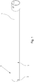
- Fig. 1 shows an embodiment of a vacuum cleaner suction pipe 1 in a perspective side view.
- the vacuum cleaner suction pipe 1 has a locking projection 2 which is arranged in an end region 3 of the vacuum cleaner suction pipe 1.
- the locking projection 2 is formed from the material of the vacuum cleaner suction pipe 1. In this embodiment, the material is stainless steel.
- the latching projection 2 is consequently formed on the outside, starting from the surface 4 of the vacuum cleaner suction pipe 1, so that the latching projection 2 locally increases the circumference of the vacuum cleaner suction pipe 1 in the end region 3.
- the locking projection 2 is completely closed, so that no leakage air can penetrate into the vacuum cleaner suction pipe 1 from the outside.
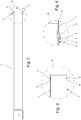
- Fig. 2 shows the embodiment according to Fig. 1 in a side view.
- a second locking projection 2 is provided on the vacuum cleaner suction pipe 1, which in this exemplary embodiment is arranged opposite one another on the circumference of the vacuum cleaner suction pipe 1.
- the first locking projection 2 and the second locking projection 2 consequently lie on an imaginary connecting line, which also includes the central axis of the vacuum cleaner suction pipe 1.
- Fig. 3 shows an enlargement of area A of Fig. 2 , which shows the opposite arrangement on the circumference of the vacuum cleaner suction tube 1 of the locking projections 2.
- Fig. 3 shows the area A of the vacuum cleaner suction pipe 1 in a sectional view.
- the latching projections 2 each have a latching edge 5, which is arranged on the side of the respective latching projection 2 facing away from the end region 3.
- the locking edge 5 lies in a plane whose normal to the plane is the central axis of the vacuum cleaner suction pipe 1.
- the central axis of the vacuum cleaner suction pipe 1 consequently passes through this plane orthogonally.
- Fig. 4 shows an enlarged and cut section of area B of the Fig. 2.
- Fig. 4 it can be seen that the latching projection 2 opposite the latching edge 5 has a run-on bevel 6, which in the assembly of a - in the 5 to 7 - Attachment element serves to perform this on the locking projection 2, so that a locking recess provided in the mounting element can lock with the locking projection 2.
- the locking projection 2 is formed outwards, that is to say away from the central axis of the vacuum cleaner suction pipe 1.
- a saddle surface 7 is formed between the end of the chamfer 6 and the locking edge 5. The angle between the saddle surface 7 and the locking edge 5 is 90 °.
- Fig. 5 shows an embodiment of a vacuum cleaner suction pipe 1, which is locked with a mounting element 8.
- the two locking projections 2 are positively locked with corresponding locking recesses on the inner circumference of the attachment element 8.
- Fig. 6 shows an enlargement of a Range Fig. 5 .
- the latching projection 2 is positively latched with the latching recess, the connection being undetachable since the attachment element has no means for releasing the latching.
- the locking arrangement is additionally stabilized by the opposite arrangement of the locking projections 2.
- the add-on element 8 also has a circumferential counter edge 9 on its inner circumference, which cooperates with the end face of the vacuum cleaner suction pipe 1, so that the add-on element is clamped between the end face and the latching edge 5.
- Fig. 7 shows an embodiment of a vacuum cleaner suction pipe 1, which is locked with a mounting element 8.
- the attachment element 8 is designed as a nozzle connecting piece and additionally has a latching recess 10 which is provided for latching with a suction tool (not shown).
Landscapes
- Engineering & Computer Science (AREA)
- Mechanical Engineering (AREA)
- Electric Suction Cleaners (AREA)
- Electric Vacuum Cleaner (AREA)
- Auxiliary Devices For Machine Tools (AREA)
Description
- Die Erfindung betrifft ein Staubsauger-Saugrohr, mit mindestens einem Rastvorsprung, wobei der Rastvorsprung in einem Endbereich des Staubsauger-Saugrohrs ausgebildet ist, und wobei der Rastvorsprung aus dem Material des Staubsauger-Saugrohrs ausgeformt ist.
- Staubsauger-Saugrohre sind im Stand der Technik in einer Vielzahl von Ausgestaltungen bekannt. Staubsauger-Saugrohre sind häufig aus einem rostfreien Stahl hergestellt, wobei zumindest in den beiden Endbereichen eines Staubsauger-Saugrohrs Anbauelemente, beispielsweise aus Kunststoff, befestigt sind. Die Anbauelemente werden dabei vorteilhaft auf das Staubsauger-Saugrohr aufgeschoben oder in das Staubsauger-Saugrohr eingeschoben. Eine besondere Anforderung ist dabei die leckagefreie Abdichtung zwischen Staubsauger-Saugrohr und dem Anbauelement.
- Die
WO 02/00087 A1 - Die aus dem Stand der Technik bekannten Staubsauger-Saugrohre weisen häufig den Nachteil auf, dass eine zuverlässige Abdichtung, insbesondere bei der Verwendung von bestimmten Kunststoffen für die Anbauelemente, zwischen Staubsauger-Saugrohr und dem Anbauelement nicht ausreichend sichergestellt werden kann.
- Ausgehend von dem vorgenannten Stand der Technik liegt der Erfindung daher die Aufgabe zugrunde, ein Staubsauger-Saugrohr anzugeben, das eine zuverlässige und leckagefreie Verbindung mit einem Anbauelement bei Verwendung jeglicher Kunststoffarten für das Anbauelement ermöglicht.
- Die vorgenannte Aufgabe ist zunächst und im Wesentlichen bei einem erfindungsgemäßen Staubsauger-Saugrohr dadurch gelöst, dass der Rastvorsprung ausgehend von der Mittelachse des Staubsauger-Saugrohrs nach außen ausgebildet ist, dass der Rastvorsprung eine Rastkante aufweist, dass die Rastkante in einer Ebene liegt, deren Ebenennormale die Mittelachse des Staubsauger-Saugrohrs ist, und dass die Rastkante auf der von der Endbereich weggewandten Seite des Rastvorsprungs angeordnet ist.
- Das Staubsauger-Saugrohr weist folglich in einem Endbereich, vorzugsweise in dem im Benutzungszustand bodenseitig orientierten Endbereich, zur Befestigung beispielsweise eines Anbauelements, z. B. eines Stutzens oder einer Düse, mindestens einen Rastvorsprung auf, der aus dem Material des Staubsauger-Saugrohrs ausgebildet ist. Vorzugsweise wird das Material des Staubsauger-Saugrohrs durch lokales plastisches Verformen in die Form des Rastvorsprungs gebracht. Der Rastvorsprung ist folglich in Richtung von der Mittelachse des Staubsauger-Saugrohrs weg, nach außen ausgebildet. Durch den Rastvorsprung, der nach außen ausgebildet ist, wird folglich der äußere Umfang des Staubsauger-Saugrohrs im Bereich des Rastvorsprungs vergrößert. Anders gesagt, ist der Rastvorsprung ausgehend von der Oberfläche des Staubsauger-Saugrohrs - aus ursprünglichen Oberfläche - nach außen ausgebildet. "Ausgehend von der Mittelachse" bedeutet, dass der Rastvorsprung von einer Betrachtungsrichtung ausgehend von der Mittelachse aus dem Material des Staubsauger-Saugrohrs nach außen ausgebildet ist.
- Dadurch, dass der Rastvorsprung in einem Endbereich des Staubsauger-Saugrohrs nach außen geformt ist, wird die Kraftübertragung zwischen dem Anbauelement aus Kunststoff und dem Staubsauger-Saugrohr verbessert, so dass eine gesteigerte Dichtwirkung erzielt wird. Des Weiteren ist aufgrund der verbesserten Kraftübertragung die Verwendung von Polypropylen (PP) als Kunststoff für die Anbauelemente ermöglicht, so dass auf teure Kunststoffe, wie beispielsweise Polyoxymethylen (POM) verzichtet werden kann. Insgesamt lässt sich durch Verwendung eines nach außen gewölbten Rastvorsprungs eine größere Robustheit der Verbindung zwischen Staubsauger-Saugrohr und einem Anbauelement aus Kunststoff, beispielsweise eines Stutzens für eine Bodendüse, erzielen.
- Die Verbindung zwischen einem Anbauelement und dem Staubsauger-Saugrohr wird beispielsweise dadurch hergestellt, dass der Rastvorsprung am Staubsauger-Saugrohr in eine entsprechend am Anbauelement ausgeformten Rastrücksprung - Tasche - formschlüssig eingreift, wodurch eine zuverlässige Rastverbindung zwischen Staubsauger-Saugrohr und Anbauelement hergestellt wird.
- Es ist vorgesehen, dass der Rastvorsprung eine Rastkante aufweist, und dass die Rastkante orthogonal zur Oberfläche des Staubsauger-Saugrohrs ausgebildet ist, insbesondere dass die Rastkante auf der von dem Endbereich weggewandten Seite des Rastvorsprungs angeordnet ist. Die Rastkante ist folglich orthogonal an der Oberfläche des Staubsauger-Saugrohrs angeordnet und liegt damit in einer Ebene, deren Ebenennormale die Mittelachse des Staubsauger-Saugrohrs ist. Die Rastkante ist auf der von dem Endbereich weggewandten Seite des Rastvorsprungs ausgebildet, so dass ein Anbauelement im Montagezustand zwischen der endseitigen Stirnseite des Staubsauger-Saugrohrs und dem Rastvorsprung bzw. den Rastvorsprüngen verspannt werden kann. Die Rastkante des Rastvorsprungs und die endseitige Stirnkante des Staubsauger-Saugrohrs sind vorzugsweise in zueinander parallel verlaufenden Ebenen angeordnet.
- Der Winkel zwischen Rastkante und der Oberseite des Rastvorsprungs beträgt vorteilhaft etwa 90°. Der Rastvorsprung ist nicht dazu ausgebildet, eine Rotation zwischen Anbauelement und Staubsauger-Saugrohr zu verhindern. Eine Rotation des Anbauelements relativ zum Staubsauger-Saugrohr wird vorzugsweise dadurch verhindert, dass der Querschnitt des Staubsauger-Saugrohrs nicht rotationssymmetrisch ist, also beispielsweise zumindest teilweise unterschiedliche Radien aufweist, insbesondere nämlich zumindest abschnittweise parabelförmig ist.
- Der Rastvorsprung ist nunmehr aus dem Material des Staubsauger-Saugrohrs hergestellt, so dass dieser eine gesteigerte Stabilität aufweist, da er beispielsweise - wie das Staubsauger-Saugrohr - aus einem rostfreien Stahl gefertigt ist. Der Rastvorsprung ist zur Herstellung einer formschlüssigen Verbindung mit einem Anbauelement, z. B. einem Düsenstutzen, vorgesehen, wobei das Anbauelement auf das Staubsauger-Saugrohr aufgeschoben wird. Die formschlüssige Verbindung ist bei einer bestimmungsgemäßen Benutzung des Staubsauger-Saugrohrs unlösbar. Das Anbauelement wird durch die Verrastung mit dem Rastvorsprung ortsfest fixiert.
- Die Stabilität der Verbindung zwischen Staubsauger-Saugrohr und einem Anbauelement wird erfindungsgemäß dadurch gesteigert, dass mindestens ein zweiter Rastvorsprung in dem Endbereich am Staubsauger-Saugrohr ausgebildet ist. Der zweite Rastvorsprung ist vorzugsweise identisch zum ersten Rastvorsprung ausgebildet und verrastet ebenfalls in einem an einem Anbauelement für den zweiten Rastvorsprung ausgebildeten zweiten Rastrücksprung. Vorteilhaft ist vorgesehen, dass in dem Endbereich höchstens zwei Rastvorsprünge vorgesehen sind.
- Als besonders vorteilhaft hat sich gemäß einer weiteren Ausgestaltung herausgestellt, wenn der erste Rastvorsprung und der zweite Rastvorsprung auf dem Umfang des Staubsauger-Saugrohrs gegenüberliegend angeordnet sind. Durch eine derartige Anordnung des ersten Rastvorsprungs und des zweiten Rastvorsprungs ergibt sich eine vorteilhafte gleichmäßige Verteilung der Kraftübertragung vom Anbauelement auf das Staubsauger-Saugrohr. Der erste Rastvorsprung und der zweite Rastvorsprung liegen vorzugsweise auf einer gedachten Verbindungslinie, die den ersten Rastvorsprung, die Mittelachse des Staubsauger-Saugrohrs und den zweiten Rastvorsprung miteinander verbindet. Insbesondere beträgt der Abstand zwischen der Oberseite des ersten Rastvorsprungs und der Oberseite des zweiten Rastvorsprungs zwischen 38 mm und 45 mm.
- Um die Montage eines Anbauelements am Staubsauger-Saugrohr zu vereinfachen, ist gemäß einer weiteren Ausgestaltung vorgesehen, dass der Rastvorsprung eine in Richtung des Endbereichs orientierte Anlaufschräge aufweist, so dass die Höhe der Anlaufschräge mit zunehmendem Abstand zum Endbereich ansteigt. Ein Anbauelement, das zur Montage an dem Staubsauger-Saugrohr vorgesehen ist, kann folglich aus der endseitigen Richtung auf das Staubsauger-Saugrohr aufgeschoben werden, so dass das Anbauelement über die Anlaufschräge auf die maximale Höhe des Rastvorsprungs geführt wird, so dass anschließend ein Einrasten des Rastrücksprungs am Anbauelement auf den Rastvorsprung erfolgen kann.
- Ferner ist vorgesehen, dass der Rastvorsprung zwischen dem Ende der Anlaufschräge und der Rastkante eine Sattelfläche aufweist. Die Sattelfläche ist insbesondere parallel zur Oberfläche des Staubsauger-Saugrohrs ausgebildet. Es ist aber auch vorgesehen, dass die Sattelfläche in einer Ebene liegt, die orthogonal zur Ebene der Rastkante angeordnet ist. Vorzugsweise beträgt der Winkel zwischen Sattelfläche und Rastkante etwa 90°. Die Länge der Sattelfläche, also der Abstand zwischen dem Ende der Anlaufschräge und der Rastkante beträgt vorzugsweise zwischen 1 mm und 2 mm, besonders bevorzugt etwa 1,4 mm. Die Anlaufschräge hat eine Neigung zwischen 12° und 20°, als besonders vorteilhaft für eine einfache Montage hat sich eine Neigung von etwa 16° herausgestellt. Der Beginn der Anlaufschräge weist einen Abstand von etwa 4 mm zur endseitigen Stirnkante des Staubsauger-Saugrohrs auf.
- Eine vorteilhafte Kraftübertragung zwischen Staubsauger-Saugrohr und Anbauelement kann gemäß einer weiteren Ausgestaltung dadurch erzielt werden, dass die Höhe der Rastkante zwischen 0,6 mm und 1 mm beträgt. Zudem hat sich herausgestellt, dass eine zuverlässige Verbindung dadurch gewährleistet werden kann, wenn der Abstand zwischen der endseitigen Stirnseite des Staubsauger-Saugrohrs und der Rastkante zwischen 7 mm und 9 mm beträgt, insbesondere 8 mm beträgt.
- Vorteilhaft für die Kraftübertragung ist es ferner, wenn vorgesehen ist, dass der Rastvorsprung eine Breite zwischen 5 mm und 20 mm aufweist. Mit der Breite des Rastvorsprungs ist insbesondere die Erstreckung des Rastvorsprungs auf dem Umfang des Staubsauger-Saugrohrs gemeint. Besonders vorteilhaft ist eine Breite von 10 mm.
- Besonders bevorzugt ist gemäß einer weiteren Ausgestaltung, wenn vorgesehen ist, dass ein Anbauelement umfasst ist, dass das Anbauelement endseitig auf das Staubsauger-Saugrohr aufgeschoben ist, dass das Anbauelement auf seinem Innenumfang mindestens einen Rastrücksprung aufweist, dass der Rastrücksprung mit dem Rastvorsprung formschlüssig verrastet ist, indem der Rastrücksprung zumindest teilweise an der Rastkante anliegt, und dass das Anbauelement derart ausgestaltet ist, dass die formschlüssige Verrastung unlösbar ist. Die formschlüssige Verrastung ist dadurch unlösbar, dass das Anbauelement keine Mittel zum Lösen der formschlüssigen Verbindung aufweist. Das Anbauelement weist folglich mindestens einen Rastrücksprung auf seinem Innenumfang auf, der mit dem Rastvorsprung verrastet ist. Die Verrastung ist somit unlösbar. "Unlösbar" bedeutet in diesem Zusammenhang, dass die Verrastung zwar unter Einsatz von Werkzeug und/oder durch Zerstörung des Staubsauger-Saugrohres oder des Anbauelements lösbar ist, bei einem bestimmungsgemäßen Gebrauch jedoch nicht lösbar ist. Ein Lösen der Verrastung während der Benutzung ist nicht vorgesehen. Vorzugsweise weist das Anbauelement zwei Rastrücksprünge auf, die korrespondierend zu zwei gegenüberliegend angeordneten Rastvorsprüngen ausgebildet und mit diesen verrastet sind.
- Die Verbindung wird dadurch hergestellt, dass das Anbauelement endseitig auf das Staubsauger-Saugrohr aufgeschoben wird, wobei das Material des Anbauelement zumindest temporär - im Bereich des Rastvorsprungs oder der Rastvorsprünge - elastisch verformt wird, bis der Rastvorsprung formschlüssig mit dem Rastrücksprung verrastet. Anschließend ist ein Lösen nicht vorgesehen und ohne Werkzeug nicht möglich. Ein Lösen der Verrastung wird insbesondere durch die Rastkante verhindert.
- Gemäß einer weiteren Ausgestaltung ist ferner vorgesehen, dass das Anbauelement an seinem Innenumfang eine Gegenkante für die Stirnseite des Staubsauger-Saugrohrs aufweist, und dass das Anbauelement zwischen Stirnseite und Rastkante eingespannt ist. Im Montagezustand liegt das Anbauelement mit seiner Gegenkante an der endseitigen Stirnseite des Staubsauger-Saugrohrs an. Gleichzeitig liegt die Rastkante in dem Rastrücksprung an, so dass das Anbauelement in seiner Position zuverlässig fixiert ist. Die Gegenkante ist vorzugsweise umlaufend, so dass die Stirnkante vollständig an der Gegenkante anliegt.
- Eine weitere Ausgestaltung sieht vor, dass das Anbauelement ein Stutzen ist, insbesondere ein Düsenanschlussstutzen, und dass der Stutzen mindestens eine Rastausnehmung zur Verrastung mit einem Saugwerkzeug aufweist. Der mit dem Staubsauger-Saugrohr verrastete Stutzen ist folglich dazu ausgebildet, mit einem Saugwerkzeug, beispielsweise einer Bodendüse, verrastet zu werden. Dazu weist der Stutzen mindestens eine Rastausnehmung in seinem Außenumfang auf, in die ein Rastvorsprung eines Saugwerkzeuges zur formschlüssigen Verrastung eingreifen kann. Der Stutzen ist ferner dazu ausgebildet, in ein Saugwerkzeug eingesteckt zu werden.
- Gemäß einer letzten Ausgestaltung ist vorgesehen, dass der Querschnitt des Staubsauger-Saugrohrs mindestens zwei Bereiche aufweist, nämlich einen kreisbogenförmigen ersten Bereich und einen parabelförmigen zweiten Bereich. Dieser Querschnitt ist insbesondere dort vorgesehen, wo der Rastvorsprung angeordnet ist. Diese Bereiche führen dazu, dass das Staubsauger-Saugrohr einen Querschnitt aufweist, der nicht rotationssymmetrisch ist, wodurch die Stabilität verbessert wird. Zudem trägt diese Form des Querschnitts dazu bei, dass eine Rotation des Anbauelements relativ zum Staubsauger-Saugrohr zuverlässig verhindert wird. Vorzugsweise bildet der parabelförmige Bereich einen unteren Bereich des Querschnitts, wobei der kreisbogenförmige Bereich einen den parabelförmigen Bereich abdeckenden oberen Bereich des Querschnitts bildet. Der kreisbogenförmige Bereich erstreckt sich insbesondere über etwa 1/3 des Umfangs, der parabelförmige Bereich über 2/3 des Umfangs. Bevorzugt ist der Querschnitt des Staubsauger-Saugrohrs spiegelsymmetrisch zu einer Ebene, in der die Mittelachse und der mindestens eine Rastvorsprung, insbesondere beide Rastvorsprünge, liegen.
- Der kreisbogenförmige Bereich weist vorzugsweise einen Radius von etwa 30 mm auf, während die Radien im parabelförmigen Bereich zwischen 30 mm und 60 mm variieren. Bevorzugt ist in den beiden Übergangsbereichen zwischen dem ersten Bereich und dem zweiten Bereich ein Radius zwischen 4 mm und 8 mm ausgebildet, insbesondere 5 mm.
- Wie bereits beschrieben, ist die Verwendung eines ausgehend der Mittelachse bzw. der Oberfläche eines Staubsauger-Saugrohres nach außen gewölbten Rastvorsprungs an einem Staubsauger-Saugrohr zur unlösbaren Befestigung von Anbauelementen an dem Staubsauger-Saugrohr besonders bevorzugt. Vorteilhafte Anbauelemente sind dabei beispielsweise Verbindungsstutzen, die auf das Staubsauger-Saugrohr in dem Endbereich aufgeschoben werden und zum Anschluss von Bodendüsen o. ä. dienen.
- Im Einzelnen gibt es nun eine Vielzahl von Möglichkeiten, das Staubsauger-Saugrohr auszugestalten und weiterzubilden. Dazu wird verwiesen auf die dem Patentanspruch 1 nachgeordneten Patentansprüche sowie auf die nachfolgenden Beschreibung von bevorzugten Ausführungsbeispielen in Verbindung mit der Zeichnung. In der Zeichnung zeigen:
- Fig. 1
- ein Ausführungsbeispiel eines Staubsauger-Saugrohrs in perspektivischer Ansicht,
- Fig. 2
- das Ausführungsbeispiel eines Staubsauger-Saugrohrs gemäß
Fig. 1 in Seitenansicht, - Fig. 3
- den Ausschnitt im Bereich A der
Fig. 2 , - Fig. 4
- einen Ausschnitt im Bereich B der
Fig. 2 , - Fig. 5
- ein Ausführungsbeispiel eines Staubsauger-Saugrohrs mit Anbauelement,
- Fig. 6
- einen Ausschnitt des Ausführungsbeispiels gemäß
Fig. 5 , und - Fig.7
- ein Ausführungsbeispiel eines Staubsauger-Saugrohrs mit Anbauelement.
-
Fig. 1 zeigt ein Ausführungsbeispiel eines Staubsauger-Saugrohr 1 in perspektivischer Seitenansicht. Das Staubsauger-Saugrohr 1 weist einen Rastvorsprung 2 auf, der in einen Endbereich 3 des Staubsauger-Saugrohrs 1 angeordnet ist. Der Rastvorsprung 2 ist aus dem Material des Staubsauger-Saugrohrs 1 ausgeformt. Bei diesem Ausführungsbeispiel ist das Material ein rostfreier Stahl. Der Rastvorsprung 2 ist folglich ausgehend von der Oberfläche 4 des Staubsauger-Saugrohrs 1 nach außen ausgebildet, so dass der Rastvorsprung 2 den Umfang des Staubsauger-Saugrohrs 1 im Endbereich 3 lokal vergrößert. Der Rastvorsprung 2 ist vollständig geschlossen, so dass keine Leckluft von außen in das Staubsauger-Saugrohr 1 eindringen kann. -
Fig. 2 zeigt das Ausführungsbeispiel gemäßFig. 1 in einer Seitenansicht. Im Endbereich 3 ist an dem Staubsauger-Saugrohr 1 ein zweiter Rastvorsprung 2 vorgesehen, der bei diesem Ausführungsbeispiel gegenüberliegend auf dem Umfang des Staubsauger-Saugrohrs 1 angeordnet ist. Der erste Rastvorsprung 2 und der zweite Rastvorsprung 2 liegen folglich gemeinsam auf einer gedachten Verbindungslinie, die auch die Mittelachse des Staubsauger-Saugrohrs 1 beinhaltet. -
Fig. 3 zeigt eine Vergrößerung des Bereichs A derFig. 2 , der die gegenüber liegende Anordnung auf dem Umfang des Staubsauger-Saugrohrs 1 der Rastvorsprünge 2 zu entnehmen ist.Fig. 3 zeigt den Bereich A des Staubsauger-Saugrohrs 1 in geschnittener Ansicht. Die Rastvorsprünge 2 weisen jeweils eine Rastkante 5 auf, die auf der von dem Endbereich 3 weggewandten Seite des jeweiligen Rastvorsprungs 2 angeordnet ist. Die Rastkante 5 liegt in einer Ebene, deren Ebenennormale die Mittelachse des Staubsauger-Saugrohrs 1 ist. Die Mittelachse des Staubsauger-Saugrohrs 1 durchtritt diese Ebene folglich orthogonal. -
Fig. 4 zeigt einen vergrößerten und geschnittenen Ausschnitt des Bereichs B derFig. 2. Fig. 4 ist zu entnehmen, dass der Rastvorsprung 2 gegenüberliegend der Rastkante 5 eine Anlaufschräge 6 aufweist, die bei der Montage eines - in denFig. 5 bis 7 dargestellten - Anbauelements dazu dient, dieses auf den Rastvorsprung 2 aufzuführen, so dass ein in dem Anbauelement vorgesehener Rastrücksprung mit dem Rastvorsprung 2 verrasten kann. Ausgehend von der Mittelachse des Staubsauger-Saugrohrs 1 ist der Rastvorsprung 2 nach außen, also weg von der Mittelachse des Staubsauger-Saugrohrs 1 ausgebildet. Dies hat den Vorteil, dass der Rastvorsprung 2 zur Befestigung eines Anbauelements aus dem Material des Staubsauger-Saugrohrs 1 ausgebildet ist und deshalb eine vorteilhafte Stabilität aufweist. Zwischen dem Ende der Anlaufschräge 6 und der Rastkante 5 ist eine Sattelfläche 7 ausgebildet. Der Winkel zwischen Sattelfläche 7 und der Rastkante 5 beträgt 90°. -
Fig. 5 zeigt ein Ausführungsbeispiel eines Staubsauger-Saugrohrs 1, das mit einem Anbauelement 8 verrastet ist. Insbesondere sind die beiden Rastvorsprünge 2 mit korrespondierenden Rastrücksprüngen an dem Innenumfang des Anbauelements 8 formschlüssig verrastet.Fig. 6 zeigt eine Vergrößerung eines Bereiches ausFig. 5 . Der Rastvorsprung 2 ist formschlüssig mit dem Rastrücksprung verrastet, wobei die Verbindung unlösbar ist, da das Anbauelement keine Mittel zum Lösen der Verrastung aufweist. Durch die gegenüberliegende Anordnung der Rastvorsprünge 2 wird die Verrastung zusätzlich stabilisiert. Das Anbauelement 8 weist an seinem Innenumfang zusätzlich eine umlaufende Gegenkante 9 auf, die mit der endseitigen Stirnseite des Staubsauger-Saugrohrs 1 zusammenwirkt, so dass das Anbauelement zwischen der Stirnseite und der Rastkante 5 verspannt ist. -
Fig. 7 zeigt ein Ausführungsbeispiel eines Staubsauger-Saugrohrs 1, das mit einem Anbauelement 8 verrastet ist. Das Anbauelement 8 ist bei diesem Ausführungsbeispiel als Düsenanschlussstutzen ausgebildet und weist zusätzlich eine Rastausnehmung 10 aus, die zum Verrasten mit einem - nicht dargestellten - Saugwerkzeug vorgesehen ist.
Claims (11)
- Staubsauger-Saugrohr (1), mit mindestens einem Rastvorsprung (2), wobei der Rastvorsprung (2) in einem Endbereich (3) des Staubsauger-Saugrohrs (1) ausgebildet ist, und wobei der Rastvorsprung (2) aus dem Material des Staubsauger-Saugrohrs (1) ausgeformt ist,
dadurch gekennzeichnet,
dass der Rastvorsprung (2) ausgehend von der Mittelachse des Staubsauger-Saugrohrs (1) nach außen ausgebildet ist, dass der Rastvorsprung (2) eine Rastkante (5) aufweist, dass die Rastkante (5) in einer Ebene liegt, deren Ebenennormale die Mittelachse des Staubsauger-Saugrohrs (1) ist, dass die Rastkante (5) auf der von dem Endbereich (3) weggewandten Seite des Rastvorsprungs (2) angeordnet ist und dass mindestens ein zweiter Rastvorsprung (2) in dem Endbereich (3) am Staubsauger-Saugrohr (1) ausgebildet ist. - Staubsauger-Saugrohr (1) nach Anspruch 1, dadurch gekennzeichnet, dass der erste Rastvorsprung (2) und der zweite Rastvorsprung (2) auf dem Umfang des Staubsauger-Saugrohrs (1) gegenüberliegend angeordnet sind.
- Staubsauger-Saugrohr (1) nach Anspruch 1 oder 2, dadurch gekennzeichnet, dass der Rastvorsprung (2) eine in Richtung des Endbereichs (3) orientierte Anlaufschräge (6) aufweist, so dass die Höhe der Anlaufschräge (6) mit zunehmendem Abstand zum Endbereich (3) ansteigt.
- Staubsauger-Saugrohr (1) nach einem der Ansprüche 1 bis 3, dadurch gekennzeichnet, dass die Höhe der Rastkante (5) zwischen 0,6 mm und 1 mm beträgt.
- Staubsauger-Saugrohr (1) nach einem der Ansprüche 1 bis 4, dadurch gekennzeichnet, dass der Abstand zwischen Stirnseite des Staubsauger-Saugrohrs (1) und der Rastkante (5) zwischen 7 mm und 9 mm beträgt, insbesondere 8 mm beträgt.
- Staubsauger-Saugrohr (1) nach einem der Ansprüche 1 bis 5, dadurch gekennzeichnet, dass der Rastvorsprung (2) eine Breite zwischen 5 mm und 20 mm aufweist, insbesondere eine Breite von 10 mm aufweist.
- Staubsauger-Saugrohr (1) nach einem der Ansprüche 1 bis 6, dadurch gekennzeichnet, dass ein Anbauelement (8) umfasst ist, dass das Anbauelement endseitig (8) auf das Staubsauger-Saugrohr (1) aufgeschoben ist, dass das Anbauelement (8) auf seinem Innenumfang mindestens einen Rastrücksprung aufweist, dass der Rastrücksprung mit dem Rastvorsprung (2) formschlüssig verrastet ist, indem der Rastrücksprung zumindest teilweise an der Rastkante (5) anliegt, und dass das Anbauelement (8) derart ausgestaltet ist, dass die formschlüssige Verrastung unlösbar ist.
- Staubsauger-Saugrohr (1) nach Anspruch 7, dadurch gekennzeichnet, dass das Anbauelement (8) an seinem Innenumfang eine Gegenkante (9) für die Stirnseite des Staubsauger-Saugrohrs (1) aufweist, und dass das Anbauelement (8) zwischen Stirnseite und Rastkante (5) eingespannt ist.
- Staubsauger-Saugrohr (1) nach Anspruch 7 oder 8, dadurch gekennzeichnet, dass das Anbauelement (8) ein Stutzen ist, und dass der Stutzen mindestens eine Rastausnehmung (10) zur Verrastung mit einem Saugwerkzeug aufweist.
- Staubsauger-Saugrohr (1) nach einem der Ansprüche 1 bis 9, dadurch gekennzeichnet, dass der Querschnitt des Staubsauger-Saugrohrs (1) mindestens zwei Bereiche aufweist, nämlich einen kreisbogenförmigen ersten Bereich und einen parabelförmigen zweiten Bereich.
- Verwendung von zwei ausgehend von der Mittellachse eines Staubsauger-Saugrohres (1) nach außen gewölbten Rastvorsprüngen (2) mit jeweils einer Rastkante (5), wobei sich die Rastkante (5) in einer Ebene erstreckt, deren Ebenennormale die Mittelachse ist, zur formschlüssigen und unlösbaren Verrastung des Staubsauger-Saugrohrs (1) mit einem Anbauelement (8).
Priority Applications (1)
| Application Number | Priority Date | Filing Date | Title |
|---|---|---|---|
| SI201431643T SI2772174T1 (sl) | 2013-03-01 | 2014-02-27 | Sesalna cev sesalca |
Applications Claiming Priority (1)
| Application Number | Priority Date | Filing Date | Title |
|---|---|---|---|
| DE102013102045 | 2013-03-01 |
Publications (3)
| Publication Number | Publication Date |
|---|---|
| EP2772174A2 EP2772174A2 (de) | 2014-09-03 |
| EP2772174A3 EP2772174A3 (de) | 2017-03-22 |
| EP2772174B1 true EP2772174B1 (de) | 2020-06-10 |
Family
ID=50193280
Family Applications (1)
| Application Number | Title | Priority Date | Filing Date |
|---|---|---|---|
| EP14157105.9A Active EP2772174B1 (de) | 2013-03-01 | 2014-02-27 | Staubsauger-saugrohr |
Country Status (6)
| Country | Link |
|---|---|
| EP (1) | EP2772174B1 (de) |
| CN (1) | CN104013362B (de) |
| DE (1) | DE102014102654A1 (de) |
| HK (1) | HK1201428A1 (de) |
| HU (1) | HUE050620T2 (de) |
| SI (1) | SI2772174T1 (de) |
Families Citing this family (1)
| Publication number | Priority date | Publication date | Assignee | Title |
|---|---|---|---|---|
| DE102019126020A1 (de) * | 2019-09-26 | 2021-04-01 | Vorwerk & Co. Interholding Gmbh | Endaufsatz zur Verbindung mit einem Saugkanalendbereich, System aus einem Saugkanal eines Saugreinigungsgerätes und einem Endaufsatz sowie Saugreinigungsgerät |
Family Cites Families (10)
| Publication number | Priority date | Publication date | Assignee | Title |
|---|---|---|---|---|
| US2245151A (en) * | 1939-06-08 | 1941-06-10 | P A Geier Co | Tubular coupling for suction cleaners and the like |
| DE19653073C1 (de) * | 1996-12-19 | 1997-12-11 | Froh Carl Gmbh | Staubsaugerrohr |
| DE19850355A1 (de) * | 1998-11-02 | 2000-05-11 | Froh Carl Gmbh | Teleskopierbares Staubsauger-Saugrohr |
| DE19851405C2 (de) * | 1998-11-07 | 2003-04-03 | Wessel Werk Gmbh | Zusatzvorrichtung für statische Staubsaugerdüsen |
| ATE247794T1 (de) * | 1999-11-10 | 2003-09-15 | Plastiflex Belgium | Flexibler schlauch |
| DE10030304A1 (de) * | 2000-06-27 | 2002-02-14 | Froh House Tech Gmbh & Co Kg | Steckverbindbare Staubsaugerrohr-Anordnung |
| JP4248459B2 (ja) * | 2004-08-05 | 2009-04-02 | 本田技研工業株式会社 | エンジン自動停止装置 |
| FR2910263B1 (fr) * | 2006-12-22 | 2009-01-23 | Seb Sa | Conduit d'aspiration pour aspirateur. |
| DE102009021595B4 (de) * | 2009-05-15 | 2011-04-28 | Fischer Rohrtechnik Gmbh | Steckbares Rohrsystem für einen Staubsauger |
| DE102009054162B4 (de) * | 2009-11-23 | 2011-11-10 | Fischer Rohrtechnik Gmbh | Saugrohr für einen Staubsauger |
-
2014
- 2014-02-27 HU HUE14157105A patent/HUE050620T2/hu unknown
- 2014-02-27 SI SI201431643T patent/SI2772174T1/sl unknown
- 2014-02-27 EP EP14157105.9A patent/EP2772174B1/de active Active
- 2014-02-28 DE DE102014102654.3A patent/DE102014102654A1/de not_active Withdrawn
- 2014-03-01 CN CN201410148756.0A patent/CN104013362B/zh active Active
-
2015
- 2015-03-02 HK HK15102044.5A patent/HK1201428A1/xx unknown
Non-Patent Citations (1)
| Title |
|---|
| None * |
Also Published As
| Publication number | Publication date |
|---|---|
| SI2772174T1 (sl) | 2020-10-30 |
| CN104013362A (zh) | 2014-09-03 |
| CN104013362B (zh) | 2018-10-26 |
| HUE050620T2 (hu) | 2020-12-28 |
| HK1201428A1 (en) | 2015-09-04 |
| EP2772174A2 (de) | 2014-09-03 |
| EP2772174A3 (de) | 2017-03-22 |
| DE102014102654A1 (de) | 2014-09-04 |
Similar Documents
| Publication | Publication Date | Title |
|---|---|---|
| DE102005042212B4 (de) | Sanitäres Einbauteil | |
| EP2670988B1 (de) | Befestigungsvorrichtung | |
| EP3008352B1 (de) | Steckkupplung mit einem elastisch verformbaren kupplungsteil sowie einbauverfahren dafür | |
| DE102006043060B4 (de) | Befestigungsanordnung | |
| EP2410187B1 (de) | Schutzgitter-Anordnung für Lüfter | |
| EP2724065B1 (de) | Schlauchnippel und korrespondierende schlauchanordnung | |
| WO2005060331A2 (de) | Vorrichtung zum verbinden eines trägerteiles und eines anbauteiles | |
| DE202007012400U1 (de) | Anschlussvorrichtung für Medienleitungen im Bereich einer Wandungsdurchführung sowie Wandungselement | |
| EP4127543A1 (de) | Steckverbinder mit vormontagesicherung | |
| DE102005037192A1 (de) | Baukastenartig zusammengesetzte Verspannvorrichtung | |
| EP2772174B1 (de) | Staubsauger-saugrohr | |
| DE202006006249U1 (de) | Flüssigkeitsbehälter | |
| EP0570667A1 (de) | Klemmverbindung aus Kunststoff | |
| EP2369215A1 (de) | Steckverbindung | |
| EP3064849B1 (de) | Verteilersystem, insbesondere luftverteilersystem | |
| DE19714661C2 (de) | Kupplungselement für Wellrohre | |
| DE102007009766A1 (de) | Bajonett-Stutzen | |
| EP2603129A1 (de) | Anschlussstutzen für einen staubsauger | |
| EP3953630A1 (de) | Flexibel einsetzbare profilschelle | |
| EP3557108A1 (de) | Anschlussvorrichtung für medienleitungen | |
| EP3501620A1 (de) | Stützring für die befestigung eines filtertuchs an einem filterelement | |
| EP2324749B1 (de) | Saugrohr für einen Staubsauger | |
| WO2016058791A1 (de) | Rohrverbindungsvorrichtung | |
| AT403315B (de) | Anschlusseinrichtung zum anschluss eines rohres | |
| DE202015104993U1 (de) | Vorrichtung zur Durchführung von Langformteilen |
Legal Events
| Date | Code | Title | Description |
|---|---|---|---|
| PUAI | Public reference made under article 153(3) epc to a published international application that has entered the european phase |
Free format text: ORIGINAL CODE: 0009012 |
|
| 17P | Request for examination filed |
Effective date: 20140227 |
|
| AK | Designated contracting states |
Kind code of ref document: A2 Designated state(s): AL AT BE BG CH CY CZ DE DK EE ES FI FR GB GR HR HU IE IS IT LI LT LU LV MC MK MT NL NO PL PT RO RS SE SI SK SM TR |
|
| AX | Request for extension of the european patent |
Extension state: BA ME |
|
| PUAL | Search report despatched |
Free format text: ORIGINAL CODE: 0009013 |
|
| AK | Designated contracting states |
Kind code of ref document: A3 Designated state(s): AL AT BE BG CH CY CZ DE DK EE ES FI FR GB GR HR HU IE IS IT LI LT LU LV MC MK MT NL NO PL PT RO RS SE SI SK SM TR |
|
| AX | Request for extension of the european patent |
Extension state: BA ME |
|
| RIC1 | Information provided on ipc code assigned before grant |
Ipc: A47L 9/24 20060101AFI20170216BHEP |
|
| STAA | Information on the status of an ep patent application or granted ep patent |
Free format text: STATUS: REQUEST FOR EXAMINATION WAS MADE |
|
| R17P | Request for examination filed (corrected) |
Effective date: 20170922 |
|
| RBV | Designated contracting states (corrected) |
Designated state(s): AL AT BE BG CH CY CZ DE DK EE ES FI FR GB GR HR HU IE IS IT LI LT LU LV MC MK MT NL NO PL PT RO RS SE SI SK SM TR |
|
| GRAP | Despatch of communication of intention to grant a patent |
Free format text: ORIGINAL CODE: EPIDOSNIGR1 |
|
| STAA | Information on the status of an ep patent application or granted ep patent |
Free format text: STATUS: GRANT OF PATENT IS INTENDED |
|
| INTG | Intention to grant announced |
Effective date: 20200103 |
|
| GRAS | Grant fee paid |
Free format text: ORIGINAL CODE: EPIDOSNIGR3 |
|
| GRAA | (expected) grant |
Free format text: ORIGINAL CODE: 0009210 |
|
| STAA | Information on the status of an ep patent application or granted ep patent |
Free format text: STATUS: THE PATENT HAS BEEN GRANTED |
|
| AK | Designated contracting states |
Kind code of ref document: B1 Designated state(s): AL AT BE BG CH CY CZ DE DK EE ES FI FR GB GR HR HU IE IS IT LI LT LU LV MC MK MT NL NO PL PT RO RS SE SI SK SM TR |
|
| REG | Reference to a national code |
Ref country code: GB Ref legal event code: FG4D Free format text: NOT ENGLISH |
|
| REG | Reference to a national code |
Ref country code: AT Ref legal event code: REF Ref document number: 1278554 Country of ref document: AT Kind code of ref document: T Effective date: 20200615 Ref country code: CH Ref legal event code: EP |
|
| REG | Reference to a national code |
Ref country code: DE Ref legal event code: R096 Ref document number: 502014014270 Country of ref document: DE |
|
| REG | Reference to a national code |
Ref country code: IE Ref legal event code: FG4D Free format text: LANGUAGE OF EP DOCUMENT: GERMAN |
|
| REG | Reference to a national code |
Ref country code: NL Ref legal event code: FP |
|
| REG | Reference to a national code |
Ref country code: SE Ref legal event code: TRGR |
|
| REG | Reference to a national code |
Ref country code: LT Ref legal event code: MG4D |
|
| PG25 | Lapsed in a contracting state [announced via postgrant information from national office to epo] |
Ref country code: LT Free format text: LAPSE BECAUSE OF FAILURE TO SUBMIT A TRANSLATION OF THE DESCRIPTION OR TO PAY THE FEE WITHIN THE PRESCRIBED TIME-LIMIT Effective date: 20200610 Ref country code: FI Free format text: LAPSE BECAUSE OF FAILURE TO SUBMIT A TRANSLATION OF THE DESCRIPTION OR TO PAY THE FEE WITHIN THE PRESCRIBED TIME-LIMIT Effective date: 20200610 Ref country code: GR Free format text: LAPSE BECAUSE OF FAILURE TO SUBMIT A TRANSLATION OF THE DESCRIPTION OR TO PAY THE FEE WITHIN THE PRESCRIBED TIME-LIMIT Effective date: 20200911 Ref country code: NO Free format text: LAPSE BECAUSE OF FAILURE TO SUBMIT A TRANSLATION OF THE DESCRIPTION OR TO PAY THE FEE WITHIN THE PRESCRIBED TIME-LIMIT Effective date: 20200910 |
|
| PG25 | Lapsed in a contracting state [announced via postgrant information from national office to epo] |
Ref country code: HR Free format text: LAPSE BECAUSE OF FAILURE TO SUBMIT A TRANSLATION OF THE DESCRIPTION OR TO PAY THE FEE WITHIN THE PRESCRIBED TIME-LIMIT Effective date: 20200610 Ref country code: LV Free format text: LAPSE BECAUSE OF FAILURE TO SUBMIT A TRANSLATION OF THE DESCRIPTION OR TO PAY THE FEE WITHIN THE PRESCRIBED TIME-LIMIT Effective date: 20200610 Ref country code: RS Free format text: LAPSE BECAUSE OF FAILURE TO SUBMIT A TRANSLATION OF THE DESCRIPTION OR TO PAY THE FEE WITHIN THE PRESCRIBED TIME-LIMIT Effective date: 20200610 Ref country code: BG Free format text: LAPSE BECAUSE OF FAILURE TO SUBMIT A TRANSLATION OF THE DESCRIPTION OR TO PAY THE FEE WITHIN THE PRESCRIBED TIME-LIMIT Effective date: 20200910 |
|
| REG | Reference to a national code |
Ref country code: HU Ref legal event code: AG4A Ref document number: E050620 Country of ref document: HU |
|
| PG25 | Lapsed in a contracting state [announced via postgrant information from national office to epo] |
Ref country code: AL Free format text: LAPSE BECAUSE OF FAILURE TO SUBMIT A TRANSLATION OF THE DESCRIPTION OR TO PAY THE FEE WITHIN THE PRESCRIBED TIME-LIMIT Effective date: 20200610 |
|
| PG25 | Lapsed in a contracting state [announced via postgrant information from national office to epo] |
Ref country code: ES Free format text: LAPSE BECAUSE OF FAILURE TO SUBMIT A TRANSLATION OF THE DESCRIPTION OR TO PAY THE FEE WITHIN THE PRESCRIBED TIME-LIMIT Effective date: 20200610 Ref country code: PT Free format text: LAPSE BECAUSE OF FAILURE TO SUBMIT A TRANSLATION OF THE DESCRIPTION OR TO PAY THE FEE WITHIN THE PRESCRIBED TIME-LIMIT Effective date: 20201012 Ref country code: RO Free format text: LAPSE BECAUSE OF FAILURE TO SUBMIT A TRANSLATION OF THE DESCRIPTION OR TO PAY THE FEE WITHIN THE PRESCRIBED TIME-LIMIT Effective date: 20200610 Ref country code: CZ Free format text: LAPSE BECAUSE OF FAILURE TO SUBMIT A TRANSLATION OF THE DESCRIPTION OR TO PAY THE FEE WITHIN THE PRESCRIBED TIME-LIMIT Effective date: 20200610 Ref country code: SM Free format text: LAPSE BECAUSE OF FAILURE TO SUBMIT A TRANSLATION OF THE DESCRIPTION OR TO PAY THE FEE WITHIN THE PRESCRIBED TIME-LIMIT Effective date: 20200610 Ref country code: EE Free format text: LAPSE BECAUSE OF FAILURE TO SUBMIT A TRANSLATION OF THE DESCRIPTION OR TO PAY THE FEE WITHIN THE PRESCRIBED TIME-LIMIT Effective date: 20200610 |
|
| PG25 | Lapsed in a contracting state [announced via postgrant information from national office to epo] |
Ref country code: IS Free format text: LAPSE BECAUSE OF FAILURE TO SUBMIT A TRANSLATION OF THE DESCRIPTION OR TO PAY THE FEE WITHIN THE PRESCRIBED TIME-LIMIT Effective date: 20201010 Ref country code: SK Free format text: LAPSE BECAUSE OF FAILURE TO SUBMIT A TRANSLATION OF THE DESCRIPTION OR TO PAY THE FEE WITHIN THE PRESCRIBED TIME-LIMIT Effective date: 20200610 Ref country code: PL Free format text: LAPSE BECAUSE OF FAILURE TO SUBMIT A TRANSLATION OF THE DESCRIPTION OR TO PAY THE FEE WITHIN THE PRESCRIBED TIME-LIMIT Effective date: 20200610 |
|
| REG | Reference to a national code |
Ref country code: DE Ref legal event code: R097 Ref document number: 502014014270 Country of ref document: DE |
|
| PLBE | No opposition filed within time limit |
Free format text: ORIGINAL CODE: 0009261 |
|
| STAA | Information on the status of an ep patent application or granted ep patent |
Free format text: STATUS: NO OPPOSITION FILED WITHIN TIME LIMIT |
|
| PG25 | Lapsed in a contracting state [announced via postgrant information from national office to epo] |
Ref country code: DK Free format text: LAPSE BECAUSE OF FAILURE TO SUBMIT A TRANSLATION OF THE DESCRIPTION OR TO PAY THE FEE WITHIN THE PRESCRIBED TIME-LIMIT Effective date: 20200610 |
|
| 26N | No opposition filed |
Effective date: 20210311 |
|
| PG25 | Lapsed in a contracting state [announced via postgrant information from national office to epo] |
Ref country code: MC Free format text: LAPSE BECAUSE OF FAILURE TO SUBMIT A TRANSLATION OF THE DESCRIPTION OR TO PAY THE FEE WITHIN THE PRESCRIBED TIME-LIMIT Effective date: 20200610 |
|
| REG | Reference to a national code |
Ref country code: BE Ref legal event code: MM Effective date: 20210228 |
|
| PG25 | Lapsed in a contracting state [announced via postgrant information from national office to epo] |
Ref country code: LU Free format text: LAPSE BECAUSE OF NON-PAYMENT OF DUE FEES Effective date: 20210227 |
|
| PG25 | Lapsed in a contracting state [announced via postgrant information from national office to epo] |
Ref country code: IE Free format text: LAPSE BECAUSE OF NON-PAYMENT OF DUE FEES Effective date: 20210227 |
|
| PG25 | Lapsed in a contracting state [announced via postgrant information from national office to epo] |
Ref country code: BE Free format text: LAPSE BECAUSE OF NON-PAYMENT OF DUE FEES Effective date: 20210228 |
|
| PG25 | Lapsed in a contracting state [announced via postgrant information from national office to epo] |
Ref country code: CY Free format text: LAPSE BECAUSE OF FAILURE TO SUBMIT A TRANSLATION OF THE DESCRIPTION OR TO PAY THE FEE WITHIN THE PRESCRIBED TIME-LIMIT Effective date: 20200610 |
|
| P01 | Opt-out of the competence of the unified patent court (upc) registered |
Effective date: 20230607 |
|
| PGFP | Annual fee paid to national office [announced via postgrant information from national office to epo] |
Ref country code: NL Payment date: 20240219 Year of fee payment: 11 |
|
| PGFP | Annual fee paid to national office [announced via postgrant information from national office to epo] |
Ref country code: AT Payment date: 20240220 Year of fee payment: 11 |
|
| PG25 | Lapsed in a contracting state [announced via postgrant information from national office to epo] |
Ref country code: MK Free format text: LAPSE BECAUSE OF FAILURE TO SUBMIT A TRANSLATION OF THE DESCRIPTION OR TO PAY THE FEE WITHIN THE PRESCRIBED TIME-LIMIT Effective date: 20200610 |
|
| PGFP | Annual fee paid to national office [announced via postgrant information from national office to epo] |
Ref country code: HU Payment date: 20240222 Year of fee payment: 11 Ref country code: CH Payment date: 20240301 Year of fee payment: 11 Ref country code: GB Payment date: 20240219 Year of fee payment: 11 |
|
| PGFP | Annual fee paid to national office [announced via postgrant information from national office to epo] |
Ref country code: SI Payment date: 20240215 Year of fee payment: 11 |
|
| PGFP | Annual fee paid to national office [announced via postgrant information from national office to epo] |
Ref country code: SE Payment date: 20240219 Year of fee payment: 11 Ref country code: IT Payment date: 20240228 Year of fee payment: 11 Ref country code: FR Payment date: 20240221 Year of fee payment: 11 |
|
| PG25 | Lapsed in a contracting state [announced via postgrant information from national office to epo] |
Ref country code: TR Free format text: LAPSE BECAUSE OF FAILURE TO SUBMIT A TRANSLATION OF THE DESCRIPTION OR TO PAY THE FEE WITHIN THE PRESCRIBED TIME-LIMIT Effective date: 20200610 |
|
| PGFP | Annual fee paid to national office [announced via postgrant information from national office to epo] |
Ref country code: DE Payment date: 20240430 Year of fee payment: 11 |
|
| PG25 | Lapsed in a contracting state [announced via postgrant information from national office to epo] |
Ref country code: MT Free format text: LAPSE BECAUSE OF FAILURE TO SUBMIT A TRANSLATION OF THE DESCRIPTION OR TO PAY THE FEE WITHIN THE PRESCRIBED TIME-LIMIT Effective date: 20200610 |