EP2769656A2 - Sicherungsklammer - Google Patents
Sicherungsklammer Download PDFInfo
- Publication number
- EP2769656A2 EP2769656A2 EP14155863.5A EP14155863A EP2769656A2 EP 2769656 A2 EP2769656 A2 EP 2769656A2 EP 14155863 A EP14155863 A EP 14155863A EP 2769656 A2 EP2769656 A2 EP 2769656A2
- Authority
- EP
- European Patent Office
- Prior art keywords
- wall element
- clip
- profile
- hollow profile
- tab
- Prior art date
- Legal status (The legal status is an assumption and is not a legal conclusion. Google has not performed a legal analysis and makes no representation as to the accuracy of the status listed.)
- Granted
Links
Images


Classifications
-
- F—MECHANICAL ENGINEERING; LIGHTING; HEATING; WEAPONS; BLASTING
- F16—ENGINEERING ELEMENTS AND UNITS; GENERAL MEASURES FOR PRODUCING AND MAINTAINING EFFECTIVE FUNCTIONING OF MACHINES OR INSTALLATIONS; THERMAL INSULATION IN GENERAL
- F16B—DEVICES FOR FASTENING OR SECURING CONSTRUCTIONAL ELEMENTS OR MACHINE PARTS TOGETHER, e.g. NAILS, BOLTS, CIRCLIPS, CLAMPS, CLIPS OR WEDGES; JOINTS OR JOINTING
- F16B5/00—Joining sheets or plates, e.g. panels, to one another or to strips or bars parallel to them
- F16B5/12—Fastening strips or bars to sheets or plates, e.g. rubber strips, decorative strips for motor vehicles, by means of clips
- F16B5/121—Fastening strips or bars to sheets or plates, e.g. rubber strips, decorative strips for motor vehicles, by means of clips fastened over the edge(s) of the sheet(s) or plate(s)
-
- A—HUMAN NECESSITIES
- A47—FURNITURE; DOMESTIC ARTICLES OR APPLIANCES; COFFEE MILLS; SPICE MILLS; SUCTION CLEANERS IN GENERAL
- A47K—SANITARY EQUIPMENT; ACCESSORIES THEREFOR, e.g. TOILET ACCESSORIES
- A47K3/00—Baths; Showers; Appurtenances therefor
- A47K3/28—Showers or bathing douches
- A47K3/30—Screens or collapsible cabinets for showers or baths
-
- E—FIXED CONSTRUCTIONS
- E06—DOORS, WINDOWS, SHUTTERS, OR ROLLER BLINDS IN GENERAL; LADDERS
- E06B—FIXED OR MOVABLE CLOSURES FOR OPENINGS IN BUILDINGS, VEHICLES, FENCES OR LIKE ENCLOSURES IN GENERAL, e.g. DOORS, WINDOWS, BLINDS, GATES
- E06B3/00—Window sashes, door leaves, or like elements for closing wall or like openings; Layout of fixed or moving closures, e.g. windows in wall or like openings; Features of rigidly-mounted outer frames relating to the mounting of wing frames
- E06B3/54—Fixing of glass panes or like plates
- E06B3/5481—Fixing of glass panes or like plates by means of discrete fixing elements, e.g. glazing clips, glaziers points
-
- F—MECHANICAL ENGINEERING; LIGHTING; HEATING; WEAPONS; BLASTING
- F16—ENGINEERING ELEMENTS AND UNITS; GENERAL MEASURES FOR PRODUCING AND MAINTAINING EFFECTIVE FUNCTIONING OF MACHINES OR INSTALLATIONS; THERMAL INSULATION IN GENERAL
- F16B—DEVICES FOR FASTENING OR SECURING CONSTRUCTIONAL ELEMENTS OR MACHINE PARTS TOGETHER, e.g. NAILS, BOLTS, CIRCLIPS, CLAMPS, CLIPS OR WEDGES; JOINTS OR JOINTING
- F16B5/00—Joining sheets or plates, e.g. panels, to one another or to strips or bars parallel to them
- F16B5/12—Fastening strips or bars to sheets or plates, e.g. rubber strips, decorative strips for motor vehicles, by means of clips
- F16B5/123—Auxiliary fasteners specially designed for this purpose
- F16B5/125—Auxiliary fasteners specially designed for this purpose one of the auxiliary fasteners is comprising wire or sheet material or is made thereof
-
- E—FIXED CONSTRUCTIONS
- E06—DOORS, WINDOWS, SHUTTERS, OR ROLLER BLINDS IN GENERAL; LADDERS
- E06B—FIXED OR MOVABLE CLOSURES FOR OPENINGS IN BUILDINGS, VEHICLES, FENCES OR LIKE ENCLOSURES IN GENERAL, e.g. DOORS, WINDOWS, BLINDS, GATES
- E06B3/00—Window sashes, door leaves, or like elements for closing wall or like openings; Layout of fixed or moving closures, e.g. windows in wall or like openings; Features of rigidly-mounted outer frames relating to the mounting of wing frames
- E06B3/54—Fixing of glass panes or like plates
- E06B3/5436—Fixing of glass panes or like plates involving holes or indentations in the pane
Definitions
- the invention relates to a securing clip according to the preamble of claim 1, for a frameless, flat wall element made of glass or synthetic glass with a vertical hollow profile with a holding profile arranged in the hollow profile, which comprises a base region and two side regions, wherein the wall element in the upper edge region with a Opening is provided and secured in the holding profile by an adhesive sealant and sealed.
- a secure manufacturing process can take place only in a small production window (time, processing temperature, preparation of the parts to be bonded, etc.).
- all known adhesives are subject to an aging process that is accelerated by certain circumstances such as temperature, UV radiation, moisture, cleaning agents, etc.
- Particularly in the shower cubicle construction used by the end user cleaning agents play an important role that can decide on fatigue strength of a glass or plastic glass in a holding profile, in particular an aluminum profile.
- the factors mentioned, such as the aging process, manufacturing process, use by the end user make bonding a process that is complicated in every respect and not always traceable, and that can sometimes lead to unpredictable security risks.
- the object of the invention is to provide a new securing clip for a shower enclosure o.
- the invention includes a securing clip for a frameless, flat wall element made of glass or synthetic glass with a vertical hollow profile with a holding profile arranged in the hollow profile, which comprises a base region and two side regions, wherein the wall element is provided in the upper edge region with an opening and in the holding profile is attached and sealed by an adhesive sealant.
- the securing clip is according to the invention vertically clamped to at least one of the two side portions of the hollow profile, wherein the clip has a tab which engages resiliently into the holding profile of the hollow profile during insertion of the wall element in the opening provided in the wall element and secures.
- the clip consists of a flat structure which has a first angled tab which rests in the installed state on the upper edge of one of the side portions of the hollow profile, further acting in the vertical direction on the wall member legs and at least one towards the wall element horizontally angled resilient tab are provided.
- the clip consists of spring steel or stainless steel.
- the first angled tab prevents the securing clip from being pressed too far into the hollow profile.
- the laterally mounted legs advantageously lead to a certain contact pressure which ensures the seat of the fuse in the profile and prevents a positional shift. Due to the resulting bias, the legs tilt with the profile and prevent a shift position. This ensures the fit of the clamp during handling.
- the angular position of the horizontally angled resilient tab creates an inclined plane.
- this tab is pressed in the direction of the side region of the holding profile. Due to the spring action, the tab then snaps into the existing opening in the wall element.
- the geometry of the tab which preferably corresponds to the geometry of the intended opening, prevents the wall element from falling out.
- the securing clip 3 serves to secure a frameless, flat wall element 1 made of glass or synthetic glass with a vertical hollow profile 2 with a holding profile 2.1 arranged in the hollow profile 2, which comprises a base region 2.2 and two side regions 2.3, 2.4.
- the wall element 1 is provided in the upper edge region with an opening 1.1 and secured in the holding profile 2.1 by an adhesive sealant and sealed.
- the securing clip 3 is preferably clamped vertically to the two side regions 2.3, 2.4 of the hollow profile 2.
- the clamp 3 is preferably made of spring steel or another resilient material and consists of a flat structure with a first angled tab 3.1, which rests in the installed state on the upper edge of one of the side regions 2.3, 2.4 of the hollow section 2.
- first angled tab 3.1 which rests in the installed state on the upper edge of one of the side regions 2.3, 2.4 of the hollow section 2.
- the horizontally angled resilient tab 3.3 is mushroom-shaped.
- this geometry prevents the tab in the process that the wall element can fall out of the hollow profile.
- the horizontally angled resilient tab 3.3 engages when inserting the wall element 1 in the retaining section 2.1 of the hollow section 2 resiliently in the opening provided in the wall element 1 opening 1.1 and secures it.
- the clamp 30 consists of a flat structure with three sections a, b, c.
- the section b is arranged centrally between the sections a, c and has a horizontally angled in the direction of wall element 1 resilient tab 34 which is formed analogous to the tab 3.3.
- the horizontally angled resilient tab 34 engages during insertion of the wall element 1 in the retaining section 2.1 of the hollow section 2 resiliently provided in the wall element 1 Open 1.1 and secure it.
- the sections a, c point in the vertical direction on the wall element 1 acting legs 31, 32, 33 and 31 ', 32', 33 '.
- the two sections a, c are identical, but arranged opposite to each other and spaced from each other by the portion b.
- the vertically erect legs advantageously lead to a certain contact pressure which ensures the seat of the fuse in the profile and prevents a positional shift.
- the angular position of the horizontally angled resilient tab 34 creates an inclined plane.
- the tab 34 When inserting the wall element 1, the tab 34 is pressed in the direction of the side region of the holding profile. Due to the spring action, the tab 34 then snaps into the opening 1.1 present in the wall element 1.
- the geometry of the tab 34 which preferably corresponds to the geometry of the opening 1.1, prevents the wall element 1 from falling out.
- This non-impact variant of a securing clip can be used at any position in the vertical hollow profile 2.
Landscapes
- Engineering & Computer Science (AREA)
- General Engineering & Computer Science (AREA)
- Mechanical Engineering (AREA)
- Health & Medical Sciences (AREA)
- Public Health (AREA)
- Civil Engineering (AREA)
- Structural Engineering (AREA)
- Epidemiology (AREA)
- General Health & Medical Sciences (AREA)
- Clamps And Clips (AREA)
- Securing Of Glass Panes Or The Like (AREA)
Abstract
Description
- Die Erfindung betrifft eine Sicherungsklammer nach dem Oberbegriff des Anspruchs 1, für ein rahmenloses, flächiges Wandelement aus Glas- oder Kunstglas mit einem vertikalen Hohlprofil mit einem im Hohlprofil angeordneten Halteprofil, welches einen Basisbereich und zwei Seitenbereiche umfasst, wobei das Wandelement im oberen Randbereich mit einer Öffnung versehen ist und im Halteprofil durch ein klebendes Dichtmittel befestigt und abgedichtet ist.
- Insbesondere bei der Installation von Wand- oder Trennelementen für Duschabtrennungen, kann ein sicherer Fertigungsprozess nur in einem kleinen Fertigungsfenster (Zeit, Verarbeitungstemperatur, Vorbereitung der zu verklebenden Teile, etc.) stattfinden. Außerdem unterliegen alle bekannten Klebstoffe einem Alterungsprozess, der durch bestimmte Umstände wie Temperatur, UV-Einstrahlung, Feuchtigkeit, Reinigungsmittel etc. beschleunigt wird. Speziell im Duschkabinenbau spielen die vom Endkunden zum Einsatz gebrachten Reinigungsmittel eine wichtige Rolle, die über Dauerfestigkeit einer Glas- oder Kunstglasscheibe in einem Halteprofil, insbesondere einem Aluminiumprofil entscheiden können. Die genannten Faktoren wie Alterungsprozess, Fertigungsprozess, Einsatz beim Endkunden machen Verklebungen zu einem in jeder Hinsicht komplizierten und nicht immer nachvollziehbaren Verfahren und unter Umständen zu nicht mehr einschätzbaren Sicherheitsrisiko.
- Aus der
DE 195 10 234 C2 ist eine Anordnung zum Haltern einer Scheibe, insbesondere einer Glasscheibe in einer Duschabtrennung bekannt, die aber nicht der zusätzlichen Sicherung dient. Neben der Klammer muss ein Einsatz verwendet werden, der sich im Hohlprofil abstützt und die Schenkel der Klammer zusammenhält und somit den an den Schenkeln der Klammer vorgesehenen Vorsprung in der in der Scheibe vorgesehenen Bohrung sichert. - Die Aufgabe der Erfindung besteht deshalb darin, eine neue Sicherungsklammer für eine Duschabtrennung der o. g. Art vorzustellen, die eine Lösung in einem Halteprofil geklebter Duschabtrennungen aufgrund der o. g. Faktoren vermeidet.
- Erfindungsgemäß wird diese Aufgabe durch die Merkmale des Anspruchs 1 gelöst. Vorteilhafte Weiterbildungen der Erfindung sind in den untergeordneten Ansprüchen enthalten.
- Demnach beinhaltet die Erfindung eine Sicherungsklammer für ein rahmenloses, flächiges Wandelement aus Glas- oder Kunstglas mit einem vertikalen Hohlprofil mit einem im Hohlprofil angeordneten Halteprofil, welches einen Basisbereich und zwei Seitenbereiche umfasst, wobei das Wandelement im oberen Randbereich mit einer Öffnung versehen ist und im Halteprofil durch ein klebendes Dichtmittel befestigt und abgedichtet ist. Die Sicherungsklammer ist dabei erfindungsgemäß an wenigstens einem der zwei Seitenbereiche des Hohlprofils vertikal einklemmbar, wobei die Klammer eine Lasche aufweist, die beim Einführen der Wandelementes in das Halteprofil des Hohlprofils federnd in die im Wandelement vorgesehene Öffnung eingreift und sichert.
- Nach einem bevorzugten Merkmal der Erfindung ist vorgesehen, dass die Klammer aus einem flächigen Gebilde besteht, welches eine erste abgewinkelte Lasche aufweist, die im eingebauten Zustand auf dem oberen Rand eines der Seitenbereiche des Hohlprofils aufliegt, weiter in vertikaler Richtung auf das Wandelement wirkende Schenkel sowie mindestens eine in Richtung Wandelement horizontal abgewinkelte federnde Lasche vorgesehen sind.
- Vorteilhaft ist zudem vorgesehen, dass die Klammer aus Federstahl bzw. Edelstahl besteht. Die erste abgewinkelte Lasche verhindert dabei, dass die Sicherungsklammer zu weit in das Hohlprofil eingedrückt wird. Die seitlich aufgestellten Schenkel führen vorteilhaft zu einem bestimmten Anpressdruck der den Sitz der Sicherung im Profil sicherstellt und eine Lageverschiebung verhindert. Durch die dadurch entstehende Vorspannung verkanten sich die Schenkel mit dem Profil und verhindern eine Lageverschiebung. Dadurch wird der Sitz der Klammer beim Handling sichergestellt.
- Durch die Winkelstellung der horizontal abgewinkelten federnden Lasche entsteht eine schiefe Ebene. Beim Einführen des Wandelementes wird diese Lasche in Richtung Seitenbereich des Halteprofils gedrückt. Aufgrund der Federwirkung schnappt die Lasche dann in die im Wandelement vorhandene Öffnung ein. Die Geometrie der Lasche, die vorzugsweise der Geometrie der vorgesehenen Öffnung entspricht, verhindert dabei, dass das Wandelement herausfallen kann.
- Die Erfindung wird im Folgenden anhand von Zeichnungen näher erläutert. Es zeigen:
- Fig. 1
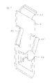
- eine erfindungsgemäße Sicherungsklammer in einer isometrischen Ansicht,
- Fig. 2
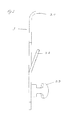
- die erfindungsgemäße Sicherungsklammer in einer Seitenansicht,
- Fig. 3
- die erfindungsgemäße Sicherungsklammer in einer Draufsicht,
- Fig. 4
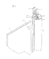
- eine Explosionsdarstellung mit Wandelement, Sicherungsklammer und Hohlprofil,
- Fig. 5
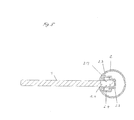
- eine Schnittdarstellung von Wandelement mit Hohlprofil und eingesetzter Sicherungsklammer.
- Fig. 6
- eine weitere Variante der erfindungsgemäßen Sicherungsklammer.
- In den
Fig. 1 bis 5 ist eine Variante einer erfindungsgemäßen Sicherungsklammer 3 dargestellt. Die erfindungsgemäße Sicherungsklammer 3 dient der Sicherung eines rahmenlosen, flächigen Wandelementes 1 aus Glas- oder Kunstglas mit einem vertikalen Hohlprofil 2 mit einem im Hohlprofil 2 angeordneten Halteprofil 2.1 , welches einen Basisbereich 2.2 und zwei Seitenbereiche 2.3, 2.4 umfasst. Das Wandelement 1 ist im oberen Randbereich mit einer Öffnung 1.1 versehen und im Halteprofil 2.1 durch ein klebendes Dichtmittel befestigt und abgedichtet ist. Die Sicherungsklammer 3 ist dabei vorzugsweise an den beiden Seitenbereichen 2.3, 2.4 des Hohlprofils 2 vertikal einklemmbar. Die Klammer 3 ist dazu vorzugsweise aus Federstahl bzw. einem anderen federnden Material gefertigt und besteht aus einem flächigen Gebilde mit einer ersten abgewinkelten Lasche 3.1, die im eingebauten Zustand auf dem oberen Rand eines der Seitenbereiche 2.3, 2.4 des Hohlprofils 2 aufliegt. Weiter sind in vertikaler Richtung auf das Wandelement 1 wirkende Schenkel 3.2, 3.2' sowie eine in Richtung Wandelement 1 horizontal abgewinkelte federnde Lasche 3.3 vorgesehen. Im vorliegenden Beispiel ist die horizontal abgewinkelte federnde Lasche 3.3 pilzkopfartig ausgebildet. Vorteilhaft verhindert diese Geometrie der Lasche dabei, dass das Wandelement aus dem Hohlprofil herausfallen kann. Die horizontal abgewinkelte federnde Lasche 3.3 greift beim Einführen des Wandelementes 1 in das Halteprofil 2.1 des Hohlprofils 2 federnd in die im Wandelement 1 vorgesehene Öffnung 1.1 ein und sichert es. - In der
Fig. 6 wird eine weitere Ausführungsvariante der erfindungsgemäßen Sicherungsklammer gezeigt. Die Klammer 30 besteht aus einem flächigen Gebilde mit drei Abschnitten a, b, c. Der Abschnitt b ist dabei mittig zwischen den Abschnitten a, c angeordnet und weist eine in Richtung Wandelement 1 horizontal abgewinkelte federnde Lasche 34 auf, die analog der der Lasche 3.3 ausgebildet ist. Die horizontal abgewinkelte federnde Lasche 34 greift beim Einführen des Wandelementes 1 in das Halteprofil 2.1 des Hohlprofils 2 federnd in die im Wandelement 1 vorgesehene Öffnung 1.1 ein und sichert es. Die Abschnitte a, c weisen in vertikaler Richtung auf das Wandelement 1 wirkende Schenkel 31, 32, 33 bzw. 31',32', 33' auf. Die beiden Abschnitte a, c sind identisch ausgebildet, aber entgegengesetzt zueinander angeordnet und durch den Abschnitt b voneinander beabstandet. Die vertikal aufgestellten Schenkel führen vorteilhaft zu einem bestimmten Anpressdruck der den Sitz der Sicherung im Profil sicherstellt und eine Lageverschiebung verhindert. Durch die Winkelstellung der horizontal abgewinkelten federnden Lasche 34 entsteht eine schiefe Ebene. Beim Einführen des Wandelementes 1 wird die Lasche 34 in Richtung Seitenbereich des Halteprofils gedrückt. Aufgrund der Federwirkung schnappt die Lasche 34 dann in die im Wandelement 1 vorhandene Öffnung 1.1 ein. Die Geometrie der Lasche 34, die vorzugsweise der Geometrie der Öffnung 1.1 entspricht, verhindert dabei, dass das Wandelement 1 herausfallen kann. Diese anschlagslose Variante einer Sicherungsklammer, kann an jeder beliebigen Position im vertikale Hohlprofil 2 eingesetzt werden.
Claims (6)
- Sicherungsklammer für ein rahmenloses, flächiges Wandelement (1) aus Glas- oder Kunstglas mit einem vertikalen Hohlprofil (2) mit einem im Hohlprofil angeordneten Halteprofil (2.1), welches einen Basisbereich (2.2) und zwei Seitenbereiche (2.3, 2.4) umfasst, wobei das Wandelement (1) im oberen Randbereich mit einer Öffnung (1.1) versehen ist und im Halteprofil (2.1) durch ein klebendes Dichtmittel befestigt und abgedichtet ist, dadurch gekennzeichnet, dass die Sicherungsklammer (3, 30) an wenigstens einem der zwei Seitenbereiche (2.3, 2.4) des Hohlprofils (2) vertikal einklemmbar ist, wobei die Klammer (3, 30) mindestens eine Lasche (3.3, 34) aufweist, die beim Einführen der Wandelementes (1) in das Halteprofil (2.1) des Hohlprofils (2) federnd in die im Wandelement (1) vorgesehene Öffnung (1.1) eingreift und sichert.
- Sicherungsklammer nach Anspruch 1, dadurch gekennzeichnet, dass die Klammer (3) aus einem flächigen Gebilde besteht und- eine erste abgewinkelte Lasche (3.1) aufweist, die im eingebauten Zustand auf dem oberen Rand eines der Seitenbereiche (2.3, 2.4) des Hohlprofils (2) aufliegt,- weiter in vertikaler Richtung auf das Wandelement (1) wirkende Schenkel (3.2, 3.2') sowie- mindestens eine in Richtung Wandelement (1) horizontal abgewinkelte federnde Lasche (3.3) vorgesehen sind.
- Sicherungsklammer nach den Ansprüchen 1 und 2, dadurch gekennzeichnet, dass die horizontal abgewinkelte federnde Lasche (3.3) entsprechend der Geometrie der Öffnung (1.1), vorzugsweise pilzkopfartig ausgebildet ist.
- Sicherungsklammer nach Anspruch 1, dadurch gekennzeichnet, dass- die Klammer (30) aus einem flächigen Gebilde mit drei Abschnitten (a, b, c) besteht,- der Abschnitt (b) mittig zwischen den Abschnitten (a, c) angeordnet ist und mindestens eine in Richtung Wandelement (1) horizontal abgewinkelte federnde Lasche (34) aufweist,- die Abschnitte (a, c) in vertikaler Richtung auf das Wandelement (1) wirkende Schenkel (31, 32, 33, 31'32'33') aufweisen- die Abschnitte (a, c) identisch ausgebildet sind aber entgegengesetzt zueinander angeordnet sind und durch den Abschnitt (b) voneinander beabstandet sind.
- Sicherungsklammer nach Anspruch 4, dadurch gekennzeichnet, dass die horizontal abgewinkelte federnde Lasche (34) entsprechend der Geometrie der Öffnung (1.1), vorzugsweise pilzkopfartig ausgebildet ist.
- Sicherungsklammer nach einem der Ansprüchen 1 bis 5, dadurch gekennzeichnet, dass die Klammer aus Federstahl bzw. einem anderen federnden Material besteht.
Applications Claiming Priority (1)
| Application Number | Priority Date | Filing Date | Title |
|---|---|---|---|
| DE202013001930U DE202013001930U1 (de) | 2013-02-21 | 2013-02-21 | Sicherungsklammer |
Publications (3)
| Publication Number | Publication Date |
|---|---|
| EP2769656A2 true EP2769656A2 (de) | 2014-08-27 |
| EP2769656A3 EP2769656A3 (de) | 2016-08-17 |
| EP2769656B1 EP2769656B1 (de) | 2017-08-23 |
Family
ID=48465182
Family Applications (1)
| Application Number | Title | Priority Date | Filing Date |
|---|---|---|---|
| EP14155863.5A Active EP2769656B1 (de) | 2013-02-21 | 2014-02-20 | Sicherungsklammer |
Country Status (2)
| Country | Link |
|---|---|
| EP (1) | EP2769656B1 (de) |
| DE (1) | DE202013001930U1 (de) |
Family Cites Families (3)
| Publication number | Priority date | Publication date | Assignee | Title |
|---|---|---|---|---|
| DE4119628C1 (en) * | 1991-06-14 | 1992-07-30 | Altura Leiden Holding B.V., Maastricht, Nl | Coupler for profiled rail and shower partition - has securing bracket in duct, adjacent laterally to clamping gap |
| DE19510234C2 (de) | 1995-03-24 | 1999-01-28 | Hueppe Gmbh & Co | Anordnung zum Haltern einer Scheibe, insbesondere einer Glasscheibe in einer Duschabtrennung |
| AT509674B1 (de) * | 2010-04-01 | 2012-04-15 | Hubert Elmer | Halterung für ein rahmenloses, flächiges glaselement |
-
2013
- 2013-02-21 DE DE202013001930U patent/DE202013001930U1/de not_active Expired - Lifetime
-
2014
- 2014-02-20 EP EP14155863.5A patent/EP2769656B1/de active Active
Also Published As
| Publication number | Publication date |
|---|---|
| EP2769656A3 (de) | 2016-08-17 |
| EP2769656B1 (de) | 2017-08-23 |
| DE202013001930U1 (de) | 2013-04-23 |
Similar Documents
| Publication | Publication Date | Title |
|---|---|---|
| EP3496572B1 (de) | Vorrichtung zur befestigung eines vorzugsweise flächigen gegenstandes an einem bauwerk | |
| EP3135850A1 (de) | Bandseitige fingerschutzvorrichtung | |
| DE2059829A1 (de) | Struktursystem fuer den Zusammenbau von vorgefertigten Konstruktionen | |
| DE102008009633B4 (de) | Flächenelement mit mindestens einer Profilrippe | |
| EP3121360B1 (de) | Befestigungssystem für abdeckelemente | |
| EP2769656B1 (de) | Sicherungsklammer | |
| DE102010060672B4 (de) | Fenster- oder Türrahmen | |
| DE102008014189B4 (de) | Steckverbinder | |
| EP3064113B1 (de) | Duschabtrennung | |
| EP3045649B1 (de) | Falzeinlageelement für ein fenster oder eine tür | |
| DE8704077U1 (de) | Abdeckschiene für Kraftfahrzeuge | |
| DE102013105774A1 (de) | Wandbefestigung für Glasscheibe | |
| DE102008016835B4 (de) | Glasfalzeinlage aus Kunststoff | |
| DE202007008150U1 (de) | Befestigungsvorrichtung für Solarmodule | |
| DE102012102497B4 (de) | Verbinder, Werkzeug zur Montage und Verwendung eines Verbinders | |
| DE102016103520B3 (de) | Türzargenanordnung sowie Distanzstück für eine Türzargenanordnung | |
| DE102005047188A1 (de) | Chirurgische Halterung | |
| AT404269B (de) | Vorrichtung zur befestigung von bauelementen | |
| DE8806310U1 (de) | Vorrichtung zur abstandseinstellbaren Befestigung eines Trägers, insbesondere für abgehängte Decken od. dgl., an einem hängend befestigten Tragseil od. dgl. | |
| EP3831257B1 (de) | Anordnung mit einem glassicherungsprofil | |
| EP2818623B1 (de) | Tragkonstruktion für Fassadenelemente | |
| AT511625B1 (de) | Haltevorrichtung | |
| DE29718142U1 (de) | Profilleiste | |
| DE102013015728A1 (de) | Montagehilfe zur Vormontage und Ausrichtung einer Türblende an einer Spülmaschinentür | |
| DE102010014036A1 (de) | Verbindung |
Legal Events
| Date | Code | Title | Description |
|---|---|---|---|
| PUAI | Public reference made under article 153(3) epc to a published international application that has entered the european phase |
Free format text: ORIGINAL CODE: 0009012 |
|
| 17P | Request for examination filed |
Effective date: 20140220 |
|
| AK | Designated contracting states |
Kind code of ref document: A2 Designated state(s): AL AT BE BG CH CY CZ DE DK EE ES FI FR GB GR HR HU IE IS IT LI LT LU LV MC MK MT NL NO PL PT RO RS SE SI SK SM TR |
|
| AX | Request for extension of the european patent |
Extension state: BA ME |
|
| PUAL | Search report despatched |
Free format text: ORIGINAL CODE: 0009013 |
|
| AK | Designated contracting states |
Kind code of ref document: A3 Designated state(s): AL AT BE BG CH CY CZ DE DK EE ES FI FR GB GR HR HU IE IS IT LI LT LU LV MC MK MT NL NO PL PT RO RS SE SI SK SM TR |
|
| AX | Request for extension of the european patent |
Extension state: BA ME |
|
| RIC1 | Information provided on ipc code assigned before grant |
Ipc: E06B 3/54 20060101ALI20160713BHEP Ipc: F16B 5/12 20060101ALI20160713BHEP Ipc: A47K 3/30 20060101AFI20160713BHEP |
|
| R17P | Request for examination filed (corrected) |
Effective date: 20160921 |
|
| RBV | Designated contracting states (corrected) |
Designated state(s): AL AT BE BG CH CY CZ DE DK EE ES FI FR GB GR HR HU IE IS IT LI LT LU LV MC MK MT NL NO PL PT RO RS SE SI SK SM TR |
|
| GRAP | Despatch of communication of intention to grant a patent |
Free format text: ORIGINAL CODE: EPIDOSNIGR1 |
|
| INTG | Intention to grant announced |
Effective date: 20170317 |
|
| GRAS | Grant fee paid |
Free format text: ORIGINAL CODE: EPIDOSNIGR3 |
|
| GRAA | (expected) grant |
Free format text: ORIGINAL CODE: 0009210 |
|
| AK | Designated contracting states |
Kind code of ref document: B1 Designated state(s): AL AT BE BG CH CY CZ DE DK EE ES FI FR GB GR HR HU IE IS IT LI LT LU LV MC MK MT NL NO PL PT RO RS SE SI SK SM TR |
|
| REG | Reference to a national code |
Ref country code: GB Ref legal event code: FG4D Free format text: NOT ENGLISH |
|
| REG | Reference to a national code |
Ref country code: CH Ref legal event code: EP |
|
| REG | Reference to a national code |
Ref country code: AT Ref legal event code: REF Ref document number: 920380 Country of ref document: AT Kind code of ref document: T Effective date: 20170915 |
|
| REG | Reference to a national code |
Ref country code: IE Ref legal event code: FG4D Free format text: LANGUAGE OF EP DOCUMENT: GERMAN |
|
| REG | Reference to a national code |
Ref country code: DE Ref legal event code: R096 Ref document number: 502014005128 Country of ref document: DE |
|
| REG | Reference to a national code |
Ref country code: NL Ref legal event code: MP Effective date: 20170823 |
|
| REG | Reference to a national code |
Ref country code: LT Ref legal event code: MG4D |
|
| PG25 | Lapsed in a contracting state [announced via postgrant information from national office to epo] |
Ref country code: NL Free format text: LAPSE BECAUSE OF FAILURE TO SUBMIT A TRANSLATION OF THE DESCRIPTION OR TO PAY THE FEE WITHIN THE PRESCRIBED TIME-LIMIT Effective date: 20170823 Ref country code: FI Free format text: LAPSE BECAUSE OF FAILURE TO SUBMIT A TRANSLATION OF THE DESCRIPTION OR TO PAY THE FEE WITHIN THE PRESCRIBED TIME-LIMIT Effective date: 20170823 Ref country code: LT Free format text: LAPSE BECAUSE OF FAILURE TO SUBMIT A TRANSLATION OF THE DESCRIPTION OR TO PAY THE FEE WITHIN THE PRESCRIBED TIME-LIMIT Effective date: 20170823 Ref country code: NO Free format text: LAPSE BECAUSE OF FAILURE TO SUBMIT A TRANSLATION OF THE DESCRIPTION OR TO PAY THE FEE WITHIN THE PRESCRIBED TIME-LIMIT Effective date: 20171123 Ref country code: HR Free format text: LAPSE BECAUSE OF FAILURE TO SUBMIT A TRANSLATION OF THE DESCRIPTION OR TO PAY THE FEE WITHIN THE PRESCRIBED TIME-LIMIT Effective date: 20170823 Ref country code: SE Free format text: LAPSE BECAUSE OF FAILURE TO SUBMIT A TRANSLATION OF THE DESCRIPTION OR TO PAY THE FEE WITHIN THE PRESCRIBED TIME-LIMIT Effective date: 20170823 |
|
| PG25 | Lapsed in a contracting state [announced via postgrant information from national office to epo] |
Ref country code: LV Free format text: LAPSE BECAUSE OF FAILURE TO SUBMIT A TRANSLATION OF THE DESCRIPTION OR TO PAY THE FEE WITHIN THE PRESCRIBED TIME-LIMIT Effective date: 20170823 Ref country code: BG Free format text: LAPSE BECAUSE OF FAILURE TO SUBMIT A TRANSLATION OF THE DESCRIPTION OR TO PAY THE FEE WITHIN THE PRESCRIBED TIME-LIMIT Effective date: 20171123 Ref country code: ES Free format text: LAPSE BECAUSE OF FAILURE TO SUBMIT A TRANSLATION OF THE DESCRIPTION OR TO PAY THE FEE WITHIN THE PRESCRIBED TIME-LIMIT Effective date: 20170823 Ref country code: IS Free format text: LAPSE BECAUSE OF FAILURE TO SUBMIT A TRANSLATION OF THE DESCRIPTION OR TO PAY THE FEE WITHIN THE PRESCRIBED TIME-LIMIT Effective date: 20171223 Ref country code: RS Free format text: LAPSE BECAUSE OF FAILURE TO SUBMIT A TRANSLATION OF THE DESCRIPTION OR TO PAY THE FEE WITHIN THE PRESCRIBED TIME-LIMIT Effective date: 20170823 Ref country code: GR Free format text: LAPSE BECAUSE OF FAILURE TO SUBMIT A TRANSLATION OF THE DESCRIPTION OR TO PAY THE FEE WITHIN THE PRESCRIBED TIME-LIMIT Effective date: 20171124 Ref country code: PL Free format text: LAPSE BECAUSE OF FAILURE TO SUBMIT A TRANSLATION OF THE DESCRIPTION OR TO PAY THE FEE WITHIN THE PRESCRIBED TIME-LIMIT Effective date: 20170823 |
|
| PG25 | Lapsed in a contracting state [announced via postgrant information from national office to epo] |
Ref country code: DK Free format text: LAPSE BECAUSE OF FAILURE TO SUBMIT A TRANSLATION OF THE DESCRIPTION OR TO PAY THE FEE WITHIN THE PRESCRIBED TIME-LIMIT Effective date: 20170823 Ref country code: CZ Free format text: LAPSE BECAUSE OF FAILURE TO SUBMIT A TRANSLATION OF THE DESCRIPTION OR TO PAY THE FEE WITHIN THE PRESCRIBED TIME-LIMIT Effective date: 20170823 Ref country code: RO Free format text: LAPSE BECAUSE OF FAILURE TO SUBMIT A TRANSLATION OF THE DESCRIPTION OR TO PAY THE FEE WITHIN THE PRESCRIBED TIME-LIMIT Effective date: 20170823 |
|
| REG | Reference to a national code |
Ref country code: DE Ref legal event code: R097 Ref document number: 502014005128 Country of ref document: DE |
|
| PG25 | Lapsed in a contracting state [announced via postgrant information from national office to epo] |
Ref country code: SK Free format text: LAPSE BECAUSE OF FAILURE TO SUBMIT A TRANSLATION OF THE DESCRIPTION OR TO PAY THE FEE WITHIN THE PRESCRIBED TIME-LIMIT Effective date: 20170823 Ref country code: SM Free format text: LAPSE BECAUSE OF FAILURE TO SUBMIT A TRANSLATION OF THE DESCRIPTION OR TO PAY THE FEE WITHIN THE PRESCRIBED TIME-LIMIT Effective date: 20170823 Ref country code: EE Free format text: LAPSE BECAUSE OF FAILURE TO SUBMIT A TRANSLATION OF THE DESCRIPTION OR TO PAY THE FEE WITHIN THE PRESCRIBED TIME-LIMIT Effective date: 20170823 Ref country code: IT Free format text: LAPSE BECAUSE OF FAILURE TO SUBMIT A TRANSLATION OF THE DESCRIPTION OR TO PAY THE FEE WITHIN THE PRESCRIBED TIME-LIMIT Effective date: 20170823 |
|
| PLBE | No opposition filed within time limit |
Free format text: ORIGINAL CODE: 0009261 |
|
| STAA | Information on the status of an ep patent application or granted ep patent |
Free format text: STATUS: NO OPPOSITION FILED WITHIN TIME LIMIT |
|
| 26N | No opposition filed |
Effective date: 20180524 |
|
| REG | Reference to a national code |
Ref country code: DE Ref legal event code: R082 Ref document number: 502014005128 Country of ref document: DE |
|
| PG25 | Lapsed in a contracting state [announced via postgrant information from national office to epo] |
Ref country code: SI Free format text: LAPSE BECAUSE OF FAILURE TO SUBMIT A TRANSLATION OF THE DESCRIPTION OR TO PAY THE FEE WITHIN THE PRESCRIBED TIME-LIMIT Effective date: 20170823 |
|
| REG | Reference to a national code |
Ref country code: CH Ref legal event code: PL |
|
| PG25 | Lapsed in a contracting state [announced via postgrant information from national office to epo] |
Ref country code: MC Free format text: LAPSE BECAUSE OF FAILURE TO SUBMIT A TRANSLATION OF THE DESCRIPTION OR TO PAY THE FEE WITHIN THE PRESCRIBED TIME-LIMIT Effective date: 20170823 Ref country code: MT Free format text: LAPSE BECAUSE OF FAILURE TO SUBMIT A TRANSLATION OF THE DESCRIPTION OR TO PAY THE FEE WITHIN THE PRESCRIBED TIME-LIMIT Effective date: 20170823 |
|
| GBPC | Gb: european patent ceased through non-payment of renewal fee |
Effective date: 20180220 |
|
| REG | Reference to a national code |
Ref country code: IE Ref legal event code: MM4A |
|
| REG | Reference to a national code |
Ref country code: BE Ref legal event code: MM Effective date: 20180228 |
|
| PG25 | Lapsed in a contracting state [announced via postgrant information from national office to epo] |
Ref country code: LI Free format text: LAPSE BECAUSE OF NON-PAYMENT OF DUE FEES Effective date: 20180228 Ref country code: LU Free format text: LAPSE BECAUSE OF NON-PAYMENT OF DUE FEES Effective date: 20180220 Ref country code: CH Free format text: LAPSE BECAUSE OF NON-PAYMENT OF DUE FEES Effective date: 20180228 |
|
| REG | Reference to a national code |
Ref country code: FR Ref legal event code: ST Effective date: 20181031 |
|
| PG25 | Lapsed in a contracting state [announced via postgrant information from national office to epo] |
Ref country code: IE Free format text: LAPSE BECAUSE OF NON-PAYMENT OF DUE FEES Effective date: 20180220 |
|
| PG25 | Lapsed in a contracting state [announced via postgrant information from national office to epo] |
Ref country code: BE Free format text: LAPSE BECAUSE OF NON-PAYMENT OF DUE FEES Effective date: 20180228 Ref country code: GB Free format text: LAPSE BECAUSE OF NON-PAYMENT OF DUE FEES Effective date: 20180220 Ref country code: FR Free format text: LAPSE BECAUSE OF NON-PAYMENT OF DUE FEES Effective date: 20180228 |
|
| PG25 | Lapsed in a contracting state [announced via postgrant information from national office to epo] |
Ref country code: TR Free format text: LAPSE BECAUSE OF FAILURE TO SUBMIT A TRANSLATION OF THE DESCRIPTION OR TO PAY THE FEE WITHIN THE PRESCRIBED TIME-LIMIT Effective date: 20170823 |
|
| REG | Reference to a national code |
Ref country code: AT Ref legal event code: MM01 Ref document number: 920380 Country of ref document: AT Kind code of ref document: T Effective date: 20190220 |
|
| PG25 | Lapsed in a contracting state [announced via postgrant information from national office to epo] |
Ref country code: AT Free format text: LAPSE BECAUSE OF NON-PAYMENT OF DUE FEES Effective date: 20190220 |
|
| PG25 | Lapsed in a contracting state [announced via postgrant information from national office to epo] |
Ref country code: HU Free format text: LAPSE BECAUSE OF FAILURE TO SUBMIT A TRANSLATION OF THE DESCRIPTION OR TO PAY THE FEE WITHIN THE PRESCRIBED TIME-LIMIT; INVALID AB INITIO Effective date: 20140220 Ref country code: PT Free format text: LAPSE BECAUSE OF FAILURE TO SUBMIT A TRANSLATION OF THE DESCRIPTION OR TO PAY THE FEE WITHIN THE PRESCRIBED TIME-LIMIT Effective date: 20170823 |
|
| PG25 | Lapsed in a contracting state [announced via postgrant information from national office to epo] |
Ref country code: CY Free format text: LAPSE BECAUSE OF FAILURE TO SUBMIT A TRANSLATION OF THE DESCRIPTION OR TO PAY THE FEE WITHIN THE PRESCRIBED TIME-LIMIT Effective date: 20170823 Ref country code: MK Free format text: LAPSE BECAUSE OF NON-PAYMENT OF DUE FEES Effective date: 20170823 |
|
| PG25 | Lapsed in a contracting state [announced via postgrant information from national office to epo] |
Ref country code: AL Free format text: LAPSE BECAUSE OF FAILURE TO SUBMIT A TRANSLATION OF THE DESCRIPTION OR TO PAY THE FEE WITHIN THE PRESCRIBED TIME-LIMIT Effective date: 20170823 |
|
| REG | Reference to a national code |
Ref country code: DE Ref legal event code: R082 Ref document number: 502014005128 Country of ref document: DE Representative=s name: PATENTANWAELTE BRESSEL UND PARTNER MBB, DE |
|
| REG | Reference to a national code |
Ref country code: DE Ref legal event code: R081 Ref document number: 502014005128 Country of ref document: DE Owner name: KERMI DUSCHDESIGN GMBH, DE Free format text: FORMER OWNER: KERMI GMBH, 94447 PLATTLING, DE |
|
| PGFP | Annual fee paid to national office [announced via postgrant information from national office to epo] |
Ref country code: DE Payment date: 20250228 Year of fee payment: 12 |