EP2769434B1 - Hydrogen generator with diaphragm pump - Google Patents
Hydrogen generator with diaphragm pump Download PDFInfo
- Publication number
- EP2769434B1 EP2769434B1 EP12781225.3A EP12781225A EP2769434B1 EP 2769434 B1 EP2769434 B1 EP 2769434B1 EP 12781225 A EP12781225 A EP 12781225A EP 2769434 B1 EP2769434 B1 EP 2769434B1
- Authority
- EP
- European Patent Office
- Prior art keywords
- pump
- hydrogen generator
- liquid
- diaphragm
- disposed
- Prior art date
- Legal status (The legal status is an assumption and is not a legal conclusion. Google has not performed a legal analysis and makes no representation as to the accuracy of the status listed.)
- Not-in-force
Links
- UFHFLCQGNIYNRP-UHFFFAOYSA-N Hydrogen Chemical compound [H][H] UFHFLCQGNIYNRP-UHFFFAOYSA-N 0.000 title claims description 84
- 239000001257 hydrogen Substances 0.000 title claims description 77
- 229910052739 hydrogen Inorganic materials 0.000 title claims description 77
- 239000007788 liquid Substances 0.000 claims description 105
- 239000000446 fuel Substances 0.000 claims description 73
- 238000006243 chemical reaction Methods 0.000 claims description 23
- 239000000376 reactant Substances 0.000 claims description 19
- XLYOFNOQVPJJNP-UHFFFAOYSA-N water Substances O XLYOFNOQVPJJNP-UHFFFAOYSA-N 0.000 claims description 8
- 239000002253 acid Substances 0.000 claims description 4
- 150000004678 hydrides Chemical class 0.000 claims description 4
- 239000003054 catalyst Substances 0.000 claims description 3
- 229920002313 fluoropolymer Polymers 0.000 claims description 3
- 239000004811 fluoropolymer Substances 0.000 claims description 3
- 239000007787 solid Substances 0.000 claims description 3
- 239000000126 substance Substances 0.000 claims description 2
- 239000007789 gas Substances 0.000 description 34
- 238000005086 pumping Methods 0.000 description 13
- 239000000463 material Substances 0.000 description 9
- -1 alcohols Chemical class 0.000 description 7
- 238000004891 communication Methods 0.000 description 6
- 239000003153 chemical reaction reagent Substances 0.000 description 5
- 230000008878 coupling Effects 0.000 description 4
- 238000010168 coupling process Methods 0.000 description 4
- 238000005859 coupling reaction Methods 0.000 description 4
- 229920001971 elastomer Polymers 0.000 description 4
- 229910052751 metal Inorganic materials 0.000 description 4
- 239000002184 metal Substances 0.000 description 4
- 238000000034 method Methods 0.000 description 4
- 239000001301 oxygen Substances 0.000 description 4
- 229910052760 oxygen Inorganic materials 0.000 description 4
- OKKJLVBELUTLKV-UHFFFAOYSA-N Methanol Chemical compound OC OKKJLVBELUTLKV-UHFFFAOYSA-N 0.000 description 3
- 229910052782 aluminium Inorganic materials 0.000 description 3
- XAGFODPZIPBFFR-UHFFFAOYSA-N aluminium Chemical compound [Al] XAGFODPZIPBFFR-UHFFFAOYSA-N 0.000 description 3
- 239000007864 aqueous solution Substances 0.000 description 3
- QVGXLLKOCUKJST-UHFFFAOYSA-N atomic oxygen Chemical compound [O] QVGXLLKOCUKJST-UHFFFAOYSA-N 0.000 description 3
- 239000000806 elastomer Substances 0.000 description 3
- 238000007789 sealing Methods 0.000 description 3
- 229910000033 sodium borohydride Inorganic materials 0.000 description 3
- 239000012279 sodium borohydride Substances 0.000 description 3
- 229920001780 ECTFE Polymers 0.000 description 2
- LFQSCWFLJHTTHZ-UHFFFAOYSA-N Ethanol Chemical compound CCO LFQSCWFLJHTTHZ-UHFFFAOYSA-N 0.000 description 2
- OAKJQQAXSVQMHS-UHFFFAOYSA-N Hydrazine Chemical compound NN OAKJQQAXSVQMHS-UHFFFAOYSA-N 0.000 description 2
- NBIIXXVUZAFLBC-UHFFFAOYSA-N Phosphoric acid Chemical compound OP(O)(O)=O NBIIXXVUZAFLBC-UHFFFAOYSA-N 0.000 description 2
- 239000004696 Poly ether ether ketone Substances 0.000 description 2
- 239000004697 Polyetherimide Substances 0.000 description 2
- 229920004738 ULTEM® Polymers 0.000 description 2
- 230000002378 acidificating effect Effects 0.000 description 2
- 239000011149 active material Substances 0.000 description 2
- 150000001298 alcohols Chemical class 0.000 description 2
- 150000001875 compounds Chemical class 0.000 description 2
- 238000010586 diagram Methods 0.000 description 2
- 230000005611 electricity Effects 0.000 description 2
- 150000002500 ions Chemical class 0.000 description 2
- BDAGIHXWWSANSR-UHFFFAOYSA-N methanoic acid Natural products OC=O BDAGIHXWWSANSR-UHFFFAOYSA-N 0.000 description 2
- 238000012544 monitoring process Methods 0.000 description 2
- 239000004033 plastic Substances 0.000 description 2
- 229920003023 plastic Polymers 0.000 description 2
- 229920002530 polyetherether ketone Polymers 0.000 description 2
- 229920001601 polyetherimide Polymers 0.000 description 2
- 229920000642 polymer Polymers 0.000 description 2
- 229920001343 polytetrafluoroethylene Polymers 0.000 description 2
- 239000004810 polytetrafluoroethylene Substances 0.000 description 2
- 239000002904 solvent Substances 0.000 description 2
- 238000003860 storage Methods 0.000 description 2
- 239000010963 304 stainless steel Substances 0.000 description 1
- 229910000619 316 stainless steel Inorganic materials 0.000 description 1
- OSWFIVFLDKOXQC-UHFFFAOYSA-N 4-(3-methoxyphenyl)aniline Chemical compound COC1=CC=CC(C=2C=CC(N)=CC=2)=C1 OSWFIVFLDKOXQC-UHFFFAOYSA-N 0.000 description 1
- BVKZGUZCCUSVTD-UHFFFAOYSA-L Carbonate Chemical compound [O-]C([O-])=O BVKZGUZCCUSVTD-UHFFFAOYSA-L 0.000 description 1
- 229920007925 Ethylene chlorotrifluoroethylene (ECTFE) Polymers 0.000 description 1
- 229910000589 SAE 304 stainless steel Inorganic materials 0.000 description 1
- KEAYESYHFKHZAL-UHFFFAOYSA-N Sodium Chemical compound [Na] KEAYESYHFKHZAL-UHFFFAOYSA-N 0.000 description 1
- FAPWRFPIFSIZLT-UHFFFAOYSA-M Sodium chloride Chemical compound [Na+].[Cl-] FAPWRFPIFSIZLT-UHFFFAOYSA-M 0.000 description 1
- 230000009471 action Effects 0.000 description 1
- AZDRQVAHHNSJOQ-UHFFFAOYSA-N alumane Chemical compound [AlH3] AZDRQVAHHNSJOQ-UHFFFAOYSA-N 0.000 description 1
- 229910000147 aluminium phosphate Inorganic materials 0.000 description 1
- 230000001174 ascending effect Effects 0.000 description 1
- JBANFLSTOJPTFW-UHFFFAOYSA-N azane;boron Chemical compound [B].N JBANFLSTOJPTFW-UHFFFAOYSA-N 0.000 description 1
- 150000001642 boronic acid derivatives Chemical class 0.000 description 1
- 238000004132 cross linking Methods 0.000 description 1
- 238000013461 design Methods 0.000 description 1
- 230000006866 deterioration Effects 0.000 description 1
- 239000003792 electrolyte Substances 0.000 description 1
- 238000005265 energy consumption Methods 0.000 description 1
- 235000019253 formic acid Nutrition 0.000 description 1
- 229930195733 hydrocarbon Natural products 0.000 description 1
- 150000002430 hydrocarbons Chemical class 0.000 description 1
- 125000004435 hydrogen atom Chemical group [H]* 0.000 description 1
- 230000010354 integration Effects 0.000 description 1
- 239000012280 lithium aluminium hydride Substances 0.000 description 1
- SIAPCJWMELPYOE-UHFFFAOYSA-N lithium hydride Chemical compound [LiH] SIAPCJWMELPYOE-UHFFFAOYSA-N 0.000 description 1
- 229910000103 lithium hydride Inorganic materials 0.000 description 1
- 238000004519 manufacturing process Methods 0.000 description 1
- 239000012528 membrane Substances 0.000 description 1
- 229910052987 metal hydride Inorganic materials 0.000 description 1
- 150000004681 metal hydrides Chemical class 0.000 description 1
- 150000002739 metals Chemical class 0.000 description 1
- 150000007524 organic acids Chemical class 0.000 description 1
- 235000005985 organic acids Nutrition 0.000 description 1
- 239000007800 oxidant agent Substances 0.000 description 1
- 230000001590 oxidative effect Effects 0.000 description 1
- 239000010702 perfluoropolyether Substances 0.000 description 1
- 230000002093 peripheral effect Effects 0.000 description 1
- 230000002572 peristaltic effect Effects 0.000 description 1
- 229960004838 phosphoric acid Drugs 0.000 description 1
- 235000011007 phosphoric acid Nutrition 0.000 description 1
- 229920001296 polysiloxane Polymers 0.000 description 1
- 230000037452 priming Effects 0.000 description 1
- 230000008569 process Effects 0.000 description 1
- 230000004044 response Effects 0.000 description 1
- 230000002441 reversible effect Effects 0.000 description 1
- 239000011780 sodium chloride Substances 0.000 description 1
- 229910000104 sodium hydride Inorganic materials 0.000 description 1
- 239000012312 sodium hydride Substances 0.000 description 1
- NVIFVTYDZMXWGX-UHFFFAOYSA-N sodium metaborate Chemical compound [Na+].[O-]B=O NVIFVTYDZMXWGX-UHFFFAOYSA-N 0.000 description 1
- 239000008247 solid mixture Substances 0.000 description 1
- 239000000243 solution Substances 0.000 description 1
- 229910001220 stainless steel Inorganic materials 0.000 description 1
- 229920001169 thermoplastic Polymers 0.000 description 1
- 239000004416 thermosoftening plastic Substances 0.000 description 1
- 238000012546 transfer Methods 0.000 description 1
- 229910000045 transition metal hydride Inorganic materials 0.000 description 1
Images

Classifications
-
- H—ELECTRICITY
- H01—ELECTRIC ELEMENTS
- H01M—PROCESSES OR MEANS, e.g. BATTERIES, FOR THE DIRECT CONVERSION OF CHEMICAL ENERGY INTO ELECTRICAL ENERGY
- H01M8/00—Fuel cells; Manufacture thereof
- H01M8/06—Combination of fuel cells with means for production of reactants or for treatment of residues
- H01M8/0606—Combination of fuel cells with means for production of reactants or for treatment of residues with means for production of gaseous reactants
-
- C—CHEMISTRY; METALLURGY
- C01—INORGANIC CHEMISTRY
- C01B—NON-METALLIC ELEMENTS; COMPOUNDS THEREOF; METALLOIDS OR COMPOUNDS THEREOF NOT COVERED BY SUBCLASS C01C
- C01B3/00—Hydrogen; Gaseous mixtures containing hydrogen; Separation of hydrogen from mixtures containing it; Purification of hydrogen
- C01B3/02—Production of hydrogen or of gaseous mixtures containing a substantial proportion of hydrogen
- C01B3/06—Production of hydrogen or of gaseous mixtures containing a substantial proportion of hydrogen by reaction of inorganic compounds containing electro-positively bound hydrogen, e.g. water, acids, bases, ammonia, with inorganic reducing agents
- C01B3/065—Production of hydrogen or of gaseous mixtures containing a substantial proportion of hydrogen by reaction of inorganic compounds containing electro-positively bound hydrogen, e.g. water, acids, bases, ammonia, with inorganic reducing agents from a hydride
-
- H—ELECTRICITY
- H01—ELECTRIC ELEMENTS
- H01M—PROCESSES OR MEANS, e.g. BATTERIES, FOR THE DIRECT CONVERSION OF CHEMICAL ENERGY INTO ELECTRICAL ENERGY
- H01M8/00—Fuel cells; Manufacture thereof
- H01M8/06—Combination of fuel cells with means for production of reactants or for treatment of residues
- H01M8/0606—Combination of fuel cells with means for production of reactants or for treatment of residues with means for production of gaseous reactants
- H01M8/065—Combination of fuel cells with means for production of reactants or for treatment of residues with means for production of gaseous reactants by dissolution of metals or alloys; by dehydriding metallic substances
-
- Y—GENERAL TAGGING OF NEW TECHNOLOGICAL DEVELOPMENTS; GENERAL TAGGING OF CROSS-SECTIONAL TECHNOLOGIES SPANNING OVER SEVERAL SECTIONS OF THE IPC; TECHNICAL SUBJECTS COVERED BY FORMER USPC CROSS-REFERENCE ART COLLECTIONS [XRACs] AND DIGESTS
- Y02—TECHNOLOGIES OR APPLICATIONS FOR MITIGATION OR ADAPTATION AGAINST CLIMATE CHANGE
- Y02E—REDUCTION OF GREENHOUSE GAS [GHG] EMISSIONS, RELATED TO ENERGY GENERATION, TRANSMISSION OR DISTRIBUTION
- Y02E60/00—Enabling technologies; Technologies with a potential or indirect contribution to GHG emissions mitigation
- Y02E60/30—Hydrogen technology
- Y02E60/36—Hydrogen production from non-carbon containing sources, e.g. by water electrolysis
-
- Y—GENERAL TAGGING OF NEW TECHNOLOGICAL DEVELOPMENTS; GENERAL TAGGING OF CROSS-SECTIONAL TECHNOLOGIES SPANNING OVER SEVERAL SECTIONS OF THE IPC; TECHNICAL SUBJECTS COVERED BY FORMER USPC CROSS-REFERENCE ART COLLECTIONS [XRACs] AND DIGESTS
- Y02—TECHNOLOGIES OR APPLICATIONS FOR MITIGATION OR ADAPTATION AGAINST CLIMATE CHANGE
- Y02E—REDUCTION OF GREENHOUSE GAS [GHG] EMISSIONS, RELATED TO ENERGY GENERATION, TRANSMISSION OR DISTRIBUTION
- Y02E60/00—Enabling technologies; Technologies with a potential or indirect contribution to GHG emissions mitigation
- Y02E60/30—Hydrogen technology
- Y02E60/50—Fuel cells
Definitions
- This invention relates to a hydrogen generator with a pump for pumping liquid reactant, and to a fuel cell system including the hydrogen generator.
- a fuel cell is an electrochemical cell that uses materials from outside the cell as the active materials for the positive and negative electrode. Because a fuel cell does not have to contain all of the active materials used to generate electricity, the fuel cell can be made with a small volume relative to the amount of electrical energy produced compared to other types of batteries.
- fuel cells There are several types of fuel cells, which can be classified in various ways.
- fuel cells can be categorized according to the type of electrolyte used, typically one of five types: proton exchange membrane fuel cell (PEMFC), alkaline fuel cell (AFC), phosphoric-acid fuel cell (PAFC), solid oxide fuel cell (SOFC) and molten carbonate fuel cell (MCFC).
- PEMFC proton exchange membrane fuel cell
- AFC alkaline fuel cell
- PAFC phosphoric-acid fuel cell
- SOFC solid oxide fuel cell
- MCFC molten carbonate fuel cell
- Each of these types of fuel cell uses hydrogen and oxygen. Hydrogen is oxidized at the negative electrode, and oxygen is reduced at the positive electrode. Ions pass through an electrically nonconductive, ion permeable separator and electrons pass through an external circuit to provide an electric current.
- hydrogen is formed from a hydrogen-containing fuel supplied to the negative electrode side of the fuel cell.
- hydrogen gas is supplied to the fuel cell from a source outside the fuel cell.
- a fuel cell system can include a fuel cell battery, including one or more fuel cells (a fuel cell stack), and a gas source, such as a gas tank or a gas generator.
- Gas generators that supply gas to a fuel cell can be an integral part of a fuel cell system, or they can be removably coupled to the fuel cell system.
- a removable gas generator can be replaced with another one when the gas producing reactants have been consumed.
- Removable gas generators can be disposable (intended for only a one-time use) or refillable (intended for use multiple times) to replace consumed reactant materials.
- the coupling between the gas generator and the rest of the fuel cell system can include one or more valves.
- the valve(s) can be opened and closed manually, valve operation can be controlled by a control system, or the valve(s) can be opened and closed by an actuator that is operated by making or separating components of the coupling.
- the latter method can be used in quick disconnect couplings, for example, where the valve is opened when the gas generator is coupled to the rest of the system and closed when the gas generator is uncoupled.
- Gas generators can use a variety of types of reactants to produce the gas.
- at least one reactant is stored in a reservoir as a liquid, and the liquid is transferred from the reservoir to a reaction chamber, where it reacts to produce the desired gas.
- Various means have been used to transfer the liquid, including gravitational flow, application of pressure to the liquid, wicking the liquid by capillary action, and pumping with a mechanical pump. Each method has advantages and disadvantages.
- Pumping the liquid can be advantageous because the pumping can be started and stopped, so gas is produced on an as-needed basis.
- a pump can also provide the liquid at a controlled rate.
- many factors can be considered, such as compatibility of the pump materials and components with the liquid being pumped, the ability of the pump to withstand the environment in which it is to be used (e.g., temperature and pressure), the size of the pump, the pumping rate, rate control (accuracy and precision), the amount and type of power required to operate the pump, integration of the pump into the gas generator or the system, compatibility of the pump with the method of controlling the production of gas, the reliability of the pump, and the amount of heat and noise produced by the pump during operation.
- an object of the present invention is to provide a pump that is suitable for pumping liquid reactant in a gas generator and a fuel cell system including the pump, particularly a fuel cell system that can be used to power portable consumer electronic devices such as communications equipment, portable computers and video games.
- US 2009/0104481 describes a hydrogen generator comprising a reaction chamber and a liquid reagent storage chamber.
- a liquid reagent conduit and a liquid reagent regulator allow the liquid reagent to be transported from the liquid reagent storage chamber to the reaction chamber.
- the regulator may be a pump or a valve, including a diaphragm pump.
- US 2004/0009392 , EP 1375419 , WO 2007/120757 , US 2003/0070938 and US 4613304 also describe hydrogen generators.
- JP 2002/257050 describes a diaphragm pump.
- a pump as described below, a hydrogen generator including the pump and a fuel cell system including the hydrogen generator.
- one aspect of the present invention is a hydrogen generator including a housing, a liquid reservoir containing a liquid reactant and disposed within the housing, a reaction area disposed within the housing, and a pump configured to pump the liquid reactant from the liquid reservoir, through a liquid flow path to the reaction area, where the liquid is capable of reacting within the reaction area to evolve hydrogen gas.
- the pump is a diaphragm pump and includes a pump chamber having a volume; a first diaphragm defining a portion of the pump chamber; a liquid inlet path to the pump chamber with an inlet valve disposed therein, the inlet valve biased against a second diaphragm in a closed position; a liquid outlet path from the pump chamber with an outlet valve disposed therein, the outlet valve biased against a third diaphragm in a closed position; a motor with a rotatable shaft; a first cam, a second cam and a third cam, all disposed on the rotatable shaft; a first pushrod in contact with the first cam and configured to cooperate with the first cam to reversibly displace the first diaphragm to reduce the pump chamber volume; a second pushrod in contact with the second cam and configured to cooperate with the second cam to reversibly displace the second diaphragm to open the inlet valve; and a third pushrod in contact with the third cam and configured to cooperate with the third
- a second aspect of the invention is a fuel cell system including the pump and a fuel cell stack.
- the operation of the pump can be controlled based on a rate of hydrogen evolution required for the fuel cell stack.
- the pump described below is compatible with a variety of liquid reactants for various types of gas generators, including water, acidic and basic aqueous solutions, hydrogen-containing hydrocarbons such as alcohols, and nonaqueous liquids such as hydrazine, depending on the specific materials selected.
- the pump can be sized to pump liquids at rates over a broad range, can be easily started and stopped, and can pump liquid in either direction, based on the direction in which the pump motor turns.
- the pump can withstand temperatures, depending on the specific materials selected.
- the pump will operate quietly so it is not a distraction to the user of the device being powered by the fuel cell system.
- the pump also has a simple design and low cost.
- a pump according to the invention is a motor-driven diaphragm pump with mechanically operated valves.
- Mechanically operated valves are advantageous because they are positively closed (e.g., by springs), so there is no free flow of liquid in either direction when the valves are closed, even with internal or external overpressure; in fact external overpressure (e.g., from a gas generator) will tend to close the valves even tighter. Because pressure-responsive check valves are not used, the pump is more capable of self-priming at startup.
- the pump is a diaphragm pump with mechanically operated valves, it is not necessary to pinch off rubber tubing to prevent the free flow of liquid like in a peristaltic pump, in which the tubing can deteriorate more quickly.
- the diaphragm pump with mechanically operated valves also operates quietly.
- the pump chamber is sized to allow the pump to provide liquid at the desired maximum rate.
- the pumping diaphragm and the valves are displaced by cam-driven pushrods.
- the pushrods that operate the valves are isolated from the valves by sealing diaphragms so the pushrods do not come in contact with the liquid being pumped, thereby protecting them from the liquid, extending the useful life of the pump, and making more alternative and/or less expensive materials feasible.
- a pump capable of pumping 1 to 5 cm 3 of liquid per minute may be desired.
- a pump operating at 60 cycles per minute this would require a pump chamber with a volume of 0.015 to 0.085 cm 3 .
- Fuel cell systems with larger pumps may be too large for equipment that is intended to be carried by the user. Fuel cell systems requiring smaller pumps may not have fuel cell stacks capable of both powering an electronic device as well as the pump motor. In some embodiments the pump can have a maximum operating speed of about 100 cycles per minute.
- the motor can be an electric motor, operating on either alternating or direct current.
- the motor can be powered by a fuel cell stack in the fuel cell system or by another electrical power source in the fuel cell system, the electronic device being by the fuel cell system, or a power source external to the fuel cell system and the electronic device. If desired, the motor and the pump can be reversible. This can be advantageous for more rapidly stopping the flow of liquid, and the resultant generation of gas, for example.
- the pump can include a frame that supports the motor, camshaft and other components.
- the motor rotates the camshaft, which includes three cams, one to lift a pushrod that displaces the pumping diaphragm into the pump chamber, one to lift a pushrod that displaces a seal diaphragm to open an inlet valve, and the other one to lift a pushrod that displaces a seal diaphragm to open an outlet valve.
- the pumping diaphragm biases the pushrod against the corresponding cam, and the other pushrods are biased against their corresponding cams by the seal diaphragms and valves, each valve diaphragm being biased against its corresponding seal diaphragm, by a valve spring for example.
- the pump includes a liquid inlet path through which liquid can flow to the pump chamber and a liquid outlet path through with liquid can flow from the pump chamber.
- the inlet valve is disposed such that the liquid inlet path is closed when the inlet valve is in the closed position, and the outlet valve is disposed such that the liquid outlet path is closed when the outlet valve is in the closed position.
- the pump chamber can be disposed in a pump body mounted on the pump frame.
- the pump chamber can be a cavity that can fill with liquid when the pump is in the intake portion of a cycle and into which the pump diaphragm is pushed to force the liquid out of the pump chamber during the discharge portion of the cycle.
- the volume of the pump chamber is defined by the walls of the cavity and the pump diaphragm.
- the pump body can also include through-holes in which the inlet and outlet valves are disposed, as well as openings between the through-holes and the pump chamber through which the liquid can flow when the valves are open.
- the pump After the liquid is discharged from the pump chamber, the pump enters the intake portion of the cycle, in which the outlet valve is closed, the pump diaphragm is displaced into the pump chamber, the inlet valve is opened, and then the pump diaphragm is allowed to retract from the pump chamber, creating a partial vacuum to facilitate the flow of liquid through the liquid inlet path and into the pump chamber.
- the pump At the end of the intake portion of the cycle the pump returns to the parked position, ready to begin the next cycle.
- the peripheral edges of the pump diaphragm and the seal diaphragms can be pressed between the frame and the pump body to retain them in position and provide liquid seals.
- the diaphragms can be separate components, or they can be separate sections of a single diaphragm component.
- the pump can include connectors to provide an external connection between a liquid reservoir and the liquid inlet path and between the liquid outlet path and a reaction chamber.
- the pump can include other components such as one or more valve covers, seals, fasteners, and so on.
- a sensor can be added to detect when the pump is in a particular position, such as bottom dead center, which can be the parked position, as described below.
- the sensor can sense any of a variety of pump features in a desired position.
- a magnet can be added to the camshaft so the sensor will detect the magnet when it is in the desired position.
- a sensor can be used for a number of purposes. For example, a sensor can be used to indicate that the pump is moving as intended, or it can be used as part of a control system to stop the pump in a desired position (e.g., the parked position).
- thermoplastics such as polyether ether ketone (PEEK) and polyetherimide (PEI) (e.g., ULTEM® PEI from SABIC Americas, Inc.)
- PEEK polyether ether ketone
- PEI polyetherimide
- heat and solvent resistant elastomers e.g., elastomers including a crosslinked fluoropolymer, such as SIFEL® from Shin-Etsu Chemical Co., which has a perfluoropolyether backbone with a terminal silicone crosslinking group
- low friction, high strength, heat resistant polymers such as polytetrafluoroethylene (PTFE) and ethylene-chlorotrifluoroethylene (ECTFE) based polymers (e.g., TURCITE® materials from Trelleborg Sealing Solutions) and bearing grade plastics (e.g., IGLIDE® from IGUS®) can be suitable for valve lifters, cam
- FIG. 4 is an exploded view of an embodiment of a pump. It includes a frame 110 with an end 112 that can be mounted to the frame 110 with screws 116 (only one screw is shown).
- the motor 114 can be mounted onto the frame 110 with screws 116 (only one screw is shown).
- a camshaft 118 can be mounted to the motor 114 and to the frame end 112 with a shaft 120 and a bearing 122.
- the camshaft 118 has three cams 124A, 124B and 124C that raise pushrods 126A, 126B and 126C as the camshaft 118 is rotated by the motor 114.
- a pump diaphragm 128A and two seal diaphragms 128B and 128C are disposed between the top of the frame 110 and the bottom of a pump body 130.
- the diaphragms 128A, 128B and 128C can be separate component or can be formed in a single diaphragm sheet 128.
- the diaphragms 128A, 128B and 128C isolate the pushrods 126A, 126B and 126C from liquid within the pump body 130.
- the pump body 130 has a central recess (not shown) in its bottom surface that serves as the pump chamber 132 ( FIGS. 1 , 2 and 3 ) and through-holes 134 within which an inlet valve 136 and an outlet valve 138 are disposed.
- Each of the through-holes 134 has a lower annular lip as a valve seat, and seals 140 on the valves 136 and 138 seal against the valve seats when the valves 136 and 138 are closed.
- the valves 136 and 138 are biased against the seal diaphragms 128B and 128C by springs 142, which can be disposed between the tops of the valves 136 and 138 and the inside surface of a valve cover 144.
- O-rings 146 around the through-holes 134 in the pump body 130 provide a seal between the pump body 130 and the valve cover 144.
- the valve cover 144 is secured to the pump body 130 with screws 148 (only one shown).
- Connectors 150 provide a sealing connection between the liquid reservoir (not shown) and the liquid inlet path to the pump chamber 130 and between the liquid outlet path from the pump chamber 130 and the gas generator (not shown).
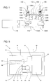
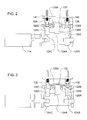
- FIGS. 1 , 2 and 3 are cross sectional drawings of the pump shown in FIG. 4 (as viewed from the rear as oriented in FIG. 4 ), with the pump in various positions.
- the pump In FIG. 1 the pump is in the parked position. In the parked position the pushrods 126A, 126B and 126C are all in the full down position so that the inlet valve 136 and outlet valve 138 are both closed, and the volume of the pump chamber 132 is at its maximum. In this position the diaphragms 128A, 128B and 128C are in or close to a relaxed state, in order to minimize deterioration, and liquid is not able to flow into or out of the pump. The pump moves from the parked position to the discharge portion of a cycle. In FIG.
- the pump is in the discharge portion of a cycle.
- pushrod 126C and seal diaphragm 128C are raised, opening the outlet valve 138, and the pump pushrod 126A and pump diaphragm 128A are raised, forcing liquid from the pump chamber 138 and out through the liquid outlet path.
- the pump is in the discharge portion of a cycle, with the outlet valve 138 open and the pump diaphragm 128A ascending.
- the pump begins the intake portion of the cycle ( FIG. 3 ).
- the pump cam 124B raises pushrod 126B and seal diaphragm 128B to open inlet valve 136 and allow liquid to flow in through the liquid inlet path to the pump chamber 132.
- Pump cam 124A and pump diaphragm 128A then lower, to draw liquid into the pump chamber 132.
- the inlet valve 136 is fully open and the pump diaphragm 128A is descending.
- the pump is again in the parked position ( FIG. 1 ).
- the pump diaphragm 128A is in its lowest position, the pump chamber 132 is filled with liquid, and the inlet valve 136 and outlet valve 138 are both closed.
- the pump can be used to pump liquid from a reservoir to a reaction area in a gas generator, such as a hydrogen generator that provides hydrogen gas to a fuel cell stack.
- a gas generator such as a hydrogen generator that provides hydrogen gas to a fuel cell stack.
- the hydrogen generator and fuel cell stack are part of a fuel cell system that can be used to provide electric power to an electronic device.
- the hydrogen generator can use a variety of reactants and types of reactions.
- At least one reactant is a hydrogen-containing compound.
- Hydrogen containing compounds include hydrides such as metal hydrides (e.g., sodium hydride, lithium hydride, lithium aluminum hydride), transition metal hydrides (e.g., aluminum hydride), organic (saline or ionic) hydrides (e.g., C 6 H 5 C(O)CH 3 ), borohydrides (e.g., sodium borohydride, ammonia borane), borates (e.g., sodium metaborate), alcohols (e.g., methanol, ethanol), organic acids (e.g., formic acid), and water.
- At least one reactant is a liquid or is contained in a liquid that is stored in a reservoir within the hydrogen generator.
- a catalyst can be used to catalyze the hydrogen-generation reactions within the reaction area.
- the pump can be located within or outside the hydrogen generator housing. If it is within the housing, fewer connections are needed between the housing and the remainder of the fuel cell system, but if the hydrogen generator is not reusable (e.g., by recharging it with fresh reactants), the cost of hydrogen generation is increased. For disposable hydrogen generators, it is generally desirable to locate the pump outside the hydrogen generator, where it can be used many times.
- the pump can be used to control the supply of liquid to the reaction area (and the rate of hydrogen generation). For example, the pump can be operated continuously or intermittently so hydrogen is produced only as needed. Need can be determined based on one or more device characteristics (e.g., on/off, operating mode, rate of energy consumption, internal battery condition), fuel cell characteristics (e.g., voltage, amperage, power output, hydrogen gas pressure, temperature), hydrogen generator characteristics (e.g., hydrogen gas pressure, temperature), or a combination thereof.
- a control system can be included in the device and/or the fuel cell system for monitoring these characteristics and controlling the operation of the pump (e.g., by turning the motor on and off or by adjusting the motor speed).
- FIG. 5 is a schematic diagram of an embodiment of a fuel cell system. Not all components are essential, and components of the fuel cell system are not necessarily - disposed as shown in FIG. 1 (e.g., some components may be located within an apparatus powered by the fuel cell system).
- Fuel cell system 10 includes a fuel cell stack 12 and a removable hydrogen generator 14 for providing hydrogen fuel to the stack 12. The hydrogen passes through an outlet valve 16 in the hydrogen generator 14, and through an inlet 24 to the stack 12, where it is used as a fuel by the anode. Another gas, such as oxygen, enters the stack 12 through an inlet 26, where it is used as oxidant by the cathode. The stack 12 produces electricity that is provided to an electric apparatus through a power output 28.
- Reactants within the hydrogen generator 14 react to produce the hydrogen.
- a liquid in the hydrogen generator 14 is transferred from a reservoir to a reactant area where the hydrogen is generated.
- the liquid is transferred by a pump 22, which can be disposed within or outside the hydrogen generator housing. If the pump 22 is within the housing, fewer external connections are needed, but if the pump 22 is an external pump, it can continue to be used after the used hydrogen generator 14 is replaced. In FIG. 5 the pump 22 is shown outside the hydrogen generator 14.
- the liquid can be pumped out of the hydrogen generator 14 through an outlet valve 18 and back into the hydrogen generator 14 through an inlet valve 20.
- the fuel cell system 10 can include an optional control system for controlling the operation of the gas generator 14 and/or the fuel cell stack 12.
- Components of the control system can be disposed in the hydrogen generator 14, the fuel cell stack 12, the apparatus powered by the fuel cell system, or a combination thereof.
- the control system can include a controller 30. Although the controller 30 can be located within the fuel cell system 10, as shown in FIG. 5 , it can be elsewhere in the fuel cell system 10 or within the electric apparatus for example.
- the controller 30 can communicate through a communication line 32 with the pump 22, through a communication line 34 with the stack 12, through a communication line 36 with the hydrogen generator 14, and/or through a communication line 38 with the device. Sensors for monitoring voltage, current, temperature, pressure and other parameters can be disposed in or in communication with those components so gas generation can be controlled based on those parameters.
- a pump was manufactured according to the embodiment shown in FIG. 4 for pumping water and acidic aqueous solutions.
- a 5 volt direct current motor and a machined aluminum camshaft were mounted onto a machined aluminum frame.
- Machined TURCITE® pushrods and a molded SIFEL® diaphragm sheet were used.
- the pump body was machined from a block of ULTEM®.
- the valve springs were made from 316 stainless steel, and the valve cover was 304 stainless steel.
- the maximum volume of the pump chamber in the pump body was 0.06 cm 3 with the pump in the parked position.
- the pump was able to deliver 0.04 cm 3 /cycle with the pump operating at 66 cycles/minute.
- the pump was also able to generate a suction of 3 psi (211 g/cm 2 ), to draw liquid from the reservoir for priming, and 8 psi (562 g/cm 2 ) of discharge pressure.
- the pump from Example 1 was used with a hydrogen generator.
- the hydrogen generator included a liquid reservoir containing water within a housing.
- the pump was located outside the hydrogen generator, with a liquid feed line extending from the reservoir, through an outlet in the housing, to the pump, and a liquid supply line extending from the pump, through an inlet in the housing to a reaction area containing a solid mixture of sodium borohydride and acid. Water pumped to the reaction area reacted with the sodium borohydride in the presence of the acid to produce hydrogen gas.
- the hydrogen gas was supplied as the fuel to a hydrogen-oxygen fuel cell stack.
- a pump according to the invention is suitable for pumping liquid for a hydrogen generator, it may also be suitable for use in other applications.
Landscapes
- Chemical & Material Sciences (AREA)
- Engineering & Computer Science (AREA)
- Chemical Kinetics & Catalysis (AREA)
- Life Sciences & Earth Sciences (AREA)
- Organic Chemistry (AREA)
- Manufacturing & Machinery (AREA)
- Sustainable Development (AREA)
- Sustainable Energy (AREA)
- Electrochemistry (AREA)
- General Chemical & Material Sciences (AREA)
- General Health & Medical Sciences (AREA)
- Combustion & Propulsion (AREA)
- Inorganic Chemistry (AREA)
- Health & Medical Sciences (AREA)
- Fuel Cell (AREA)
- Reciprocating Pumps (AREA)
Applications Claiming Priority (2)
| Application Number | Priority Date | Filing Date | Title |
|---|---|---|---|
| US13/278,594 US8545195B2 (en) | 2011-10-21 | 2011-10-21 | Hydrogen generator with pump |
| PCT/US2012/060475 WO2013059220A1 (en) | 2011-10-21 | 2012-10-17 | Hydrogen generator with diaphragm pump |
Publications (2)
| Publication Number | Publication Date |
|---|---|
| EP2769434A1 EP2769434A1 (en) | 2014-08-27 |
| EP2769434B1 true EP2769434B1 (en) | 2016-01-06 |
Family
ID=47138177
Family Applications (1)
| Application Number | Title | Priority Date | Filing Date |
|---|---|---|---|
| EP12781225.3A Not-in-force EP2769434B1 (en) | 2011-10-21 | 2012-10-17 | Hydrogen generator with diaphragm pump |
Country Status (5)
| Country | Link |
|---|---|
| US (1) | US8545195B2 (OSRAM) |
| EP (1) | EP2769434B1 (OSRAM) |
| JP (1) | JP2014532824A (OSRAM) |
| CN (1) | CN104040774A (OSRAM) |
| WO (1) | WO2013059220A1 (OSRAM) |
Families Citing this family (7)
| Publication number | Priority date | Publication date | Assignee | Title |
|---|---|---|---|---|
| US20140193735A1 (en) * | 2013-01-04 | 2014-07-10 | Lilliputian Systems, Inc. | Low Vibration Linear Motor Systems |
| US9765713B2 (en) * | 2014-07-11 | 2017-09-19 | Huan-Hsin Kou | Hydrogen fuel assist device for an internal combustion engine system |
| CN106955805B (zh) * | 2016-01-08 | 2020-04-28 | 深圳市华匠技术有限公司 | 隔膜泵水枪 |
| CA3056915A1 (en) * | 2016-03-18 | 2017-09-21 | Deka Products Limited Partnership | Pressure control gaskets for operating pump cassette membranes |
| CA3067841A1 (en) | 2017-07-06 | 2019-01-10 | Quasuras, Inc. | Medical pump with flow control |
| US20220170452A1 (en) * | 2019-08-13 | 2022-06-02 | Hewlett-Packard Development Company, L.P. | Fluid ejection apparatus for discreet packet transfer of fluid |
| US20210170095A1 (en) | 2019-12-06 | 2021-06-10 | Quasuras, Inc. | Rotary microfluidic medical pump |
Family Cites Families (23)
| Publication number | Priority date | Publication date | Assignee | Title |
|---|---|---|---|---|
| SE380445B (sv) | 1973-11-23 | 1975-11-10 | Bjoerklund K B | Forfarande for intermittent dosering av sma volymer samt anordning for genomforande av forfarandet |
| US4236880A (en) * | 1979-03-09 | 1980-12-02 | Archibald Development Labs, Inc. | Nonpulsating IV pump and disposable pump chamber |
| US4613304A (en) | 1982-10-21 | 1986-09-23 | Meyer Stanley A | Gas electrical hydrogen generator |
| JPS63192447A (ja) * | 1987-10-02 | 1988-08-09 | ミネソタ マイニング アンド マニュファクチュアリング カンパニー | 非脉動ivポンプ |
| US6280867B1 (en) | 1997-12-05 | 2001-08-28 | Griff Consulting, Inc. | Apparatus for pumping a fluid in a fuel cell system |
| JP2002257050A (ja) | 2001-03-02 | 2002-09-11 | Nikkiso Co Ltd | ダイアフラムポンプ |
| CA2347646A1 (en) | 2001-05-07 | 2002-11-07 | Mohammed Mali | Hydrogen generation |
| US7691527B2 (en) | 2002-04-24 | 2010-04-06 | Petillo Phillip J | Method and apparatus for generating hydrogen |
| US7097813B2 (en) | 2002-06-21 | 2006-08-29 | Hewlett-Packard Development Company, L.P. | Hydrogen generating apparatus |
| JP2005273865A (ja) * | 2004-03-26 | 2005-10-06 | Shimadzu Corp | 弁とそれを用いた送液ポンプ |
| JP2006114398A (ja) | 2004-10-15 | 2006-04-27 | Mikuni Corp | 燃料電池システム |
| US7537437B2 (en) | 2004-11-30 | 2009-05-26 | Nidec Sankyo Corporation | Linear actuator, and valve device and pump device using the same |
| US20090148321A1 (en) | 2004-11-30 | 2009-06-11 | Nidec Sankyo Corporation | Pump device and fuel cell |
| US20070011251A1 (en) | 2004-12-09 | 2007-01-11 | Mcnamara Kevin W | Fuel cartridge for fuel cell power systems and methods for power generation |
| US8187758B2 (en) | 2005-08-11 | 2012-05-29 | Ardica Technologies Inc. | Fuel cell apparatus with a split pump |
| US8795926B2 (en) | 2005-08-11 | 2014-08-05 | Intelligent Energy Limited | Pump assembly for a fuel cell system |
| JP2007239737A (ja) | 2006-02-13 | 2007-09-20 | Nidec Sankyo Corp | ミキシングポンプ装置および燃料電池 |
| US20070271844A1 (en) | 2006-04-12 | 2007-11-29 | Mohring Richard M | Hydrogen fuel cartridge and methods for hydrogen generation |
| JP2007287475A (ja) | 2006-04-17 | 2007-11-01 | Nitto Denko Corp | 液体定量排出装置及び液体定量排出方法 |
| KR101573547B1 (ko) * | 2007-02-02 | 2015-12-01 | 인텔리전트 에너지 리미티드 | 수소가스발생장치 |
| US8087906B2 (en) * | 2007-08-01 | 2012-01-03 | Carefusion 303, Inc. | Fluid pump with disposable component |
| US20090104481A1 (en) * | 2007-10-18 | 2009-04-23 | Mohring Richard M | Methods and devices for hydrogen generation |
| GB0910734D0 (en) * | 2009-06-22 | 2009-08-05 | 3M Innovative Properties Co | Method of bonding a fluoropolymer using a silane containing bonding promoter |
-
2011
- 2011-10-21 US US13/278,594 patent/US8545195B2/en not_active Expired - Fee Related
-
2012
- 2012-10-17 WO PCT/US2012/060475 patent/WO2013059220A1/en not_active Ceased
- 2012-10-17 EP EP12781225.3A patent/EP2769434B1/en not_active Not-in-force
- 2012-10-17 JP JP2014537156A patent/JP2014532824A/ja not_active Ceased
- 2012-10-17 CN CN201280062888.0A patent/CN104040774A/zh active Pending
Also Published As
| Publication number | Publication date |
|---|---|
| JP2014532824A (ja) | 2014-12-08 |
| US8545195B2 (en) | 2013-10-01 |
| WO2013059220A1 (en) | 2013-04-25 |
| CN104040774A (zh) | 2014-09-10 |
| US20130101910A1 (en) | 2013-04-25 |
| EP2769434A1 (en) | 2014-08-27 |
Similar Documents
| Publication | Publication Date | Title |
|---|---|---|
| EP2769434B1 (en) | Hydrogen generator with diaphragm pump | |
| EP1396471B1 (en) | Hydrogen generating apparatus | |
| CN100364161C (zh) | 燃料电池用填充回收器、燃料电池系统和燃料电池用填充回收器用再生器 | |
| US8114545B2 (en) | Water reclamation in a micropower generator | |
| JP6059286B2 (ja) | 発電機の遮断弁 | |
| TW200400280A (en) | Hydrogen generating apparatus | |
| CN103081195B (zh) | 电化学致动阀 | |
| US20040202903A1 (en) | Regulated hydrogen production system | |
| JP2005522846A (ja) | 燃料電池におけるガス輸送の制御 | |
| WO2004075329A1 (ja) | 燃料電池システム | |
| TWI257731B (en) | Cartridge with fuel supply and membrane electrode assembly stack | |
| JP4149728B2 (ja) | 燃料電池の燃料供給用カートリッジおよびそのカートリッジを備えてなる燃料電池 | |
| JP2008532254A (ja) | 燃料電池システム及びその関連方法 | |
| EP2216845B1 (en) | Fuel cell system | |
| EP1830428B1 (en) | A recovery unit for a fuel cell and method of controlling same | |
| CN100539279C (zh) | 燃料电池系统 | |
| JP2011113912A (ja) | 燃料電池 | |
| KR20140009239A (ko) | 연료전지시스템 | |
| JP2007317496A (ja) | 燃料電池発電システム | |
| Hahn | Development of Portable Systems | |
| CN101393987A (zh) | 燃料电池装置 | |
| JP2009123442A (ja) | 燃料電池 |
Legal Events
| Date | Code | Title | Description |
|---|---|---|---|
| PUAI | Public reference made under article 153(3) epc to a published international application that has entered the european phase |
Free format text: ORIGINAL CODE: 0009012 |
|
| 17P | Request for examination filed |
Effective date: 20140425 |
|
| AK | Designated contracting states |
Kind code of ref document: A1 Designated state(s): AL AT BE BG CH CY CZ DE DK EE ES FI FR GB GR HR HU IE IS IT LI LT LU LV MC MK MT NL NO PL PT RO RS SE SI SK SM TR |
|
| DAX | Request for extension of the european patent (deleted) | ||
| GRAP | Despatch of communication of intention to grant a patent |
Free format text: ORIGINAL CODE: EPIDOSNIGR1 |
|
| INTG | Intention to grant announced |
Effective date: 20150807 |
|
| GRAS | Grant fee paid |
Free format text: ORIGINAL CODE: EPIDOSNIGR3 |
|
| GRAA | (expected) grant |
Free format text: ORIGINAL CODE: 0009210 |
|
| AK | Designated contracting states |
Kind code of ref document: B1 Designated state(s): AL AT BE BG CH CY CZ DE DK EE ES FI FR GB GR HR HU IE IS IT LI LT LU LV MC MK MT NL NO PL PT RO RS SE SI SK SM TR |
|
| REG | Reference to a national code |
Ref country code: GB Ref legal event code: FG4D |
|
| REG | Reference to a national code |
Ref country code: CH Ref legal event code: EP |
|
| REG | Reference to a national code |
Ref country code: IE Ref legal event code: FG4D |
|
| REG | Reference to a national code |
Ref country code: AT Ref legal event code: REF Ref document number: 769553 Country of ref document: AT Kind code of ref document: T Effective date: 20160215 |
|
| REG | Reference to a national code |
Ref country code: DE Ref legal event code: R096 Ref document number: 602012013728 Country of ref document: DE |
|
| REG | Reference to a national code |
Ref country code: LT Ref legal event code: MG4D |
|
| REG | Reference to a national code |
Ref country code: NL Ref legal event code: MP Effective date: 20160106 |
|
| REG | Reference to a national code |
Ref country code: AT Ref legal event code: MK05 Ref document number: 769553 Country of ref document: AT Kind code of ref document: T Effective date: 20160106 |
|
| PG25 | Lapsed in a contracting state [announced via postgrant information from national office to epo] |
Ref country code: NL Free format text: LAPSE BECAUSE OF FAILURE TO SUBMIT A TRANSLATION OF THE DESCRIPTION OR TO PAY THE FEE WITHIN THE PRESCRIBED TIME-LIMIT Effective date: 20160106 |
|
| PG25 | Lapsed in a contracting state [announced via postgrant information from national office to epo] |
Ref country code: HR Free format text: LAPSE BECAUSE OF FAILURE TO SUBMIT A TRANSLATION OF THE DESCRIPTION OR TO PAY THE FEE WITHIN THE PRESCRIBED TIME-LIMIT Effective date: 20160106 Ref country code: ES Free format text: LAPSE BECAUSE OF FAILURE TO SUBMIT A TRANSLATION OF THE DESCRIPTION OR TO PAY THE FEE WITHIN THE PRESCRIBED TIME-LIMIT Effective date: 20160106 Ref country code: FI Free format text: LAPSE BECAUSE OF FAILURE TO SUBMIT A TRANSLATION OF THE DESCRIPTION OR TO PAY THE FEE WITHIN THE PRESCRIBED TIME-LIMIT Effective date: 20160106 Ref country code: IT Free format text: LAPSE BECAUSE OF FAILURE TO SUBMIT A TRANSLATION OF THE DESCRIPTION OR TO PAY THE FEE WITHIN THE PRESCRIBED TIME-LIMIT Effective date: 20160106 Ref country code: NO Free format text: LAPSE BECAUSE OF FAILURE TO SUBMIT A TRANSLATION OF THE DESCRIPTION OR TO PAY THE FEE WITHIN THE PRESCRIBED TIME-LIMIT Effective date: 20160406 Ref country code: GR Free format text: LAPSE BECAUSE OF FAILURE TO SUBMIT A TRANSLATION OF THE DESCRIPTION OR TO PAY THE FEE WITHIN THE PRESCRIBED TIME-LIMIT Effective date: 20160407 |
|
| PG25 | Lapsed in a contracting state [announced via postgrant information from national office to epo] |
Ref country code: PL Free format text: LAPSE BECAUSE OF FAILURE TO SUBMIT A TRANSLATION OF THE DESCRIPTION OR TO PAY THE FEE WITHIN THE PRESCRIBED TIME-LIMIT Effective date: 20160106 Ref country code: LT Free format text: LAPSE BECAUSE OF FAILURE TO SUBMIT A TRANSLATION OF THE DESCRIPTION OR TO PAY THE FEE WITHIN THE PRESCRIBED TIME-LIMIT Effective date: 20160106 Ref country code: IS Free format text: LAPSE BECAUSE OF FAILURE TO SUBMIT A TRANSLATION OF THE DESCRIPTION OR TO PAY THE FEE WITHIN THE PRESCRIBED TIME-LIMIT Effective date: 20160506 Ref country code: AT Free format text: LAPSE BECAUSE OF FAILURE TO SUBMIT A TRANSLATION OF THE DESCRIPTION OR TO PAY THE FEE WITHIN THE PRESCRIBED TIME-LIMIT Effective date: 20160106 Ref country code: LV Free format text: LAPSE BECAUSE OF FAILURE TO SUBMIT A TRANSLATION OF THE DESCRIPTION OR TO PAY THE FEE WITHIN THE PRESCRIBED TIME-LIMIT Effective date: 20160106 Ref country code: PT Free format text: LAPSE BECAUSE OF FAILURE TO SUBMIT A TRANSLATION OF THE DESCRIPTION OR TO PAY THE FEE WITHIN THE PRESCRIBED TIME-LIMIT Effective date: 20160506 Ref country code: RS Free format text: LAPSE BECAUSE OF FAILURE TO SUBMIT A TRANSLATION OF THE DESCRIPTION OR TO PAY THE FEE WITHIN THE PRESCRIBED TIME-LIMIT Effective date: 20160106 Ref country code: SE Free format text: LAPSE BECAUSE OF FAILURE TO SUBMIT A TRANSLATION OF THE DESCRIPTION OR TO PAY THE FEE WITHIN THE PRESCRIBED TIME-LIMIT Effective date: 20160106 |
|
| REG | Reference to a national code |
Ref country code: DE Ref legal event code: R097 Ref document number: 602012013728 Country of ref document: DE |
|
| REG | Reference to a national code |
Ref country code: FR Ref legal event code: PLFP Year of fee payment: 5 |
|
| PG25 | Lapsed in a contracting state [announced via postgrant information from national office to epo] |
Ref country code: EE Free format text: LAPSE BECAUSE OF FAILURE TO SUBMIT A TRANSLATION OF THE DESCRIPTION OR TO PAY THE FEE WITHIN THE PRESCRIBED TIME-LIMIT Effective date: 20160106 Ref country code: DK Free format text: LAPSE BECAUSE OF FAILURE TO SUBMIT A TRANSLATION OF THE DESCRIPTION OR TO PAY THE FEE WITHIN THE PRESCRIBED TIME-LIMIT Effective date: 20160106 |
|
| PLBE | No opposition filed within time limit |
Free format text: ORIGINAL CODE: 0009261 |
|
| STAA | Information on the status of an ep patent application or granted ep patent |
Free format text: STATUS: NO OPPOSITION FILED WITHIN TIME LIMIT |
|
| PG25 | Lapsed in a contracting state [announced via postgrant information from national office to epo] |
Ref country code: SM Free format text: LAPSE BECAUSE OF FAILURE TO SUBMIT A TRANSLATION OF THE DESCRIPTION OR TO PAY THE FEE WITHIN THE PRESCRIBED TIME-LIMIT Effective date: 20160106 Ref country code: CZ Free format text: LAPSE BECAUSE OF FAILURE TO SUBMIT A TRANSLATION OF THE DESCRIPTION OR TO PAY THE FEE WITHIN THE PRESCRIBED TIME-LIMIT Effective date: 20160106 Ref country code: RO Free format text: LAPSE BECAUSE OF FAILURE TO SUBMIT A TRANSLATION OF THE DESCRIPTION OR TO PAY THE FEE WITHIN THE PRESCRIBED TIME-LIMIT Effective date: 20160106 Ref country code: SK Free format text: LAPSE BECAUSE OF FAILURE TO SUBMIT A TRANSLATION OF THE DESCRIPTION OR TO PAY THE FEE WITHIN THE PRESCRIBED TIME-LIMIT Effective date: 20160106 |
|
| 26N | No opposition filed |
Effective date: 20161007 |
|
| PG25 | Lapsed in a contracting state [announced via postgrant information from national office to epo] |
Ref country code: BE Free format text: LAPSE BECAUSE OF FAILURE TO SUBMIT A TRANSLATION OF THE DESCRIPTION OR TO PAY THE FEE WITHIN THE PRESCRIBED TIME-LIMIT Effective date: 20160106 |
|
| PG25 | Lapsed in a contracting state [announced via postgrant information from national office to epo] |
Ref country code: BG Free format text: LAPSE BECAUSE OF FAILURE TO SUBMIT A TRANSLATION OF THE DESCRIPTION OR TO PAY THE FEE WITHIN THE PRESCRIBED TIME-LIMIT Effective date: 20160406 Ref country code: SI Free format text: LAPSE BECAUSE OF FAILURE TO SUBMIT A TRANSLATION OF THE DESCRIPTION OR TO PAY THE FEE WITHIN THE PRESCRIBED TIME-LIMIT Effective date: 20160106 |
|
| REG | Reference to a national code |
Ref country code: CH Ref legal event code: PL |
|
| REG | Reference to a national code |
Ref country code: IE Ref legal event code: MM4A |
|
| PG25 | Lapsed in a contracting state [announced via postgrant information from national office to epo] |
Ref country code: CH Free format text: LAPSE BECAUSE OF NON-PAYMENT OF DUE FEES Effective date: 20161031 Ref country code: LI Free format text: LAPSE BECAUSE OF NON-PAYMENT OF DUE FEES Effective date: 20161031 |
|
| PG25 | Lapsed in a contracting state [announced via postgrant information from national office to epo] |
Ref country code: LU Free format text: LAPSE BECAUSE OF NON-PAYMENT OF DUE FEES Effective date: 20161017 |
|
| REG | Reference to a national code |
Ref country code: FR Ref legal event code: PLFP Year of fee payment: 6 |
|
| PG25 | Lapsed in a contracting state [announced via postgrant information from national office to epo] |
Ref country code: IE Free format text: LAPSE BECAUSE OF NON-PAYMENT OF DUE FEES Effective date: 20161017 |
|
| PG25 | Lapsed in a contracting state [announced via postgrant information from national office to epo] |
Ref country code: HU Free format text: LAPSE BECAUSE OF FAILURE TO SUBMIT A TRANSLATION OF THE DESCRIPTION OR TO PAY THE FEE WITHIN THE PRESCRIBED TIME-LIMIT; INVALID AB INITIO Effective date: 20121017 |
|
| PG25 | Lapsed in a contracting state [announced via postgrant information from national office to epo] |
Ref country code: CY Free format text: LAPSE BECAUSE OF FAILURE TO SUBMIT A TRANSLATION OF THE DESCRIPTION OR TO PAY THE FEE WITHIN THE PRESCRIBED TIME-LIMIT Effective date: 20160106 Ref country code: MT Free format text: LAPSE BECAUSE OF NON-PAYMENT OF DUE FEES Effective date: 20161031 Ref country code: MK Free format text: LAPSE BECAUSE OF FAILURE TO SUBMIT A TRANSLATION OF THE DESCRIPTION OR TO PAY THE FEE WITHIN THE PRESCRIBED TIME-LIMIT Effective date: 20160106 Ref country code: MC Free format text: LAPSE BECAUSE OF FAILURE TO SUBMIT A TRANSLATION OF THE DESCRIPTION OR TO PAY THE FEE WITHIN THE PRESCRIBED TIME-LIMIT Effective date: 20160106 |
|
| REG | Reference to a national code |
Ref country code: DE Ref legal event code: R082 Ref document number: 602012013728 Country of ref document: DE Representative=s name: FLACH BAUER STAHL PATENTANWAELTE PARTNERSCHAFT, DE |
|
| REG | Reference to a national code |
Ref country code: FR Ref legal event code: PLFP Year of fee payment: 7 |
|
| PG25 | Lapsed in a contracting state [announced via postgrant information from national office to epo] |
Ref country code: TR Free format text: LAPSE BECAUSE OF FAILURE TO SUBMIT A TRANSLATION OF THE DESCRIPTION OR TO PAY THE FEE WITHIN THE PRESCRIBED TIME-LIMIT Effective date: 20160106 Ref country code: AL Free format text: LAPSE BECAUSE OF FAILURE TO SUBMIT A TRANSLATION OF THE DESCRIPTION OR TO PAY THE FEE WITHIN THE PRESCRIBED TIME-LIMIT Effective date: 20160106 |
|
| PGFP | Annual fee paid to national office [announced via postgrant information from national office to epo] |
Ref country code: DE Payment date: 20181029 Year of fee payment: 7 |
|
| PGFP | Annual fee paid to national office [announced via postgrant information from national office to epo] |
Ref country code: GB Payment date: 20181029 Year of fee payment: 7 Ref country code: FR Payment date: 20181025 Year of fee payment: 7 |
|
| REG | Reference to a national code |
Ref country code: DE Ref legal event code: R119 Ref document number: 602012013728 Country of ref document: DE |
|
| PG25 | Lapsed in a contracting state [announced via postgrant information from national office to epo] |
Ref country code: DE Free format text: LAPSE BECAUSE OF NON-PAYMENT OF DUE FEES Effective date: 20200501 |
|
| GBPC | Gb: european patent ceased through non-payment of renewal fee |
Effective date: 20191017 |
|
| PG25 | Lapsed in a contracting state [announced via postgrant information from national office to epo] |
Ref country code: GB Free format text: LAPSE BECAUSE OF NON-PAYMENT OF DUE FEES Effective date: 20191017 Ref country code: FR Free format text: LAPSE BECAUSE OF NON-PAYMENT OF DUE FEES Effective date: 20191031 |