EP2767799A1 - Method for measuring threaded element at tube end - Google Patents
Method for measuring threaded element at tube end Download PDFInfo
- Publication number
- EP2767799A1 EP2767799A1 EP20110872503 EP11872503A EP2767799A1 EP 2767799 A1 EP2767799 A1 EP 2767799A1 EP 20110872503 EP20110872503 EP 20110872503 EP 11872503 A EP11872503 A EP 11872503A EP 2767799 A1 EP2767799 A1 EP 2767799A1
- Authority
- EP
- European Patent Office
- Prior art keywords
- pipe
- end portion
- thread
- tube
- cleaning
- Prior art date
- Legal status (The legal status is an assumption and is not a legal conclusion. Google has not performed a legal analysis and makes no representation as to the accuracy of the status listed.)
- Granted
Links
- 238000000034 method Methods 0.000 title claims abstract description 28
- 238000004140 cleaning Methods 0.000 claims abstract description 88
- 238000001035 drying Methods 0.000 claims abstract description 67
- 238000012545 processing Methods 0.000 claims abstract description 58
- CURLTUGMZLYLDI-UHFFFAOYSA-N Carbon dioxide Chemical compound O=C=O CURLTUGMZLYLDI-UHFFFAOYSA-N 0.000 claims description 15
- 235000011089 carbon dioxide Nutrition 0.000 claims description 15
- 238000005259 measurement Methods 0.000 abstract description 40
- 239000002245 particle Substances 0.000 description 41
- 238000010586 diagram Methods 0.000 description 15
- 239000000314 lubricant Substances 0.000 description 14
- 239000003960 organic solvent Substances 0.000 description 13
- 238000011156 evaluation Methods 0.000 description 9
- 238000009434 installation Methods 0.000 description 9
- 230000006866 deterioration Effects 0.000 description 8
- 230000003287 optical effect Effects 0.000 description 6
- XEEYBQQBJWHFJM-UHFFFAOYSA-N Iron Chemical compound [Fe] XEEYBQQBJWHFJM-UHFFFAOYSA-N 0.000 description 4
- 238000009833 condensation Methods 0.000 description 4
- 230000005494 condensation Effects 0.000 description 4
- 230000002542 deteriorative effect Effects 0.000 description 4
- 230000000694 effects Effects 0.000 description 4
- 239000003795 chemical substances by application Substances 0.000 description 3
- JEIPFZHSYJVQDO-UHFFFAOYSA-N iron(III) oxide Inorganic materials O=[Fe]O[Fe]=O JEIPFZHSYJVQDO-UHFFFAOYSA-N 0.000 description 3
- XLYOFNOQVPJJNP-UHFFFAOYSA-N water Substances O XLYOFNOQVPJJNP-UHFFFAOYSA-N 0.000 description 3
- 229910000831 Steel Inorganic materials 0.000 description 2
- 230000007613 environmental effect Effects 0.000 description 2
- 238000002474 experimental method Methods 0.000 description 2
- 229910052742 iron Inorganic materials 0.000 description 2
- 230000002265 prevention Effects 0.000 description 2
- 238000003908 quality control method Methods 0.000 description 2
- 239000010959 steel Substances 0.000 description 2
- 238000012360 testing method Methods 0.000 description 2
- 238000001514 detection method Methods 0.000 description 1
- 238000013213 extrapolation Methods 0.000 description 1
- 239000007788 liquid Substances 0.000 description 1
- 238000000691 measurement method Methods 0.000 description 1
- 239000003129 oil well Substances 0.000 description 1
- 230000003449 preventive effect Effects 0.000 description 1
- 238000007789 sealing Methods 0.000 description 1
- 238000000638 solvent extraction Methods 0.000 description 1
- 230000001629 suppression Effects 0.000 description 1
Images


Classifications
-
- G—PHYSICS
- G01—MEASURING; TESTING
- G01N—INVESTIGATING OR ANALYSING MATERIALS BY DETERMINING THEIR CHEMICAL OR PHYSICAL PROPERTIES
- G01N21/00—Investigating or analysing materials by the use of optical means, i.e. using sub-millimetre waves, infrared, visible or ultraviolet light
- G01N21/84—Systems specially adapted for particular applications
- G01N21/88—Investigating the presence of flaws or contamination
- G01N21/95—Investigating the presence of flaws or contamination characterised by the material or shape of the object to be examined
- G01N21/9515—Objects of complex shape, e.g. examined with use of a surface follower device
-
- G—PHYSICS
- G01—MEASURING; TESTING
- G01B—MEASURING LENGTH, THICKNESS OR SIMILAR LINEAR DIMENSIONS; MEASURING ANGLES; MEASURING AREAS; MEASURING IRREGULARITIES OF SURFACES OR CONTOURS
- G01B11/00—Measuring arrangements characterised by the use of optical techniques
- G01B11/24—Measuring arrangements characterised by the use of optical techniques for measuring contours or curvatures
- G01B11/2425—Measuring arrangements characterised by the use of optical techniques for measuring contours or curvatures of screw-threads
-
- B08B1/12—
-
- B08B1/32—
-
- B—PERFORMING OPERATIONS; TRANSPORTING
- B08—CLEANING
- B08B—CLEANING IN GENERAL; PREVENTION OF FOULING IN GENERAL
- B08B3/00—Cleaning by methods involving the use or presence of liquid or steam
- B08B3/02—Cleaning by the force of jets or sprays
- B08B3/022—Cleaning travelling work
-
- B—PERFORMING OPERATIONS; TRANSPORTING
- B08—CLEANING
- B08B—CLEANING IN GENERAL; PREVENTION OF FOULING IN GENERAL
- B08B9/00—Cleaning hollow articles by methods or apparatus specially adapted thereto
- B08B9/02—Cleaning pipes or tubes or systems of pipes or tubes
- B08B9/021—Cleaning pipe ends or pipe fittings, e.g. before soldering
-
- B—PERFORMING OPERATIONS; TRANSPORTING
- B08—CLEANING
- B08B—CLEANING IN GENERAL; PREVENTION OF FOULING IN GENERAL
- B08B9/00—Cleaning hollow articles by methods or apparatus specially adapted thereto
- B08B9/02—Cleaning pipes or tubes or systems of pipes or tubes
- B08B9/023—Cleaning the external surface
Definitions
- the present invention relates to a method for precisely measuring, automatically and on-line, thread elements at an end portion of a pipe or tube formed with a thread such as OCTG (Oil Country Tubular Goods).
- OCTG Olet Country Tubular Goods
- pipe or tube is referred to as “pipe” when deemed appropriate.
- OCTG and the like have been used by connecting end portions of pipes thereof with threads formed at those end portions of pipes.
- Such threads have been subjected to various improvements such as in the thread shape in association with demands for deepening of oil wells, and higher resistance to corrosive environments (see, for example, Non Patent Literature 1).
- Such threads which may possibly be formed at an end portion of a pipe having a length of several tens of meters and a weight of as large as several hundreds of kgf, have a complex and high precision thread shape. Meanwhile, regarding such threads, quality control items called thread elements are defined, and whether or not a measured value of a thread element is within a predetermined tolerance is inspected.
- Examples of the thread element include an outer diameter of the thread part, an outer diameter of the sealing part, an outer diameter of the parallel part, a diameter of the thread groove, a height of the thread ridge, a depth of the thread groove, a thread taper, a seal taper, and the like.
- an automatic measurement apparatus which has an optical sensor, which projects parallel light from a light source onto thread grooves and detects the light that leaks out to the opposite side of the light source with respect to the pipe axis, and measures thread elements based on the detection result of the optical sensor (see, for example, Patent Literatures 1 and 2).
- Non Patent Literature 1 Masao Ogasawara, "Current Status of Tubular Connectors for OCTG (in Japanese),” Iron and Steel: Journal of Iron and Steel Institute of Japan, Vol. 79, No. 5, PP. N352 - N355, May 1, 1993 .
- Patent Literatures 1 and 2 there are environmental problems in applying on-line (on a thread processing line) an automatic measurement apparatus of thread elements as described in Patent Literatures 1 and 2.
- an end portion of a pipe is subjected to thread processing
- the end portion of the pipe is subjected to thread cutting by use of a lathe while a lubricant (water and a rust preventive agent) is sprayed onto the end portion of the pipe so that the lubricant may remain on the end portion of the pipe after thread cutting, causing deterioration of the measurement precision of thread elements.
- a lubricant water and a rust preventive agent
- deburring is performed after cutting, in addition to any lubricant which remains as with during thread cutting, cutting chips which adhere to the end portion of the pipe as a result of deburring may cause deterioration of the measurement precision of thread elements.
- the present invention has been made to solve the above described technical problems, and has its object to provide a method for precisely measuring, automatically and on-line (on a thread processing line), thread elements at an end portion of a pipe formed with a thread.
- the present invention provides a method for automatically measuring a thread element at an end portion of a pipe or tube after thread processing is performed on the end portion of the pipe or tube, on a thread processing line in which thread processing is performed on the end portion of each pipe or tube which is successively conveyed, comprising: a cleaning step of cleaning the end portion of the pipe or tube after the thread processing is performed on the end portion of the pipe or tube; a drying step of drying the end portion of the pipe or tube after the end portion of the pipe or tube is cleaned in the cleaning step; and a measuring step of measuring the thread element at the end portion of the pipe or tube after the end portion of the pipe or tube is dried in the drying step, wherein the end portion of the pipe or tube is put under a clean atmosphere at least in the measuring step.
- the present invention includes a cleaning step of cleaning the end portion of the pipe or tube after thread processing is performed on the end portion of the pipe or tube, it can be expected that any lubricant remaining on the end portion of the pipe or tube during thread cutting and deburring, and cutting chips having adhered to the end portion of the pipe or tube as a result of deburring, which may cause deterioration of the measurement precision of thread elements, are cleaned.
- an organic solvent is used for the cleaning of an end portion of a pipe or tube in the cleaning step.
- the present invention includes a drying step of drying the end portion of the pipe or tube after the end portion of the pipe or tube is cleaned in the cleaning step, the organic solvent, which may remain on the end portion of the pipe or tube in the cleaning step, dries, making it possible to prevent the deterioration of measurement precision of thread elements caused by the organic solvent and the like.
- the present invention includes a measuring step of measuring the thread element at the end portion of the pipe or tube which is put under a clean atmosphere, it is possible to precisely measure the thread element.
- a measuring step of measuring the thread element at the end portion of the pipe or tube which is put under a clean atmosphere it is possible to precisely measure the thread element.
- an automatic optical measurement apparatus as described in Patent Literatures 1 and 2 is used.
- the end portion of the pipe or tube is put under a clean atmosphere at least during a period from the drying step to the measuring step after thread processing is performed on the end portion of the pipe or tube.
- the present invention also provides a method for automatically measuring a thread element at an end portion of a pipe or tube after thread processing is performed on the end portion of the pipe or tube, on a thread processing line in which thread processing is performed on the end portion of each pipe or tube which is successively conveyed, comprising: a cleaning step of cleaning the end portion of the pipe or tube by ejecting granular dry ice with compressed air onto the end portion of the pipe or tube after thread processing is performed on the end portion of the pipe or tube; and a measuring step of measuring the thread element at the end portion of the pipe or tube after the end portion of the pipe or tube is cleaned in the cleaning step, wherein the end portion of the pipe or tube is put under a clean atmosphere at least in the measuring step.
- the present invention also includes a cleaning step of cleaning the end portion of the pipe or tube after thread processing is performed on the end portion of the pipe or tube, it can be expected that any lubricant remaining on the end portion of the pipe or tube during thread cutting and deburring, and cutting chips having adhered to the end portion of the pipe or tube as a result of deburring, which may cause deterioration of measurement precision of thread elements, are cleaned.
- the end portion of the pipe or tube is cleaned by ejecting granular dry ice with compressed air after thread processing is performed on the end portion of the pipe or tube, the dry ice used for cleaning will spontaneously evaporate. For this reason, there is an advantage that the drying step of drying the cleaned end portion of the pipe or tube is obviated.
- the present invention includes a measuring step of measuring the thread element at the end portion of the pipe or tube which is put under a clean atmosphere, it is possible to precisely measure the thread element.
- a measuring step of measuring the thread element at the end portion of the pipe or tube which is put under a clean atmosphere it is possible to precisely measure the thread element.
- an automatic optical measurement apparatus as described in Patent Literatures 1 and 2 is used.
- the method for measuring a thread element at an end portion of a pipe or tube relating to the present invention it is possible to precisely measure, automatically and on-line (on a thread processing line), thread elements at an end portion of a pipe or tube formed with a thread. As a result of that, it is expected to enable 100 percent measurement on-line.
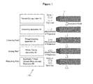
- Figure 1 is a schematic diagram to generally show a thread processing line for carrying out a method for measuring a thread element at an end portion of a pipe relating to a first embodiment of the present invention.
- thread processing is performed on an end portion of each pipe P, which is successively conveyed by a predetermined conveyance system (not shown) in a thread processing line 100.
- a pipe P is carried in in the pipe axial direction to an installation position of a thread cutting lathe 10.
- an end portion of the pipe P is subjected to thread cutting by the thread cutting lathe 10 while a lubricant (water and a rust prevention agent) is sprayed onto the end portion of the pipe P.
- the pipe P for which thread cutting on the end portion of the pipe is finished is carried out in the pipe axial direction from the thread cutting lathe 10, and is transversely fed to a position opposing the installation position of a deburring apparatus 20.
- the deburring apparatus 20 advances in the pipe axial direction toward the end portion of the pipe P. Then, deburring of the end portion of the pipe P is performed by the deburring apparatus 20.
- the deburring apparatus 20 for example, a lathe similar to the thread cutting lathe 10 is used. That is, burrs generated on the thread of the end portion of the pipe P is removed by the deburring apparatus 20 while a lubricant (water and a rust prevention agent) is sprayed on the end portion of the pipe P.
- the deburring apparatus 20 retreats to its original position after finishing the deburring of the end portion of the pipe P.
- the pipe P which has been subjected to thread processing on its end portion is transversely fed to a position opposing the installation position of a thread cleaning apparatus 30, and a cleaning step of cleaning the end portion of the pipe after thread processing is performed.
- the thread cleaning apparatus 30 advances in the pipe axial direction toward the end portion of the pipe P, and cleaning with an organic solvent is performed.
- Figures 2A and 2B are schematic diagrams to generally show an example of the thread cleaning apparatus 30 which can be used in the cleaning step of the present embodiment.
- Figure 2A shows a partial perspective front view (seeing through the interior of a housing 31), and
- Figure 2B shows a plan view. It is noted that illustration of the housing 31 and a nozzle 32 is omitted in Figure 2B .
- the thread cleaning apparatus 30 of the present embodiment includes a housing 31 positioned above the pipe P, a nozzle 32 incorporated in the housing 31, and a cleaning brush 33 positioned below the pipe P, the cleaning brush 33 being rotatable around an axis 33A.
- the housing 31, the nozzle 32, and the cleaning brush 33 advance as a single body in the axial direction of the pipe P toward an end portion of the pipe P until the nozzle 32 is positioned immediately above the threaded end portion of the pipe P, and the cleaning brush 33 is positioned immediately below the threaded end portion of the pipe P. Then, after the advance action is finished, an organic solvent S as a cleaning liquid is ejected from the nozzle 32.
- the organic solvent S ejected from the nozzle 32 is sprayed onto the end portion of the pipe P through an opening on a lower surface of the housing 31.
- the end portion of the pipe P is rubbed with the cleaning brush 33 by causing a turning roller R to circumferentially rotate the pipe P, and causing the cleaning brush 33 to rotate around the axis 33A.
- the entire circumference of the end portion of the pipe P is cleaned, and it can be expected that any lubricant remaining on the end portion of the pipe during thread cutting and deburring, and cutting chips having adhered to the end portion of the pipe as a result of deburring are removed.
- the thread cleaning apparatus 30 retreats to its original position after finishing the cleaning of the end portion of the pipe P.
- the pipe P whose end portion is cleaned is transversely fed to a position opposing the installation position of the thread drying apparatus 40, and a drying step of drying the end portion of the pipe P is performed.
- the thread drying apparatus 40 advances in the pipe axial direction toward the end portion of the pipe P, and drying by air is performed.
- Figures 3A and 3B are schematic diagrams to generally show an example of the thread drying apparatus 40 which can be used in the drying step of the present embodiment.
- Figure 3A shows a front view
- Figure 3B shows a perspective view. It is noted that illustration of a nozzle 42 is omitted in Figure 3B .
- the thread drying apparatus 40 of the present embodiment includes an annular member 41 having an inner diameter larger than the outer diameter of the pipe P, and a plurality of nozzles 42 attached to the annular member 41.
- the annular member 41 and the nozzles 42 advance as a single body toward the end portion of the pipe P to a position where they surround the threaded end portion of the pipe P. Then, after the advance action is finished, air A is ejected from the nozzle 42 toward the end portion of the pipe P.
- the organic solvent S which may remain on the end portion of the pipe P in the above described cleaning step, can be dried.
- the thread drying apparatus 40 retreats to its original position after finishing the drying of the end portion of the pipe P.
- the pipe P whose end portion is dried is transversely fed to a position opposing the installation position of an automatic thread element measurement apparatus 50 so that a measuring step of measuring thread elements at the end portion of the pipe after drying is performed under a clean atmosphere.
- the end portion of the pipe P is carried in in the pipe axial direction toward the installation position of the automatic thread element measurement apparatus 50 which is placed under a clean atmosphere.
- the automatic thread element measurement apparatus 50 is installed in a measuring chamber which is filled with clean air under a positive pressure condition, and the end portion of the pipe P is carried in into the measuring chamber from an opening portion provided in the measuring chamber so that thread elements are measured by the automatic thread element measurement apparatus 50.
- an automatic thread element measurement apparatus 50 for example, an automatic optical measurement apparatus as described in Patent Literatures 1 and 2 can be used.
- the pipe P which has undergone the measurement of thread elements is carried out to the outside of the measuring chamber through the opening portion of the measuring chamber, and is thereafter transversely fed.
- the method for measuring a thread element at an end portion of a pipe relating to the present embodiment described so far includes a cleaning step of cleaning the end portion of the pipe after thread processing (thread cutting and deburring) is performed on the end portion of the pipe, it can be expected that any lubricant remaining on the end portion of the pipe during thread cutting and deburring, and cutting chips having adhered to the end portion of the pipe as a result of deburring, which may cause deterioration of the measurement precision of thread elements, are cleaned.
- the method for measuring a thread element at an end portion of a pipe relating to the present embodiment includes a drying step of drying the end portion of the pipe after the end portion of the pipe or tube is cleaned in the cleaning step, the organic solvent S which may remain on the end portion of the pipe in the cleaning step is dried, making it possible to prevent deterioration of the measurement precision of thread elements caused by the organic solvent S.
- the method for measuring a thread element at an end portion of a pipe relating to the present embodiment includes a measuring step of measuring thread elements at an end portion of a pipe which is put under a clean atmosphere, it is possible to precisely measure thread elements.
- an end portion of the pipe P is to be exposed to the atmosphere of the thread processing line 100 for a period after the end portion of the pipe P is dried in the drying step by the thread drying apparatus 40 until thread elements at the end portion of the pipe P are measured in the measuring step by the automatic thread element measurement apparatus 50. For this reason, there is risk that particles existing in the atmosphere of the thread processing line 100 adhere to the end portion of the pipe P before thread elements at the end portion of the pipe P are measured, thereby deteriorating the measurement precision of thread elements.
- the present inventors have conducted a test to evaluate the effects of particles existing in the atmosphere of the thread processing line 100.
- the present inventors measured particle densities (the number of particles per a unit volume) at particle diameters of 0.3 ⁇ m, 0.5 ⁇ m, and 1.0 ⁇ m by using a particle counter over two days in the thread processing line 100. To measure the particle density, a commercially available particle counter was used.
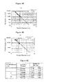
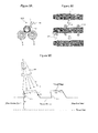
- Figure 4A is a graph to show average values within an evaluation time of measured particle densities.
- Figure 4B is a graph to show maximum values within the evaluation time of the measured particle densities.
- the present inventors estimated the particle densities at particle diameters of 5 ⁇ m and 10 ⁇ m by extrapolating measured values of particle densities at particle diameters of 0.3 ⁇ m, 0.5 ⁇ m, and 1.0 ⁇ m shown in Figures 4A and 4B (the dashed lines shown in Figures 4A and 4B indicate the extrapolation results).
- the present inventors calculated the volume of a region through which the thread part passes during the above described conveyance from a conveyance distance (supposed to be 5 m) of the thread part of the pipe P which is conveyed while being exposed to the atmosphere of the thread processing line 100, and the outer diameter and length of the thread part. Then, it was supposed that the particles existing in the calculated volume uniformly adhered to the entire thread part of the pipe P. Specifically, the particle density at a particle diameter of 1 ⁇ m measured as described above and the above described calculated volume were multiplied with each other to calculate the number of particles having a particle diameter of 1 ⁇ m which adhered to the entire thread part of the pipe P.
- the particle densities at particle diameters of 5 ⁇ m and 10 ⁇ m estimated as described above and the above described calculated volume were multiplied with each other to calculate the number of particles having particle diameters 5 ⁇ m and 10 ⁇ m which adhered to the entire thread part of the pipe P.
- the present inventors assumed that a focal depth of the light receiving means was 0.2 mm and an image pickup field of the light receiving means was 5 mm x 5 mm. Then, of the particles adhering to the entire thread part of the pipe P, the number of particles adhering to the above described evaluation area (5 mm x 5 mm x 0.2 mm) was calculated.
- Figure 4C is a diagram to show the number of particles adhering to the evaluation area, which was calculated as described above.
- the numbers of particles adhering to the evaluation area are shown for both outer diameters of the pipe P of 178 mm and 60 mm.
- the particles having a particle diameter of 5 ⁇ m will adhere to the evaluation area of the thread part of the pipe P at a probability of about 7 to 8% (in other words, the particles adhere to the evaluation area of the thread part in 7 to 8 pipes P out of 100 pipes P) when the number thereof is relatively large. Moreover, even particles having a particle diameter of 10 ⁇ m will adhere to the evaluation area of the thread part of the pipe P at a probability of about 3% when the number thereof is relatively large. Further, particles having a particle diameter of 1 ⁇ m will adhere to the evaluation area of the thread part of the pipe P at a probability of about 15% in an ordinary case, and at a probability of about 70% when the number thereof is relatively large.
- the end portion of the pipe after thread processing is preferably put under a clean atmosphere. This point is taken into consideration in the second embodiment of the present invention.
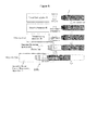
- Figure 5 is a schematic diagram to show a general configuration of a thread processing line for carrying out the method for measuring a thread element at an end portion of a pipe relating to a second embodiment of the present invention.
- a thread processing line 100A of the present embodiment As shown in Figure 5 , in a thread processing line 100A of the present embodiment as well, an end portion of each pipe P, which is successively conveyed by a predetermined conveyance system (not shown) is subjected to thread processing (thread cutting and deburring). As with the first embodiment, a thread cutting lathe 10 is used for thread cutting, and a deburring apparatus 20 is used for deburring.
- the pipe P which is threaded on an end portion is, as in the first embodiment, transversely fed to a position opposing the installation position of a thread cleaning apparatus 30, and cleaning step of cleaning the end portion of the pipe after thread processing is performed.
- the thread cleaning apparatus 30 advances in the pipe axial direction toward the end portion of the pipe P, and cleaning with an organic solvent is performed.
- the thread cleaning apparatus 30 retreats to its original position after finishing the cleaning of the end portion of the pipe P.
- the pipe P whose end portion is cleaned is transversely fed to a position opposing the installation position of a cleanness maintaining apparatus 60, and a drying step of drying the cleaned end portion of the pipe is performed. Specifically, first, the end portion of the pipe P is carried in into the cleanness maintaining apparatus 60. Then, the pipe P is transversely fed with the end portion of the pipe P being positioned in the cleanness maintaining apparatus 60, and during this period, the end portion of the pipe P is dried by clean air in the cleanness maintaining apparatus 60.
- Figures 6A and 6B are schematic diagrams to show an example of the cleanness maintaining apparatus 60 which can be used in the present embodiment.
- Figure 6A shows a perspective view
- Figure 6B shows a side sectional view.
- the cleanness maintaining apparatus 60 of the present embodiment is an application of the technical idea of "cleanness space forming apparatus" described in JP2003-248158A , proposed by the present applicant.
- the cleanness maintaining apparatus 60 of the present embodiment includes a first chamber 61, a second chamber 62, and a mesh filter 63 for partitioning the first chamber 61 from the second chamber 62 (for example, the size of mesh shall be not more than 5 ⁇ m).
- a mesh filter 63 for partitioning the first chamber 61 from the second chamber 62 (for example, the size of mesh shall be not more than 5 ⁇ m).
- One of the wall surfaces of the second chamber 62, through which the pipe P is carried in, is opened.
- a part of the wall surface of the second chamber 62 on the side opposing the measuring chamber 51 in which the automatic thread element measurement apparatus 50 is installed is also opened to communicate with the measuring chamber 51.
- Clean air under a positive pressure condition is supplied from an air supply source 64 which includes an air filter and a pressurizing apparatus, into the first chamber 61 of the cleanness maintaining apparatus 60 via a piping 65.
- the clean air supplied into the first chamber 61 passes through the mesh filter 63 and during that process, particles corresponding to the size of the mesh are removed so that the clean air is supplied to the second chamber 62.
- the clean air supplied to the second chamber 62 flows out to the outside via the opening portion of the second chamber 62.
- the cleanness maintaining apparatus 60 which has the above described configuration makes it possible to put the end portion of the pipe P under a clean atmosphere, and at the same time to dry the end portion of the pipe P in the process of the pipe P being transversely fed.
- the end portion of the pipe P is carried in into the measuring chamber 51 filled with clean air under a positive pressure condition, and thread elements are measured by an automatic thread element measurement apparatus 50 installed in the measuring chamber 51.
- the pipe P which has undergone the measurement of thread elements is carried out into the second chamber 62 via the measuring chamber 51 and the opening portions of the second chamber 62, and is further carried out to the outside of the second chamber 62 via the opening portion of the second chamber 62, thereafter being transversely fed.
- the method for measuring a thread element at an end portion of a pipe relating to the present embodiment described so far the end portion of the pipe P is put under a clean atmosphere during a period from the drying step to the measuring step.
- the method relating to the present embodiment has an advantage that the risk that particles existing in the atmosphere of the thread processing line 100A adhere to an end portion of a pipe, thereby deteriorating the measurement precision of thread elements is reduced, making it possible to measure thread elements with higher precision.
- the thread cleaning apparatus 30 and the thread drying apparatus 40 which have been described in the first embodiment, are installed in the second chamber 62.
- a space in the second chamber 62 (a thread cleaning space) in which a cleaning step is performed by using the thread cleaning apparatus 30 and a space in the second chamber 62 (a thread drying space) in which a drying step is performed by using the thread drying apparatus 40 are partitioned by a shutter 66A which is freely opened/closed.
- the thread drying space and other spaces in the second chamber 62 are partitioned by a shutter 66B which is freely opened/closed. Clean air is supplied to the thread cleaning space via a piping 65D, clean air is supplied to the thread drying space via a piping 65C, and clean air is supplied to the other spaces in the second chamber 62 via pipings 65A and 65B.
- the other configurations of the cleanness maintaining apparatus 60A are the same as those of the above described cleanness maintaining apparatus 60.
- the cleaning step is performed by the cleanness maintaining apparatus 60A having the above described configurations, an end portion of the pipe P is carried in into the thread cleaning space, and the thread cleaning apparatus 30 advances toward the end portion of the pipe P in the second chamber 62 so that cleaning with an organic solvent is performed.
- the shutter 66A is closed to prevent an organic solvent S etc. from scattering into the adjacent thread drying space.
- the thread cleaning apparatus 30 retreats to its original position after finishing the cleaning of the end portion of the pipe P.
- the shutter 66A is opened, the pipe P is transversely fed to the thread drying space with the end portion of the pipe thereof being positioned in the second chamber 62.
- the thread drying apparatus 40 advances toward an end portion of the pipe P in the second chamber 62, and drying by air is performed.
- this drying step is performed, the shutter 66B is closed to prevent the organic solvent S, etc. from scattering into adjacent spaces.
- the thread drying apparatus 40 retreats to its original position after finishing the drying of the end portion of the pipe P.
- the shutter 66B is opened, the pipe P is transversely fed to an adjacent space with the end portion of the pipe thereof being positioned in the second chamber 62.
- the above described first and second embodiments include a drying step of drying an end portion of a pipe P which has been cleaned.
- the present embodiment differs from the first and second embodiments in that the drying step is obviated since granular dry ice is ejected along with compressed air to clean the end portion of the pipe in the cleaning step.
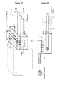
- Figures 8A, 8B, and 8C are schematic diagrams to generally show an example of the thread cleaning apparatus for carrying out the method for measuring a thread element at an end portion of a pipe relating to a third embodiment of the present invention.
- Figure 8A shows a front view
- Figure 8B shows a plan view
- Figure 8C shows an enlarged sectional view in parallel with the pipe axial direction of the end portion of the pipe.
- a thread cleaning apparatus 30A of the present embodiment includes a nozzle 34 positioned above the pipe P. The nozzle 34 advances in the axial direction of the pipe P toward an end portion of the pipe P until the nozzle 34 is positioned above the threaded end portion of the pipe P.
- granular dry ice D and compressed air are supplied to the nozzle 34 from a supply source (not shown), and the granular dry ice D is ejected along with compressed air from the nozzle 34 toward the end portion of the pipe P.
- the dry ice D ejected from the nozzle 34 is sprayed in a linear shape along the axial direction of the pipe P.
- the pipe P is rotated in the circumferential direction by a turning roller R. Also, as needed, the nozzle 34 is moved in the axial direction of the pipe P.
- the present inventors have performed cleaning as an experiment by rotating the pipe P by one revolution under conditions that an ejection angle (an angle ⁇ shown in Figure 8A ) of the dry ice D with respect to the vertical direction (a direction of V shown in Figure 8A ) was about 45°, a distance between the nozzle 34 and the pipe P was about 50 mm, a cleaning width (a width of the dry ice D sprayed in a linear shape) was about 40 mm, a cleaning length (a length of the dry ice D sprayed in a linear shape) was about 200 mm, an ejection pressure was about 0.35 MPa, and a rotational speed of the pipe P was about 10 rpm.
- the results have confirmed that any lubricant remaining on the end portion of the pipe during thread cutting and deburring, and cutting chips having adhered to the end portion of the pipe as a result of deburring are sufficiently removed.
- the rotational speed of the pipe P when an end portion of a pipe is cleaned is preferably set to about 5 rpm to 23 rpm. This is because, if the rotational speed is less than 5 rpm, dry ice D will be excessively sprayed onto the same site of the end portion of the pipe P and thereby dew condensation is likely to occur (thus impairing the advantage of the present embodiment that the drying step is obviated). On the other hand, if the rotational speed exceeds 23 rpm, there is risk that any lubricant remaining on the end portion of the pipe P during thread cutting and deburring, and cutting chips having adhered to the end portion of the pipe P as a result of deburring cannot be sufficiently cleaned.
- an upper limit to a number of revolutions of the pipe P during cleaning. This is because, if the number of revolutions is excessively large, the dry ice D is excessively sprayed on the same site on the end portion of the pipe P.
- This upper limit value which varies depending on the rotational speed of the pipe P, is preferably not more than 1 revolution when the rotational speed is 5 rpm, and not more than 5 revolutions when the rotational speed is 23 rpm.
- the present inventors performed cleaning as an experiment under the above described conditions (ejection angle ⁇ : about 45°, distance between the nozzle 34 and the pipe P: about 50 mm, the cleaning width: about 40 mm, the cleaning length: about 200 mm, the ejection pressure: about 0.35 MPa, and the rotational speed of the pipe P: about 10 rpm), and confirmed that dew condensation occurred when the pipe P was rotated by 3 revolutions (no dew condensation occurred at the number of revolutions of not more than 2).
- the nozzle 34 is inclined according to the inclination angle of the flank face.
- both of the flank faces F1 and F2 which are located between a thread ridge and a thread groove are often inclined toward the pipe end side as the position moves from the thread ridge toward the thread groove.
- the flank face F2 on the pipe end side is inclined in such a way to move apart from the thread ridge as the position moves from the thread ridge to the thread groove
- the flank face F1 on the pipe center side is often inclined in such a way to move closer to the center of the thread ridge as the position moves from the thread ridge toward the thread groove.
- an inclination angle ⁇ of the nozzle 34 with respect to the thread axial direction is preferably set to satisfy a condition: ⁇ ⁇ ⁇ ⁇ so as to clean the flank faces F1, F2.
- the inclination angle ⁇ of the nozzle 34 is preferably set so as to be 3° ⁇ ⁇ ⁇ 10°.
- the values of ⁇ and ⁇ can take various values according to the uses of the pipe P, and the like, it is preferable that the value of the inclination angle ⁇ of the nozzle 34 is not fixed, but is variable. That is, the nozzle 34 is preferably placed so as to be freely inclined with respect to the thread axial direction of the pipe P (pipe axial direction).
- the present embodiment differs from the first and second embodiments in that the drying step is obviated since an end portion of a pipe is cleaned by ejecting granular dry ice D along with compressed air in the cleaning step.
- the drying step is obviated since an end portion of a pipe is cleaned by ejecting granular dry ice D along with compressed air in the cleaning step.
- the present embodiment can appropriately adopt configurations similar to those of the first and second embodiments, the description thereof will be omitted herein.
Abstract
Description
- The present invention relates to a method for precisely measuring, automatically and on-line, thread elements at an end portion of a pipe or tube formed with a thread such as OCTG (Oil Country Tubular Goods). Hereinafter, "pipe or tube" is referred to as "pipe" when deemed appropriate.
- Traditionally, OCTG and the like have been used by connecting end portions of pipes thereof with threads formed at those end portions of pipes. Such threads have been subjected to various improvements such as in the thread shape in association with demands for deepening of oil wells, and higher resistance to corrosive environments (see, for example, Non Patent Literature 1). Such threads, which may possibly be formed at an end portion of a pipe having a length of several tens of meters and a weight of as large as several hundreds of kgf, have a complex and high precision thread shape. Meanwhile, regarding such threads, quality control items called thread elements are defined, and whether or not a measured value of a thread element is within a predetermined tolerance is inspected. Examples of the thread element include an outer diameter of the thread part, an outer diameter of the sealing part, an outer diameter of the parallel part, a diameter of the thread groove, a height of the thread ridge, a depth of the thread groove, a thread taper, a seal taper, and the like.
- While, conventionally, thread elements, which are the quality control items as described above, have been manually measured on-line (on a thread processing line) by use of a special purpose measurement instrument, attempts have been made to develop more precise automatic measurement technique in the view point of labor saving, suppression of human errors, and enhancement of the speed and precision of measurement.
- Specifically, as a technique for automatically measuring thread elements, there is known an automatic measurement apparatus which has an optical sensor, which projects parallel light from a light source onto thread grooves and detects the light that leaks out to the opposite side of the light source with respect to the pipe axis, and measures thread elements based on the detection result of the optical sensor (see, for example, Patent Literatures 1 and 2).
- [Non Patent Literature 1] Masao Ogasawara, "Current Status of Tubular Connectors for OCTG (in Japanese)," Iron and Steel: Journal of Iron and Steel Institute of Japan, Vol. 79, No. 5, PP. N352 - N355, May 1, 1993.
-
- [Patent Literature 1]
JP3552440B - [Patent Literature 2]
JP63-212808A - However, there are environmental problems in applying on-line (on a thread processing line) an automatic measurement apparatus of thread elements as described in Patent Literatures 1 and 2.
- To be Specific, when an end portion of a pipe is subjected to thread processing, generally, the end portion of the pipe is subjected to thread cutting by use of a lathe while a lubricant (water and a rust preventive agent) is sprayed onto the end portion of the pipe so that the lubricant may remain on the end portion of the pipe after thread cutting, causing deterioration of the measurement precision of thread elements. Further, when deburring is performed after cutting, in addition to any lubricant which remains as with during thread cutting, cutting chips which adhere to the end portion of the pipe as a result of deburring may cause deterioration of the measurement precision of thread elements.
- For this reason, it is practically difficult to apply an automatic measurement apparatus of thread elements on-line to perform 100 percent measurement. Therefore, conventionally, pipes are picked up at appropriate timings from the thread processing line, and automatic measurement is performed after any lubricant and cutting chips are removed in a laboratory under a good environmental condition.
- The present invention has been made to solve the above described technical problems, and has its object to provide a method for precisely measuring, automatically and on-line (on a thread processing line), thread elements at an end portion of a pipe formed with a thread.
- In order to solve the above-described problems, the present invention provides a method for automatically measuring a thread element at an end portion of a pipe or tube after thread processing is performed on the end portion of the pipe or tube, on a thread processing line in which thread processing is performed on the end portion of each pipe or tube which is successively conveyed, comprising: a cleaning step of cleaning the end portion of the pipe or tube after the thread processing is performed on the end portion of the pipe or tube; a drying step of drying the end portion of the pipe or tube after the end portion of the pipe or tube is cleaned in the cleaning step; and a measuring step of measuring the thread element at the end portion of the pipe or tube after the end portion of the pipe or tube is dried in the drying step, wherein the end portion of the pipe or tube is put under a clean atmosphere at least in the measuring step.
- Since the present invention includes a cleaning step of cleaning the end portion of the pipe or tube after thread processing is performed on the end portion of the pipe or tube, it can be expected that any lubricant remaining on the end portion of the pipe or tube during thread cutting and deburring, and cutting chips having adhered to the end portion of the pipe or tube as a result of deburring, which may cause deterioration of the measurement precision of thread elements, are cleaned. For the cleaning of an end portion of a pipe or tube in the cleaning step, for example, an organic solvent is used.
- Moreover, since the present invention includes a drying step of drying the end portion of the pipe or tube after the end portion of the pipe or tube is cleaned in the cleaning step, the organic solvent, which may remain on the end portion of the pipe or tube in the cleaning step, dries, making it possible to prevent the deterioration of measurement precision of thread elements caused by the organic solvent and the like.
- Further, since the present invention includes a measuring step of measuring the thread element at the end portion of the pipe or tube which is put under a clean atmosphere, it is possible to precisely measure the thread element. For the measurement of thread elements in the measuring step, for example, an automatic optical measurement apparatus as described in Patent Literatures 1 and 2 is used.
- As so far described, according to the present invention, it is possible to precisely measure, automatically and on-line (on a thread processing line), the thread element at an end portion of a pipe formed with a thread.
- Preferably, in the present invention, the end portion of the pipe or tube is put under a clean atmosphere at least during a period from the drying step to the measuring step after thread processing is performed on the end portion of the pipe or tube.
- If an end portion of a pipe or tube is exposed to the atmosphere of the thread processing line after any lubricant remaining on the end portion of the pipe or tube and cutting chips having adhered to the end portion of the pipe or tube are cleaned in the cleaning step, and the end portion of the pipe or tube is dried in the drying step, there is a risk that particles existing in the atmosphere in the thread processing line adhere to the end portion of the pipe or tube, causing deterioration of measurement precision of thread elements.
- However, according to the above described preferable method, since the end portion of the pipe or tube is put under a clean atmosphere at least during a period from the drying step to the measuring step, a risk that particles existing in the atmosphere of the thread processing line adhere to the end portion of the pipe or tube, thereby deteriorating the measurement precision of thread elements is reduced, thereby making it possible to measure thread elements with even more precision.
- In order to solve the above-described problems, the present invention also provides a method for automatically measuring a thread element at an end portion of a pipe or tube after thread processing is performed on the end portion of the pipe or tube, on a thread processing line in which thread processing is performed on the end portion of each pipe or tube which is successively conveyed, comprising: a cleaning step of cleaning the end portion of the pipe or tube by ejecting granular dry ice with compressed air onto the end portion of the pipe or tube after thread processing is performed on the end portion of the pipe or tube; and a measuring step of measuring the thread element at the end portion of the pipe or tube after the end portion of the pipe or tube is cleaned in the cleaning step, wherein the end portion of the pipe or tube is put under a clean atmosphere at least in the measuring step.
- Since the present invention also includes a cleaning step of cleaning the end portion of the pipe or tube after thread processing is performed on the end portion of the pipe or tube, it can be expected that any lubricant remaining on the end portion of the pipe or tube during thread cutting and deburring, and cutting chips having adhered to the end portion of the pipe or tube as a result of deburring, which may cause deterioration of measurement precision of thread elements, are cleaned.
- Moreover, since in the cleaning step of the present invention, the end portion of the pipe or tube is cleaned by ejecting granular dry ice with compressed air after thread processing is performed on the end portion of the pipe or tube, the dry ice used for cleaning will spontaneously evaporate. For this reason, there is an advantage that the drying step of drying the cleaned end portion of the pipe or tube is obviated.
- Further, since the present invention includes a measuring step of measuring the thread element at the end portion of the pipe or tube which is put under a clean atmosphere, it is possible to precisely measure the thread element. For the measurement of the thread element in the measuring step, for example, an automatic optical measurement apparatus as described in Patent Literatures 1 and 2 is used.
- As so far described, according to the present invention, it is possible to precisely measure automatically and on-line (on a thread processing line) thread elements at an end portion of a pipe formed with a thread.
- According to the method for measuring a thread element at an end portion of a pipe or tube relating to the present invention, it is possible to precisely measure, automatically and on-line (on a thread processing line), thread elements at an end portion of a pipe or tube formed with a thread. As a result of that, it is expected to enable 100 percent measurement on-line.
-
-
Figure 1 is a schematic diagram to generally show a thread processing line for carrying out a method for measuring a thread element at an end portion of a pipe relating to a first embodiment of the present invention. -
Figures 2A and 2B are schematic diagrams to generally show an example of the thread cleaning apparatus shown inFigure 1 . -
Figures 3A and 3B are schematic diagrams to generally show an example of the thread drying apparatus shown inFigure 1 . -
Figures 4A, 4B, and 4C are diagrams to show results of a test to evaluate the effect of particles existing in the atmosphere of a thread processing line. -
Figure 5 is a schematic diagram to show a general configuration of a thread processing line for carrying out the method for measuring a thread element at an end portion of a pipe relating to a second embodiment of the present invention. -
Figures 6A and 6B are schematic diagrams to show an example of the cleanness maintaining apparatus shown inFigure 5 . -
Figure 7 is a schematic diagram to generally show a variation of the cleanness maintaining apparatus shown inFigure 6 . -
Figures 8A, 8B, and 8C are schematic diagrams to generally show an example of the thread cleaning apparatus for carrying out the method for measuring a thread element at an end portion of a pipe relating to a third embodiment of the present invention. - Hereafter, embodiments of the present invention will be described appropriately referring to the appended drawings.
-
Figure 1 is a schematic diagram to generally show a thread processing line for carrying out a method for measuring a thread element at an end portion of a pipe relating to a first embodiment of the present invention. - As shown in
Figure 1 , thread processing is performed on an end portion of each pipe P, which is successively conveyed by a predetermined conveyance system (not shown) in athread processing line 100. - Specifically, first, a pipe P is carried in in the pipe axial direction to an installation position of a
thread cutting lathe 10. Next, an end portion of the pipe P is subjected to thread cutting by thethread cutting lathe 10 while a lubricant (water and a rust prevention agent) is sprayed onto the end portion of the pipe P. The pipe P for which thread cutting on the end portion of the pipe is finished is carried out in the pipe axial direction from thethread cutting lathe 10, and is transversely fed to a position opposing the installation position of a deburring apparatus 20. - Next, the deburring apparatus 20 advances in the pipe axial direction toward the end portion of the pipe P. Then, deburring of the end portion of the pipe P is performed by the deburring apparatus 20. As the deburring apparatus 20, for example, a lathe similar to the
thread cutting lathe 10 is used. That is, burrs generated on the thread of the end portion of the pipe P is removed by the deburring apparatus 20 while a lubricant (water and a rust prevention agent) is sprayed on the end portion of the pipe P. The deburring apparatus 20 retreats to its original position after finishing the deburring of the end portion of the pipe P. - As so far described, the pipe P which has been subjected to thread processing on its end portion is transversely fed to a position opposing the installation position of a
thread cleaning apparatus 30, and a cleaning step of cleaning the end portion of the pipe after thread processing is performed. Specifically, thethread cleaning apparatus 30 advances in the pipe axial direction toward the end portion of the pipe P, and cleaning with an organic solvent is performed. -
Figures 2A and 2B are schematic diagrams to generally show an example of thethread cleaning apparatus 30 which can be used in the cleaning step of the present embodiment.Figure 2A shows a partial perspective front view (seeing through the interior of a housing 31), andFigure 2B shows a plan view. It is noted that illustration of thehousing 31 and anozzle 32 is omitted inFigure 2B . - As shown in
Figures 2A and 2B , thethread cleaning apparatus 30 of the present embodiment includes ahousing 31 positioned above the pipe P, anozzle 32 incorporated in thehousing 31, and a cleaningbrush 33 positioned below the pipe P, the cleaningbrush 33 being rotatable around anaxis 33A. Thehousing 31, thenozzle 32, and the cleaningbrush 33 advance as a single body in the axial direction of the pipe P toward an end portion of the pipe P until thenozzle 32 is positioned immediately above the threaded end portion of the pipe P, and the cleaningbrush 33 is positioned immediately below the threaded end portion of the pipe P. Then, after the advance action is finished, an organic solvent S as a cleaning liquid is ejected from thenozzle 32. The organic solvent S ejected from thenozzle 32 is sprayed onto the end portion of the pipe P through an opening on a lower surface of thehousing 31. In this occasion, the end portion of the pipe P is rubbed with the cleaningbrush 33 by causing a turning roller R to circumferentially rotate the pipe P, and causing the cleaningbrush 33 to rotate around theaxis 33A. As a result of the above described actions, the entire circumference of the end portion of the pipe P is cleaned, and it can be expected that any lubricant remaining on the end portion of the pipe during thread cutting and deburring, and cutting chips having adhered to the end portion of the pipe as a result of deburring are removed. - The
thread cleaning apparatus 30 retreats to its original position after finishing the cleaning of the end portion of the pipe P. - Next, as shown in
Figure 1 , the pipe P whose end portion is cleaned is transversely fed to a position opposing the installation position of thethread drying apparatus 40, and a drying step of drying the end portion of the pipe P is performed. Specifically, thethread drying apparatus 40 advances in the pipe axial direction toward the end portion of the pipe P, and drying by air is performed. -
Figures 3A and 3B are schematic diagrams to generally show an example of thethread drying apparatus 40 which can be used in the drying step of the present embodiment.Figure 3A shows a front view, andFigure 3B shows a perspective view. It is noted that illustration of anozzle 42 is omitted inFigure 3B . - As shown in
Figures 3A and 3B , thethread drying apparatus 40 of the present embodiment includes anannular member 41 having an inner diameter larger than the outer diameter of the pipe P, and a plurality ofnozzles 42 attached to theannular member 41. Theannular member 41 and thenozzles 42 advance as a single body toward the end portion of the pipe P to a position where they surround the threaded end portion of the pipe P. Then, after the advance action is finished, air A is ejected from thenozzle 42 toward the end portion of the pipe P. As a result of the above described actions, it is expected that the organic solvent S, which may remain on the end portion of the pipe P in the above described cleaning step, can be dried. - The
thread drying apparatus 40 retreats to its original position after finishing the drying of the end portion of the pipe P. - Finally, as shown in
Figure 1 , the pipe P whose end portion is dried is transversely fed to a position opposing the installation position of an automatic thread element measurement apparatus 50 so that a measuring step of measuring thread elements at the end portion of the pipe after drying is performed under a clean atmosphere. Specifically, the end portion of the pipe P is carried in in the pipe axial direction toward the installation position of the automatic thread element measurement apparatus 50 which is placed under a clean atmosphere. More specifically, the automatic thread element measurement apparatus 50 is installed in a measuring chamber which is filled with clean air under a positive pressure condition, and the end portion of the pipe P is carried in into the measuring chamber from an opening portion provided in the measuring chamber so that thread elements are measured by the automatic thread element measurement apparatus 50. As the automatic thread element measurement apparatus 50, for example, an automatic optical measurement apparatus as described in Patent Literatures 1 and 2 can be used. The pipe P which has undergone the measurement of thread elements is carried out to the outside of the measuring chamber through the opening portion of the measuring chamber, and is thereafter transversely fed. - Since the method for measuring a thread element at an end portion of a pipe relating to the present embodiment described so far includes a cleaning step of cleaning the end portion of the pipe after thread processing (thread cutting and deburring) is performed on the end portion of the pipe, it can be expected that any lubricant remaining on the end portion of the pipe during thread cutting and deburring, and cutting chips having adhered to the end portion of the pipe as a result of deburring, which may cause deterioration of the measurement precision of thread elements, are cleaned.
- Moreover, since the method for measuring a thread element at an end portion of a pipe relating to the present embodiment includes a drying step of drying the end portion of the pipe after the end portion of the pipe or tube is cleaned in the cleaning step, the organic solvent S which may remain on the end portion of the pipe in the cleaning step is dried, making it possible to prevent deterioration of the measurement precision of thread elements caused by the organic solvent S.
- Further, since the method for measuring a thread element at an end portion of a pipe relating to the present embodiment includes a measuring step of measuring thread elements at an end portion of a pipe which is put under a clean atmosphere, it is possible to precisely measure thread elements.
- It is noted that, in the present embodiment, description has been made on a mode in which the deburring apparatus 20, the
thread cleaning apparatus 30, and thethread drying apparatus 40 advance in the pipe axial direction toward an end portion of the pipe P, and retreat to their original positions after the deburring, cleaning, and drying of the end portion of the pipe P are finished. However, the present invention will not be limited to such a mode, and it is also possible to adopt a mode in which the pipe P is carried in in the pipe axial direction toward the installation position of each apparatus 20 to 40, and is carried out in the pipe axial direction from each apparatus 20 to 40 after the deburring, cleaning, and drying of the end portion of the pipe P are finished. - In the above described first embodiment, an end portion of the pipe P is to be exposed to the atmosphere of the
thread processing line 100 for a period after the end portion of the pipe P is dried in the drying step by thethread drying apparatus 40 until thread elements at the end portion of the pipe P are measured in the measuring step by the automatic thread element measurement apparatus 50. For this reason, there is risk that particles existing in the atmosphere of thethread processing line 100 adhere to the end portion of the pipe P before thread elements at the end portion of the pipe P are measured, thereby deteriorating the measurement precision of thread elements. - Accordingly, the present inventors have conducted a test to evaluate the effects of particles existing in the atmosphere of the
thread processing line 100. - First, the present inventors measured particle densities (the number of particles per a unit volume) at particle diameters of 0.3 µm, 0.5 µm, and 1.0 µm by using a particle counter over two days in the
thread processing line 100. To measure the particle density, a commercially available particle counter was used. -
Figure 4A is a graph to show average values within an evaluation time of measured particle densities.Figure 4B is a graph to show maximum values within the evaluation time of the measured particle densities. The present inventors estimated the particle densities at particle diameters of 5 µm and 10 µm by extrapolating measured values of particle densities at particle diameters of 0.3 µm, 0.5 µm, and 1.0 µm shown inFigures 4A and 4B (the dashed lines shown inFigures 4A and 4B indicate the extrapolation results). - Next, the present inventors calculated the volume of a region through which the thread part passes during the above described conveyance from a conveyance distance (supposed to be 5 m) of the thread part of the pipe P which is conveyed while being exposed to the atmosphere of the
thread processing line 100, and the outer diameter and length of the thread part. Then, it was supposed that the particles existing in the calculated volume uniformly adhered to the entire thread part of the pipe P. Specifically, the particle density at a particle diameter of 1 µm measured as described above and the above described calculated volume were multiplied with each other to calculate the number of particles having a particle diameter of 1 µm which adhered to the entire thread part of the pipe P. Moreover, the particle densities at particle diameters of 5 µm and 10 µm estimated as described above and the above described calculated volume were multiplied with each other to calculate the number of particles having particle diameters 5 µm and 10 µm which adhered to the entire thread part of the pipe P. - Further, supposing a case in which an optical measurement apparatus including a light source and light receiving means was used as the thread element measurement apparatus, the present inventors assumed that a focal depth of the light receiving means was 0.2 mm and an image pickup field of the light receiving means was 5 mm x 5 mm. Then, of the particles adhering to the entire thread part of the pipe P, the number of particles adhering to the above described evaluation area (5 mm x 5 mm x 0.2 mm) was calculated.
-
Figure 4C is a diagram to show the number of particles adhering to the evaluation area, which was calculated as described above. InFigure 4C , the numbers of particles adhering to the evaluation area are shown for both outer diameters of the pipe P of 178 mm and 60 mm. - As seen from
Figure 4C , the particles having a particle diameter of 5 µm will adhere to the evaluation area of the thread part of the pipe P at a probability of about 7 to 8% (in other words, the particles adhere to the evaluation area of the thread part in 7 to 8 pipes P out of 100 pipes P) when the number thereof is relatively large. Moreover, even particles having a particle diameter of 10 µm will adhere to the evaluation area of the thread part of the pipe P at a probability of about 3% when the number thereof is relatively large. Further, particles having a particle diameter of 1 µm will adhere to the evaluation area of the thread part of the pipe P at a probability of about 15% in an ordinary case, and at a probability of about 70% when the number thereof is relatively large. - Since a required measurement precision of thread elements is about 5 µm, the effects of the above described particles cannot be ignored when it is attempted to measure all the pipes P with high precision.
- For that reason, at least during a period from the drying step (the step of drying a cleaned end portion of a pipe) to the measuring step (the step of measuring thread elements at an end portion of a pipe), the end portion of the pipe after thread processing is preferably put under a clean atmosphere. This point is taken into consideration in the second embodiment of the present invention.
- Hereafter, regarding the second embodiment of the present invention, those points that differ from the above described first embodiment will be mainly described, and description on those points that are similar to the first embodiment will be appropriately omitted.
-
Figure 5 is a schematic diagram to show a general configuration of a thread processing line for carrying out the method for measuring a thread element at an end portion of a pipe relating to a second embodiment of the present invention. - As shown in
Figure 5 , in athread processing line 100A of the present embodiment as well, an end portion of each pipe P, which is successively conveyed by a predetermined conveyance system (not shown) is subjected to thread processing (thread cutting and deburring). As with the first embodiment, athread cutting lathe 10 is used for thread cutting, and a deburring apparatus 20 is used for deburring. - The pipe P which is threaded on an end portion is, as in the first embodiment, transversely fed to a position opposing the installation position of a
thread cleaning apparatus 30, and cleaning step of cleaning the end portion of the pipe after thread processing is performed. Specifically, thethread cleaning apparatus 30 advances in the pipe axial direction toward the end portion of the pipe P, and cleaning with an organic solvent is performed. Thethread cleaning apparatus 30 retreats to its original position after finishing the cleaning of the end portion of the pipe P. - Next, as shown in
Figure 5 , the pipe P whose end portion is cleaned is transversely fed to a position opposing the installation position of acleanness maintaining apparatus 60, and a drying step of drying the cleaned end portion of the pipe is performed. Specifically, first, the end portion of the pipe P is carried in into thecleanness maintaining apparatus 60. Then, the pipe P is transversely fed with the end portion of the pipe P being positioned in thecleanness maintaining apparatus 60, and during this period, the end portion of the pipe P is dried by clean air in thecleanness maintaining apparatus 60. -
Figures 6A and 6B are schematic diagrams to show an example of thecleanness maintaining apparatus 60 which can be used in the present embodiment.Figure 6A shows a perspective view, andFigure 6B shows a side sectional view. - The
cleanness maintaining apparatus 60 of the present embodiment is an application of the technical idea of "cleanness space forming apparatus" described inJP2003-248158A - Specifically, as shown in
Figures 6A and 6B , thecleanness maintaining apparatus 60 of the present embodiment includes afirst chamber 61, asecond chamber 62, and amesh filter 63 for partitioning thefirst chamber 61 from the second chamber 62 (for example, the size of mesh shall be not more than 5 µm). One of the wall surfaces of thesecond chamber 62, through which the pipe P is carried in, is opened. Moreover, a part of the wall surface of thesecond chamber 62 on the side opposing the measuringchamber 51 in which the automatic thread element measurement apparatus 50 is installed (area through which the pipe P is carried in into the measuring chamber 51) is also opened to communicate with the measuringchamber 51. - Clean air under a positive pressure condition is supplied from an
air supply source 64 which includes an air filter and a pressurizing apparatus, into thefirst chamber 61 of thecleanness maintaining apparatus 60 via a piping 65. The clean air supplied into thefirst chamber 61 passes through themesh filter 63 and during that process, particles corresponding to the size of the mesh are removed so that the clean air is supplied to thesecond chamber 62. The clean air supplied to thesecond chamber 62 flows out to the outside via the opening portion of thesecond chamber 62. - The
cleanness maintaining apparatus 60 which has the above described configuration makes it possible to put the end portion of the pipe P under a clean atmosphere, and at the same time to dry the end portion of the pipe P in the process of the pipe P being transversely fed. - Finally, the end portion of the pipe P is carried in into the measuring
chamber 51 filled with clean air under a positive pressure condition, and thread elements are measured by an automatic thread element measurement apparatus 50 installed in the measuringchamber 51. The pipe P which has undergone the measurement of thread elements is carried out into thesecond chamber 62 via the measuringchamber 51 and the opening portions of thesecond chamber 62, and is further carried out to the outside of thesecond chamber 62 via the opening portion of thesecond chamber 62, thereafter being transversely fed. - According to the method for measuring a thread element at an end portion of a pipe relating to the present embodiment described so far, the end portion of the pipe P is put under a clean atmosphere during a period from the drying step to the measuring step. As a result of this, in addition to the advantages of the method relating to the first embodiment described above, the method relating to the present embodiment has an advantage that the risk that particles existing in the atmosphere of the
thread processing line 100A adhere to an end portion of a pipe, thereby deteriorating the measurement precision of thread elements is reduced, making it possible to measure thread elements with higher precision. - It is noted that although, in the present embodiment, description has been made on a mode in which an end portion of a pipe is dried with clean air in the
cleanness maintaining apparatus 60, the present invention will not be limited to such a mode. For example, it is also possible to adopt a mode in which thethread drying apparatus 40 which has been described in the first embodiment is installed in thecleanness maintaining apparatus 60 so that the end portion of the pipe is dried by this dryingapparatus 40. - Moreover, although in the present embodiment, description has been made on a mode in which an end portion of the pipe P is put under a clean atmosphere during a period from the drying step to the measuring step, the present invention will not be limited to such a mode. For example, it is possible to adopt a mode in which a
cleanness maintaining apparatus 60A as shown inFigure 7 is used so that the end portion of the pipe P is put under a clean atmosphere during a period from the cleaning step to the measuring step. - Describing more specifically, in the
cleanness maintaining apparatus 60A shown inFigure 7 , thethread cleaning apparatus 30 and thethread drying apparatus 40, which have been described in the first embodiment, are installed in thesecond chamber 62. Moreover, a space in the second chamber 62 (a thread cleaning space) in which a cleaning step is performed by using thethread cleaning apparatus 30 and a space in the second chamber 62 (a thread drying space) in which a drying step is performed by using thethread drying apparatus 40 are partitioned by ashutter 66A which is freely opened/closed. Further, the thread drying space and other spaces in thesecond chamber 62 are partitioned by ashutter 66B which is freely opened/closed. Clean air is supplied to the thread cleaning space via apiping 65D, clean air is supplied to the thread drying space via a piping 65C, and clean air is supplied to the other spaces in thesecond chamber 62 viapipings 65A and 65B. - The other configurations of the
cleanness maintaining apparatus 60A are the same as those of the above describedcleanness maintaining apparatus 60. - When the cleaning step is performed by the
cleanness maintaining apparatus 60A having the above described configurations, an end portion of the pipe P is carried in into the thread cleaning space, and thethread cleaning apparatus 30 advances toward the end portion of the pipe P in thesecond chamber 62 so that cleaning with an organic solvent is performed. When this cleaning step is performed, theshutter 66A is closed to prevent an organic solvent S etc. from scattering into the adjacent thread drying space. Thethread cleaning apparatus 30 retreats to its original position after finishing the cleaning of the end portion of the pipe P. Next, theshutter 66A is opened, the pipe P is transversely fed to the thread drying space with the end portion of the pipe thereof being positioned in thesecond chamber 62. - When the drying step is performed, the
thread drying apparatus 40 advances toward an end portion of the pipe P in thesecond chamber 62, and drying by air is performed. When this drying step is performed, theshutter 66B is closed to prevent the organic solvent S, etc. from scattering into adjacent spaces. Thethread drying apparatus 40 retreats to its original position after finishing the drying of the end portion of the pipe P. Next, theshutter 66B is opened, the pipe P is transversely fed to an adjacent space with the end portion of the pipe thereof being positioned in thesecond chamber 62. - Since actions hereafter are the same as those in the case where the above described
cleanness maintaining apparatus 60 is used, description thereof will be omitted. - According to the method by use of the
cleanness maintaining apparatus 60A described so far, since an end portion of the pipe P is put under a clean atmosphere during a period from the cleaning step to the measuring step, it can be expected to further reduce the risk that particles existing in the atmosphere in thethread processing line 100A adhere to the end portion of the pipe thereby deteriorating the measurement precision of the thread elements. - It is noted that although, in the method using the
cleanness maintaining apparatus 60A described so far, description has been made on a mode in which an end portion of a pipe is dried by using thethread drying apparatus 40, it is also possible, as in the case of thecleanness maintaining apparatus 60, to adopt a mode in which the end portion of the pipe is dried by clean air in thecleanness maintaining apparatus 60A without installing thethread drying apparatus 40. - The above described first and second embodiments include a drying step of drying an end portion of a pipe P which has been cleaned. However, the present embodiment differs from the first and second embodiments in that the drying step is obviated since granular dry ice is ejected along with compressed air to clean the end portion of the pipe in the cleaning step.
-
Figures 8A, 8B, and 8C are schematic diagrams to generally show an example of the thread cleaning apparatus for carrying out the method for measuring a thread element at an end portion of a pipe relating to a third embodiment of the present invention.Figure 8A shows a front view,Figure 8B shows a plan view, andFigure 8C shows an enlarged sectional view in parallel with the pipe axial direction of the end portion of the pipe. As shown inFigures 8A, 8B, and 8C , a thread cleaning apparatus 30A of the present embodiment includes anozzle 34 positioned above the pipe P. Thenozzle 34 advances in the axial direction of the pipe P toward an end portion of the pipe P until thenozzle 34 is positioned above the threaded end portion of the pipe P. Then, after the advance action is finished, granular dry ice D and compressed air are supplied to thenozzle 34 from a supply source (not shown), and the granular dry ice D is ejected along with compressed air from thenozzle 34 toward the end portion of the pipe P. The dry ice D ejected from thenozzle 34 is sprayed in a linear shape along the axial direction of the pipe P. In this occasion, the pipe P is rotated in the circumferential direction by a turning roller R. Also, as needed, thenozzle 34 is moved in the axial direction of the pipe P. As a result of the above described actions, the entire circumference of the end portion of the pipe P is cleaned, and thereby it can be expected that any lubricant remaining on the end portion of the pipe during thread cutting and deburring, and cutting chips having adhered to the end portion of the pipe as a result of deburring are removed. - The present inventors have performed cleaning as an experiment by rotating the pipe P by one revolution under conditions that an ejection angle (an angle θ shown in
Figure 8A ) of the dry ice D with respect to the vertical direction (a direction of V shown inFigure 8A ) was about 45°, a distance between thenozzle 34 and the pipe P was about 50 mm, a cleaning width (a width of the dry ice D sprayed in a linear shape) was about 40 mm, a cleaning length (a length of the dry ice D sprayed in a linear shape) was about 200 mm, an ejection pressure was about 0.35 MPa, and a rotational speed of the pipe P was about 10 rpm. The results have confirmed that any lubricant remaining on the end portion of the pipe during thread cutting and deburring, and cutting chips having adhered to the end portion of the pipe as a result of deburring are sufficiently removed. - Here, the rotational speed of the pipe P when an end portion of a pipe is cleaned is preferably set to about 5 rpm to 23 rpm. This is because, if the rotational speed is less than 5 rpm, dry ice D will be excessively sprayed onto the same site of the end portion of the pipe P and thereby dew condensation is likely to occur (thus impairing the advantage of the present embodiment that the drying step is obviated). On the other hand, if the rotational speed exceeds 23 rpm, there is risk that any lubricant remaining on the end portion of the pipe P during thread cutting and deburring, and cutting chips having adhered to the end portion of the pipe P as a result of deburring cannot be sufficiently cleaned.
- Moreover, to prevent dew condensation caused by cleaning, it is preferable to set an upper limit to a number of revolutions of the pipe P during cleaning. This is because, if the number of revolutions is excessively large, the dry ice D is excessively sprayed on the same site on the end portion of the pipe P. This upper limit value, which varies depending on the rotational speed of the pipe P, is preferably not more than 1 revolution when the rotational speed is 5 rpm, and not more than 5 revolutions when the rotational speed is 23 rpm. The present inventors performed cleaning as an experiment under the above described conditions (ejection angle θ: about 45°, distance between the
nozzle 34 and the pipe P: about 50 mm, the cleaning width: about 40 mm, the cleaning length: about 200 mm, the ejection pressure: about 0.35 MPa, and the rotational speed of the pipe P: about 10 rpm), and confirmed that dew condensation occurred when the pipe P was rotated by 3 revolutions (no dew condensation occurred at the number of revolutions of not more than 2). - Further, to effectively clean flank faces of a thread part formed at an end portion of the pipe P, it is preferable that the
nozzle 34 is inclined according to the inclination angle of the flank face. - In a thread part when the pipe P is OCTG etc., as shown in
Figure 8C , both of the flank faces F1 and F2 which are located between a thread ridge and a thread groove are often inclined toward the pipe end side as the position moves from the thread ridge toward the thread groove. In other words, of the both flank faces F1 and F2, the flank face F2 on the pipe end side is inclined in such a way to move apart from the thread ridge as the position moves from the thread ridge to the thread groove, while the flank face F1 on the pipe center side is often inclined in such a way to move closer to the center of the thread ridge as the position moves from the thread ridge toward the thread groove. Then, if it is supposed that the inclination angle of the flank face F1 (an inclination angle with respect to a direction N perpendicular to the thread axis) is β and the inclination angle of the flank face F2 (an inclination angle with respect to a direction N perpendicular to the thread axis) is γ, a condition: β < γ is satisfied in many cases. - In this occasion, an inclination angle α of the
nozzle 34 with respect to the thread axial direction (an angle formed by the ejection direction of the dry ice D from thenozzle 34 with respect to the direction N perpendicular to the thread axis (the center of the ejection direction is C)) is preferably set to satisfy a condition: β < α < γ so as to clean the flank faces F1, F2. For example, when β = 3° and γ = 10°, the inclination angle α of thenozzle 34 is preferably set so as to be 3° < α < 10°. Moreover, since the values of β and γ can take various values according to the uses of the pipe P, and the like, it is preferable that the value of the inclination angle α of thenozzle 34 is not fixed, but is variable. That is, thenozzle 34 is preferably placed so as to be freely inclined with respect to the thread axial direction of the pipe P (pipe axial direction). - As so far described, the present embodiment differs from the first and second embodiments in that the drying step is obviated since an end portion of a pipe is cleaned by ejecting granular dry ice D along with compressed air in the cleaning step. However, as for other configurations, since the present embodiment can appropriately adopt configurations similar to those of the first and second embodiments, the description thereof will be omitted herein.
-
- 10
- Thread cutting lathe
- 20
- Deburring apparatus
- 30
- Thread cleaning apparatus
- 40
- Thread drying apparatus
- 50
- Automatic thread element measurement apparatus
- 100
- Thread processing line
- P
- Pipe
Claims (3)
- A method for automatically measuring a thread element at an end portion of a pipe or tube after thread processing is performed on the end portion of the pipe or tube, on a thread processing line in which thread processing is performed on the end portion of each pipe or tube which is successively conveyed, comprising:a cleaning step of cleaning the end portion of the pipe or tube after the thread processing is performed on the end portion of the pipe or tube;a drying step of drying the end portion of the pipe or tube after the end portion of the pipe or tube is cleaned in the cleaning step; anda measuring step of measuring the thread element at the end portion of the pipe or tube after the end portion of the pipe or tube is dried in the drying step, whereinthe end portion of the pipe or tube is put under a clean atmosphere at least in the measuring step.
- The method for measuring a thread element at an end portion of a pipe or tube according to claim 1, wherein
the end portion of the pipe or tube is put under a clean atmosphere at least during a period from the drying step to the measuring step after thread processing is performed on the end portion of the pipe or tube. - A method for automatically measuring a thread element at an end portion of a pipe or tube after thread processing is performed on the end portion of the pipe or tube, on a thread processing line in which thread processing is performed on the end portion of each pipe or tube which is successively conveyed, comprising:a cleaning step of cleaning the end portion of the pipe or tube by ejecting granular dry ice with compressed air onto the end portion of the pipe or tube after thread processing is performed on the end portion of the pipe or tube; anda measuring step of measuring the thread element at the end portion of the pipe or tube after the end portion of the pipe or tube is cleaned in the cleaning step, whereinthe end portion of the pipe or tube is put under a clean atmosphere at least in the measuring step.
Applications Claiming Priority (1)
| Application Number | Priority Date | Filing Date | Title |
|---|---|---|---|
| PCT/JP2011/070785 WO2013038485A1 (en) | 2011-09-13 | 2011-09-13 | Method for measuring threaded element at tube end |
Publications (3)
| Publication Number | Publication Date |
|---|---|
| EP2767799A1 true EP2767799A1 (en) | 2014-08-20 |
| EP2767799A4 EP2767799A4 (en) | 2015-06-24 |
| EP2767799B1 EP2767799B1 (en) | 2018-12-12 |
Family
ID=46498715
Family Applications (1)
| Application Number | Title | Priority Date | Filing Date |
|---|---|---|---|
| EP11872503.5A Active EP2767799B1 (en) | 2011-09-13 | 2011-09-13 | Method for measuring threaded element at tube end |
Country Status (6)
| Country | Link |
|---|---|
| US (1) | US9267900B2 (en) |
| EP (1) | EP2767799B1 (en) |
| JP (1) | JP4947452B1 (en) |
| CN (1) | CN103917846B (en) |
| BR (1) | BR112014005671B1 (en) |
| WO (1) | WO2013038485A1 (en) |
Cited By (2)
| Publication number | Priority date | Publication date | Assignee | Title |
|---|---|---|---|---|
| WO2022083945A1 (en) * | 2020-10-22 | 2022-04-28 | Sms Group Gmbh | Method for producing a thread on at least one end of at least one metal tube, and thread-cutting facility |
| US11340062B2 (en) | 2017-11-13 | 2022-05-24 | Voestalpine Tubulars Gmbh & Co Kg | Device for optically measuring the external-thread profile of a pipe |
Families Citing this family (3)
| Publication number | Priority date | Publication date | Assignee | Title |
|---|---|---|---|---|
| JP2015050402A (en) * | 2013-09-04 | 2015-03-16 | 株式会社ディスコ | Cutting device including cleaning means |
| JOP20200120A1 (en) * | 2013-10-21 | 2017-06-16 | Esco Group Llc | Wear assembly removal and installation |
| US11597022B2 (en) | 2020-11-05 | 2023-03-07 | Emerson Professional Tools, Llc | Algorithms and methods for controlling threading of pipe |
Family Cites Families (21)
| Publication number | Priority date | Publication date | Assignee | Title |
|---|---|---|---|---|
| DE3306194A1 (en) * | 1982-02-25 | 1983-09-08 | Mitsubishi Denki K.K., Tokyo | METHOD FOR TESTING SCREW SURFACES FOR FAULTS AND DEVICE FOR IMPLEMENTING THEM |
| GB8320292D0 (en) * | 1983-07-27 | 1983-09-01 | Ramco Oilfield & Marine Servic | Pipe cleaning/treating plant |
| JPS6115749A (en) | 1984-07-03 | 1986-01-23 | Toho Gas Kk | Cleaning method by dry ice |
| CH666547A5 (en) | 1984-12-20 | 1988-07-29 | Fischer Ag Georg | OPTICAL-ELECTRONIC MEASURING METHOD, A DEVICE REQUIRED FOR THIS AND ITS USE. |
| JPS63212808A (en) | 1987-02-27 | 1988-09-05 | Sumitomo Metal Ind Ltd | Measuring apparatus of shape of screw |
| JPH01124282A (en) | 1987-11-09 | 1989-05-17 | Hitachi Ltd | Wiring structure body and its formation |
| JPH01124282U (en) * | 1988-02-12 | 1989-08-24 | ||
| JP2892693B2 (en) | 1989-07-25 | 1999-05-17 | 株式会社放電精密加工研究所 | Tire mold |
| JPH0357606U (en) * | 1989-10-09 | 1991-06-04 | ||
| US5521707A (en) * | 1991-08-21 | 1996-05-28 | Apeiron, Inc. | Laser scanning method and apparatus for rapid precision measurement of thread form |
| JP3149990B2 (en) | 1992-06-26 | 2001-03-26 | 株式会社リコー | Toner for developing electrostatic images |
| JPH0611881U (en) | 1992-07-17 | 1994-02-15 | 住友金属工業株式会社 | Cleaning and drying device for pipe end thread |
| JP3412950B2 (en) * | 1995-03-13 | 2003-06-03 | 株式会社東芝 | Optical path protection structure of rolling measuring instrument |
| US6111601A (en) * | 1995-12-11 | 2000-08-29 | Adachi; Yoshi | Non-contacting laser gauge for qualifying screw fasteners and the like |
| JP3552440B2 (en) | 1996-01-25 | 2004-08-11 | Jfeスチール株式会社 | Method and apparatus for measuring screw element |
| US6027568A (en) * | 1996-06-12 | 2000-02-22 | Nd Industries, Inc. | Apparatus for processing fasteners |
| ATE279300T1 (en) | 2000-08-22 | 2004-10-15 | Linde Ag | METHOD AND DEVICE FOR REMOVAL OF METAL CONTAMINANTS |
| JP2002177828A (en) | 2000-12-12 | 2002-06-25 | Canon Inc | Cleaning method, apparatus therefor, object cleaned therewith, and hopper |
| JP2003248158A (en) | 2001-11-14 | 2003-09-05 | Sumitomo Metal Ind Ltd | Clean space forming apparatus |
| DE102007017747B4 (en) | 2007-04-12 | 2009-05-07 | V & M Deutschland Gmbh | Method and device for the optical measurement of external threads |
| JP2011203220A (en) | 2010-03-26 | 2011-10-13 | Sumitomo Metal Ind Ltd | Screw element measuring method of tube end |
-
2011
- 2011-09-13 US US14/343,903 patent/US9267900B2/en active Active
- 2011-09-13 EP EP11872503.5A patent/EP2767799B1/en active Active
- 2011-09-13 JP JP2011538788A patent/JP4947452B1/en active Active
- 2011-09-13 WO PCT/JP2011/070785 patent/WO2013038485A1/en active Application Filing
- 2011-09-13 CN CN201180074668.5A patent/CN103917846B/en active Active
- 2011-09-13 BR BR112014005671-4A patent/BR112014005671B1/en active IP Right Grant
Cited By (2)
| Publication number | Priority date | Publication date | Assignee | Title |
|---|---|---|---|---|
| US11340062B2 (en) | 2017-11-13 | 2022-05-24 | Voestalpine Tubulars Gmbh & Co Kg | Device for optically measuring the external-thread profile of a pipe |
| WO2022083945A1 (en) * | 2020-10-22 | 2022-04-28 | Sms Group Gmbh | Method for producing a thread on at least one end of at least one metal tube, and thread-cutting facility |
Also Published As
| Publication number | Publication date |
|---|---|
| US20140226154A1 (en) | 2014-08-14 |
| BR112014005671B1 (en) | 2020-10-06 |
| JPWO2013038485A1 (en) | 2015-03-23 |
| WO2013038485A1 (en) | 2013-03-21 |
| BR112014005671A2 (en) | 2017-03-28 |
| EP2767799B1 (en) | 2018-12-12 |
| US9267900B2 (en) | 2016-02-23 |
| JP4947452B1 (en) | 2012-06-06 |
| EP2767799A4 (en) | 2015-06-24 |
| CN103917846B (en) | 2017-03-22 |
| CN103917846A (en) | 2014-07-09 |
Similar Documents
| Publication | Publication Date | Title |
|---|---|---|
| US9267900B2 (en) | Method for measuring thread element at end portion of pipe or tube | |
| DE102015106777B4 (en) | Method and inspection system for determining and checking the surface cleanliness of industrially cleaned workpieces or machine components | |
| EP1773509A2 (en) | Method for coating tubes | |
| EP2325394B2 (en) | Method and device for applying a liquid to a rope | |
| WO2016180521A1 (en) | Application device, coating system and method for coating objects | |
| KR101647269B1 (en) | Method and apparatus for manufacturing leakage detecting sensor pipe | |
| DE10044592C1 (en) | Turning and quality assurance procedures | |
| US8614796B2 (en) | Measuring station for high-gloss surfaces | |
| US4787549A (en) | Automatic pipe inspection and repair system | |
| JP2011203220A (en) | Screw element measuring method of tube end | |
| CN104532882B (en) | Harbour steel-pipe pile scene method for anticorrosion treatment | |
| US10416061B2 (en) | Blank washer inspection system | |
| CN216590368U (en) | Device, pipe and line system for producing a number of pipes having a predetermined pipe diameter | |
| JP7358027B2 (en) | Oil piping internal lining construction method | |
| DE4439953C2 (en) | Automatic testing of deep holes | |
| CN111337570B (en) | Ultrasonic flaw detection system for nuclear-grade stainless steel outer sleeve and flaw detection method thereof | |
| RU2727419C1 (en) | Method of producing steel fuel-conducting tube | |
| JP6951042B2 (en) | Oil pipe internal lining construction method | |
| EA000285B1 (en) | Method of pipe repair and preparation for use of threaded oil pipes and mobile repair complex thereof | |
| CN101585040A (en) | Pipeline cleaner | |
| WO2023006327A1 (en) | Monopile coating process, monopile and monopile coating system | |
| CN117664996A (en) | Fluorescent penetration detection method for inner wall surface of long-axis part | |
| DE102013107560B4 (en) | Method and device for testing rolling elements using ultrasound | |
| WO2018173320A1 (en) | Internal lining installation method for oil pipe | |
| CN101758047A (en) | Pipeline cleaning device |
Legal Events
| Date | Code | Title | Description |
|---|---|---|---|
| PUAI | Public reference made under article 153(3) epc to a published international application that has entered the european phase |
Free format text: ORIGINAL CODE: 0009012 |
|
| 17P | Request for examination filed |
Effective date: 20140331 |
|
| AK | Designated contracting states |
Kind code of ref document: A1 Designated state(s): AL AT BE BG CH CY CZ DE DK EE ES FI FR GB GR HR HU IE IS IT LI LT LU LV MC MK MT NL NO PL PT RO RS SE SI SK SM TR |
|
| DAX | Request for extension of the european patent (deleted) | ||
| RA4 | Supplementary search report drawn up and despatched (corrected) |
Effective date: 20150528 |
|
| RIC1 | Information provided on ipc code assigned before grant |
Ipc: B08B 3/02 20060101ALI20150521BHEP Ipc: G01N 21/95 20060101ALI20150521BHEP Ipc: B08B 1/04 20060101ALI20150521BHEP Ipc: B08B 9/02 20060101ALI20150521BHEP Ipc: G01B 21/20 20060101AFI20150521BHEP Ipc: B08B 1/00 20060101ALI20150521BHEP Ipc: G01B 11/24 20060101ALI20150521BHEP Ipc: B08B 9/023 20060101ALI20150521BHEP |
|
| GRAP | Despatch of communication of intention to grant a patent |
Free format text: ORIGINAL CODE: EPIDOSNIGR1 |
|
| STAA | Information on the status of an ep patent application or granted ep patent |
Free format text: STATUS: GRANT OF PATENT IS INTENDED |
|
| INTG | Intention to grant announced |
Effective date: 20180625 |
|
| GRAS | Grant fee paid |
Free format text: ORIGINAL CODE: EPIDOSNIGR3 |
|
| GRAA | (expected) grant |
Free format text: ORIGINAL CODE: 0009210 |
|
| STAA | Information on the status of an ep patent application or granted ep patent |
Free format text: STATUS: THE PATENT HAS BEEN GRANTED |
|
| AK | Designated contracting states |
Kind code of ref document: B1 Designated state(s): AL AT BE BG CH CY CZ DE DK EE ES FI FR GB GR HR HU IE IS IT LI LT LU LV MC MK MT NL NO PL PT RO RS SE SI SK SM TR |
|
| REG | Reference to a national code |
Ref country code: GB Ref legal event code: FG4D |
|
| REG | Reference to a national code |
Ref country code: CH Ref legal event code: EP |
|
| REG | Reference to a national code |
Ref country code: AT Ref legal event code: REF Ref document number: 1076614 Country of ref document: AT Kind code of ref document: T Effective date: 20181215 |
|
| REG | Reference to a national code |
Ref country code: DE Ref legal event code: R096 Ref document number: 602011054861 Country of ref document: DE |
|
| REG | Reference to a national code |
Ref country code: IE Ref legal event code: FG4D |
|
| REG | Reference to a national code |
Ref country code: NL Ref legal event code: MP Effective date: 20181212 |
|
| REG | Reference to a national code |
Ref country code: LT Ref legal event code: MG4D |
|
| PG25 | Lapsed in a contracting state [announced via postgrant information from national office to epo] |
Ref country code: ES Free format text: LAPSE BECAUSE OF FAILURE TO SUBMIT A TRANSLATION OF THE DESCRIPTION OR TO PAY THE FEE WITHIN THE PRESCRIBED TIME-LIMIT Effective date: 20181212 Ref country code: HR Free format text: LAPSE BECAUSE OF FAILURE TO SUBMIT A TRANSLATION OF THE DESCRIPTION OR TO PAY THE FEE WITHIN THE PRESCRIBED TIME-LIMIT Effective date: 20181212 Ref country code: NO Free format text: LAPSE BECAUSE OF FAILURE TO SUBMIT A TRANSLATION OF THE DESCRIPTION OR TO PAY THE FEE WITHIN THE PRESCRIBED TIME-LIMIT Effective date: 20190312 Ref country code: BG Free format text: LAPSE BECAUSE OF FAILURE TO SUBMIT A TRANSLATION OF THE DESCRIPTION OR TO PAY THE FEE WITHIN THE PRESCRIBED TIME-LIMIT Effective date: 20190312 Ref country code: FI Free format text: LAPSE BECAUSE OF FAILURE TO SUBMIT A TRANSLATION OF THE DESCRIPTION OR TO PAY THE FEE WITHIN THE PRESCRIBED TIME-LIMIT Effective date: 20181212 Ref country code: LT Free format text: LAPSE BECAUSE OF FAILURE TO SUBMIT A TRANSLATION OF THE DESCRIPTION OR TO PAY THE FEE WITHIN THE PRESCRIBED TIME-LIMIT Effective date: 20181212 Ref country code: LV Free format text: LAPSE BECAUSE OF FAILURE TO SUBMIT A TRANSLATION OF THE DESCRIPTION OR TO PAY THE FEE WITHIN THE PRESCRIBED TIME-LIMIT Effective date: 20181212 |
|
| REG | Reference to a national code |
Ref country code: DE Ref legal event code: R082 Ref document number: 602011054861 Country of ref document: DE Representative=s name: ZIMMERMANN & PARTNER PATENTANWAELTE MBB, DE Ref country code: DE Ref legal event code: R081 Ref document number: 602011054861 Country of ref document: DE Owner name: NIPPON STEEL CORPORATION, JP Free format text: FORMER OWNER: NIPPON STEEL & SUMITOMO METAL CORPORATION, TOKYO, JP |
|
| REG | Reference to a national code |
Ref country code: AT Ref legal event code: MK05 Ref document number: 1076614 Country of ref document: AT Kind code of ref document: T Effective date: 20181212 |
|
| PG25 | Lapsed in a contracting state [announced via postgrant information from national office to epo] |
Ref country code: SE Free format text: LAPSE BECAUSE OF FAILURE TO SUBMIT A TRANSLATION OF THE DESCRIPTION OR TO PAY THE FEE WITHIN THE PRESCRIBED TIME-LIMIT Effective date: 20181212 Ref country code: AL Free format text: LAPSE BECAUSE OF FAILURE TO SUBMIT A TRANSLATION OF THE DESCRIPTION OR TO PAY THE FEE WITHIN THE PRESCRIBED TIME-LIMIT Effective date: 20181212 Ref country code: RS Free format text: LAPSE BECAUSE OF FAILURE TO SUBMIT A TRANSLATION OF THE DESCRIPTION OR TO PAY THE FEE WITHIN THE PRESCRIBED TIME-LIMIT Effective date: 20181212 Ref country code: GR Free format text: LAPSE BECAUSE OF FAILURE TO SUBMIT A TRANSLATION OF THE DESCRIPTION OR TO PAY THE FEE WITHIN THE PRESCRIBED TIME-LIMIT Effective date: 20190313 |
|
| RAP2 | Party data changed (patent owner data changed or rights of a patent transferred) |
Owner name: NIPPON STEEL CORPORATION |
|
| PG25 | Lapsed in a contracting state [announced via postgrant information from national office to epo] |
Ref country code: NL Free format text: LAPSE BECAUSE OF FAILURE TO SUBMIT A TRANSLATION OF THE DESCRIPTION OR TO PAY THE FEE WITHIN THE PRESCRIBED TIME-LIMIT Effective date: 20181212 |
|
| PG25 | Lapsed in a contracting state [announced via postgrant information from national office to epo] |
Ref country code: PT Free format text: LAPSE BECAUSE OF FAILURE TO SUBMIT A TRANSLATION OF THE DESCRIPTION OR TO PAY THE FEE WITHIN THE PRESCRIBED TIME-LIMIT Effective date: 20190412 Ref country code: CZ Free format text: LAPSE BECAUSE OF FAILURE TO SUBMIT A TRANSLATION OF THE DESCRIPTION OR TO PAY THE FEE WITHIN THE PRESCRIBED TIME-LIMIT Effective date: 20181212 Ref country code: PL Free format text: LAPSE BECAUSE OF FAILURE TO SUBMIT A TRANSLATION OF THE DESCRIPTION OR TO PAY THE FEE WITHIN THE PRESCRIBED TIME-LIMIT Effective date: 20181212 |
|
| PG25 | Lapsed in a contracting state [announced via postgrant information from national office to epo] |
Ref country code: EE Free format text: LAPSE BECAUSE OF FAILURE TO SUBMIT A TRANSLATION OF THE DESCRIPTION OR TO PAY THE FEE WITHIN THE PRESCRIBED TIME-LIMIT Effective date: 20181212 Ref country code: SM Free format text: LAPSE BECAUSE OF FAILURE TO SUBMIT A TRANSLATION OF THE DESCRIPTION OR TO PAY THE FEE WITHIN THE PRESCRIBED TIME-LIMIT Effective date: 20181212 Ref country code: RO Free format text: LAPSE BECAUSE OF FAILURE TO SUBMIT A TRANSLATION OF THE DESCRIPTION OR TO PAY THE FEE WITHIN THE PRESCRIBED TIME-LIMIT Effective date: 20181212 Ref country code: IS Free format text: LAPSE BECAUSE OF FAILURE TO SUBMIT A TRANSLATION OF THE DESCRIPTION OR TO PAY THE FEE WITHIN THE PRESCRIBED TIME-LIMIT Effective date: 20190412 Ref country code: SK Free format text: LAPSE BECAUSE OF FAILURE TO SUBMIT A TRANSLATION OF THE DESCRIPTION OR TO PAY THE FEE WITHIN THE PRESCRIBED TIME-LIMIT Effective date: 20181212 |
|
| REG | Reference to a national code |
Ref country code: DE Ref legal event code: R026 Ref document number: 602011054861 Country of ref document: DE |
|
| PLBI | Opposition filed |
Free format text: ORIGINAL CODE: 0009260 |
|
| PLAX | Notice of opposition and request to file observation + time limit sent |
Free format text: ORIGINAL CODE: EPIDOSNOBS2 |
|
| 26 | Opposition filed |
Opponent name: VOESTALPINE TUBULARS GMBH & CO KG Effective date: 20190911 |
|
| PG25 | Lapsed in a contracting state [announced via postgrant information from national office to epo] |
Ref country code: DK Free format text: LAPSE BECAUSE OF FAILURE TO SUBMIT A TRANSLATION OF THE DESCRIPTION OR TO PAY THE FEE WITHIN THE PRESCRIBED TIME-LIMIT Effective date: 20181212 Ref country code: AT Free format text: LAPSE BECAUSE OF FAILURE TO SUBMIT A TRANSLATION OF THE DESCRIPTION OR TO PAY THE FEE WITHIN THE PRESCRIBED TIME-LIMIT Effective date: 20181212 Ref country code: SI Free format text: LAPSE BECAUSE OF FAILURE TO SUBMIT A TRANSLATION OF THE DESCRIPTION OR TO PAY THE FEE WITHIN THE PRESCRIBED TIME-LIMIT Effective date: 20181212 |
|
| PLBB | Reply of patent proprietor to notice(s) of opposition received |
Free format text: ORIGINAL CODE: EPIDOSNOBS3 |
|
| PG25 | Lapsed in a contracting state [announced via postgrant information from national office to epo] |
Ref country code: TR Free format text: LAPSE BECAUSE OF FAILURE TO SUBMIT A TRANSLATION OF THE DESCRIPTION OR TO PAY THE FEE WITHIN THE PRESCRIBED TIME-LIMIT Effective date: 20181212 |
|
| PG25 | Lapsed in a contracting state [announced via postgrant information from national office to epo] |
Ref country code: MC Free format text: LAPSE BECAUSE OF FAILURE TO SUBMIT A TRANSLATION OF THE DESCRIPTION OR TO PAY THE FEE WITHIN THE PRESCRIBED TIME-LIMIT Effective date: 20181212 |
|
| REG | Reference to a national code |
Ref country code: CH Ref legal event code: PL |
|
| PG25 | Lapsed in a contracting state [announced via postgrant information from national office to epo] |
Ref country code: LI Free format text: LAPSE BECAUSE OF NON-PAYMENT OF DUE FEES Effective date: 20190930 Ref country code: CH Free format text: LAPSE BECAUSE OF NON-PAYMENT OF DUE FEES Effective date: 20190930 Ref country code: IE Free format text: LAPSE BECAUSE OF NON-PAYMENT OF DUE FEES Effective date: 20190913 Ref country code: LU Free format text: LAPSE BECAUSE OF NON-PAYMENT OF DUE FEES Effective date: 20190913 |
|
| REG | Reference to a national code |
Ref country code: BE Ref legal event code: MM Effective date: 20190930 |
|
| PG25 | Lapsed in a contracting state [announced via postgrant information from national office to epo] |
Ref country code: BE Free format text: LAPSE BECAUSE OF NON-PAYMENT OF DUE FEES Effective date: 20190930 |
|
| GBPC | Gb: european patent ceased through non-payment of renewal fee |
Effective date: 20190913 |
|
| PG25 | Lapsed in a contracting state [announced via postgrant information from national office to epo] |
Ref country code: GB Free format text: LAPSE BECAUSE OF NON-PAYMENT OF DUE FEES Effective date: 20190913 |
|
| PLCK | Communication despatched that opposition was rejected |
Free format text: ORIGINAL CODE: EPIDOSNREJ1 |
|
| REG | Reference to a national code |
Ref country code: DE Ref legal event code: R100 Ref document number: 602011054861 Country of ref document: DE |
|
| PG25 | Lapsed in a contracting state [announced via postgrant information from national office to epo] |
Ref country code: CY Free format text: LAPSE BECAUSE OF FAILURE TO SUBMIT A TRANSLATION OF THE DESCRIPTION OR TO PAY THE FEE WITHIN THE PRESCRIBED TIME-LIMIT Effective date: 20181212 |
|
| PG25 | Lapsed in a contracting state [announced via postgrant information from national office to epo] |
Ref country code: HU Free format text: LAPSE BECAUSE OF FAILURE TO SUBMIT A TRANSLATION OF THE DESCRIPTION OR TO PAY THE FEE WITHIN THE PRESCRIBED TIME-LIMIT; INVALID AB INITIO Effective date: 20110913 Ref country code: MT Free format text: LAPSE BECAUSE OF FAILURE TO SUBMIT A TRANSLATION OF THE DESCRIPTION OR TO PAY THE FEE WITHIN THE PRESCRIBED TIME-LIMIT Effective date: 20181212 |
|
| PLBN | Opposition rejected |
Free format text: ORIGINAL CODE: 0009273 |
|
| STAA | Information on the status of an ep patent application or granted ep patent |
Free format text: STATUS: OPPOSITION REJECTED |
|
| 27O | Opposition rejected |
Effective date: 20210424 |
|
| PG25 | Lapsed in a contracting state [announced via postgrant information from national office to epo] |
Ref country code: MK Free format text: LAPSE BECAUSE OF FAILURE TO SUBMIT A TRANSLATION OF THE DESCRIPTION OR TO PAY THE FEE WITHIN THE PRESCRIBED TIME-LIMIT Effective date: 20181212 |
|
| PGFP | Annual fee paid to national office [announced via postgrant information from national office to epo] |
Ref country code: IT Payment date: 20230810 Year of fee payment: 13 |
|
| PGFP | Annual fee paid to national office [announced via postgrant information from national office to epo] |
Ref country code: FR Payment date: 20230808 Year of fee payment: 13 Ref country code: DE Payment date: 20230802 Year of fee payment: 13 |