EP2767775A2 - Procédé de fonctionnement d'une installation d'extraction de fumées et de chaleur et installation d'extraction de fumées et de chaleur - Google Patents
Procédé de fonctionnement d'une installation d'extraction de fumées et de chaleur et installation d'extraction de fumées et de chaleur Download PDFInfo
- Publication number
- EP2767775A2 EP2767775A2 EP14154375.1A EP14154375A EP2767775A2 EP 2767775 A2 EP2767775 A2 EP 2767775A2 EP 14154375 A EP14154375 A EP 14154375A EP 2767775 A2 EP2767775 A2 EP 2767775A2
- Authority
- EP
- European Patent Office
- Prior art keywords
- smoke
- rwa
- subsystems
- control signal
- control
- Prior art date
- Legal status (The legal status is an assumption and is not a legal conclusion. Google has not performed a legal analysis and makes no representation as to the accuracy of the status listed.)
- Granted
Links
Images
Classifications
-
- A—HUMAN NECESSITIES
- A62—LIFE-SAVING; FIRE-FIGHTING
- A62C—FIRE-FIGHTING
- A62C3/00—Fire prevention, containment or extinguishing specially adapted for particular objects or places
- A62C3/14—Fire prevention, containment or extinguishing specially adapted for particular objects or places in connection with doors, windows, ventilators, partitions, or shutters, e.g. automatic closing
-
- F—MECHANICAL ENGINEERING; LIGHTING; HEATING; WEAPONS; BLASTING
- F24—HEATING; RANGES; VENTILATING
- F24F—AIR-CONDITIONING; AIR-HUMIDIFICATION; VENTILATION; USE OF AIR CURRENTS FOR SCREENING
- F24F11/00—Control or safety arrangements
- F24F11/30—Control or safety arrangements for purposes related to the operation of the system, e.g. for safety or monitoring
- F24F11/32—Responding to malfunctions or emergencies
- F24F11/33—Responding to malfunctions or emergencies to fire, excessive heat or smoke
- F24F11/34—Responding to malfunctions or emergencies to fire, excessive heat or smoke by opening air passages
-
- F—MECHANICAL ENGINEERING; LIGHTING; HEATING; WEAPONS; BLASTING
- F24—HEATING; RANGES; VENTILATING
- F24F—AIR-CONDITIONING; AIR-HUMIDIFICATION; VENTILATION; USE OF AIR CURRENTS FOR SCREENING
- F24F11/00—Control or safety arrangements
- F24F11/62—Control or safety arrangements characterised by the type of control or by internal processing, e.g. using fuzzy logic, adaptive control or estimation of values
- F24F11/63—Electronic processing
- F24F11/65—Electronic processing for selecting an operating mode
Definitions
- the invention relates to a method for operating a smoke-heat exhaust system according to the preamble of claim 1, and a smoke-heat exhaust system according to the preamble of claim. 8
- Smoke-heat extraction systems are used to dissipate heat and fumes from buildings, parts of buildings or rooms in the event of a fire. As a result, for example escape routes are kept free of hazardous flue gases and possibly the stress or damage of building parts are minimized by heat.
- the smoke-heat extraction system is placed in a fire in a so-called smoke control mode.
- a smoke and heat exhaust system in a building can also be used to ventilate the building, the parts of buildings or rooms (so-called ventilation operating state of the smoke-heat exhaust system).
- Known smoke-heat extraction systems usually comprise a plurality of air extraction devices and / or air supply means.
- the ventilation operating state it is generally desirable to be able to individually and individually set the individual air extraction devices and / or air supply devices.
- all of the air extraction devices and / or air supply devices must operate in a defined operating mode (e.g., in terms of power, volumetric flow of exhausted or supplied air, ...) which is determined according to local conditions.
- the operating mode assigned to the smoke extraction operating mode is often predetermined for safety reasons.
- triggering devices detectors, alarm switches, smoke detectors
- actuators for controlling air extraction devices and / or air supply devices (deductions, windows, fans) are usually provided at different points of a building.
- the various triggering devices and actuators are all connected to a central control device and are controlled by this. It is therefore necessary to provide a plurality of power-carrying lines in such smoke-heat extraction systems starting from the central control device.
- larger buildings with long cable routes so comparatively complex wiring.
- lead long cable routes and large cable cross-sections for the power-carrying lines high costs.
- modular smoke-heat extraction systems include a plurality of smoke heat extraction subsystems (hereinafter RWA subsystems), which each have their own control device and at least one actuatable by this actuator for adjusting an air extraction device and / or air supply device.
- RWA subsystems smoke heat extraction subsystems
- the various RWA subsystems are interconnected by means of a control signal connection. Control signals can be transmitted to the respective control devices via the control signal connection. Due to the modular design, such systems are flexibly adaptable to different installation situations. Powerful cabling is only required within a respective RWA sub-installation. In a larger building with several spaced building parts, for example, a separate SHE subsystem may be provided for each building part. All that is required is to lay the control signal connection between the various RWA subsystems.
- the invention has for its object to provide a flexibly applicable and adaptable to structural conditions smoke-heat exhaust system with high reliability.
- the invention relates to smoke-heat extraction systems, which are modularly constructed from smoke-heat extraction subsystems (RWA subsystems).
- RWA subsystems smoke-heat extraction subsystems
- a fundamental idea is to monitor the control signal connection between the individual RWA subsystems also in the ventilation mode. This ensures that in case of alarm, the smoke and heat extraction system can be put into the required smoke control mode.
- the smoke-heat exhaust system can assume a ventilation operating state and a smoke extraction operating state.
- each of the plurality of (ie at least two) RWA subsystems can be put into an individually selectable operating mode, which can be predetermined in particular independently of the operating mode of the respective other RWA subsystems.
- each of the RWA subsystems operates in a fixed operating mode. For example, in the smoke control mode, all RWA subsystems will be the same Operating mode offset.
- an alarm is triggered by a triggering device (eg detector and / or smoke sensor).
- An alarm switching signal is transmitted via a control signal connection to all RWA subsystems. The alarm switching signal puts all RWA subsystems in the specified operating mode assigned to the smoke control mode.
- the control signal connection is monitored for its functionality for the transmission of alarm switching signals.
- the control signal connection is operable or inoperable to transmit an alarm switching signal, i. is disturbed. This can be done, for example, by determining a parameter of the control signal connection when the ventilation operating state is present (for example, electrical resistance, quiescent current when a control potential is present, etc.) and is compared with a desired value for the respective characteristic.
- the monitoring need not be restricted to the ventilation mode. Rather, the monitoring can also be ongoing.
- the ventilation operating state In the ventilation operating state, individual control of the individual RWA subsystems is possible. It is conceivable, for example, that in the ventilation operating state individual RWA subsystems have a different operating mode from other RWA subsystems or are switched off independently of the other RWA subsystems.
- the ventilation operating state also includes, for example, that state of the entire smoke and heat exhaust system, in which all RWA subsystems are individually deactivated and do not provide air extraction.
- the smoke control mode serves to ventilate the monitored buildings or parts of buildings or rooms in accordance with safety regulations.
- the RWA subsystems adopt a defined operating mode.
- the possible operating modes of the RWA subsystems include, for example, a take-off operation in which an air discharge through an air shaft, a window, a ventilation device or the like takes place, and a deactivated state in which no air removal takes place.
- the operating mode of a SHE subsystem is in the smoke control mode, e.g. determined according to safety requirements and can be determined adapted to the particular installation situation of the smoke and heat exhaust system in a building.
- the operating mode of a RWA subsystem can be defined by means of operating parameters which are stored, for example, in a control device of the respective RWA subsystem.
- an accident signal is transmitted to a central device of the smoke-heat exhaust system.
- the transmission takes place via a (for example, serial) signal bus to which all RWA subsystems are connected.
- the signal bus is not necessarily a safety-relevant component.
- the RWA subsystems connected to the signal bus (in particular a control device of the respective RWA subsystem) is preferably designed such that an RWA subsystem can detect a failure or malfunction of one or all of the other connected RWA subsystems.
- the recognizing RWA subsystem reports the presence of a failure or accident via the signal bus.
- the failure or accident can e.g. be recognized by the absence of data signals or data packets on the signal bus.
- An indication and / or retransmission of a failure or accident can be done by transmitting a fault information via the signal bus. It is also conceivable to activate a display LED or to switch an interference contact (for example a fault message circuit) in all RWA subsystems.
- the monitoring can take place, for example, by carrying out a checking step for determining whether the control signal connection is functional or inoperative for the transmission of alarm switching signals at predetermined test times in the ventilation operating state, in particular at regular or periodically recurring test times.
- a resistance value of an electrical connection e.g. is a component of the control signal connection, and / or a current through a connecting line of the control signal connection are measured when a control potential is applied.
- the measured value can then be compared with a desired value which, for example, is stored in a control device of each RWA subsystem or in a central device.
- an individual operating mode can be predetermined in the ventilation operating state for several or each of the RWA subsystems via a ventilation actuating device, such as a ventilation controller, a pushbutton or a room climate control device.
- a ventilation actuating device such as a ventilation controller, a pushbutton or a room climate control device.
- an individual specification of the operating mode is preferably prevented for all RWA subsystems when the smoke and heat exhaust system (for example, in an alarm case) assumes the smoke extraction operating state. Instead, in the smoke-extraction operating state, all SHE subsystems preferably assume the safety-related operating mode.
- an inhibition of an individual specification of the operating mode of a RWA subsystem takes place when the respective RWA subsystem receives an alarm switching signal via the control signal connection.
- a monitoring device which is set up to monitor the control signal connection for its functionality for transmitting switching signals to the control devices.
- the smoke-heat exhaust system usually also has at least one triggering device (for example, alarm detector and / or smoke sensor), by means of which an alarm can be triggered to put the smoke-heat exhaust system in the smoke control mode.
- triggering device for example, alarm detector and / or smoke sensor
- each of the RWA sub-systems assumes a fixed operation mode, that is, the control device of the respective RWA sub-system controls the actuators such that the predetermined state of the associated air extraction device and / or air supply device is established.
- the at least one triggering device is connected, for example, to the control device of a RWA subsystem.
- the control device, to which the triggering device is connected is preferably designed such that upon triggering of an alarm case an alarm switching signal is transmitted via the control signal connection to the other control devices.
- the control device is in particular designed such that in the event of an alarm (for example, if via the control signal connection a Alarm switching signal is received), the respective RWA subsystem goes into its operating mode associated with the smoke mode.
- an alarm for example, if via the control signal connection a Alarm switching signal is received
- the respective RWA subsystem goes into its operating mode associated with the smoke mode.
- several triggering devices can be provided in the described systems.
- an RWA sub-installation also has an energy supply access (network access).
- the RWA subsystems can be connected to a mains supply via this.
- an emergency power supply is provided for each RWA subsystem.
- This can be designed as a self-sufficient energy supply, for example as a battery, so that even in case of power failure, the protective function can be provided by the smoke-heat exhaust system.
- a ventilation switch is additionally provided by means of which the SHE subsystem can be set individually in the presence of the ventilation operating state.
- control device of the SHE subsystem is preferably designed such that in the presence of an alarm case (in particular, if an alarm switch signal is received via the control signal connection) an individual adjustment of the operating mode is inhibited and the SHE subsystem assumes the operating mode associated with the smoke mode.
- Each SHE sub-unit can also have its own status display, by means of which, for example, the operating mode of the SHE subsystem can be displayed (Air outlet, if necessary, air extraction, activation or deactivation).
- the operating mode of the SHE subsystem can be displayed (Air outlet, if necessary, air extraction, activation or deactivation).
- the monitoring device can comprise, for each RWA subsystem, a test device by means of which it can be determined whether switching signals can be transmitted via the control signal connection to the respective control device, i. whether the control signal connection is functional.
- the test apparatus may be designed such that electrical properties of an electrical control signal line connected to the control device can be measured. It is conceivable, for example, to measure a current when a control potential is applied or to measure a resistance.
- the test device preferably interacts with the control device. This is in particular designed such that an accident signal is generated when the test device detects a fault (see above) of the control signal connection.
- the smoke-heat extraction system preferably comprises a signal bus to which all RWA subsystems are connected and via which said fault signal can be transmitted, for example, to a central device of the smoke-heat exhaust system.
- control signal connection is designed as a signal line strand, which is successively brought to this for contacting the individual RWA subsystems.
- each RWA subsystem is connected to a maximum of two other RWA subsystems via a signal data line of the signal line strand.
- the signal data line or the signal line strand may be formed multi-core.
- each control device currently has a signal line input and a signal line output, wherein in each case the signal line input of a control device is connected to the signal line output of a further control device via a signal line section of the control signal connection.
- the controllers are connected in sequence by means of the control signal connection.
- This allows the controllers to be provided with a common interface for the control signal connection (e.g., an input and an output) while still allowing flexible design of the smoke and heat exhaust system.
- additional RWA subsystems can be added in a simple manner.
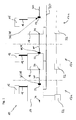
- FIG. 1 illustrated smoke-heat exhaust system 10 described in more detail and explained.
- the smoke-heat extraction system 10 comprises a plurality of smoke-heat extraction subsystems (hereinafter RWA subsystems), of which in FIG. 1 three RWA subsystems 12a, 12b and 12c are outlined.
- RWA subsystems smoke-heat extraction subsystems
- Each RWA subsystem 12a, 12b, 12c has a control device 14, by means of which in each case an actuator 16 can be controlled.
- the actuator 16 serves a non-illustrated air extraction device and / or to control a not shown air supply device accordingly.
- Each of the RWA subsystems 12a, 12b, 12c is used for ventilation or for smoke-heat protection of a respective building part, wherein the building parts in the FIG. 1 are indicated by vertically extending, dash-dotted lines.
- the control device 14 of each RWA subsystem 12a, 12b, 12c also provides the power supply for the respective associated actuator 16 in the illustrated example.
- the control device 14 is connected via a power line 18 to the actuator 16.
- Each control device 14 is designed to receive a control switching signal, on the basis of which the control device 14 drives the respectively assigned actuator 16 to a predetermined state.
- a smoke extraction operating state of the smoke-heat exhaust system in which the means of the actuators 16 controlled air exhaust devices and / or air supply means occupy a predetermined operating mode.
- the operating mode in the smoke extraction state can be adapted to the respective spatial conditions of the building secured by means of the smoke heat extraction system 10.
- Control parameters may be stored in the respective control devices 14, which define the operating mode which is assigned to the smoke extraction operating state.
- control devices 14 In order to supply all RWA subsystems 12a, 12b, 12c,... In the case of an alarm with an alarm switching signal and to cause the RWA subsystems 12a, 12b, 12c to assume the smoke extraction operating state, these are various control devices 14 via a control signal connection 20 connected to each other.
- the control devices 14 each have a signal line input 22 and a signal line output 24.
- the signal line input 22 is connected via a section of the control signal connection 20 to the signal line output 24 of an adjacent RWA subsystem.
- the signal line connection 20 is successively guided to the RWA subsystems 12a, 12b, 12c and connects them.
- the smoke-heat exhaust system 10 further comprises a monitoring device 26 which is designed to monitor the control signal connection 20 of the various SHE subsystems 12a, 12b, 12c for their functionality for transmitting switching signals (in particular the said alarm switching signals).
- the monitoring device 26 in each case includes the RWA subsystems 12a, 12b, 12c associated test devices 28. These are designed to check the electrical connections between the RWA subsystems 12a, 12b, 12c on their functioning, in particular a short circuit, a line break or a to recognize undesirable large resistance change (eg due to aging of contacts).
- the test apparatus 28 may be embodied, for example, in the manner of a conventional power-up line with line termination, as is known in the smoke detector technology.
- control signal connection 20 may be formed as a two-wire signal line, wherein in the region of the terminal 22 of a control device 14, the two wires of the signal line are connected to each other via a defined terminating resistor. A malfunction of the signal line connection 20 can then by changing the current through the Terminating resistor can be determined by means of the test device 28, for example, when a defined control potential concerns.
- the control devices 14 are designed in such a way that when the monitoring device 26 detects an impaired functionality of the control signal connection 20, an accident signal is generated.
- the accident signal is preferably transmitted to a central device, not shown, the smoke-heat exhaust system.
- a central device not shown, the smoke-heat exhaust system.
- all the control devices 14 of the various RWA subsystems are connected to a common signal bus 30, which communicates with said central device.
- the smoke and heat exhaust system 10 also has a plurality of tripping devices 32 (detectors), which are operated in case of fire to put the smoke and heat exhaust system 10 in its smoke control mode.
- tripping devices 32 are connected to one of the control devices 14. For example, depending on a triggering devices 32 in a corresponding part of the building be provided so that everywhere the message of a fire is possible.
- each SHE subsystem 12a, 12b, 12c may each have a ventilation controller. This serves to individually control the operating mode of each individual SHE subsystem 12a, 12b, 12c in a ventilation operating state of the smoke heat extraction system.
- the control device assigned to the detector 32 If, for example, one of the detectors 32 is actuated in the event of a fire, the control device assigned to the detector 32 generates an alarm switching signal. This is transmitted via the control signal connection 20 to the further RWA subsystems 12a, 12b, 12c,... And to their control devices 14.
- the control devices 14 are preferably designed in such a way that when such an alarm switching signal is received, an individual adjustment of the RWA subsystem via a ventilation switch is prevented. Rather, the control device 14 is designed such that when receiving an alarm switching signal, the actuator 16 is controlled such that the RWA subsystem is transferred in an operating mode associated with the smoke mode. It is conceivable, for example, that in case of alarm due to the transmission of the alarm switching signal all RWA subsystems are driven to generate a maximum ventilation performance.
- the control device 40 of the RWA subsystem 12b If, for example, the measurement of the test device 28 of the RWA subsystem 12b results in inadequate functionality of the control signal connection 20, for example in the region of the signal input 22 assigned to the RWA subsystem 12b, then the control device 40 of the RWA subsystem 12b generates an accident signal which is transmitted via the signal bus 30 can be transmitted to a central device or which activates a signaling device, such as alarm lamp, for emitting a warning signal. This makes it possible to initiate a suitable maintenance measure.
Landscapes
- Engineering & Computer Science (AREA)
- Chemical & Material Sciences (AREA)
- Combustion & Propulsion (AREA)
- Mechanical Engineering (AREA)
- General Engineering & Computer Science (AREA)
- Health & Medical Sciences (AREA)
- Public Health (AREA)
- Business, Economics & Management (AREA)
- Emergency Management (AREA)
- Air Conditioning Control Device (AREA)
- Respiratory Apparatuses And Protective Means (AREA)
- Fire Alarms (AREA)
Applications Claiming Priority (1)
| Application Number | Priority Date | Filing Date | Title |
|---|---|---|---|
| DE102013202443.6A DE102013202443A1 (de) | 2013-02-14 | 2013-02-14 | Verfahren zum Betreiben einer Rauch-Wärme-Abzugsanlage, sowie Rauch-Wärme-Abzugsanlage |
Publications (3)
| Publication Number | Publication Date |
|---|---|
| EP2767775A2 true EP2767775A2 (fr) | 2014-08-20 |
| EP2767775A3 EP2767775A3 (fr) | 2015-12-09 |
| EP2767775B1 EP2767775B1 (fr) | 2018-04-04 |
Family
ID=50101711
Family Applications (1)
| Application Number | Title | Priority Date | Filing Date |
|---|---|---|---|
| EP14154375.1A Active EP2767775B1 (fr) | 2013-02-14 | 2014-02-07 | Procédé de fonctionnement d'une installation d'extraction de fumées et de chaleur et installation d'extraction de fumées et de chaleur |
Country Status (2)
| Country | Link |
|---|---|
| EP (1) | EP2767775B1 (fr) |
| DE (1) | DE102013202443A1 (fr) |
Family Cites Families (8)
| Publication number | Priority date | Publication date | Assignee | Title |
|---|---|---|---|---|
| US3202079A (en) * | 1963-04-15 | 1965-08-24 | Burt Mfg Co | Quick release ventilators |
| DE2509496A1 (de) * | 1975-03-05 | 1976-09-09 | Dynamit Nobel Ag | Druckgaspatrone fuer brandschutzzwecke |
| DE4238342A1 (de) | 1992-08-26 | 1994-03-03 | Colt Int Holdings | Elektronische Unterstation als Steuereinheit für Einzelgeräte einer Anlage industrieller Heizungs- und Belüftungstechnik |
| DE19507407B4 (de) | 1994-03-04 | 2006-03-02 | Geze Gmbh | Einrichtung zur Betätigung und Überwachung von Rauch- und Wärmeabzugsöffnungen |
| US6776708B1 (en) * | 2003-01-27 | 2004-08-17 | Rick Daoutis | Smoke extraction system |
| DE102007011428B4 (de) | 2006-03-08 | 2011-08-25 | Heinrich Strunz GmbH, 95111 | Steuereinheit für eine Rauch- und Wärmeabzugsanlage eines Gebäudes |
| DE102007041383B4 (de) | 2007-08-31 | 2009-10-22 | K + G Pneumatik Gmbh | Rauch- und Wärmeabzugs- und Lüftungseinrichtung umfassend Rauch- und Wärmeabzugs- und Lüftungsgeräte mit jeweils einem motorischen Antrieb |
| GB2491903B (en) | 2011-06-18 | 2014-07-16 | Custom Electronics Ltd | Controlling smoke and heat evacuation and ventilation devices |
-
2013
- 2013-02-14 DE DE102013202443.6A patent/DE102013202443A1/de not_active Withdrawn
-
2014
- 2014-02-07 EP EP14154375.1A patent/EP2767775B1/fr active Active
Non-Patent Citations (1)
| Title |
|---|
| None |
Also Published As
| Publication number | Publication date |
|---|---|
| DE102013202443A1 (de) | 2014-08-14 |
| EP2767775B1 (fr) | 2018-04-04 |
| EP2767775A3 (fr) | 2015-12-09 |
Similar Documents
| Publication | Publication Date | Title |
|---|---|---|
| EP2804163B1 (fr) | Procédé et dispositif de détection des pannes dans des lignes de commande de systèmes de signalisation de danger et de systèmes de commande | |
| DE102008003799B4 (de) | Überwachungsvorrichtung für ein Meldesystem, Meldesystem und Verfahren zur Überwachung des Meldesystems | |
| EP2339557B1 (fr) | Dispositif de vérification pour installations d'alerte aux dangers | |
| EP2542946B1 (fr) | Équipement de contrôle d'une armoire électrique | |
| EP3441958B1 (fr) | Module de commande et de surveillance | |
| DE2857262A1 (de) | Gasmeldeanlage | |
| DE112013002661T5 (de) | Segment mit einer Fehlerschutzeinrichtung für ein zweidrahtiges, kombiniert verbundenes Energie- und Datennetzsystem | |
| DE112011100449B4 (de) | Verfahren zum Überprüfen eines Kurzschluss-Schutzsystems in einer Abzweigleitung sowie Diagnoseeinrichtung zum Durchführen des Verfahrens | |
| EP3704048A1 (fr) | Dispositif de surveillance de sécurité destiné à surveiller des états relatifs à la sécurité dans une installation de transport de personnes ainsi que procédé destiné à faire fonctionner ce dernier | |
| EP2277154A1 (fr) | Dispositif de surveillance destiné à surveiller le fonctionnement d'un système de signalisation, système de signalisation et procédé de surveillance | |
| EP2169645A1 (fr) | Contrôle des lignes d'alerte d'une installation d'alerte au danger | |
| EP1855261B1 (fr) | Procédé et dispositif destinés à la surveillance de perturbations sur une ligne d'avertissement d'une installation d'avertissement d'incendie | |
| DE102008028631B4 (de) | Leitungsüberwachung von Rauchschaltern | |
| EP2767775B1 (fr) | Procédé de fonctionnement d'une installation d'extraction de fumées et de chaleur et installation d'extraction de fumées et de chaleur | |
| EP1197936B2 (fr) | Système d'alarme | |
| EP0809361B1 (fr) | Dispositif électronique de commutation et circuit pour la surveillance d'une installation technique | |
| EP2520988B1 (fr) | Dispositif de surveillance de systèmes de surveillance de réseaux électriques | |
| EP3617114A1 (fr) | Procédé et dispositif de surveillance permettant de surveiller un dérailleur de sécurité dans une installation d'ascenseur | |
| DE112011101763T5 (de) | Fehlerschutzschaltung für eine IEC-61158-Feldbus-Abzweigleitung und Verfahren zu deren Anwendung | |
| EP3376485B1 (fr) | Unité d'émission de signal à canal de retour intégré | |
| DE20205249U1 (de) | Elektromotorische Antriebsanordnung mit Erstfehlersicherheitssystem | |
| EP2479733A1 (fr) | Surveillance de conduite d'interrupteurs de fumée | |
| EP0503122B1 (fr) | Arrangement pour commuter des lignes primaires en cas de perturbations | |
| DE102010052080B4 (de) | Haussignalanlage und Verfahren zum Betreiben einer solchen | |
| DE2646426B2 (de) | Feuerloschanlage |
Legal Events
| Date | Code | Title | Description |
|---|---|---|---|
| PUAI | Public reference made under article 153(3) epc to a published international application that has entered the european phase |
Free format text: ORIGINAL CODE: 0009012 |
|
| 17P | Request for examination filed |
Effective date: 20140207 |
|
| AK | Designated contracting states |
Kind code of ref document: A2 Designated state(s): AL AT BE BG CH CY CZ DE DK EE ES FI FR GB GR HR HU IE IS IT LI LT LU LV MC MK MT NL NO PL PT RO RS SE SI SK SM TR |
|
| RIN1 | Information on inventor provided before grant (corrected) |
Inventor name: ANDRASCHKO, GUENTHER Inventor name: YILDIRIM, CETIN |
|
| PUAL | Search report despatched |
Free format text: ORIGINAL CODE: 0009013 |
|
| AK | Designated contracting states |
Kind code of ref document: A3 Designated state(s): AL AT BE BG CH CY CZ DE DK EE ES FI FR GB GR HR HU IE IS IT LI LT LU LV MC MK MT NL NO PL PT RO RS SE SI SK SM TR |
|
| RIC1 | Information provided on ipc code assigned before grant |
Ipc: F24F 11/00 20060101AFI20151104BHEP Ipc: A62C 2/06 20060101ALI20151104BHEP |
|
| R17P | Request for examination filed (corrected) |
Effective date: 20160511 |
|
| RBV | Designated contracting states (corrected) |
Designated state(s): AL AT BE BG CH CY CZ DE DK EE ES FI FR GB GR HR HU IE IS IT LI LT LU LV MC MK MT NL NO PL PT RO RS SE SI SK SM TR |
|
| GRAP | Despatch of communication of intention to grant a patent |
Free format text: ORIGINAL CODE: EPIDOSNIGR1 |
|
| STAA | Information on the status of an ep patent application or granted ep patent |
Free format text: STATUS: GRANT OF PATENT IS INTENDED |
|
| INTG | Intention to grant announced |
Effective date: 20171031 |
|
| GRAS | Grant fee paid |
Free format text: ORIGINAL CODE: EPIDOSNIGR3 |
|
| RIN1 | Information on inventor provided before grant (corrected) |
Inventor name: ANDRASCHKO, GUENTER Inventor name: YILDIRIM, CETIN |
|
| GRAA | (expected) grant |
Free format text: ORIGINAL CODE: 0009210 |
|
| STAA | Information on the status of an ep patent application or granted ep patent |
Free format text: STATUS: THE PATENT HAS BEEN GRANTED |
|
| AK | Designated contracting states |
Kind code of ref document: B1 Designated state(s): AL AT BE BG CH CY CZ DE DK EE ES FI FR GB GR HR HU IE IS IT LI LT LU LV MC MK MT NL NO PL PT RO RS SE SI SK SM TR |
|
| REG | Reference to a national code |
Ref country code: GB Ref legal event code: FG4D Free format text: NOT ENGLISH |
|
| REG | Reference to a national code |
Ref country code: CH Ref legal event code: EP |
|
| REG | Reference to a national code |
Ref country code: AT Ref legal event code: REF Ref document number: 986003 Country of ref document: AT Kind code of ref document: T Effective date: 20180415 |
|
| REG | Reference to a national code |
Ref country code: IE Ref legal event code: FG4D Free format text: LANGUAGE OF EP DOCUMENT: GERMAN |
|
| REG | Reference to a national code |
Ref country code: DE Ref legal event code: R096 Ref document number: 502014007809 Country of ref document: DE |
|
| REG | Reference to a national code |
Ref country code: CH Ref legal event code: NV Representative=s name: DREISS PATENTANWAELTE PARTG MBB, DE |
|
| REG | Reference to a national code |
Ref country code: NL Ref legal event code: MP Effective date: 20180404 |
|
| REG | Reference to a national code |
Ref country code: LT Ref legal event code: MG4D |
|
| PG25 | Lapsed in a contracting state [announced via postgrant information from national office to epo] |
Ref country code: NL Free format text: LAPSE BECAUSE OF FAILURE TO SUBMIT A TRANSLATION OF THE DESCRIPTION OR TO PAY THE FEE WITHIN THE PRESCRIBED TIME-LIMIT Effective date: 20180404 |
|
| PG25 | Lapsed in a contracting state [announced via postgrant information from national office to epo] |
Ref country code: FI Free format text: LAPSE BECAUSE OF FAILURE TO SUBMIT A TRANSLATION OF THE DESCRIPTION OR TO PAY THE FEE WITHIN THE PRESCRIBED TIME-LIMIT Effective date: 20180404 Ref country code: BG Free format text: LAPSE BECAUSE OF FAILURE TO SUBMIT A TRANSLATION OF THE DESCRIPTION OR TO PAY THE FEE WITHIN THE PRESCRIBED TIME-LIMIT Effective date: 20180704 Ref country code: SE Free format text: LAPSE BECAUSE OF FAILURE TO SUBMIT A TRANSLATION OF THE DESCRIPTION OR TO PAY THE FEE WITHIN THE PRESCRIBED TIME-LIMIT Effective date: 20180404 Ref country code: ES Free format text: LAPSE BECAUSE OF FAILURE TO SUBMIT A TRANSLATION OF THE DESCRIPTION OR TO PAY THE FEE WITHIN THE PRESCRIBED TIME-LIMIT Effective date: 20180404 Ref country code: LT Free format text: LAPSE BECAUSE OF FAILURE TO SUBMIT A TRANSLATION OF THE DESCRIPTION OR TO PAY THE FEE WITHIN THE PRESCRIBED TIME-LIMIT Effective date: 20180404 Ref country code: AL Free format text: LAPSE BECAUSE OF FAILURE TO SUBMIT A TRANSLATION OF THE DESCRIPTION OR TO PAY THE FEE WITHIN THE PRESCRIBED TIME-LIMIT Effective date: 20180404 Ref country code: NO Free format text: LAPSE BECAUSE OF FAILURE TO SUBMIT A TRANSLATION OF THE DESCRIPTION OR TO PAY THE FEE WITHIN THE PRESCRIBED TIME-LIMIT Effective date: 20180704 Ref country code: PL Free format text: LAPSE BECAUSE OF FAILURE TO SUBMIT A TRANSLATION OF THE DESCRIPTION OR TO PAY THE FEE WITHIN THE PRESCRIBED TIME-LIMIT Effective date: 20180404 |
|
| PG25 | Lapsed in a contracting state [announced via postgrant information from national office to epo] |
Ref country code: RS Free format text: LAPSE BECAUSE OF FAILURE TO SUBMIT A TRANSLATION OF THE DESCRIPTION OR TO PAY THE FEE WITHIN THE PRESCRIBED TIME-LIMIT Effective date: 20180404 Ref country code: LV Free format text: LAPSE BECAUSE OF FAILURE TO SUBMIT A TRANSLATION OF THE DESCRIPTION OR TO PAY THE FEE WITHIN THE PRESCRIBED TIME-LIMIT Effective date: 20180404 Ref country code: GR Free format text: LAPSE BECAUSE OF FAILURE TO SUBMIT A TRANSLATION OF THE DESCRIPTION OR TO PAY THE FEE WITHIN THE PRESCRIBED TIME-LIMIT Effective date: 20180705 Ref country code: HR Free format text: LAPSE BECAUSE OF FAILURE TO SUBMIT A TRANSLATION OF THE DESCRIPTION OR TO PAY THE FEE WITHIN THE PRESCRIBED TIME-LIMIT Effective date: 20180404 |
|
| PG25 | Lapsed in a contracting state [announced via postgrant information from national office to epo] |
Ref country code: PT Free format text: LAPSE BECAUSE OF FAILURE TO SUBMIT A TRANSLATION OF THE DESCRIPTION OR TO PAY THE FEE WITHIN THE PRESCRIBED TIME-LIMIT Effective date: 20180806 |
|
| REG | Reference to a national code |
Ref country code: DE Ref legal event code: R026 Ref document number: 502014007809 Country of ref document: DE |
|
| PLBI | Opposition filed |
Free format text: ORIGINAL CODE: 0009260 |
|
| PLAX | Notice of opposition and request to file observation + time limit sent |
Free format text: ORIGINAL CODE: EPIDOSNOBS2 |
|
| PG25 | Lapsed in a contracting state [announced via postgrant information from national office to epo] |
Ref country code: SK Free format text: LAPSE BECAUSE OF FAILURE TO SUBMIT A TRANSLATION OF THE DESCRIPTION OR TO PAY THE FEE WITHIN THE PRESCRIBED TIME-LIMIT Effective date: 20180404 Ref country code: EE Free format text: LAPSE BECAUSE OF FAILURE TO SUBMIT A TRANSLATION OF THE DESCRIPTION OR TO PAY THE FEE WITHIN THE PRESCRIBED TIME-LIMIT Effective date: 20180404 Ref country code: CZ Free format text: LAPSE BECAUSE OF FAILURE TO SUBMIT A TRANSLATION OF THE DESCRIPTION OR TO PAY THE FEE WITHIN THE PRESCRIBED TIME-LIMIT Effective date: 20180404 Ref country code: RO Free format text: LAPSE BECAUSE OF FAILURE TO SUBMIT A TRANSLATION OF THE DESCRIPTION OR TO PAY THE FEE WITHIN THE PRESCRIBED TIME-LIMIT Effective date: 20180404 Ref country code: DK Free format text: LAPSE BECAUSE OF FAILURE TO SUBMIT A TRANSLATION OF THE DESCRIPTION OR TO PAY THE FEE WITHIN THE PRESCRIBED TIME-LIMIT Effective date: 20180404 |
|
| 26 | Opposition filed |
Opponent name: AUMUELLER AUMATIC GMBH Effective date: 20190104 |
|
| PG25 | Lapsed in a contracting state [announced via postgrant information from national office to epo] |
Ref country code: SM Free format text: LAPSE BECAUSE OF FAILURE TO SUBMIT A TRANSLATION OF THE DESCRIPTION OR TO PAY THE FEE WITHIN THE PRESCRIBED TIME-LIMIT Effective date: 20180404 Ref country code: IT Free format text: LAPSE BECAUSE OF FAILURE TO SUBMIT A TRANSLATION OF THE DESCRIPTION OR TO PAY THE FEE WITHIN THE PRESCRIBED TIME-LIMIT Effective date: 20180404 |
|
| PG25 | Lapsed in a contracting state [announced via postgrant information from national office to epo] |
Ref country code: SI Free format text: LAPSE BECAUSE OF FAILURE TO SUBMIT A TRANSLATION OF THE DESCRIPTION OR TO PAY THE FEE WITHIN THE PRESCRIBED TIME-LIMIT Effective date: 20180404 |
|
| PLAF | Information modified related to communication of a notice of opposition and request to file observations + time limit |
Free format text: ORIGINAL CODE: EPIDOSCOBS2 |
|
| PLBP | Opposition withdrawn |
Free format text: ORIGINAL CODE: 0009264 |
|
| PLBB | Reply of patent proprietor to notice(s) of opposition received |
Free format text: ORIGINAL CODE: EPIDOSNOBS3 |
|
| PLBD | Termination of opposition procedure: decision despatched |
Free format text: ORIGINAL CODE: EPIDOSNOPC1 |
|
| REG | Reference to a national code |
Ref country code: DE Ref legal event code: R100 Ref document number: 502014007809 Country of ref document: DE |
|
| GBPC | Gb: european patent ceased through non-payment of renewal fee |
Effective date: 20190207 |
|
| PG25 | Lapsed in a contracting state [announced via postgrant information from national office to epo] |
Ref country code: MC Free format text: LAPSE BECAUSE OF FAILURE TO SUBMIT A TRANSLATION OF THE DESCRIPTION OR TO PAY THE FEE WITHIN THE PRESCRIBED TIME-LIMIT Effective date: 20180404 Ref country code: LU Free format text: LAPSE BECAUSE OF NON-PAYMENT OF DUE FEES Effective date: 20190207 |
|
| REG | Reference to a national code |
Ref country code: BE Ref legal event code: MM Effective date: 20190228 |
|
| REG | Reference to a national code |
Ref country code: IE Ref legal event code: MM4A |
|
| PG25 | Lapsed in a contracting state [announced via postgrant information from national office to epo] |
Ref country code: IE Free format text: LAPSE BECAUSE OF NON-PAYMENT OF DUE FEES Effective date: 20190207 Ref country code: GB Free format text: LAPSE BECAUSE OF NON-PAYMENT OF DUE FEES Effective date: 20190207 |
|
| PLBM | Termination of opposition procedure: date of legal effect published |
Free format text: ORIGINAL CODE: 0009276 |
|
| PG25 | Lapsed in a contracting state [announced via postgrant information from national office to epo] |
Ref country code: FR Free format text: LAPSE BECAUSE OF NON-PAYMENT OF DUE FEES Effective date: 20190228 Ref country code: BE Free format text: LAPSE BECAUSE OF NON-PAYMENT OF DUE FEES Effective date: 20190228 |
|
| 27C | Opposition proceedings terminated |
Effective date: 20191021 |
|
| PG25 | Lapsed in a contracting state [announced via postgrant information from national office to epo] |
Ref country code: TR Free format text: LAPSE BECAUSE OF FAILURE TO SUBMIT A TRANSLATION OF THE DESCRIPTION OR TO PAY THE FEE WITHIN THE PRESCRIBED TIME-LIMIT Effective date: 20180404 |
|
| REG | Reference to a national code |
Ref country code: DE Ref legal event code: R082 Ref document number: 502014007809 Country of ref document: DE |
|
| PG25 | Lapsed in a contracting state [announced via postgrant information from national office to epo] |
Ref country code: MT Free format text: LAPSE BECAUSE OF FAILURE TO SUBMIT A TRANSLATION OF THE DESCRIPTION OR TO PAY THE FEE WITHIN THE PRESCRIBED TIME-LIMIT Effective date: 20180404 |
|
| PG25 | Lapsed in a contracting state [announced via postgrant information from national office to epo] |
Ref country code: CY Free format text: LAPSE BECAUSE OF FAILURE TO SUBMIT A TRANSLATION OF THE DESCRIPTION OR TO PAY THE FEE WITHIN THE PRESCRIBED TIME-LIMIT Effective date: 20180404 |
|
| PG25 | Lapsed in a contracting state [announced via postgrant information from national office to epo] |
Ref country code: IS Free format text: LAPSE BECAUSE OF FAILURE TO SUBMIT A TRANSLATION OF THE DESCRIPTION OR TO PAY THE FEE WITHIN THE PRESCRIBED TIME-LIMIT Effective date: 20180804 |
|
| PG25 | Lapsed in a contracting state [announced via postgrant information from national office to epo] |
Ref country code: HU Free format text: LAPSE BECAUSE OF FAILURE TO SUBMIT A TRANSLATION OF THE DESCRIPTION OR TO PAY THE FEE WITHIN THE PRESCRIBED TIME-LIMIT; INVALID AB INITIO Effective date: 20140207 |
|
| PG25 | Lapsed in a contracting state [announced via postgrant information from national office to epo] |
Ref country code: MK Free format text: LAPSE BECAUSE OF FAILURE TO SUBMIT A TRANSLATION OF THE DESCRIPTION OR TO PAY THE FEE WITHIN THE PRESCRIBED TIME-LIMIT Effective date: 20180404 |
|
| P01 | Opt-out of the competence of the unified patent court (upc) registered |
Effective date: 20230509 |
|
| REG | Reference to a national code |
Ref country code: CH Ref legal event code: U11 Free format text: ST27 STATUS EVENT CODE: U-0-0-U10-U11 (AS PROVIDED BY THE NATIONAL OFFICE) Effective date: 20260301 |
|
| PGFP | Annual fee paid to national office [announced via postgrant information from national office to epo] |
Ref country code: DE Payment date: 20260218 Year of fee payment: 13 |
|
| PGFP | Annual fee paid to national office [announced via postgrant information from national office to epo] |
Ref country code: AT Payment date: 20260219 Year of fee payment: 13 |
|
| PGFP | Annual fee paid to national office [announced via postgrant information from national office to epo] |
Ref country code: CH Payment date: 20260301 Year of fee payment: 13 |