EP2767452A2 - Einrichtung zur Anordnung eines Schwerpunktes eines Gerätewagens - Google Patents
Einrichtung zur Anordnung eines Schwerpunktes eines Gerätewagens Download PDFInfo
- Publication number
- EP2767452A2 EP2767452A2 EP14155200.0A EP14155200A EP2767452A2 EP 2767452 A2 EP2767452 A2 EP 2767452A2 EP 14155200 A EP14155200 A EP 14155200A EP 2767452 A2 EP2767452 A2 EP 2767452A2
- Authority
- EP
- European Patent Office
- Prior art keywords
- base plate
- support arm
- support arms
- trolley according
- equipment
- Prior art date
- Legal status (The legal status is an assumption and is not a legal conclusion. Google has not performed a legal analysis and makes no representation as to the accuracy of the status listed.)
- Granted
Links
- 230000005484 gravity Effects 0.000 title description 9
- 238000006073 displacement reaction Methods 0.000 description 3
- 238000002674 endoscopic surgery Methods 0.000 description 2
- 230000006978 adaptation Effects 0.000 description 1
- 238000005452 bending Methods 0.000 description 1
- 238000005553 drilling Methods 0.000 description 1
- 238000001802 infusion Methods 0.000 description 1
Images


Classifications
-
- B—PERFORMING OPERATIONS; TRANSPORTING
- B62—LAND VEHICLES FOR TRAVELLING OTHERWISE THAN ON RAILS
- B62B—HAND-PROPELLED VEHICLES, e.g. HAND CARTS OR PERAMBULATORS; SLEDGES
- B62B3/00—Hand carts having more than one axis carrying transport wheels; Steering devices therefor; Equipment therefor
- B62B3/02—Hand carts having more than one axis carrying transport wheels; Steering devices therefor; Equipment therefor involving parts being adjustable, collapsible, attachable, detachable or convertible
-
- B—PERFORMING OPERATIONS; TRANSPORTING
- B62—LAND VEHICLES FOR TRAVELLING OTHERWISE THAN ON RAILS
- B62B—HAND-PROPELLED VEHICLES, e.g. HAND CARTS OR PERAMBULATORS; SLEDGES
- B62B5/00—Accessories or details specially adapted for hand carts
-
- B—PERFORMING OPERATIONS; TRANSPORTING
- B62—LAND VEHICLES FOR TRAVELLING OTHERWISE THAN ON RAILS
- B62B—HAND-PROPELLED VEHICLES, e.g. HAND CARTS OR PERAMBULATORS; SLEDGES
- B62B2206/00—Adjustable or convertible hand-propelled vehicles or sledges
- B62B2206/02—Adjustable or convertible hand-propelled vehicles or sledges adjustable in length or width
-
- B—PERFORMING OPERATIONS; TRANSPORTING
- B62—LAND VEHICLES FOR TRAVELLING OTHERWISE THAN ON RAILS
- B62B—HAND-PROPELLED VEHICLES, e.g. HAND CARTS OR PERAMBULATORS; SLEDGES
- B62B2301/00—Wheel arrangements; Steering; Stability; Wheel suspension
- B62B2301/05—Details of the attachment of the wheel assembly to the chassis
-
- B—PERFORMING OPERATIONS; TRANSPORTING
- B62—LAND VEHICLES FOR TRAVELLING OTHERWISE THAN ON RAILS
- B62B—HAND-PROPELLED VEHICLES, e.g. HAND CARTS OR PERAMBULATORS; SLEDGES
- B62B2301/00—Wheel arrangements; Steering; Stability; Wheel suspension
- B62B2301/10—Adjusting the position of the wheel axles to increase stability
Definitions
- the invention relates to a trolley with a support frame, which has at least one storage area for receiving equipment and a base plate, wherein on the base plate provided with roller feet support arms are mounted.
- Such equipment trolleys are known in particular in the medical field in various embodiments.
- the equipment cart usually have a support frame with different storage areas and / or drawers, which serve to accommodate a variety of equipment, such as pumps, instruments and light sources.
- the trolleys are often equipped with swiveling holding arms for monitors, over which, for example, the surgeon in endoscopic surgery can follow the operation.
- the trolley must be designed to be movable for mobile use and have a high degree of stability and steadiness. To increase the stability against tilting, it is known to arrange the center of gravity of the equipment cart as far as possible by an appropriate arrangement of the equipment to be transported.
- a shift in emphasis of a provided for example with a pivotable arm for a monitor equipment cart can be counteracted insufficiently with the extendable support arms.
- the invention has the object , a trolley of the type mentioned in such a way that it ensures the highest level of stability and tipping stability.
- the solution to this problem is inventively characterized in that at least one support arm in the horizontal plane of the base plate is extensible and displaceable on the base plate can be fixed.
- Displaceable means that the support arm can be moved in a direction other than the direction in which it is extendable relative to the base plate. In particular, it can be partially or completely detached from the base plate, and in the horizontal plane at another point of the base plate or at another angle to the base plate be attached to this again.
- all support arms in the horizontal plane of the base plate are extendable and displaceable on the base plate and beyond the support arms are independently and individually extendable and relocatable to target the support arms to improve the stability and stability to be able to adjust, for example, the cramped space in an operating room can be considered.
- the extendability of the support arms can be accomplished, for example, by the telescopic design of the support arms.
- the at least one support arm is continuously extendable and displaceable on the base plate can be fixed in order to allow a particularly sensitive adjustment of the support arms to the changed center of gravity of the equipment cart.
- the at least one support arm in predetermined latching steps extendable and displaceable on the base plate can be fixed.
- a bolt is fixed so that the at least one support arm is pivotally mounted about the bolt to the base plate.
- the setting of the at least one support arm on the base plate in its respective position advantageously takes place in a device carriage designed according to the invention via bolts which can be inserted into corresponding bores in the base plate and in the support arm.
- the support arm By providing a plurality of holes in the base plate and in the support arm at different locations, the support arm can be set in different positions and different degrees pulled out on the base plate.
- slots on the support arm or the base plate of the support arm can advantageously be continuously variable with the help of the bolt to the base plate connected.
- this can for example be provided with a thread on which a nut can be screwed to attach the support arm to the base plate.
- one or more holes on the support arm and / or the base plate may be provided with an internal thread into which a bolt provided with a matching external thread can be screwed. In this way, the support arm can be easily and quickly released from the base plate and fixed elsewhere.
- the base plate consists of two spaced-apart and mutually parallel plates, wherein the support arms are mounted between the two plates of the base plate.
- the plates can have a great variety of distances from each other.
- the distance may correspond substantially to the thickness of a support arm.
- This has the advantage that the support arm is held securely between the plates of the base plate. Due to the additional provision of lateral guides, between which the support arm is inserted between the plates, a secure alignment of the support arm can be ensured. It may be provided at different positions laterally on or between the plates such guides to set the one or more support arms as needed at different locations on the base plate can.
- the invention proposes that the gap between the two plates of the base plate as an additional receiving space for equipment, especially for heavy system components, such as transformers, is available.
- roller feet are arranged on the free from the base plate free front ends of the support arms and that the support arms are formed starting from the bearing point of the roller feet in the direction of the base plate to stepwise angled downward.
- the inventive bending of the support arms is formed down so that the support arms are mounted approximately at the level of the horizontal axis of rotation of the roller feet on the base plate, whereby the center of gravity of the equipment cart is further shifted down and get the roller feet higher tipping.
- Illustration Fig. 1 shows a front perspective view of a trolley 1, which consists essentially of a support frame 2 with parallel to each other and one above the other on the support frame 2 arranged storage areas 3 and a lower base plate 4, wherein on the base plate 4 with roller feet 5 provided support arms 6 are mounted.
- the storage areas 3 are used to hold a variety of equipment 7, such as instruments, infusion pumps and the like.
- a pivotable support arm 8 is arranged, which serves to receive a monitor over which, for example, in endoscopic surgery, the surgeon can monitor and track the operation.
- the equipment cart 1 Since the equipment cart 1 is designed to be movable by means of the roller feet 5 for mobile use, the equipment cart 1 must have a high degree of stability and stability against tilting.
- the stability and tilt stability of the equipment cart 1 can be achieved in the illustrated embodiments by increasing the footprint of the equipment cart 1, including at least one stocked with a roller 5 support arm 6 in the horizontal plane of the base plate 4 is extendable and displaceable on the base plate 4 can be fixed.
- the shape of the base plate 4 and the number of provided with the roller feet 5 support arms 6 may vary from embodiment to embodiment. Ultimate for the improvement of stability and stability against tilting is the ability to enlarge or adjust the footprint of the trolley 1 by pulling and moving the position of the support arms 6 and thus also the roller feet 5 in the horizontal plane of the base plate 4.
- each individual provided with a Rollenfuß 5 support arm 6 can specifically targeted a possible displacement of the center of gravity of the equipment cart 1, for example by pivoting the equipped with a monitor support arm 8 at the upper end of the support frame 2, counteracted.
- each support arm 6 also ensures that, for example, based on the limited space in an operating room a maximum of stability and stability can be guaranteed.
- the base plate 4 each consist of two parallel and spaced apart superposed plates 9, wherein between the plates 9, a gap 10 is formed, which serves for example for the storage of the support arms 6.
- the distance between the two plates 9 substantially corresponds to the thickness of a support arm 6.
- this is arranged on the edge of the base plate 4 in a surrounding guide.
- roller feet 5 are arranged at the remote from the base plate 4 free front ends of the support arms 6 and that the support arms 6, starting from the bearing point of the roller feet 5 in the direction of the Base plate 4 are formed to step-shaped downwards angled so that the support arms 6 are mounted approximately at the level of the horizontal axis of rotation 11 of the roller feet 5 on the base plate 4.
- the center of gravity of the equipment cart 1 can be further shifted downwards that the gap 10 between the two plates 9 of the base plate 4 as an additional receiving space for equipment, especially for the relatively heavy transformers operated for safety reasons with low or low voltage devices, is usable.
- the extension and displacement of the support arms 6 in the horizontal plane of the base plate 4 is an example of the pictures Fig. 2 and 4 refer to.
- the support arms 6 in their respective position on the base plate 4
- the holes 13, for example, an internal thread and the bolts 12 have a matching external thread for fixing the bolt 12 in the holes 13.
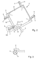
- Fig. 2 is shown at a corner of the base plate 4, between which positions a support arm 6 in this embodiment of the base plate 4 is adjustable, namely between a wide and completely shifted to the left position (solid line) and the inserted and completely shifted to the right position (dashed Line).
- a support arm 6 by pulling out of the base plate 4 and fixing with a bolt 12, it is also possible, the support arms 6 telescopically, so nestled and pulled apart, or screwed in a threaded section and expedischraubbar to design.
- the support arms 6 are pivotally mounted on the base plate 4 as a bolt 12 which can be fixed on the base plate-side free end of the support arms 6.
- the radial length of the support arms 6 during pivoting about the pin 12 is always the same.
- the radial extension of the support arms 6 can take place via a telescopic or screw-type design.
- the illustration Fig. 5 shows a section of a support arm 6, as in the embodiment according to Fig. 4 can be used.
- the bolt 12 is fixedly disposed on the base plate 4 fixable free end of the support arm 6 and is inserted into the corresponding bore 13 in the base plate 4 so that the support arm 6 is pivotable about this bolt 12.
- the bore 13 in the support arm 6 is used when fixing the support arm 6 in the respective pivoted position relative to the base plate 4 for receiving a bolt inserted into a bore of the base plate 4 12th
- equipment cart 1 is characterized in that the equipped with the roller feet 5 support arms 6 are not only extendable in the horizontal plane of the base plate 4, but also in the horizontal plane of the base plate 4 can be moved to the way to create the footprint of the equipment cart 1 targeted to increase so that the increase in footprint can be made exactly where, for example, by swinging a support arm 8, the focus of the equipment cart 1 was shifted unfavorably.
Landscapes
- Engineering & Computer Science (AREA)
- Chemical & Material Sciences (AREA)
- Combustion & Propulsion (AREA)
- Transportation (AREA)
- Mechanical Engineering (AREA)
- Handcart (AREA)
Abstract
Description
- Die Erfindung betrifft einen Gerätewagen mit einem Traggestell, das mindestens einen Ablagebereich zur Aufnahme von Gerätschaften sowie eine Grundplatte aufweist, wobei an der Grundplatte mit Rollenfüßen versehene Tragarme gelagert sind.
- Derartige Gerätewagen sind insbesondere im medizinischen Bereich in verschiedenen Ausführungsformen bekannt. Die Gerätewagen weisen in der Regel ein Traggestell mit verschiedenen Ablagebereichen und/oder Schubfächern auf, die zur Aufnahme verschiedenster Gerätschaften, wie beispielsweise Pumpen, Instrumenten und Lichtquellen dienen. Zusätzlich sind die Gerätewagen häufig mit verschwenkbaren Haltearmen für Monitore ausgerüstet, über die beispielsweise der Operateur bei der endoskopischen Chirurgie die Operation verfolgen kann.
- Die Gerätewagen müssen für einen mobilen Einsatz verfahrbar ausgebildet sein und ein hohes Maß an Standsicherheit und Kippsicherheit aufweisen. Zur Erhöhung der Kippsicherheit ist es bekannt, den Schwerpunkt der Gerätewagen durch eine entsprechende Anordnung der zu transportierenden Gerätschaften möglichst weit unten anzuordnen.
- Aus der
DE 298 01 799 U1 ist ein gattungsgemäßer Gerätewagen bekannt. Zur Erhöhung der Standsicherheit sind die Tragarme der Rollenfüße bei diesem bekannten Gerätewagen ausziehbar ausgebildet. Durch die Ausziehbarkeit der Tragarme lässt sich zwar die Standfläche des Gerätewagens vergrößern, jedoch nur in die vorgegebenen Richtungen der fest mit der Grundplatte verbundenen Tragarme. - Einer Schwerpunktverlagerung eines beispielsweise mit einem verschwenkbaren Haltearm für einen Monitor versehenen Gerätewagens kann mit den ausziehbaren Tragarmen nur unzureichend entgegengewirkt werden.
- Davon ausgehend liegt der Erfindung die Aufgabe zugrunde, einen Gerätewagen der eingangs genannten Art so auszugestalten, dass dieser ein Höchstmaß an Standsicherheit und Kippstabilität gewährleistet.
- Die Lösung dieser Aufgabenstellung ist erfindungsgemäß dadurch gekennzeichnet, dass mindestens ein Tragarm in der horizontalen Ebene der Grundplatte ausziehbar und verlagerbar an der Grundplatte festlegbar ist.
- Durch die Möglichkeit, einen mit einem Rollenfuß ausgestatteten Tragarm nicht nur in der horizontalen Ebene der Grundplatte relativ zu dieser auszuziehen, also das Ende des Tragarms, das den Rollenfuß trägt, weiter von der Grundplatte wegzuziehen, sondern den Tragarm auch horizontal in der Ebene der Grundplatte verlagern zu können, besteht erstmalig die Möglichkeit, die Standfläche des Gerätewagens gezielt so zu vergrößern oder anzupassen, dass die Vergrößerung und Anpassung der Standfläche genau dort vorgenommen werden kann, wo, beispielsweise durch Ausschwenken eines Haltearms, der Schwerpunkt des Gerätewagens ungünstig verlagert wurde. Verlagerbar bedeutet, dass der Tragarm auch in einer anderen Richtung als der Richtung, in der er ausziehbar ist, relativ zur Grundplatte bewegt werden kann. Insbesondere kann er von der Grundplatte teilweise oder vollständig gelöst, und in der horizontalen Ebene an anderer Stelle der Grundplatte oder in einem anderen Winkel zur Grundplatte wieder an dieser befestigt werden.
- Gemäß einer bevorzugten Ausführungsform der Erfindung wird vorgeschlagen, dass alle Tragarme in der horizontalen Ebene der Grundplatte ausziehbar und verlagerbar an der Grundplatte festlegbar sind und darüber hinaus die Tragarme unabhängig voneinander und individuell ausziehbar und verlagerbar sind, um zur Verbesserung der Standsicherheit und Kippsicherheit die Tragarme gezielt einstellen zu können, wobei beispielsweise auch die beengten Platzverhältnisse in einem Operationssaal berücksichtigt werden können.
- Die Ausziehbarkeit der Tragarme kann beispielsweise auch durch die teleskopierbare Ausgestaltung der Tragarme bewerkstelligt werden.
- Mit einer praktischen Ausführungsform der Erfindung wird vorgeschlagen, dass der mindestens eine Tragarm stufenlos ausziehbar und verlagerbar an der Grundplatte festlegbar ist, um eine besonders feinfühlige Anpassung der Tragarme an die veränderte Schwerpunktlage des Gerätewagens zu ermöglichen.
- Gemäß einer alternativen Ausführungsform der Erfindung wird vorgeschlagen, dass der mindestens eine Tragarm in vorgegebenen Rastschritten ausziehbar und verlagerbar an der Grundplatte festlegbar ist.
- Weiterhin wird mit der Erfindung vorgeschlagen, dass am grundplattenseitigen freien Ende des mindestens einen Tragarms ein Bolzen so festlegbar ist, dass der mindestens eine Tragarm um den Bolzen verschwenkbar an der Grundplatte gelagert ist. Diese Art der Ausgestaltung erlaubt auf besonders einfache Art und Weise eine seitliche Verlagerung des jeweiligen Tragarms durch bloßes Verschwenken um den Schwenkbolzen.
- Das Festlegen des mindestens einen Tragarms an der Grundplatte in seiner jeweiligen Position erfolgt bei einem erfindungsgemäß ausgebildeten Gerätewagen vorteilhafterweise über Bolzen, die in korrespondierende Bohrungen in der Grundplatte und im Tragarm einsetzbar sind.
- Durch das Vorsehen mehrerer Bohrungen in der Grundplatte und im Tragarm an unterschiedlichen Stellen kann der Tragarm in verschiedenen Positionen und verschieden weit ausgezogen an der Grundplatte festgelegt werden.
Durch das Vorsehen von Langlöchern am Tragarm oder der Grundplatte kann der Tragarm vorteilhafterweise auch stufenlos verstellbar mit Hilfe der Bolzen mit der Grundplatte verbunden werden. Um den Bolzen im Langloch zu sichern, kann dieser beispielsweise mit einem Gewinde versehen sein, auf das zur Befestigung des Tragarms an der Grundplatte eine Schraubenmutter aufschraubbar ist. Alternativ können eine oder mehrere Bohrungen am Tragarm und / oder der Grundplatte mit einem Innengewinde versehen sein, in das ein mit einem passenden Außengewinde versehener Bolzen einschraubbar ist. Auf diese Weise kann der Tragarm leicht und schnell von der Grundplatte gelöst und an anderer Stelle wieder befestigt werden. - Mit einer praktischen Ausführungsform der Erfindung wird vorgeschlagen, dass die Grundplatte aus zwei voneinander beabstandeten und parallel zueinander angeordneten Platten besteht, wobei die Tragarme zwischen den beiden Platten der Grundplatte gelagert sind.
- Dabei können die Platten verschiedenste Abstände zueinander aufweisen. Vorteilhafterweise kann der Abstand im Wesentlichen der Dicke eines Tragarms entsprechen. Dies hat den Vorteil, dass der Tragarm sicher zwischen den Platten der Grundplatte gehalten wird. Durch das zusätzliche Vorsehen seitlicher Führungen, zwischen die der Tragarm zwischen den Platten eingeschoben wird, kann auch eine sichere Ausrichtung des Tragarms gewährleistet werden. Es können an verschiedenen Positionen seitlich an oder zwischen den Platten solche Führungen vorgesehen sein, um den oder die Tragarme nach Bedarf an verschiedenen Stellen an der Grundplatte festlegen zu können.
- Zur Erhöhung der Kippstabilität ist es vorteilhaft, den Schwerpunkt des Gerätewagens möglichst tief anzuordnen. Hierzu wird erfindungsgemäß vorgeschlagen, dass der Zwischenraum zwischen den beiden Platten der Grundplatte als zusätzlicher Aufnahmeraum für Gerätschaften, insbesondere für schwere Systemkomponenten, wie Transformatoren, nutzbar ist.
- Schließlich wird mit der Erfindung vorgeschlagen, dass die Rollenfüße an den von der Grundplatte entfernten freien vorderen Enden der Tragarme angeordnet sind und dass die Tragarme ausgehend von der Lagerstelle der Rollenfüße in Richtung auf die Grundplatte zu stufenförmig nach unten abgewinkelt ausgebildet sind.
- Vorteilhafterweise ist die erfindungsgemäße Abwinklung der Tragarme nach unten so ausgebildet, dass die Tragarme in etwa auf Höhe der horizontalen Drehachse der Rollenfüße an der Grundplatte gelagert sind, wodurch der Schwerpunkt des Gerätewagens weiter nach unten verlagert wird und auch die Rollenfüße eine höhere Kippsicherheit erhalten.
- Weitere Merkmale und Vorteile der Erfindung ergeben sich anhand der zugehörigen Zeichnungen, in denen mehrere Ausführungsbeispiele eines erfindungsgemäßen Gerätewagens nur beispielhaft dargestellt sind, ohne die Erfindung auf diese Ausführungsbeispiele zu beschränken. In den Zeichnungen zeigt:
- Fig. 1
- eine schematische perspektivische Vorderansicht eines erfindungsgemäßen Gerätewagens;
- Fig. 2
- eine schematische Darstellung einer ersten Ausführungsform der Grundplatte eines Gerätewagens gemäß
Fig. 1 ; - Fig. 3
- eine vergrößerte Ansicht des Details III gemäß
Fig.2 ; - Fig. 4
- eine Darstellung gemäß
Fig. 2 , jedoch eine zweite Ausführungsform darstellend und - Fig. 5
- eine vergrößerte Detailansicht eines Tragarms.
- Abbildung
Fig. 1 zeigt eine perspektivisch dargestellte Vorderansicht eines Gerätewagens 1, der im Wesentlichen aus einem Traggestell 2 mit parallel zueinander und übereinander am Traggestell 2 angeordneten Ablagebereichen 3 sowie einer unteren Grundplatte 4 besteht, wobei an der Grundplatte 4 mit Rollenfüßen 5 versehene Tragarme 6 gelagert sind. - Die Ablagebereiche 3 dienen zur Aufnahme verschiedenster Gerätschaften 7, wie beispielsweise Instrumenten, Infusionspumpen und dergleichen. Am oberen Ende des Traggestells 2 ist ein verschwenkbarer Haltearm 8 angeordnet, der zur Aufnahme eines Monitors dient, über den beispielsweise bei der endoskopischen Chirurgie der Operateur die Operation überwachen und verfolgen kann.
- Da der Gerätewagen 1 mittels der Rollenfüße 5 für einen mobilen Einsatz verfahrbar ausgebildet ist, muss der Gerätwagen 1 ein hohes Maß an Standsicherheit und Kippsicherheit aufweisen.
- Die Standsicherheit und Kippsicherheit des Gerätewagens 1 kann bei den dargestellten Ausführungsbeispielen durch eine Vergrößerung der Standfläche des Gerätewagens 1 erzielt werden, wozu mindestens ein mit einem Rollenfuß 5 bestückter Tragarm 6 in der horizontalen Ebene der Grundplatte 4 ausziehbar und verlagerbar an der Grundplatte 4 festlegbar ist.
- Bei den in den Abbildungen
Fig. 1 ,2 und4 dargestellten Ausführungsformen sind alle Tragarme 6 unabhängig voneinander individuell ausziehbar und verlagerbar an der Grundplatte 4 festlegbar. - Die Form der Grundplatte 4 sowie die Anzahl der mit den Rollenfüßen 5 versehenen Tragarme 6 können von Ausführungsform zu Ausführungsform variieren. Endscheidend für die Verbesserung der Standsicherheit und Kippsicherheit ist die Möglichkeit, durch das Herausziehen und Verlagern der Position der Tragarme 6 und somit auch der Rollenfüße 5 in der horizontalen Ebene der Grundplatte 4 die Standfläche des Gerätewagens 1 zu vergrößern oder anzupassen.
- Durch das gezielte Verstellen jedes einzelnen mit einem Rollenfuß 5 versehenen Tragarms 6 kann ganz gezielt einer möglichen Verlagerung des Schwerpunktes des Gerätewagens 1, beispielsweise durch das Verschwenken des mit einem Monitor bestückten Haltearms 8 am oberen Ende des Traggestells 2, entgegengewirkt werden.
- Die individuelle Einstellbarkeit eines jeden Tragarms 6 gewährleistet auch, dass beispielsweise auch bezogen auf die beengten Platzverhältnisse in einem Operationssaal ein Höchstmaß an Standfestigkeit und Kippsicherheit gewährleistet werden kann.
- Bei den dargestellten Ausführungsbeispielen besteht die Grundplatte 4 jeweils aus zwei parallel und mit Abstand zueinander übereinander angeordneten Platten 9, wobei zwischen den Platten 9 ein Zwischenraum 10 ausgebildet ist, der beispielsweise zur Lagerung der Tragarme 6 dient. Beim in
Fig. 4 dargestellten Ausführungsbeispiel entspricht der Abstand der beiden Platten 9 im Wesentlichen der Dicke eines Tragarms 6. Zur verbesserten Sicherung des Tragarms 6 zwischen den Platten 9 ist dieser am Rand der Grundplatte 4 in einer ihn umgebenden Führung angeordnet. - Um die Kippsicherheit eines Gerätewagens 1 zu erhöhen, ist es allgemein bekannt, den Schwerpunkt des Gerätewagens 1 möglichst tief anzuordnen.
- Bei den dargestellten Ausführungsformen eines Gerätewagens 1 wird dies, wie insbesondere aus
Fig. 3 ersichtlich, unter anderem dadurch erzielt, dass die Rollenfüße 5 an den von der Grundplatte 4 entfernten freien vorderen Enden der Tragarme 6 angeordnet sind und dass die Tragarme 6 ausgehend von der Lagerstelle der Rollenfüße 5 in Richtung auf die Grundplatte 4 zu stufenförmig nach unten abgewinkelt ausgebildet sind, so dass die Tragarme 6 in etwa auf Höhe der horizontalen Drehachse 11 der Rollenfüße 5 an der Grundplatte 4 gelagert sind. - Weiterhin kann der Schwerpunkt des Gerätewagens 1 dadurch weiter nach unten verlagert werden, dass der Zwischenraum 10 zwischen den beiden Platten 9 der Grundplatte 4 als zusätzlicher Aufnahmeraum für Gerätschaften, insbesondere für die relativ schweren Transformatoren der aus Sicherheitsgründen mit Nieder- bzw. Kleinspannung betriebenen Geräte, nutzbar ist.
- Das Ausziehen und Verlagern der Tragarme 6 in der horizontalen Ebene der Grundplatte 4 ist beispielhaft den Abbildungen
Fig. 2 und4 zu entnehmen. - Das Festlegen des mindestens einen der Tragarme 6 an der Grundplatte 4 in seiner jeweiligen Position erfolgt über Bolzen 12, die in korrespondierende Bohrungen 13 in der Grundplatte 4 und den Tragarmen 6 einsetzbar sind. Alternativ zur Ausgestaltung als Bohrung 13 ist es auch möglich, die Aufnahme für die Bolzen 12 an den Tragarmen 6 als Langlöcher auszubilden.
- Alternativ zur Verwendung von Bolzen 12 zum Fixieren der Tragarme 6 in ihrer jeweiligen Lage an der Grundplatte 4 ist es selbstverständlich auch möglich, die Tragarme über Schraubverbindungen an der Grundplatte 4 festzulegen. Hierfür können die Bohrungen 13 beispielsweise ein Innengewinde und die Bolzen 12 ein passendes Außengewinde zur Befestigung der Bolzen 12 in den Bohrungen 13 aufweisen.
- In
Fig. 2 ist an einer Ecke der Grundplatte 4 dargestellt, zwischen welchen Positionen ein Tragarm 6 bei dieser Ausführungsform der Grundplatte 4 verstellbar ist, nämlich zwischen einer weit ausgezogenen und ganz nach links verlagerten Position (durchgezogene Linie) und der eingeschobenen und ganz nach rechts verlagerten Position (gestrichelte Linie). - Alternativ zum Verlängern eines Tragarms 6 durch Herausziehen aus der Grundplatte 4 und Fixieren mit einem Bolzen 12 ist es auch möglich, die Tragarme 6 teleskopierbar, also ineinanderschiebbar und auseinanderziehbar, oder über eine Gewindestrecke hereinschraubbar und herausschraubbar auszugestalten.
- Bei der in
Fig. 4 dargestellten Ausführungsform sind die Tragarme 6 als um einen am grundplattenseitigen freien Ende der Tragarme 6 festlegbaren Bolzen 12 verschwenkbar an der Grundplatte 4 gelagert. Im Falle der dargestellten kreisförmigen Grundplatte 4 bleibt die radiale Länge der Tragarme 6 beim Verschwenken um den Bolzen 12 stets gleich. Das radiale Verlängern der Tragarme 6 kann über eine teleskopierbare oder schraubbare Ausgestaltung erfolgen. - Die Abbildung
Fig. 5 zeigt ausschnittweise einen Tragarm 6, wie er bei der Ausgestaltung gemäßFig. 4 zum Einsatz kommen kann. In diesem Fall ist der Bolzen 12 fest am an der Grundplatte 4 festlegbaren freien Ende des Tragarms 6 angeordnet und wird in die entsprechende Bohrung 13 in der Grundplatte 4 so eingesetzt, dass der Tragarm 6 um diesen Bolzen 12 verschwenkbar ist. Die Bohrung 13 im Tragarm 6 dient beim Fixieren des Tragarms 6 in der jeweiligen verschwenkten Position relativ zur Grundplatte 4 zur Aufnahme eines in eine Bohrung der Grundplatte 4 eingesetzten Bolzens 12. - Der wie voranstehend beschrieben ausgebildete Gerätewagen 1 zeichnet sich dadurch aus, dass die mit den Rollenfüßen 5 ausgestatteten Tragarme 6 nicht nur in der horizontalen Ebene der Grundplatte 4 auszuziehbar sind, sondern auch in der horizontalen Ebene der Grundplatte 4 verlagert werden können, um so die Möglichkeit zu schaffen, die Standfläche des Gerätewagens 1 gezielt so zu vergrößern, dass die Vergrößerung der Standfläche genau dort vorgenommen werden kann, wo, beispielsweise durch Ausschwenken eines Haltearms 8, der Schwerpunkt des Gerätewagens 1 ungünstig verlagert wurde.
-
- 1
- Gerätewagen
- 2
- Traggestell
- 3
- Ablagebereich
- 4
- Grundplatte
- 5
- Rollenfuß
- 6
- Tragarm
- 7
- Gerätschaft
- 8
- Haltearm
- 9
- Platte
- 10
- Zwischenraum
- 11
- Drehachse
- 12
- Bolzen
- 13
- Bohrung
Claims (12)
- Gerätewagen mit einem Traggestell (2), das mindestens einen Ablagebereich (3) zur Aufnahme von Gerätschaften (7) sowie eine Grundplatte (4) aufweist, wobei an der Grundplatte (4) mit Rollenfüßen (5) versehene Tragarme (6) gelagert sind, dadurch gekennzeichnet,
dass mindestens ein Tragarm (6) in der horizontalen Ebene der Grundplatte (4) ausziehbar und verlagerbar an der Grundplatte (4) festlegbar ist. - Gerätewagen nach Anspruch 1, dadurch gekennzeichnet, dass alle Tragarme (6) in der horizontalen Ebene der Grundplatte (4) ausziehbar und verlagerbar an der Grundplatte (4) festlegbar sind.
- Gerätewagen nach Anspruch 1 oder 2, dadurch gekennzeichnet, dass die Tragarme (6) unabhängig voneinander und individuell ausziehbar und verlagerbar sind.
- Gerätewagen nach einem der Ansprüche 1 bis 3, dadurch gekennzeichnet, dass der mindestens eine Tragarm (6) stufenlos ausziehbar und verlagerbar an der Grundplatte (4) festlegbar ist.
- Gerätewagen nach einem der Ansprüche 1 bis 3, dadurch gekennzeichnet, dass der mindestens eine Tragarm (6) in vorgegebenen Rastschritten ausziehbar und verlagerbar an der Grundplatte (4) festlegbar ist.
- Gerätewagen nach einem der Ansprüche 1 bis 4, dadurch gekennzeichnet, dass am grundplattenseitigen freien Ende des mindestens einen Tragarms (6) ein Bolzen (12) so festlegbar ist, dass der mindestens eine Tragarm (6) um den Bolzen (12) verschwenkbar an der Grundplatte (4) gelagert ist.
- Gerätewagen nach einem der Ansprüche 1 bis 6, dadurch gekennzeichnet, dass das Festlegen des mindestens einen Tragarms (6) an der Grundplatte (4) in seiner jeweiligen Position über Bolzen (12) erfolgt, die in korrespondierende Bohrungen (13) in der Grundplatte (4) und des Tragarms (6) einsetzbar sind.
- Gerätewagen nach einem der Ansprüche 1 bis 7, dadurch gekennzeichnet, dass die Grundplatte (4) aus zwei voneinander beabstandeten und parallel zueinander angeordneten Platten (9) besteht.
- Gerätewagen nach Anspruch 8, dadurch gekennzeichnet, dass die Tragarme (6) zwischen den beiden Platten (9) der Grundplatte (4) gelagert sind.
- Gerätewagen nach Anspruch 8 oder 9, dadurch gekennzeichnet, dass der Zwischenraum (10) zwischen den beiden Platten (9) der Grundplatte (4) als zusätzlicher Aufnahmeraum für Gerätschaften, insbesondere für Transformatoren, nutzbar ist.
- Gerätewagen nach einem der Ansprüche 1 bis 10, dadurch gekennzeichnet, dass die Rollenfüße (5) an den von der Grundplatte (4) entfernten freien vorderen Enden der Tragarme (6) angeordnet sind und, dass die Tragarme (6) ausgehend von der Lagerstelle der Rollenfüße (5) in Richtung auf die Grundplatte (4) zu stufenförmig nach unten abgewinkelt ausgebildet sind.
- Gerätewagen nach Anspruch 11, dadurch gekennzeichnet, dass die Tragarme (6) in etwa auf Höhe der horizontalen Drehachse (11) der Rollenfüße (5) an der Grundplatte (4) gelagert sind.
Applications Claiming Priority (1)
| Application Number | Priority Date | Filing Date | Title |
|---|---|---|---|
| DE102013101525.5A DE102013101525A1 (de) | 2013-02-15 | 2013-02-15 | Gerätewagen |
Publications (3)
| Publication Number | Publication Date |
|---|---|
| EP2767452A2 true EP2767452A2 (de) | 2014-08-20 |
| EP2767452A3 EP2767452A3 (de) | 2016-10-05 |
| EP2767452B1 EP2767452B1 (de) | 2018-07-04 |
Family
ID=50112776
Family Applications (1)
| Application Number | Title | Priority Date | Filing Date |
|---|---|---|---|
| EP14155200.0A Active EP2767452B1 (de) | 2013-02-15 | 2014-02-14 | Einrichtung zur Anordnung eines Schwerpunktes eines Gerätewagens |
Country Status (3)
| Country | Link |
|---|---|
| US (1) | US9061694B2 (de) |
| EP (1) | EP2767452B1 (de) |
| DE (1) | DE102013101525A1 (de) |
Cited By (4)
| Publication number | Priority date | Publication date | Assignee | Title |
|---|---|---|---|---|
| CN104309656A (zh) * | 2014-09-28 | 2015-01-28 | 苏州市汉诺威升降台有限公司 | 一种手动载重液压推车 |
| ITUA20163153A1 (it) * | 2016-05-04 | 2017-11-04 | Carrello da spesa dotato di un cesto sollevabile. | |
| ITUA20163150A1 (it) * | 2016-05-04 | 2017-11-04 | Giacomo Lupi | Carrello allargabile. |
| WO2017191591A1 (en) * | 2016-05-04 | 2017-11-09 | Idee Retail Di Sergio Lupi & C. S.N.C. | Shopping trolley equipped with a liftable basket |
Families Citing this family (4)
| Publication number | Priority date | Publication date | Assignee | Title |
|---|---|---|---|---|
| CN106697024B (zh) * | 2017-03-08 | 2023-07-18 | 遵义医学院附属医院 | 一种方便搬运多道微量泵的设备 |
| US11033110B2 (en) * | 2018-06-01 | 2021-06-15 | Comfor Tek Seating Inc. | Chair caddie |
| CN110884549A (zh) * | 2018-10-18 | 2020-03-17 | 唐飞 | 一种基于光电距离监测的双轮车调节机构系统 |
| CN113232709A (zh) * | 2021-05-17 | 2021-08-10 | 东亚装饰股份有限公司 | 一种节能环保建筑板材固定装置 |
Citations (1)
| Publication number | Priority date | Publication date | Assignee | Title |
|---|---|---|---|---|
| DE29801799U1 (de) | 1998-02-03 | 1998-03-26 | Knürr-Mechanik für die Elektronik AG, 81829 München | Mobile Einrichtung |
Family Cites Families (10)
| Publication number | Priority date | Publication date | Assignee | Title |
|---|---|---|---|---|
| US115779A (en) * | 1871-06-06 | Improvement in sewing-machine casters | ||
| US1887067A (en) * | 1929-10-02 | 1932-11-08 | Colson Company | Piano truck |
| US5476432A (en) * | 1993-12-14 | 1995-12-19 | Dickens; Robert | Medical stroller |
| US5464243A (en) * | 1995-01-13 | 1995-11-07 | Deere & Company | Adjustable axle with shim structure |
| DE19819356B4 (de) | 1998-05-04 | 2004-09-02 | Rautec Rauschenberger Gmbh | Handgeführter Wagen |
| US6843625B2 (en) * | 2002-11-26 | 2005-01-18 | Htc Products, Inc. | Floor stop for a mobile base |
| US7478819B1 (en) * | 2008-03-27 | 2009-01-20 | International Business Machines Corporation | Forced extension caster assembly |
| US7988161B2 (en) * | 2009-01-14 | 2011-08-02 | Grk Manufacturing Co. | Piano dolly |
| US20100283227A1 (en) | 2009-03-23 | 2010-11-11 | Rubbermaid Commercial Products, Llc | Service cart |
| US8474835B1 (en) * | 2010-10-25 | 2013-07-02 | Remo J. Rossi | Mobile support cart for adjustable holding equipment |
-
2013
- 2013-02-15 DE DE102013101525.5A patent/DE102013101525A1/de not_active Withdrawn
-
2014
- 2014-02-14 US US14/180,926 patent/US9061694B2/en active Active
- 2014-02-14 EP EP14155200.0A patent/EP2767452B1/de active Active
Patent Citations (1)
| Publication number | Priority date | Publication date | Assignee | Title |
|---|---|---|---|---|
| DE29801799U1 (de) | 1998-02-03 | 1998-03-26 | Knürr-Mechanik für die Elektronik AG, 81829 München | Mobile Einrichtung |
Cited By (4)
| Publication number | Priority date | Publication date | Assignee | Title |
|---|---|---|---|---|
| CN104309656A (zh) * | 2014-09-28 | 2015-01-28 | 苏州市汉诺威升降台有限公司 | 一种手动载重液压推车 |
| ITUA20163153A1 (it) * | 2016-05-04 | 2017-11-04 | Carrello da spesa dotato di un cesto sollevabile. | |
| ITUA20163150A1 (it) * | 2016-05-04 | 2017-11-04 | Giacomo Lupi | Carrello allargabile. |
| WO2017191591A1 (en) * | 2016-05-04 | 2017-11-09 | Idee Retail Di Sergio Lupi & C. S.N.C. | Shopping trolley equipped with a liftable basket |
Also Published As
| Publication number | Publication date |
|---|---|
| US9061694B2 (en) | 2015-06-23 |
| DE102013101525A1 (de) | 2014-08-21 |
| US20140232079A1 (en) | 2014-08-21 |
| EP2767452A3 (de) | 2016-10-05 |
| EP2767452B1 (de) | 2018-07-04 |
Similar Documents
| Publication | Publication Date | Title |
|---|---|---|
| EP2767452B1 (de) | Einrichtung zur Anordnung eines Schwerpunktes eines Gerätewagens | |
| DE60012314T2 (de) | Warenschaustand | |
| DE102009040200B4 (de) | Transportvorrichtung für ein längliches Objekt | |
| DE102014104681B4 (de) | Operationstischsäule und Operationstisch mit einer derartigen Operationstischsäule | |
| DE102011017467B3 (de) | Traganordnung für Solarmodule | |
| EP3087866A1 (de) | Beschlag für einen eckschrank und eckschrank mit beschlag | |
| WO2010054836A2 (de) | Klemmhalterung | |
| DE202011109614U1 (de) | Sonnennachführungsvorrichtung für Solarpeneele | |
| DE102010004739A1 (de) | Vorrichtung zum Klemmen von Werkstücken auf einer Basis | |
| EP2037030A1 (de) | Transportwagen für Nadelbretter | |
| DE202004012298U1 (de) | Haushaltsgerät mit verschwenkbarem Anzeigeschirm | |
| EP2064972B1 (de) | Schrankauszug mit einem ausziehbaren Tragteil und an diesem befestigbarer Möbelfront | |
| DE102007038047A1 (de) | Kippvorrichtung | |
| EP2896320A1 (de) | Tischverlängerungsbeschlag für einen Tisch mit einer Tischplatte und einer Auszugplatte sowie Tisch mit einem Tischverlängerungsbeschlag | |
| DE202014000473U1 (de) | Beinstütze | |
| DE102009044220B4 (de) | Kamerawagen | |
| EP1875834A1 (de) | Haltvorrichtung für eine Stange und Möbel | |
| DE202017002570U1 (de) | Bildschirmstandeinrichtung | |
| DE102015002727B4 (de) | Vorrichtung zum Aufrichten am Boden liegender Personen | |
| DE10337523A1 (de) | Lithotripter | |
| DE102004020267A1 (de) | Haushaltsgerät mit verschwenkbarem Anzeigeschirm | |
| EP2789904A2 (de) | Transportable Leuchtvorrichtung mit Biegestäben | |
| WO2020094806A1 (de) | Chirurgische schaedelhaltevorrichtung | |
| DE202019100583U1 (de) | Arbeitstisch | |
| EP0281093A2 (de) | Geräteträger |
Legal Events
| Date | Code | Title | Description |
|---|---|---|---|
| PUAI | Public reference made under article 153(3) epc to a published international application that has entered the european phase |
Free format text: ORIGINAL CODE: 0009012 |
|
| 17P | Request for examination filed |
Effective date: 20140214 |
|
| AK | Designated contracting states |
Kind code of ref document: A2 Designated state(s): AL AT BE BG CH CY CZ DE DK EE ES FI FR GB GR HR HU IE IS IT LI LT LU LV MC MK MT NL NO PL PT RO RS SE SI SK SM TR |
|
| AX | Request for extension of the european patent |
Extension state: BA ME |
|
| PUAL | Search report despatched |
Free format text: ORIGINAL CODE: 0009013 |
|
| AK | Designated contracting states |
Kind code of ref document: A3 Designated state(s): AL AT BE BG CH CY CZ DE DK EE ES FI FR GB GR HR HU IE IS IT LI LT LU LV MC MK MT NL NO PL PT RO RS SE SI SK SM TR |
|
| AX | Request for extension of the european patent |
Extension state: BA ME |
|
| RIC1 | Information provided on ipc code assigned before grant |
Ipc: B62B 5/00 20060101ALI20160826BHEP Ipc: B62B 3/02 20060101AFI20160826BHEP |
|
| STAA | Information on the status of an ep patent application or granted ep patent |
Free format text: STATUS: REQUEST FOR EXAMINATION WAS MADE |
|
| R17P | Request for examination filed (corrected) |
Effective date: 20170329 |
|
| RBV | Designated contracting states (corrected) |
Designated state(s): AL AT BE BG CH CY CZ DE DK EE ES FI FR GB GR HR HU IE IS IT LI LT LU LV MC MK MT NL NO PL PT RO RS SE SI SK SM TR |
|
| STAA | Information on the status of an ep patent application or granted ep patent |
Free format text: STATUS: EXAMINATION IS IN PROGRESS |
|
| 17Q | First examination report despatched |
Effective date: 20170712 |
|
| RAP1 | Party data changed (applicant data changed or rights of an application transferred) |
Owner name: KARL STORZ SE & CO. KG |
|
| GRAP | Despatch of communication of intention to grant a patent |
Free format text: ORIGINAL CODE: EPIDOSNIGR1 |
|
| STAA | Information on the status of an ep patent application or granted ep patent |
Free format text: STATUS: GRANT OF PATENT IS INTENDED |
|
| INTG | Intention to grant announced |
Effective date: 20180321 |
|
| GRAS | Grant fee paid |
Free format text: ORIGINAL CODE: EPIDOSNIGR3 |
|
| GRAA | (expected) grant |
Free format text: ORIGINAL CODE: 0009210 |
|
| STAA | Information on the status of an ep patent application or granted ep patent |
Free format text: STATUS: THE PATENT HAS BEEN GRANTED |
|
| AK | Designated contracting states |
Kind code of ref document: B1 Designated state(s): AL AT BE BG CH CY CZ DE DK EE ES FI FR GB GR HR HU IE IS IT LI LT LU LV MC MK MT NL NO PL PT RO RS SE SI SK SM TR |
|
| REG | Reference to a national code |
Ref country code: GB Ref legal event code: FG4D Free format text: NOT ENGLISH |
|
| REG | Reference to a national code |
Ref country code: CH Ref legal event code: EP |
|
| REG | Reference to a national code |
Ref country code: AT Ref legal event code: REF Ref document number: 1014178 Country of ref document: AT Kind code of ref document: T Effective date: 20180715 |
|
| REG | Reference to a national code |
Ref country code: IE Ref legal event code: FG4D Free format text: LANGUAGE OF EP DOCUMENT: GERMAN |
|
| REG | Reference to a national code |
Ref country code: DE Ref legal event code: R096 Ref document number: 502014008711 Country of ref document: DE |
|
| REG | Reference to a national code |
Ref country code: NL Ref legal event code: MP Effective date: 20180704 |
|
| REG | Reference to a national code |
Ref country code: LT Ref legal event code: MG4D |
|
| PG25 | Lapsed in a contracting state [announced via postgrant information from national office to epo] |
Ref country code: NL Free format text: LAPSE BECAUSE OF FAILURE TO SUBMIT A TRANSLATION OF THE DESCRIPTION OR TO PAY THE FEE WITHIN THE PRESCRIBED TIME-LIMIT Effective date: 20180704 |
|
| PG25 | Lapsed in a contracting state [announced via postgrant information from national office to epo] |
Ref country code: NO Free format text: LAPSE BECAUSE OF FAILURE TO SUBMIT A TRANSLATION OF THE DESCRIPTION OR TO PAY THE FEE WITHIN THE PRESCRIBED TIME-LIMIT Effective date: 20181004 Ref country code: BG Free format text: LAPSE BECAUSE OF FAILURE TO SUBMIT A TRANSLATION OF THE DESCRIPTION OR TO PAY THE FEE WITHIN THE PRESCRIBED TIME-LIMIT Effective date: 20181004 Ref country code: RS Free format text: LAPSE BECAUSE OF FAILURE TO SUBMIT A TRANSLATION OF THE DESCRIPTION OR TO PAY THE FEE WITHIN THE PRESCRIBED TIME-LIMIT Effective date: 20180704 Ref country code: IS Free format text: LAPSE BECAUSE OF FAILURE TO SUBMIT A TRANSLATION OF THE DESCRIPTION OR TO PAY THE FEE WITHIN THE PRESCRIBED TIME-LIMIT Effective date: 20181104 Ref country code: GR Free format text: LAPSE BECAUSE OF FAILURE TO SUBMIT A TRANSLATION OF THE DESCRIPTION OR TO PAY THE FEE WITHIN THE PRESCRIBED TIME-LIMIT Effective date: 20181005 Ref country code: LT Free format text: LAPSE BECAUSE OF FAILURE TO SUBMIT A TRANSLATION OF THE DESCRIPTION OR TO PAY THE FEE WITHIN THE PRESCRIBED TIME-LIMIT Effective date: 20180704 Ref country code: CZ Free format text: LAPSE BECAUSE OF FAILURE TO SUBMIT A TRANSLATION OF THE DESCRIPTION OR TO PAY THE FEE WITHIN THE PRESCRIBED TIME-LIMIT Effective date: 20180704 Ref country code: FI Free format text: LAPSE BECAUSE OF FAILURE TO SUBMIT A TRANSLATION OF THE DESCRIPTION OR TO PAY THE FEE WITHIN THE PRESCRIBED TIME-LIMIT Effective date: 20180704 Ref country code: PL Free format text: LAPSE BECAUSE OF FAILURE TO SUBMIT A TRANSLATION OF THE DESCRIPTION OR TO PAY THE FEE WITHIN THE PRESCRIBED TIME-LIMIT Effective date: 20180704 Ref country code: SE Free format text: LAPSE BECAUSE OF FAILURE TO SUBMIT A TRANSLATION OF THE DESCRIPTION OR TO PAY THE FEE WITHIN THE PRESCRIBED TIME-LIMIT Effective date: 20180704 |
|
| PG25 | Lapsed in a contracting state [announced via postgrant information from national office to epo] |
Ref country code: LV Free format text: LAPSE BECAUSE OF FAILURE TO SUBMIT A TRANSLATION OF THE DESCRIPTION OR TO PAY THE FEE WITHIN THE PRESCRIBED TIME-LIMIT Effective date: 20180704 Ref country code: ES Free format text: LAPSE BECAUSE OF FAILURE TO SUBMIT A TRANSLATION OF THE DESCRIPTION OR TO PAY THE FEE WITHIN THE PRESCRIBED TIME-LIMIT Effective date: 20180704 Ref country code: AL Free format text: LAPSE BECAUSE OF FAILURE TO SUBMIT A TRANSLATION OF THE DESCRIPTION OR TO PAY THE FEE WITHIN THE PRESCRIBED TIME-LIMIT Effective date: 20180704 Ref country code: HR Free format text: LAPSE BECAUSE OF FAILURE TO SUBMIT A TRANSLATION OF THE DESCRIPTION OR TO PAY THE FEE WITHIN THE PRESCRIBED TIME-LIMIT Effective date: 20180704 |
|
| REG | Reference to a national code |
Ref country code: DE Ref legal event code: R097 Ref document number: 502014008711 Country of ref document: DE |
|
| PG25 | Lapsed in a contracting state [announced via postgrant information from national office to epo] |
Ref country code: EE Free format text: LAPSE BECAUSE OF FAILURE TO SUBMIT A TRANSLATION OF THE DESCRIPTION OR TO PAY THE FEE WITHIN THE PRESCRIBED TIME-LIMIT Effective date: 20180704 Ref country code: RO Free format text: LAPSE BECAUSE OF FAILURE TO SUBMIT A TRANSLATION OF THE DESCRIPTION OR TO PAY THE FEE WITHIN THE PRESCRIBED TIME-LIMIT Effective date: 20180704 |
|
| PLBE | No opposition filed within time limit |
Free format text: ORIGINAL CODE: 0009261 |
|
| STAA | Information on the status of an ep patent application or granted ep patent |
Free format text: STATUS: NO OPPOSITION FILED WITHIN TIME LIMIT |
|
| PG25 | Lapsed in a contracting state [announced via postgrant information from national office to epo] |
Ref country code: DK Free format text: LAPSE BECAUSE OF FAILURE TO SUBMIT A TRANSLATION OF THE DESCRIPTION OR TO PAY THE FEE WITHIN THE PRESCRIBED TIME-LIMIT Effective date: 20180704 Ref country code: SM Free format text: LAPSE BECAUSE OF FAILURE TO SUBMIT A TRANSLATION OF THE DESCRIPTION OR TO PAY THE FEE WITHIN THE PRESCRIBED TIME-LIMIT Effective date: 20180704 Ref country code: SK Free format text: LAPSE BECAUSE OF FAILURE TO SUBMIT A TRANSLATION OF THE DESCRIPTION OR TO PAY THE FEE WITHIN THE PRESCRIBED TIME-LIMIT Effective date: 20180704 |
|
| 26N | No opposition filed |
Effective date: 20190405 |
|
| PG25 | Lapsed in a contracting state [announced via postgrant information from national office to epo] |
Ref country code: SI Free format text: LAPSE BECAUSE OF FAILURE TO SUBMIT A TRANSLATION OF THE DESCRIPTION OR TO PAY THE FEE WITHIN THE PRESCRIBED TIME-LIMIT Effective date: 20180704 |
|
| REG | Reference to a national code |
Ref country code: CH Ref legal event code: PL |
|
| PG25 | Lapsed in a contracting state [announced via postgrant information from national office to epo] |
Ref country code: LU Free format text: LAPSE BECAUSE OF NON-PAYMENT OF DUE FEES Effective date: 20190214 Ref country code: MC Free format text: LAPSE BECAUSE OF FAILURE TO SUBMIT A TRANSLATION OF THE DESCRIPTION OR TO PAY THE FEE WITHIN THE PRESCRIBED TIME-LIMIT Effective date: 20180704 |
|
| REG | Reference to a national code |
Ref country code: BE Ref legal event code: MM Effective date: 20190228 |
|
| REG | Reference to a national code |
Ref country code: IE Ref legal event code: MM4A |
|
| PG25 | Lapsed in a contracting state [announced via postgrant information from national office to epo] |
Ref country code: CH Free format text: LAPSE BECAUSE OF NON-PAYMENT OF DUE FEES Effective date: 20190228 Ref country code: LI Free format text: LAPSE BECAUSE OF NON-PAYMENT OF DUE FEES Effective date: 20190228 |
|
| PG25 | Lapsed in a contracting state [announced via postgrant information from national office to epo] |
Ref country code: IE Free format text: LAPSE BECAUSE OF NON-PAYMENT OF DUE FEES Effective date: 20190214 |
|
| PG25 | Lapsed in a contracting state [announced via postgrant information from national office to epo] |
Ref country code: BE Free format text: LAPSE BECAUSE OF NON-PAYMENT OF DUE FEES Effective date: 20190228 |
|
| PG25 | Lapsed in a contracting state [announced via postgrant information from national office to epo] |
Ref country code: TR Free format text: LAPSE BECAUSE OF FAILURE TO SUBMIT A TRANSLATION OF THE DESCRIPTION OR TO PAY THE FEE WITHIN THE PRESCRIBED TIME-LIMIT Effective date: 20180704 |
|
| REG | Reference to a national code |
Ref country code: AT Ref legal event code: MM01 Ref document number: 1014178 Country of ref document: AT Kind code of ref document: T Effective date: 20190214 |
|
| PG25 | Lapsed in a contracting state [announced via postgrant information from national office to epo] |
Ref country code: AT Free format text: LAPSE BECAUSE OF NON-PAYMENT OF DUE FEES Effective date: 20190214 |
|
| PG25 | Lapsed in a contracting state [announced via postgrant information from national office to epo] |
Ref country code: PT Free format text: LAPSE BECAUSE OF FAILURE TO SUBMIT A TRANSLATION OF THE DESCRIPTION OR TO PAY THE FEE WITHIN THE PRESCRIBED TIME-LIMIT Effective date: 20181105 Ref country code: MT Free format text: LAPSE BECAUSE OF FAILURE TO SUBMIT A TRANSLATION OF THE DESCRIPTION OR TO PAY THE FEE WITHIN THE PRESCRIBED TIME-LIMIT Effective date: 20180704 |
|
| PG25 | Lapsed in a contracting state [announced via postgrant information from national office to epo] |
Ref country code: CY Free format text: LAPSE BECAUSE OF FAILURE TO SUBMIT A TRANSLATION OF THE DESCRIPTION OR TO PAY THE FEE WITHIN THE PRESCRIBED TIME-LIMIT Effective date: 20180704 |
|
| PG25 | Lapsed in a contracting state [announced via postgrant information from national office to epo] |
Ref country code: HU Free format text: LAPSE BECAUSE OF FAILURE TO SUBMIT A TRANSLATION OF THE DESCRIPTION OR TO PAY THE FEE WITHIN THE PRESCRIBED TIME-LIMIT; INVALID AB INITIO Effective date: 20140214 |
|
| PG25 | Lapsed in a contracting state [announced via postgrant information from national office to epo] |
Ref country code: MK Free format text: LAPSE BECAUSE OF FAILURE TO SUBMIT A TRANSLATION OF THE DESCRIPTION OR TO PAY THE FEE WITHIN THE PRESCRIBED TIME-LIMIT Effective date: 20180704 |
|
| P01 | Opt-out of the competence of the unified patent court (upc) registered |
Effective date: 20230527 |
|
| PGFP | Annual fee paid to national office [announced via postgrant information from national office to epo] |
Ref country code: DE Payment date: 20250226 Year of fee payment: 12 |
|
| PGFP | Annual fee paid to national office [announced via postgrant information from national office to epo] |
Ref country code: FR Payment date: 20250224 Year of fee payment: 12 |
|
| PGFP | Annual fee paid to national office [announced via postgrant information from national office to epo] |
Ref country code: IT Payment date: 20250225 Year of fee payment: 12 Ref country code: GB Payment date: 20250218 Year of fee payment: 12 |