EP2767151A1 - Mähdrescherantriebssystem - Google Patents
Mähdrescherantriebssystem Download PDFInfo
- Publication number
- EP2767151A1 EP2767151A1 EP14151945.4A EP14151945A EP2767151A1 EP 2767151 A1 EP2767151 A1 EP 2767151A1 EP 14151945 A EP14151945 A EP 14151945A EP 2767151 A1 EP2767151 A1 EP 2767151A1
- Authority
- EP
- European Patent Office
- Prior art keywords
- engine
- clutch
- speed
- ecu
- combine harvester
- Prior art date
- Legal status (The legal status is an assumption and is not a legal conclusion. Google has not performed a legal analysis and makes no representation as to the accuracy of the status listed.)
- Granted
Links
- 230000008859 change Effects 0.000 claims description 5
- 230000004044 response Effects 0.000 claims description 4
- 239000000446 fuel Substances 0.000 description 16
- 230000005540 biological transmission Effects 0.000 description 13
- 238000000034 method Methods 0.000 description 13
- 238000003306 harvesting Methods 0.000 description 11
- 239000012530 fluid Substances 0.000 description 8
- 230000008569 process Effects 0.000 description 8
- 238000004140 cleaning Methods 0.000 description 5
- 239000000463 material Substances 0.000 description 5
- 230000006870 function Effects 0.000 description 4
- 241001124569 Lycaenidae Species 0.000 description 3
- 238000002485 combustion reaction Methods 0.000 description 3
- 230000002706 hydrostatic effect Effects 0.000 description 3
- 230000008878 coupling Effects 0.000 description 2
- 238000010168 coupling process Methods 0.000 description 2
- 238000005859 coupling reaction Methods 0.000 description 2
- 238000010586 diagram Methods 0.000 description 2
- 230000009347 mechanical transmission Effects 0.000 description 2
- 230000009286 beneficial effect Effects 0.000 description 1
- 244000038559 crop plants Species 0.000 description 1
- 230000003247 decreasing effect Effects 0.000 description 1
- 230000000694 effects Effects 0.000 description 1
- 230000008570 general process Effects 0.000 description 1
- 239000010903 husk Substances 0.000 description 1
- 230000003993 interaction Effects 0.000 description 1
- 239000002245 particle Substances 0.000 description 1
- 230000000284 resting effect Effects 0.000 description 1
- 238000004904 shortening Methods 0.000 description 1
- 239000010902 straw Substances 0.000 description 1
Images


Classifications
-
- A—HUMAN NECESSITIES
- A01—AGRICULTURE; FORESTRY; ANIMAL HUSBANDRY; HUNTING; TRAPPING; FISHING
- A01D—HARVESTING; MOWING
- A01D41/00—Combines, i.e. harvesters or mowers combined with threshing devices
- A01D41/12—Details of combines
- A01D41/127—Control or measuring arrangements specially adapted for combines
- A01D41/1274—Control or measuring arrangements specially adapted for combines for drives
Definitions
- the present inventions pertains to drive systems for combine harvesters.
- Combine harvesters are machines to engineered to travel through agricultural fields at harvest time harvesting crops. They typically include a self-propelled vehicle upon which a harvesting head is mounted. The harvesting head extends across the front of the combine harvester and severs the stalks of the crop plants close to the surface of the ground.
- the harvesting head severs at least a portion of the plants from the ground, gathers the severed portions together, and conveys them into the body of the combine harvester itself for further processing.
- the combine harvester performs three basic processing functions: threshing, separating, and cleaning.
- the combine harvester also stores the grain until it can be unloaded from the combine harvester.
- the threshing and separating are performed by a cylindrical rotor disposed inside a closely spaced concave.
- the concave is a hollow and generally cylindrical-shaped structure that surrounds the rotor.
- a narrow gap is provided between the rotor and the concave.
- the severed crop matter is introduced into this gap at a forward end of the rotor and concave.
- MOG material other than grain
- the frictional drag between the rotor and the concave is significant, particularly when the gap between the rotor and the concave is filled with crop material.
- the rotor rotates at a constant speed.
- the load on the engine changes, however, making it difficult to keep the rotor operating at a constant speed.
- the power required to rotate the rotor can increase substantially.
- a direct mechanical connection i.e. the power transmission path
- a fixed rotational speed ratio is provided between the engine and the rotor.
- the rotor and the engine run at constant relative speeds with respect to each other.
- the operator operates the combine at its maximum possible speed to harvest a crop as fast as possible.
- the engine is controlled to operate at a constant and (typically) high speed.
- the speed of the engine is typically around 2000 to 2200 RPM when the combine harvester is operating at full speed.
- a combine harvester drive system switches between two engine power curves of an isochronously governed engine when the engine load reaches a threshold load condition.
- a combine harvester drive system automatically changes the speed of the engine as a function of engine load, both to a higher and to a lower speed, while keeping the speed of the threshing rotor the same.
- a combine harvester has an engine coupled to a multiple speed gearbox, which in turn is coupled to a threshing rotor.
- the gearbox permits the engine to engage the threshing rotor in at least two distinct gear ratios.
- an electronic control unit automatically changes the gear ratio based upon a predetermined vehicle condition.
- This predetermined vehicle condition may include the load applied to the engine.
- This predetermined vehicle condition may include a calculation of engine operating efficiency.
- the gearbox includes a plurality of clutches, the plurality of clutches include a first clutch that is engaged when the gearbox is engaged in one of the two distinct gear ratios.
- the plurality of clutches include a second clutch that is engaged with the gearbox is engaged in another of the two distinct gear ratios.
- the combine harvester includes a plurality of drive wheels.
- the drive wheels are driven by a hydrostatic drive system.
- the hydrostatic drive system is driven by the engine through the gearbox.
- the combine harvester further includes drive members.
- the drive members are driven by the gearbox.
- the drive members are configured to engage a straw chopper and an unloading system.
- a combine harvester drive system comprises an engine, a governor coupled to the engine to control the speed of the engine based upon a speed signal, a first clutch coupled to the engine to be driven by the engine, a second clutch coupled to the engine in parallel to the first clutch to be driven by the engine, a threshing rotor coupled to the first clutch and the second clutch to be driven thereby, and an ECU coupled to the first clutch and the second clutch to selectively engage and disengage the first clutch and the second clutch, and coupled to the governor to transmit a speed command to the governor, and wherein the ECU is configured to engage one of the first clutch and the second clutch and to disengage the other of the first clutch and the second clutch when the engine reaches a first predetermined load level.
- the first clutch and the second clutch may be disposed inside a gearbox.
- the governor may be configured to isochronously control the engine over a range of operating loads.
- the governor may be configured to receive the speed signal from the ECU.
- the ECU may be configured to command one of the clutches to engage and to command another of the clutches to disengage, and to command the governor to change the speed of the engine by at least 200 RPM, at predetermined intervals such that the engaging, the disengaging, and the engine speed changing occur within a two second interval.
- the combine harvester drive system may further comprise an operator input device coupled to the ECU.
- the ECU may be configured to command the engagement of the first clutch, command the disengagement of the second clutch, and command the governor to decrease a speed of the engine upon operator manipulation of the operator input device.
- the ECU may be configured to command the disengagement of the first clutch, may command the engagement of the second clutch, and may command the governor to increase the speed of the engine upon operator manipulation of the operator input device.
- the ECU may be configured to automatically and periodically monitor an engine load condition.
- the ECU may be configured (1) to engage the second clutch and (2) to disengage the first clutch and (3) to transmit a first speed command to the governor commanding the governor to increase the engine speed, in response to the ECU determining that the engine load condition has exceeded a first threshold engine load condition.
- the first speed command to the governor may be a command to control the engine at a first speed even while the load fluctuates on the engine (i.e. isochronous governing of the engine speed).
- the ECU may be configured (1) to disengage the second clutch and (2) to engage the first clutch and (3) to transmit a second speed command to the governor to decrease the engine speed, in response to the ECU determining that the engine load condition has dropped below a second threshold engine load condition.
- the second speed command to the governor may be a command to control the engine at a second speed even while the load fluctuates on the engine (i.e. isochronous governing of the engine speed), the second speed being different from the third speed.
- the first engine load condition may be indicative of a higher engine load than the second engine load condition.
- the first speed command may represent and indicate an engine speed higher than an engine speed represented and indicated by second speed command.
- a method of operating a combine harvester drive system of a combine harvester having an engine controlled by a governor configured to operate the engine isochronously is provided, the combine harvester further having a threshing rotor coupled to the engine, the combine harvester further having first power transmission path coupling the engine to the threshing rotor in a first ratio of rotational speed of the engine and rotational speed of the threshing rotor, and a second power transmission path coupling the engine to the threshing rotor in a second ratio of rotational speed of the engine and rotational speed of the threshing rotor wherein the first ratio is different from the second ratio, and further wherein ECU is coupled to the governor, the method comprising the steps of:
- the method may further include a step of the ECU transmitting a first engine speed command to the governor substantially simultaneously with the step of switching from the first power transmission path to the second power transmission path.
- the method may further include the step of the ECU automatically and periodically determining whether the engine load condition is reached a second threshold engine load condition, and switching from the second power transmission path to the first power transmission path when the engine load condition reaches the second threshold engine load condition.
- the method may also include the step of transmitting a second engine speed command to the governor substantially simultaneously with the step of switching from the second power transmission path to the first power transmission path.
- a harvesting vehicle 100 includes a combine harvester 102 and a harvesting head 104.
- Harvesting head 104 is supported on the front of the combine harvester 102, resting upon and supported by a feederhouse 106 that is pivotally coupled to the front end of the combine harvester 102.
- Crop material severed by the harvesting head 104 is conveyed rearward through an inclined conveyor in the feederhouse 106 into the body of the combine harvester 102. Once inside the body of the combine harvester 102, the crop material is directed into a gap between a threshing rotor 108 and a concave 110.
- the concave 110 partially surrounds the threshing rotor.
- the threshing rotor 108 has threshing elements (not shown) that engage the crop material that is drawn between the threshing elements and the concave 110, and separate the grain from the MOG.
- the grain falls downward through apertures in the concave 110 into a cleaning shoe 112.
- a cleaning fan 114 is provided to blow air upward through screens in the cleaning shoe 112. This flow of air separates the grain from lighter MOG.
- the grain is permitted to fall downward through screens in the cleaning shoe 112 and onto the floor of the combine harvester 102.
- the lighter MOG is carried rearward, where it is ejected from the combine harvester 102 and is spread over the ground.
- the grain is carried upward by a transverse auger 116 and deposited in a grain tank 118.
- a grain cart or truck pulls alongside the combine and an unloading conveyor 120 (in this case, an auger disposed inside a tube) conveys the grain from the grain tank 118 into the grain cart or truck.
- the MOG that is separated from the grain by the interaction of the threshing rotor 108 and the concave 110 is carried to the rear of the threshing rotor 108 and concave 110 and is conveyed to a chopper 124.
- the chopper 124 chops the MOG into smaller particles and distributes them over the ground.
- An engine 126 is disposed in an upper rear portion of the combine harvester 102 in a position adjacent to the rear end of the threshing rotor 108.
- the engine 126 is coupled to and drives a gearbox 128, which in turn is coupled to and drives the threshing rotor 108, causing the threshing rotor 108 to rotate within the concave 110.
- the gearbox 128 includes a first drive member 130 and the second drive member 132 that are respectively coupled to and drive the chopper 124 and the unloading conveyor 120 byway of conventional mechanical transmission elements (not shown) such as hydraulic hoses, gears, shafts, pulleys and belts. These mechanical transmission elements have been removed for clarity of illustration.
- engine 126 is coupled to an input shaft 200 extending from gearbox 128.
- the threshing rotor 108 is coupled to and driven by an output shaft 202 which extends from the gearbox 128.
- a first output shaft 204 and a second output shaft 206 both extend from gearbox 128.
- the first output shaft 204 is coupled to and drives the first drive member 130.
- the second drive member 132 is coupled by a belt (not shown) to the unloading conveyor 120 and drives the unloading conveyor 120.
- the second output shaft 206 is coupled to and drives the second drive member 132.
- the second drive member 132 is coupled by a belt (not shown) to the chopper 124 and drives the chopper 124.
- An output shaft 208 extends from the gearbox 128 and is coupled to a hydrostatic drive system 210, which in turn is coupled to the drive wheels (the two front wheels in Figure 1 ) of the combine harvester 102.
- a gear 212 is fixed to the input shaft 200.
- the gear 212 is engaged to and drives a gear 214.
- the gear 214 is fixed to and drives the input shaft 216 of a hydraulic clutch 218.
- the hydraulic clutch 218 has an output shaft 220 that is coupled to and drives a gear 222.
- the gear 222 drives the gear 224.
- the gear 224 is fixed to and drives a shaft 226.
- the shaft 226 is fixed to and drives a gear 228.
- the gear 228 is engaged with and drives a gear 230.
- the gear 230 is fixed to and drives the output shaft 202.
- the shaft 226 is also fixed to and drives the second output shaft 206.
- the input shaft 200 is also fixed to and drives an input member 232 of a hydraulic clutch 234.
- the hydraulic clutch 234 has an output member 236 that is coupled to and drives the gear 224.
- the engine 126 can be coupled to the shaft 226 in a first gear ratio by engaging the hydraulic clutch 218 or the engine 126 can be coupled to the shaft 226 in a second gear ratio by engaging the hydraulic clutch 234.
- the first gear ratio and the second gear ratio are different.
- the engine can be operated at a first speed in the first gear ratio and at a second speed in the second gear ratio.
- the hydraulic clutch 218 and the hydraulic clutch 234 are hydraulic or "wet" clutches. They are engaged and disengaged by being filled with pressurized hydraulic fluid or by releasing pressurized hydraulic fluid from the clutches.
- an engine governor 300 (of the electronic type) is coupled to and controls the speed of the engine 126.
- the engine governor 300 is coupled to an electronic control unit (ECU) 302.
- the ECU 302 is coupled to an operator input device 304.
- the ECU 302 is also coupled to and operates a hydraulic valve 306.
- the hydraulic valve 306 is coupled to and receives hydraulic fluid under pressure from a hydraulic fluid source 308.
- the hydraulic valve 306 is also coupled to, and exhausts hydraulic fluid to, a hydraulic fluid reservoir 310.
- the hydraulic valve 306 controls the flow of hydraulic fluid both to and from the hydraulic clutch 218 and the hydraulic clutch 234.
- the ECU 302 is configured to signal the hydraulic valve 306 to conduct hydraulic fluid under pressure both to and from the hydraulic clutch 218 and the hydraulic clutch 234 under appropriate conditions determined by the control program that the ECU 302 executes and which is described in greater detail below.
- the engine governor 300 is configured to receive signals from the ECU 302 indicating a desired operating speed of the engine 126.
- the engine governor 300 is configured to automatically regulate the speed of the engine 126 to the speed of the engine 126 indicated by ECU 302.
- the engine governor 300 is also configured to transmit signals to the ECU 302 indicating the actual speed of the engine 126 and the load on the engine 126.
- the ECU 302 comprises a microprocessor 312, a random-access memory (RAM) 314, a read-only memory (ROM) 316, and a valve driver circuit 318.
- the microprocessor 312 is configured to execute a sequence of digital instructions that are stored in the read-only memory 316.
- the microprocessor 312 stores working values in the random-access memory 314 that the microprocessor 312 calculates during its programmed operation.
- the microprocessor 312 is configured to receive signals indicative of operator commands that are transmitted from the operator input device 304.
- the operator input device 304 is configured to be manipulated by the operator to generate these signals.
- the ECU 302 follows a sequence of digital instructions stored in the read-only memory 316. These instructions cause the ECU 302 to perform the steps shown in Figure 4 .
- the steps shown in Figure 4 are executed in a repeating cycle of instructions, each cycle of the instructions having a duration of between 10 and 250 ms before the instructions are repeated in the next cycle.
- step 400 the ECU 302 reads a speed signal, indicating the speed of the engine 126 and a load signal, indicating the load on the engine 126 from the engine governor 300.
- step 404 the ECU 302 determines whether the load on the engine 126 has climbed to or above a first predetermined threshold load value.
- step 404 If the load on the engine 126 has climbed to or above the first predetermined threshold load value as determined in step 404, the ECU 302 executes step 406, in which the ECU 302 signals the valve driver circuit 318 to disengage the hydraulic clutch 218 and to engage the hydraulic clutch 234 substantially simultaneously.
- the ECU 302 executes step 408 in which the ECU 302 signals the engine governor 300 to regulate the speed of the engine 126 at a first command speed.
- step 408 the ECU 302 loops again to step 402 and subsequently performs another cycle of the process.
- step 410 the ECU 302 determines whether the load on the engine 126 has fallen to or below a second predetermined threshold load value.
- step 412 the ECU 302 signals the valve driver circuit 318 to disengage the hydraulic clutch 234 and to engage the hydraulic clutch 218 substantially simultaneously.
- step 414 the ECU 302 signals the engine governor 300 to regulate the speed of the engine 126 at a second command speed that is less than the first command speed.
- step 414 the ECU 302 loops again to step 402 and repeats the process.
- the ECU 302 loops again to step 402 and repeats the process.
- FIG. 5 illustrates an alternative process executed by the ECU 302 in which the ECU 302 responds to the operator's manipulation of the operator input device 304.
- step 500 The process begins in step 500.
- step 502 the ECU 302 reads a signal from the operator input device 304. In step 504, the ECU 302 determines whether the operator has selected a high speed of rotation for the engine 126.
- step 506 the ECU 302 signals the valve driver circuit 318 to engage the hydraulic clutch 234 and to disengage the hydraulic clutch 218 substantially simultaneously (if it has not done so already in a previous processing loop).
- step 508 the ECU 302 signals the engine governor 300 to regulate the speed of the engine 126 at a high speed of rotation (a first command speed).
- step 508 the ECU 302 loops again to the step 502 and repeats the cycle.
- step 510 the ECU 302 continues on to step 510 in which it signals the valve driver circuit 318 to engage the hydraulic clutch 218 and to disengage the hydraulic clutch 234 substantially simultaneously (if it has not done so already in a previous processing loop).
- the ECU 302 then continues on to step 512 in which the ECU 302 signals the engine governor 300 to regulate the speed of the engine 126 at a low speed of rotation (i.e. at a second command speed lower than the first command speed).
- the ECU 302 After executing the step 512, the ECU 302 loops again to the step 502 and repeats the process.
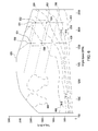
- Figure 6 illustrates a torque/power curve for a typical internal combustion engine such as the engine 126.
- the torque in Newton-meters
- the engine speed in revolutions per minute
- Each point underneath the uppermost curve of this plot is a point at which the engine can be operated.
- the point on the curve at which the engine 126 operates is determined by the engine governor 300.
- the engine governor 300 receives commands from the ECU 302 that indicate the desired speed at which the engine 126 should operate.
- the engine governor 300 is configured to operate the engine 126 as long as possible at a commanded speed. This is called isochronous operation, and is typical of the governors on vehicles such as the combine harvester 102.
- An equal load line 600 illustrates a constant power of 200 kW. At any point along this line, at the corresponding engine speed and the indicated torque, the engine 126 produces 200 kW of power.
- An equal load line 602 illustrates a constant power of 300 kW. At any point on this line, at the indicated engine speed and the indicated torque, the engine 126 produces 300 kW of power.
- An equal load line 604 illustrates a constant power of 400 kW. At any point on this line, at the indicated engine speed and the indicated torque, the engine 126 produces 400 kW of power.
- Figure 6 is divided into several regions outlined with dashed lines.
- the engine 126 In the innermost region, bounded by a boundary line 606 (a dashed line), the engine 126 operates at a brake specific fuel consumption (alternatively "BSFC", an inverse measure of fuel efficiency) of greater than 200 g/kW-hr. In other words, for every kilowatt hour of work the engine does in this region, the engine 126 will consume 200gms of fuel. In the operating region bounded by the boundary line 606 and a boundary line 608 (a dashed line), the engine 126 operates at a brake specific fuel consumption of between 210 and 200 g/kW-hr.
- BSFC brake specific fuel consumption
- the engine 126 is operating at a BSFC of between 220 and 210 g/kW-hr.
- the BSFC is between 230 and 220 g/kW-hr region.
- the BSFC is between 240 and 230 g/kW-hr.
- the BSFC is between 250 and 240 g/kW-hr.
- the BSFC is between 260 and 250 g/kW-hr region.
- the highest engine efficiency is achieved in the region bounded by the boundary line 606. The farther one travels away from this region, the lower the engine efficiency. For high fuel efficiency, the engine should be operated as close as possible to the region bounded by the boundary line 606.
- the engine 126 operates most efficiently at its lowest possible BSFC.
- the equal load line 600, the equal load line 602, and the equal load line 604 indicate that the engine 126 can be operated at many different speeds to produce the same power and substantially the same torque.
- an engine such as the engine 126 would be operated isochronously at a speed of about 2100-2200 RPM.
- This line is called the "operating curve" of the engine and is controlled by the engine governor.
- the engine governor Although it is often called a “curve” it is a line of substantially constant engine speed.
- the operator sets the speed of the engine as fast as it will go without stalling--approximately 2100-2200 RPM.
- the governor maintains the speed substantially constant while increasing the power output and torque of the engine.
- the engine governor 300 maintains the speed of engine 126 constant by increasing the fuel supplied to the engine 126 as the load on the engine increases.
- the traditional maximum speed engine operating curve (shown as the isochronous operating curve 622) does not define the most efficient range of operating points under all working conditions. For example, if the engine 126 is only providing 200 kW of power, one can follow the 200 kW line (the equal load line 600) from the place it intersects isochronous operating curve 622 to the left and see that another engine operating curve, (shown in Figure 6 as the isochronous operating curve 628) could provide the same power, with greater torque, and greater fuel efficiency (as indicated by its overall lower BSFC).
- the engine will almost immediately stop. If the engine is operating on the operating curve indicated by isochronous operating curve 628 and the load on the engine abruptly increases, many operators will not be able to respond quickly enough to prevent the engine from stalling. On the other hand, if the engine is operated on isochronous operating curve 622, and the load on the engine abruptly increases, many operators will have enough time to reduce the load on the engine before the engine stalls.
- isochronously governed engines are typically operated at a higher-speed engine operating curve (e.g. along the isochronous operating curve 622) than at a more fuel-efficient lower-speed engine operating curve (e.g. along the isochronous operating curve 628).
- a higher-speed engine operating curve e.g. along the isochronous operating curve 622
- a more fuel-efficient lower-speed engine operating curve e.g. along the isochronous operating curve 628.
- the ECU 302 will determine that the engine load has reached a high load threshold in step 404, shown as the operating point 631 in Figure 6 .
- the ECU 302 then engages hydraulic clutch 234, disengages the hydraulic clutch 218, and issues a higher engine speed operating command to the engine governor 300, which shifts the engine operating curve from isochronous operating curve 628 to isochronous operating curve 622.
- the load on the engine will fluctuate up and down with the governor maintaining the engine speed along the line segment between the operating point 632 and the operating point 634. Eventually, however, the load on the engine will fall below a minimum load (determined in step 410 in Figure 4 ) shown in Figure 6 as operating point 634.
- the ECU 302 will then swap the clutch engagement (i.e. hydraulic clutch 234 will be disengaged, and hydraulic clutch 218 will be engaged) and ECU 302 will automatically issue a speed command to the engine governor 300 that is reduced by 300 RPM (i.e. from 2100 to 1800 RPM).
- engine governor 300 is an isochronous governor
- the new speed command shifts the operating curve of engine 126 from operating at the operating point 634 on the operating curve indicated by isochronous operating curve 622 to operating at the operating point 636 on the operating curve indicated by isochronous operating curve 628.
- a dead band is provided between the 2 shift points.
- the engine operating curve shifts from the lower speed curve (isochronous operating curve 628 to the higher-speed curve (isochronous operating curve 622) at a power level of about 400 kW.
- the engine operating curve shifts from the higher-speed curve (isochronous operating curve 622) to the lower speed curve (isochronous operating curve 628) at a power level substantially lower, around 275 kW. Requiring a shift at two different power levels substantially reduces the amount of time the clutches spend engaging and disengaging and permits the engine to operate isochronously at one of the operating curves or the other for a significant proportion of the combine harvester operating time.
- the speed command and clutch downshift shift point in step 404 (the operating point 631) is preferably at least 100 kW higher than the speed command and clutch upshift shift point in step 410 (the operating point 634).
- the engagement and disengagement of the hydraulic clutch 218 and the hydraulic clutch 234 can be calibrated such that the entire shift from the disengagement of one clutch to the engagement of the other can occur within an interval of less than one second.
- Engine governors such as engine governor 300 are also capable of changing the fuel to the engine equally fast. To avoid stalling the vehicle when the clutches engage and disengage, and when the governor changes the engine operating curve, the two clutches and the engine speed change should be calibrated to all occur within a two second interval of time. Alternately they can be calibrated to all occur within a one second interval of time. Alternately they can be calibrated to all occur within a 750 ms interval of time. Shortening the interval in which all of the actions occur will necessitate regular calibration of the clutches by the ECU 302.
- the example provided above discusses a single ECU 302. While this arrangement is possible, it is also possible to have multiple ECUs each providing some of the functions described above and that are connected together in a network of ECUs.
- one ECU 302 is coupled to one or both of the hydraulic clutch 218 and the hydraulic clutch 234.
- Yet another ECU 302 is coupled to the operator input device 304. All of these ECUs are joined together in a network such as a CANbus in accordance with the SAE J 1939 standard.
- Each of these ECUs 302 are individually configured to collectively provide the functions of controlling the governor and selectively engaging and disengaging the hydraulic clutch 218 and the hydraulic clutch 234 in the manner described herein to shift between two isochronous engine operating curves. Therefore the term "ECU" as used herein refers to either one ECU or a plurality of ECUs connected together in a network.
- the load on the engine is indicated by any signal or combination of signals (including, without limitation, engine speed, engine fuel consumption, engine torque, engine power output) that indicate how hard the engine is working, and thus, how close the engine is to stalling.
- Some governors (such as engine governor 300) provide one, more than one, or all of these signals. Any of these signals (either alone or in combination with others) can indicate the load on the engine. Furthermore, signals can be provided to ECU 302 from other sources than a governor, such as a torque sensor mounted on transmission shaft, driveshaft, crankshaft, or other shaft conveying power from the engine to the gearbox, or from the gearbox to the other driven elements.
- Another sensor that can be used alone or together with other sensors to provide a signal indicative of engine load is a sensor indicating the fuel consumption rate of the engine 126.
- Another sensor that can be used alone or together with other sensors to provide a signal indicative of engine load is up sensor indicating the speed of rotation of the engine, a transmission shaft, a driveshaft, a crankshaft, or other rotating shaft driven by the engine.
Applications Claiming Priority (1)
| Application Number | Priority Date | Filing Date | Title |
|---|---|---|---|
| US13/768,376 US8781694B1 (en) | 2013-02-15 | 2013-02-15 | Combine harvester drive system |
Publications (2)
| Publication Number | Publication Date |
|---|---|
| EP2767151A1 true EP2767151A1 (de) | 2014-08-20 |
| EP2767151B1 EP2767151B1 (de) | 2017-11-29 |
Family
ID=49956044
Family Applications (1)
| Application Number | Title | Priority Date | Filing Date |
|---|---|---|---|
| EP14151945.4A Active EP2767151B1 (de) | 2013-02-15 | 2014-01-21 | Mähdrescherantriebssystem |
Country Status (3)
| Country | Link |
|---|---|
| US (1) | US8781694B1 (de) |
| EP (1) | EP2767151B1 (de) |
| AU (1) | AU2014200397B2 (de) |
Families Citing this family (10)
| Publication number | Priority date | Publication date | Assignee | Title |
|---|---|---|---|---|
| BE1022074B1 (nl) * | 2014-03-03 | 2016-02-15 | Cnh Industrial Belgium Nv | Werkvoertuig met koeling voor tractietandwielkast |
| EP3017682B1 (de) | 2014-08-14 | 2019-03-06 | Dean Mayerle | Antriebssystem für einen strohhäcksler eines mähdreschers |
| NO2990327T3 (de) * | 2014-08-29 | 2018-09-22 | ||
| CN107110040B (zh) * | 2014-09-19 | 2020-09-15 | 康明斯有限公司 | 用于基于加速器自适应速度控制的系统和方法 |
| US9848537B2 (en) * | 2015-04-15 | 2017-12-26 | Agco International Gmbh | Drive system for combine harvester processor |
| US9681605B2 (en) * | 2015-10-26 | 2017-06-20 | Deere & Company | Harvester feed rate control |
| US10986773B2 (en) * | 2019-02-19 | 2021-04-27 | Cnh Industrial Canada, Ltd. | Look-ahead functionality tuning for independent sections |
| US11022058B1 (en) | 2020-04-20 | 2021-06-01 | Deere & Company | Work vehicle engine control systems operable in enhanced scheduled power reduction modes |
| US11396231B2 (en) | 2020-07-20 | 2022-07-26 | Deere & Company | Drivetrain overload protection for work vehicles using power boost |
| US11439064B2 (en) * | 2020-08-04 | 2022-09-13 | Deere & Company | Pre-unloading power reduction system and method |
Citations (6)
| Publication number | Priority date | Publication date | Assignee | Title |
|---|---|---|---|---|
| DE1630114A1 (de) * | 1967-06-10 | 1971-04-15 | Bosch Gmbh Robert | Standraedergetriebe |
| DE3810724A1 (de) * | 1987-05-26 | 1988-12-08 | Fortschritt Veb K | Anordnung und verfahren zur motorregelung bei selbstfahrenden arbeitsmaschinen |
| EP1632131A1 (de) * | 2004-08-30 | 2006-03-08 | CLAAS Selbstfahrende Erntemaschinen GmbH | Antrieb einer Zuführvorrichtung für landwirtschaftliche Arbeitsmaschinen |
| EP2112357A2 (de) * | 2008-04-23 | 2009-10-28 | CLAAS Selbstfahrende Erntemaschinen GmbH | Betriebsverfahren für einen Verbrennungsmotor |
| EP2253822A2 (de) * | 2009-05-21 | 2010-11-24 | Deere & Company | Motor für eine landwirtschaftliche Erntemaschine mit isochroner Drehmomentkurve mit Überleistung |
| WO2011026807A1 (en) * | 2009-09-01 | 2011-03-10 | Cnh Belgium N.V. | Agricultural machine with variable rpm control |
Family Cites Families (16)
| Publication number | Priority date | Publication date | Assignee | Title |
|---|---|---|---|---|
| GB1293931A (en) * | 1969-02-18 | 1972-10-25 | Dowty Hydraulic Units Ltd | Hydraulic apparatus |
| US5995895A (en) * | 1997-07-15 | 1999-11-30 | Case Corporation | Control of vehicular systems in response to anticipated conditions predicted using predetermined geo-referenced maps |
| US5873227A (en) * | 1997-11-04 | 1999-02-23 | Agco Corporation | Combine harvester rotor speed control and control method |
| US6702666B2 (en) * | 2002-06-11 | 2004-03-09 | Case, Llc | Combine having a system estimator to monitor hydraulic system pressure |
| US6695693B2 (en) * | 2002-06-11 | 2004-02-24 | Case Llc | Combine having a system estimator to monitor hydraulic system pressure |
| US7427231B2 (en) * | 2005-01-14 | 2008-09-23 | Cnh America Llc | Motor overspeed detection |
| US7632179B2 (en) * | 2005-08-01 | 2009-12-15 | Cnh America Llc | System and method for detecting combine rotor slugging |
| US20080034720A1 (en) * | 2006-08-11 | 2008-02-14 | Helfrich James C | Engine load control for hydrostaticaly driven equipment |
| GB0721909D0 (en) * | 2007-11-08 | 2007-12-19 | Cnh Belgium Nv | Apparatus and method for controlling the speed of a combine harvester |
| KR101101532B1 (ko) * | 2007-12-26 | 2012-01-02 | 가부시끼 가이샤 구보다 | 작업 기계를 위한 제어 시스템 |
| US7992370B2 (en) * | 2008-03-14 | 2011-08-09 | Deere & Company | Work machine with auxiliary power unit and intelligent power management |
| US8074433B2 (en) * | 2008-03-14 | 2011-12-13 | Deere & Company | Agricultural harvester with auxiliary power unit and intelligent power management |
| US7788889B2 (en) * | 2008-06-17 | 2010-09-07 | Deere & Company | Agricultural harvester with dual engines and electrical power coupling |
| US7945378B2 (en) * | 2008-09-22 | 2011-05-17 | Deere & Company | Method of selecting engine torque curves |
| US7974757B2 (en) * | 2009-05-22 | 2011-07-05 | Deere & Company | Agricultural harvester with dual engine failure power transfer system |
| US8087900B2 (en) * | 2009-05-22 | 2012-01-03 | Deere & Company | Agricultural harvester with propulsion load shifting between dual engines |
-
2013
- 2013-02-15 US US13/768,376 patent/US8781694B1/en active Active
-
2014
- 2014-01-21 EP EP14151945.4A patent/EP2767151B1/de active Active
- 2014-01-23 AU AU2014200397A patent/AU2014200397B2/en not_active Ceased
Patent Citations (6)
| Publication number | Priority date | Publication date | Assignee | Title |
|---|---|---|---|---|
| DE1630114A1 (de) * | 1967-06-10 | 1971-04-15 | Bosch Gmbh Robert | Standraedergetriebe |
| DE3810724A1 (de) * | 1987-05-26 | 1988-12-08 | Fortschritt Veb K | Anordnung und verfahren zur motorregelung bei selbstfahrenden arbeitsmaschinen |
| EP1632131A1 (de) * | 2004-08-30 | 2006-03-08 | CLAAS Selbstfahrende Erntemaschinen GmbH | Antrieb einer Zuführvorrichtung für landwirtschaftliche Arbeitsmaschinen |
| EP2112357A2 (de) * | 2008-04-23 | 2009-10-28 | CLAAS Selbstfahrende Erntemaschinen GmbH | Betriebsverfahren für einen Verbrennungsmotor |
| EP2253822A2 (de) * | 2009-05-21 | 2010-11-24 | Deere & Company | Motor für eine landwirtschaftliche Erntemaschine mit isochroner Drehmomentkurve mit Überleistung |
| WO2011026807A1 (en) * | 2009-09-01 | 2011-03-10 | Cnh Belgium N.V. | Agricultural machine with variable rpm control |
Also Published As
| Publication number | Publication date |
|---|---|
| AU2014200397A1 (en) | 2014-09-04 |
| US8781694B1 (en) | 2014-07-15 |
| AU2014200397B2 (en) | 2017-05-18 |
| EP2767151B1 (de) | 2017-11-29 |
Similar Documents
| Publication | Publication Date | Title |
|---|---|---|
| EP2767151B1 (de) | Mähdrescherantriebssystem | |
| US20110203243A1 (en) | Self-Propelled Harvesting Machine | |
| US7632179B2 (en) | System and method for detecting combine rotor slugging | |
| CA2596471C (en) | Engine load control for hydrostatically driven equipment | |
| US9795081B2 (en) | Method for operating a combine harvester with belt drive configured to implement a measure to prevent slip of the belt drive and communicate the measure to an operator | |
| US7386380B2 (en) | Cotton harvester row unit speed synchronization control | |
| US10119483B2 (en) | Agricultural work machine and method for operating an agricultural work machine | |
| US8068970B2 (en) | Method of operation for an internal combustion engine | |
| US20040014509A1 (en) | Hydro-mechanical threshing rotor control system for an agricultural combine | |
| EP1371279A1 (de) | Mähdrescher mit einer Schätzvorrichtung um den hydraulischen Anordnungssdruck zu kontrollieren | |
| US7427231B2 (en) | Motor overspeed detection | |
| US11612102B2 (en) | Drive system for a harvester | |
| US7428456B2 (en) | Active combine rotor deceleration | |
| US11606901B2 (en) | Speed control method and system for harvester | |
| JP7198713B2 (ja) | 作業車両 | |
| US6896613B2 (en) | Method of starting machinery | |
| US9303760B2 (en) | System and method of controlling shifts of an electronically controlled mechanical transmission of a vehicle | |
| EP2064934A2 (de) | Landwirtschaftliche Erntemaschinen-Geschwindigkeitssteuerung | |
| JP3087372B2 (ja) | コンバインの刈取制御装置 | |
| CN110603949B (zh) | 收获机及联合收割机 | |
| JP3138881B2 (ja) | 移動農機の車速制御装置 | |
| US20210137018A1 (en) | Agricultural system | |
| JP3138879B2 (ja) | コンバイン | |
| JPH0837894A (ja) | 刈取収穫機の自動変速構造 | |
| JP2011092089A (ja) | コンバインの変速制御装置 |
Legal Events
| Date | Code | Title | Description |
|---|---|---|---|
| PUAI | Public reference made under article 153(3) epc to a published international application that has entered the european phase |
Free format text: ORIGINAL CODE: 0009012 |
|
| 17P | Request for examination filed |
Effective date: 20140121 |
|
| AK | Designated contracting states |
Kind code of ref document: A1 Designated state(s): AL AT BE BG CH CY CZ DE DK EE ES FI FR GB GR HR HU IE IS IT LI LT LU LV MC MK MT NL NO PL PT RO RS SE SI SK SM TR |
|
| AX | Request for extension of the european patent |
Extension state: BA ME |
|
| R17P | Request for examination filed (corrected) |
Effective date: 20150220 |
|
| RBV | Designated contracting states (corrected) |
Designated state(s): AL AT BE BG CH CY CZ DE DK EE ES FI FR GB GR HR HU IE IS IT LI LT LU LV MC MK MT NL NO PL PT RO RS SE SI SK SM TR |
|
| GRAP | Despatch of communication of intention to grant a patent |
Free format text: ORIGINAL CODE: EPIDOSNIGR1 |
|
| INTG | Intention to grant announced |
Effective date: 20170630 |
|
| RIN1 | Information on inventor provided before grant (corrected) |
Inventor name: SHEIDLER, ALAN D Inventor name: ROE, DENNIS M |
|
| GRAS | Grant fee paid |
Free format text: ORIGINAL CODE: EPIDOSNIGR3 |
|
| GRAA | (expected) grant |
Free format text: ORIGINAL CODE: 0009210 |
|
| AK | Designated contracting states |
Kind code of ref document: B1 Designated state(s): AL AT BE BG CH CY CZ DE DK EE ES FI FR GB GR HR HU IE IS IT LI LT LU LV MC MK MT NL NO PL PT RO RS SE SI SK SM TR |
|
| REG | Reference to a national code |
Ref country code: CH Ref legal event code: EP |
|
| REG | Reference to a national code |
Ref country code: AT Ref legal event code: REF Ref document number: 949540 Country of ref document: AT Kind code of ref document: T Effective date: 20171215 |
|
| REG | Reference to a national code |
Ref country code: IE Ref legal event code: FG4D |
|
| REG | Reference to a national code |
Ref country code: DE Ref legal event code: R096 Ref document number: 602014017772 Country of ref document: DE |
|
| REG | Reference to a national code |
Ref country code: NL Ref legal event code: MP Effective date: 20171129 |
|
| REG | Reference to a national code |
Ref country code: LT Ref legal event code: MG4D |
|
| REG | Reference to a national code |
Ref country code: AT Ref legal event code: MK05 Ref document number: 949540 Country of ref document: AT Kind code of ref document: T Effective date: 20171129 |
|
| PG25 | Lapsed in a contracting state [announced via postgrant information from national office to epo] |
Ref country code: NO Free format text: LAPSE BECAUSE OF FAILURE TO SUBMIT A TRANSLATION OF THE DESCRIPTION OR TO PAY THE FEE WITHIN THE PRESCRIBED TIME-LIMIT Effective date: 20180228 Ref country code: SE Free format text: LAPSE BECAUSE OF FAILURE TO SUBMIT A TRANSLATION OF THE DESCRIPTION OR TO PAY THE FEE WITHIN THE PRESCRIBED TIME-LIMIT Effective date: 20171129 Ref country code: FI Free format text: LAPSE BECAUSE OF FAILURE TO SUBMIT A TRANSLATION OF THE DESCRIPTION OR TO PAY THE FEE WITHIN THE PRESCRIBED TIME-LIMIT Effective date: 20171129 Ref country code: ES Free format text: LAPSE BECAUSE OF FAILURE TO SUBMIT A TRANSLATION OF THE DESCRIPTION OR TO PAY THE FEE WITHIN THE PRESCRIBED TIME-LIMIT Effective date: 20171129 Ref country code: LT Free format text: LAPSE BECAUSE OF FAILURE TO SUBMIT A TRANSLATION OF THE DESCRIPTION OR TO PAY THE FEE WITHIN THE PRESCRIBED TIME-LIMIT Effective date: 20171129 |
|
| PG25 | Lapsed in a contracting state [announced via postgrant information from national office to epo] |
Ref country code: HR Free format text: LAPSE BECAUSE OF FAILURE TO SUBMIT A TRANSLATION OF THE DESCRIPTION OR TO PAY THE FEE WITHIN THE PRESCRIBED TIME-LIMIT Effective date: 20171129 Ref country code: BG Free format text: LAPSE BECAUSE OF FAILURE TO SUBMIT A TRANSLATION OF THE DESCRIPTION OR TO PAY THE FEE WITHIN THE PRESCRIBED TIME-LIMIT Effective date: 20180228 Ref country code: LV Free format text: LAPSE BECAUSE OF FAILURE TO SUBMIT A TRANSLATION OF THE DESCRIPTION OR TO PAY THE FEE WITHIN THE PRESCRIBED TIME-LIMIT Effective date: 20171129 Ref country code: GR Free format text: LAPSE BECAUSE OF FAILURE TO SUBMIT A TRANSLATION OF THE DESCRIPTION OR TO PAY THE FEE WITHIN THE PRESCRIBED TIME-LIMIT Effective date: 20180301 Ref country code: AT Free format text: LAPSE BECAUSE OF FAILURE TO SUBMIT A TRANSLATION OF THE DESCRIPTION OR TO PAY THE FEE WITHIN THE PRESCRIBED TIME-LIMIT Effective date: 20171129 Ref country code: RS Free format text: LAPSE BECAUSE OF FAILURE TO SUBMIT A TRANSLATION OF THE DESCRIPTION OR TO PAY THE FEE WITHIN THE PRESCRIBED TIME-LIMIT Effective date: 20171129 |
|
| PG25 | Lapsed in a contracting state [announced via postgrant information from national office to epo] |
Ref country code: NL Free format text: LAPSE BECAUSE OF FAILURE TO SUBMIT A TRANSLATION OF THE DESCRIPTION OR TO PAY THE FEE WITHIN THE PRESCRIBED TIME-LIMIT Effective date: 20171129 |
|
| PG25 | Lapsed in a contracting state [announced via postgrant information from national office to epo] |
Ref country code: DK Free format text: LAPSE BECAUSE OF FAILURE TO SUBMIT A TRANSLATION OF THE DESCRIPTION OR TO PAY THE FEE WITHIN THE PRESCRIBED TIME-LIMIT Effective date: 20171129 Ref country code: SK Free format text: LAPSE BECAUSE OF FAILURE TO SUBMIT A TRANSLATION OF THE DESCRIPTION OR TO PAY THE FEE WITHIN THE PRESCRIBED TIME-LIMIT Effective date: 20171129 Ref country code: EE Free format text: LAPSE BECAUSE OF FAILURE TO SUBMIT A TRANSLATION OF THE DESCRIPTION OR TO PAY THE FEE WITHIN THE PRESCRIBED TIME-LIMIT Effective date: 20171129 Ref country code: CY Free format text: LAPSE BECAUSE OF FAILURE TO SUBMIT A TRANSLATION OF THE DESCRIPTION OR TO PAY THE FEE WITHIN THE PRESCRIBED TIME-LIMIT Effective date: 20171129 Ref country code: CZ Free format text: LAPSE BECAUSE OF FAILURE TO SUBMIT A TRANSLATION OF THE DESCRIPTION OR TO PAY THE FEE WITHIN THE PRESCRIBED TIME-LIMIT Effective date: 20171129 |
|
| REG | Reference to a national code |
Ref country code: DE Ref legal event code: R097 Ref document number: 602014017772 Country of ref document: DE |
|
| PG25 | Lapsed in a contracting state [announced via postgrant information from national office to epo] |
Ref country code: PL Free format text: LAPSE BECAUSE OF FAILURE TO SUBMIT A TRANSLATION OF THE DESCRIPTION OR TO PAY THE FEE WITHIN THE PRESCRIBED TIME-LIMIT Effective date: 20171129 Ref country code: SM Free format text: LAPSE BECAUSE OF FAILURE TO SUBMIT A TRANSLATION OF THE DESCRIPTION OR TO PAY THE FEE WITHIN THE PRESCRIBED TIME-LIMIT Effective date: 20171129 Ref country code: RO Free format text: LAPSE BECAUSE OF FAILURE TO SUBMIT A TRANSLATION OF THE DESCRIPTION OR TO PAY THE FEE WITHIN THE PRESCRIBED TIME-LIMIT Effective date: 20171129 |
|
| REG | Reference to a national code |
Ref country code: CH Ref legal event code: PL |
|
| PLBE | No opposition filed within time limit |
Free format text: ORIGINAL CODE: 0009261 |
|
| STAA | Information on the status of an ep patent application or granted ep patent |
Free format text: STATUS: NO OPPOSITION FILED WITHIN TIME LIMIT |
|
| GBPC | Gb: european patent ceased through non-payment of renewal fee |
Effective date: 20180228 |
|
| PG25 | Lapsed in a contracting state [announced via postgrant information from national office to epo] |
Ref country code: FR Free format text: LAPSE BECAUSE OF NON-PAYMENT OF DUE FEES Effective date: 20180131 Ref country code: LU Free format text: LAPSE BECAUSE OF NON-PAYMENT OF DUE FEES Effective date: 20180121 |
|
| REG | Reference to a national code |
Ref country code: IE Ref legal event code: MM4A |
|
| REG | Reference to a national code |
Ref country code: FR Ref legal event code: ST Effective date: 20180928 |
|
| 26N | No opposition filed |
Effective date: 20180830 |
|
| PG25 | Lapsed in a contracting state [announced via postgrant information from national office to epo] |
Ref country code: CH Free format text: LAPSE BECAUSE OF NON-PAYMENT OF DUE FEES Effective date: 20180131 Ref country code: LI Free format text: LAPSE BECAUSE OF NON-PAYMENT OF DUE FEES Effective date: 20180131 Ref country code: SI Free format text: LAPSE BECAUSE OF FAILURE TO SUBMIT A TRANSLATION OF THE DESCRIPTION OR TO PAY THE FEE WITHIN THE PRESCRIBED TIME-LIMIT Effective date: 20171129 |
|
| PG25 | Lapsed in a contracting state [announced via postgrant information from national office to epo] |
Ref country code: IE Free format text: LAPSE BECAUSE OF NON-PAYMENT OF DUE FEES Effective date: 20180121 |
|
| PG25 | Lapsed in a contracting state [announced via postgrant information from national office to epo] |
Ref country code: GB Free format text: LAPSE BECAUSE OF NON-PAYMENT OF DUE FEES Effective date: 20180228 |
|
| PG25 | Lapsed in a contracting state [announced via postgrant information from national office to epo] |
Ref country code: MC Free format text: LAPSE BECAUSE OF FAILURE TO SUBMIT A TRANSLATION OF THE DESCRIPTION OR TO PAY THE FEE WITHIN THE PRESCRIBED TIME-LIMIT Effective date: 20171129 |
|
| PG25 | Lapsed in a contracting state [announced via postgrant information from national office to epo] |
Ref country code: MT Free format text: LAPSE BECAUSE OF NON-PAYMENT OF DUE FEES Effective date: 20180121 |
|
| PG25 | Lapsed in a contracting state [announced via postgrant information from national office to epo] |
Ref country code: TR Free format text: LAPSE BECAUSE OF FAILURE TO SUBMIT A TRANSLATION OF THE DESCRIPTION OR TO PAY THE FEE WITHIN THE PRESCRIBED TIME-LIMIT Effective date: 20171129 |
|
| PG25 | Lapsed in a contracting state [announced via postgrant information from national office to epo] |
Ref country code: HU Free format text: LAPSE BECAUSE OF FAILURE TO SUBMIT A TRANSLATION OF THE DESCRIPTION OR TO PAY THE FEE WITHIN THE PRESCRIBED TIME-LIMIT; INVALID AB INITIO Effective date: 20140121 Ref country code: PT Free format text: LAPSE BECAUSE OF FAILURE TO SUBMIT A TRANSLATION OF THE DESCRIPTION OR TO PAY THE FEE WITHIN THE PRESCRIBED TIME-LIMIT Effective date: 20171129 |
|
| PG25 | Lapsed in a contracting state [announced via postgrant information from national office to epo] |
Ref country code: MK Free format text: LAPSE BECAUSE OF NON-PAYMENT OF DUE FEES Effective date: 20171129 |
|
| PG25 | Lapsed in a contracting state [announced via postgrant information from national office to epo] |
Ref country code: AL Free format text: LAPSE BECAUSE OF FAILURE TO SUBMIT A TRANSLATION OF THE DESCRIPTION OR TO PAY THE FEE WITHIN THE PRESCRIBED TIME-LIMIT Effective date: 20171129 Ref country code: IS Free format text: LAPSE BECAUSE OF FAILURE TO SUBMIT A TRANSLATION OF THE DESCRIPTION OR TO PAY THE FEE WITHIN THE PRESCRIBED TIME-LIMIT Effective date: 20180329 |
|
| PGFP | Annual fee paid to national office [announced via postgrant information from national office to epo] |
Ref country code: IT Payment date: 20220119 Year of fee payment: 9 |
|
| PGFP | Annual fee paid to national office [announced via postgrant information from national office to epo] |
Ref country code: DE Payment date: 20221221 Year of fee payment: 10 Ref country code: BE Payment date: 20230127 Year of fee payment: 10 |
|
| PG25 | Lapsed in a contracting state [announced via postgrant information from national office to epo] |
Ref country code: IT Free format text: LAPSE BECAUSE OF NON-PAYMENT OF DUE FEES Effective date: 20230121 |