EP2064934A2 - Landwirtschaftliche Erntemaschinen-Geschwindigkeitssteuerung - Google Patents
Landwirtschaftliche Erntemaschinen-Geschwindigkeitssteuerung Download PDFInfo
- Publication number
- EP2064934A2 EP2064934A2 EP08165275A EP08165275A EP2064934A2 EP 2064934 A2 EP2064934 A2 EP 2064934A2 EP 08165275 A EP08165275 A EP 08165275A EP 08165275 A EP08165275 A EP 08165275A EP 2064934 A2 EP2064934 A2 EP 2064934A2
- Authority
- EP
- European Patent Office
- Prior art keywords
- speed
- load
- engine
- pulley
- agricultural harvester
- Prior art date
- Legal status (The legal status is an assumption and is not a legal conclusion. Google has not performed a legal analysis and makes no representation as to the accuracy of the status listed.)
- Withdrawn
Links
- 238000000034 method Methods 0.000 claims abstract description 18
- 230000008859 change Effects 0.000 claims description 22
- 230000008878 coupling Effects 0.000 claims description 2
- 238000010168 coupling process Methods 0.000 claims description 2
- 238000005859 coupling reaction Methods 0.000 claims description 2
- 238000004140 cleaning Methods 0.000 description 18
- 230000008569 process Effects 0.000 description 8
- 230000011664 signaling Effects 0.000 description 6
- 238000004364 calculation method Methods 0.000 description 3
- 241001124569 Lycaenidae Species 0.000 description 2
- 230000004044 response Effects 0.000 description 2
- 239000010902 straw Substances 0.000 description 2
- 230000000007 visual effect Effects 0.000 description 2
- 241001272996 Polyphylla fullo Species 0.000 description 1
- 230000003750 conditioning effect Effects 0.000 description 1
- 230000007423 decrease Effects 0.000 description 1
- 230000003247 decreasing effect Effects 0.000 description 1
- 230000001419 dependent effect Effects 0.000 description 1
- 230000000694 effects Effects 0.000 description 1
- 239000012530 fluid Substances 0.000 description 1
- 230000006870 function Effects 0.000 description 1
- 230000001052 transient effect Effects 0.000 description 1
Images
Classifications
-
- A—HUMAN NECESSITIES
- A01—AGRICULTURE; FORESTRY; ANIMAL HUSBANDRY; HUNTING; TRAPPING; FISHING
- A01D—HARVESTING; MOWING
- A01D41/00—Combines, i.e. harvesters or mowers combined with threshing devices
- A01D41/12—Details of combines
- A01D41/127—Control or measuring arrangements specially adapted for combines
- A01D41/1274—Control or measuring arrangements specially adapted for combines for drives
-
- F—MECHANICAL ENGINEERING; LIGHTING; HEATING; WEAPONS; BLASTING
- F16—ENGINEERING ELEMENTS AND UNITS; GENERAL MEASURES FOR PRODUCING AND MAINTAINING EFFECTIVE FUNCTIONING OF MACHINES OR INSTALLATIONS; THERMAL INSULATION IN GENERAL
- F16H—GEARING
- F16H61/00—Control functions within control units of change-speed- or reversing-gearings for conveying rotary motion ; Control of exclusively fluid gearing, friction gearing, gearings with endless flexible members or other particular types of gearing
- F16H61/66—Control functions within control units of change-speed- or reversing-gearings for conveying rotary motion ; Control of exclusively fluid gearing, friction gearing, gearings with endless flexible members or other particular types of gearing specially adapted for continuously variable gearings
- F16H61/662—Control functions within control units of change-speed- or reversing-gearings for conveying rotary motion ; Control of exclusively fluid gearing, friction gearing, gearings with endless flexible members or other particular types of gearing specially adapted for continuously variable gearings with endless flexible members
- F16H61/66254—Control functions within control units of change-speed- or reversing-gearings for conveying rotary motion ; Control of exclusively fluid gearing, friction gearing, gearings with endless flexible members or other particular types of gearing specially adapted for continuously variable gearings with endless flexible members controlling of shifting being influenced by a signal derived from the engine and the main coupling
- F16H61/66259—Control functions within control units of change-speed- or reversing-gearings for conveying rotary motion ; Control of exclusively fluid gearing, friction gearing, gearings with endless flexible members or other particular types of gearing specially adapted for continuously variable gearings with endless flexible members controlling of shifting being influenced by a signal derived from the engine and the main coupling using electrical or electronical sensing or control means
Definitions
- the invention relates generally to agricultural harvesters. More particularly, it relates to speed control of auxiliary equipment associated with agricultural harvesters.
- An agricultural harvester typically includes a self-propelled vehicle on which an engine and various pieces of auxiliary equipment are mounted.
- the engine through several drive trains, drives the auxiliary equipment on the agricultural harvester which typically includes a large threshing rotor, cleaning fans, drive wheels, straw choppers, straw walkers, sieves, chaffers, and headers, among other devices.
- the engine is coupled to the large threshing rotor and to the cleaning fan by a drive train which includes a series of mechanical drive elements such as gear boxes driven by rotating shafts, belts and pulleys.
- a drive train which includes a series of mechanical drive elements such as gear boxes driven by rotating shafts, belts and pulleys.
- one or more pulleys having a variable pulley diameter, is disposed in the drive train between the engine and the threshing rotor or the cleaning fan, to control the speed of the rotor or the cleaning fan with respect to the engine.
- variable pulleys are their slow response time. When a signal is sent to the variable pulley to command a change in its diameter, and thus a change in its speed relative to the engine speed, it takes a relatively long amount of time to affect this change. Variable pulleys cannot tolerate rapid changes in pulley diameter under load without suffering undue wear to the belt and pulley.
- variable pulley diameter Changes in the diameter of the variable pulley function to change the speed of the rotor or the cleaning fan with respect to the engine.
- the operator typically selects a new desired speed of the rotor or the cleaning fan, and the control system that controls the diameter of the pulley then establishes a new pulley diameter that will provide that new desired speed (assuming the engine keeps running at the same speed).
- the control system then stops adjusting the diameter of the pulley, at least until the operator requests a new desired speed.
- the engine speed will drop.
- the rotor speed and the cleaning fan speed drop proportionally.
- the engine speed will increase.
- the rotor and the cleaning fan speed increase proportionately.
- the operator is able to select a desired new speed of the rotor or the fan using an operator input device such as a button, a knob, or a lever to select a desired new rotor or fan speed.
- a control system increases or decreases the diameter of the variable pulley over a period of several seconds, until the speed of the rotor or fan reaches the desired new speed.
- the control system determines that the rotor or fan speed is at the desired new speed, it stops adjusting the diameter of the variable pulley. From that time on, as the engine speed changes, the rotor or fan speed changes proportionately, and the control system makes no further adjustment to the diameter of the variable pulley.
- the cleaning fan is operating at 1150 rpm and the engine is operating at 2300 rpm.
- the operator desires to reduce the fan speed to 1050 rpm, and operates the operator input device to select this speed.
- the control system responding to the operator input device, begins the process of changing the diameter of the pulley to reduce the speed of the fan.
- the engine Shortly after the operator selects a desired new speed of 1050 rpm, the engine experiences a heavy load and the engine speed drops to 2100 rpm.
- the cleaning fan speed drops automatically and coincidentally to the new target speed of 1050 rpm since the engine and the cleaning fan operate at speeds that are strictly proportional due to the fixed ratio gear train that couples them together.
- the control system even if it has made no change in the diameter of the pulley, senses that the fan is now running at the desired new speed of 1050 rpm. At this point, the control system ceases to adjust the diameter of the variable pulley, assuming that the control system adjustments are complete, based on the cleaning fan operating at the desired new speed. The control system stops adjusting the diameter of the pulley, even though it has made no adjustment to the diameter of the variable pulley.
- the control system in effect mistakes the change in the cleaning fan speed caused by a temporary drop in the engine speed as actually setting a desired new cleaning fan speed.
- What is needed in the art is a system for accommodating changes in engine speed while an adjustment is made to the cleaning fan (or threshing rotor) speed so that the operator's natural expectations are preserved.
- the invention in one form is directed to a computer-controlled method of controlling the speed of an agricultural harvester load coupled to an agricultural harvester engine of an agricultural harvester by a power transmitting arrangement having various output speeds.
- the method includes the steps of electronically receiving a desired new load speed from an operator when the engine is operating at an initial engine speed and electronically driving the power transmitting arrangement through a sequence of the various output speeds until the actual speed of the agricultural harvester load and the actual speed of the agricultural harvester engine are in the same ratio to each other as the desired new load speed and the initial engine speed.
- the step of electronically driving a variable pulley may further include the steps of repeatedly and electronically receiving the actual speed of the agricultural harvester engine from a first speed sensor; repeatedly and electronically receiving the actual speed of the agricultural harvester load from a second speed sensor; repeatedly and electronically calculating a ratio of the actual speeds of the harvester engine and the harvester load; repeatedly and electronically comparing the ratio of the actual speeds to a ratio of the new desired speed and the initial engine speed; and repeatedly and electronically changing the diameter of the variable pulley until the two ratios are the same.
- the invention in another form is directed to an agricultural harvester including an agricultural harvester engine, an agricultural harvester load, a power transmitting arrangement, and a system for controlling the actual speed of the agricultural harvester load.
- the agricultural harvester engine has an actual speed when operating and the agricultural harvester load has an actual speed when operating.
- the power transmitting arrangement connects the load to the engine.
- the agricultural harvester load is coupled to the agricultural harvester engine of the agricultural harvester by the power transmitting arrangement.
- the system includes a first sensor coupled to the engine for sensing the actual speed of the engine and a second sensor coupled to the load for sensing the actual speed of the load.
- the system also includes a power transmitting arrangement, an operator input device, and a control unit.
- the power transmitting arrangement couples the load to the engine and is configured to provide a selectable plurality of speeds of the load for a given speed of the engine.
- the operator input device receives input from an operator of the agricultural harvester requesting a change in speed of the load to a revised load speed.
- the control unit receives a signal from the first sensor indicative of the actual speed of the engine, a signal from the second sensor indicative of the actual speed of load and a signal from the operator input device indicative of the desired load speed.
- the control unit calculates the ratio of the actual engine speed when the input is received from the operator to the desired load speed.
- the control unit sends a signal to the power transmitting arrangement to change the actual speed of the load to a different one of the selectable plurality of speeds corresponding to a speed having the same ratio to the actual speed of the engine as the desired load speed has to the actual engine speed when the input was received from the operator.
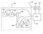
- FIG. 1 An embodiment of the invention is shown in the figure which shows an embodiment of a drive train of an agricultural harvester.
- a drive train 100 of an agricultural harvester includes an engine 102 that is coupled to and drives a series of first mechanical drive elements 104, here illustrated in simplified form as a gear train 104, although it may be any combination of shafts, gears, belts, pulleys, or other mechanical drive elements.
- Mechanical drive elements 104 are coupled to a power transmitting arrangement 105.
- Power transmitting arrangement 105 includes a first pulley 106 which, in turn, is coupled to and drives a second pulley 108.
- Belt 110 couples the pulleys 106 and 108 together to transmit power therebetween. Pulley 106, pulley 108 and belt 110 form power transmitting arrangement 105 in the form of a pulley and belt arrangement 111.
- Pulley 108 is coupled to and drives a load 112, which may be, for example, the rotor of an agricultural harvester, or a cleaning fan.
- load 112 which may be, for example, the rotor of an agricultural harvester, or a cleaning fan.
- all the mechanical elements in the drive train 100 rotate at speeds that are in fixed proportion to each other, unless, for example, the diameter of one of the pulleys is changed, or a gear ratio of a gearbox in drive train 100 is changed.
- a first speed sensor 114 is coupled to one of the first mechanical drive elements 104 in the drive train 100 that is on the engine side of pulley and belt arrangement 111.
- first speed sensor 114 is shown connected to engine 102.
- first speed sensor 114 is connected to any of the first mechanical drive elements 104 between engine 102 and pulley 106. Wherever first speed sensor 114 is located, it provides a speed signal 115 proportional to the speed of one of the first mechanical drive elements 104 on the drive (i.e. the engine) side of pulley and belt arrangement 111.
- a second speed sensor 116 is coupled to one of second mechanical drive elements 117 in the drive train 100 that is on the load side of pulley and belt arrangement 111.
- speed sensor 116 is coupled directly to load 112.
- it could be connected to second pulley 108 or to any of the second mechanical drive elements 117 coupling second pulley 108 to load 112.
- second speed sensor 116 it provides a speed signal 119 proportional to the speed of one of the second mechanical drive elements 117 on the load (i.e. the cleaning fan or threshing rotor) side of the pulley and belt arrangement 111.
- Pulley 106 and/or 108 is a variable diameter pulley.
- variable diameter we mean that the diameter of belt 110 as it travels over the pulley can be adjusted, typically by moving one side of the pulley closer to or further apart from the other side of the pulley, to close or, alternatively, to open the gap therebetween.
- the inner face of the sides of the pulley taper away from each other in the direction of the outer diameter of the pulley, so that belt 110 contacts the inner faces closer to the outside diameter when the sides that are closer together. As the belt moves closer to the outside diameter of the second pulley 108, the shaft supporting belt 110 rotates more slowly.
- This adjustment can be affected by a mechanical device, such as a mechanical linkage that forces the pulley sides together, or it may be hydraulic, such as by a piston that is moved by hydraulic fluid under pressure to force the pulley sides together.
- a mechanical device such as a mechanical linkage that forces the pulley sides together
- hydraulic such as by a piston that is moved by hydraulic fluid under pressure to force the pulley sides together.
- second pulley 108 is a variable diameter pulley, and is coupled to actuator 118 that is configured to change the diameter of second pulley 108 when so commanded by a control system 120.
- Control system 120 is coupled to drive train 100 to vary the speed of agricultural harvester load 112 relative to agricultural harvester engine 102.
- Control system 120 includes an electronic control unit (ECU) 122, an operator input device 124 (here shown as a keyboard), and an operator signaling device 126 (here illustrated as a visual display). Input device 124 and signaling device 126 are communicatively coupled to ECU 122.
- ECU electronice control unit
- operator input device 124 here shown as a keyboard
- operator signaling device 126 here illustrated as a visual display
- ECU 122 includes a digital microprocessor having random access memory (RAM), read only memory (ROM), and signal conditioning circuits that permit ECU 122 to drive operator signaling device 126 and to receive and process signals 123 from operator input device 124, to receive and process signals from speed sensors 114 and 116, and to transmit signals sufficient to drive actuator 118.
- ECU 122 is configured to indicate a speed of load 112 with signaling device 126, preferably by displaying the speed as numeric values on visual display device 126.
- ECU 122 is configured to receive speed command signals that the operator enters using operator input device 124.
- ECU 122 is also coupled to speed sensors 114 and 116 to receive signals therefrom that indicate the speed of one of the mechanical drive element 104 on the drive side of the pulley and belt arrangement 111 (in this case the engine) and to receive signals that indicate the speed of one of the second mechanical drive elements 117 on the load side of pulley and belt arrangement 111 (in this case, agricultural harvester load 112).
- ECU 122 is also coupled to actuator 118 to drive actuator 118 and, thereby, to change the diameter of second pulley 108.
- actuator 118 is configured to vary the diameter of second pulley 108.
- first pulley 106 is a variable diameter pulley and actuator 118 is coupled to pulley first 106 to vary the diameter of first pulley 106.
- ECU 122 continuously monitors the speed of load 112, reading second speed sensor 116 and displaying it on signaling device 126. Whenever the operator wishes to change the speed of load 112, he manipulates operator input device 124 to select a desired new speed for load 112, and this desired new speed is transmitted to ECU 122.
- ECU 122 On receipt of this speed, ECU 122 transmits the desired load speed to operator signaling device 126. ECU 122 also reads the actual engine speed indicated by speed sensor 114 at the same time and calculates a new speed ratio. The speed ratio being the desired new load speed divided by the actual engine speed at the moment the operator selected the desired new load speed and therefore before the engine speed has a chance to change significantly.
- ECU 122 sends a signal to actuator 118 to change the diameter of second pulley 108.
- load 112 on the engine 102 may change, either due to decreasing or increasing the load on engine 102 because the diameter of second pulley 108 is changing, or because of external conditions, such as changing ground terrain or density of the crop.
- ECU 122 When ECU 122 changes the diameter of second pulley 108, it also reads speed signals from first speed sensor 114 and second speed sensor 116 and calculates a ratio of the two. This instantaneous speed ratio changes as the diameter of second pulley 108 changes, the ratio gradually approaching the new speed ratio established at the outset of the speed change process.
- the diameter of second pulley 108 is typically not changed randomly, but is gradually moved stepwise from a smaller to a larger diameter, or a larger to a smaller diameter, depending on which change will cause the actual speed ratio to approach the new speed ratio.
- ECU 122 is configured to reverse the direction of change of the diameter of the variable pulley in order to make the actual speed ratio again approach the new speed ratio.
- ECU 122 is configured to keep sequentially repeating these steps of changing the diameter of second pulley 108 and reading the speed signals from speed sensors 114 and 116 until eventually the instantaneous speed ratio equals the new speed ratio (or alternatively comes within a predetermined value from the new speed ratio). When this happens, ECU 122 is configured to stop changing the diameter of second pulley 108 and exit its speed control loop until the operator enters another desired new load speed, at which time the entire process is repeated.
- control system 120 By controlling the diameter of the variable pulley based upon the ratio of engine speed to rotor speed instead of controlling the diameter of the variable pulley based upon the rotor speed alone, control system 120 becomes immune to any drift or change in engine speed as ECU 122 changes the diameter of second pulley 108.
- control system 120 is rendered immune to transient changes in engine speed, and the operator achieves what he desires: the load rotating at the desired speed when engine 102 is running at its initial speed.
Landscapes
- Engineering & Computer Science (AREA)
- General Engineering & Computer Science (AREA)
- Life Sciences & Earth Sciences (AREA)
- Environmental Sciences (AREA)
- Mechanical Engineering (AREA)
- Control Of Transmission Device (AREA)
- Transmissions By Endless Flexible Members (AREA)
Applications Claiming Priority (1)
| Application Number | Priority Date | Filing Date | Title |
|---|---|---|---|
| US99120007P | 2007-11-29 | 2007-11-29 |
Publications (1)
| Publication Number | Publication Date |
|---|---|
| EP2064934A2 true EP2064934A2 (de) | 2009-06-03 |
Family
ID=40385508
Family Applications (1)
| Application Number | Title | Priority Date | Filing Date |
|---|---|---|---|
| EP08165275A Withdrawn EP2064934A2 (de) | 2007-11-29 | 2008-09-26 | Landwirtschaftliche Erntemaschinen-Geschwindigkeitssteuerung |
Country Status (2)
| Country | Link |
|---|---|
| US (1) | US7748202B2 (de) |
| EP (1) | EP2064934A2 (de) |
Families Citing this family (4)
| Publication number | Priority date | Publication date | Assignee | Title |
|---|---|---|---|---|
| WO2015116892A1 (en) | 2014-01-31 | 2015-08-06 | Agco Corporation | Automatic load control for self-propelled windrower |
| US10624262B2 (en) * | 2018-03-29 | 2020-04-21 | Honda Motor Co., Ltd. | Closed-loop electronic slipping belt transmission speed control system for a walk-behind lawn mower |
| DE102019206829A1 (de) * | 2019-05-10 | 2020-11-12 | Deere & Company | Antriebssystem für eine Erntemaschine |
| JP7660406B2 (ja) * | 2021-03-18 | 2025-04-11 | 本田技研工業株式会社 | 作業機 |
Family Cites Families (6)
| Publication number | Priority date | Publication date | Assignee | Title |
|---|---|---|---|---|
| US4727710A (en) * | 1986-05-30 | 1988-03-01 | Deutz-Allis Corporation | Automatic vehicle ground speed control convertible to manual operation |
| DE19740346A1 (de) * | 1997-09-13 | 1999-03-18 | Claas Selbstfahr Erntemasch | Selbstfahrende Arbeitsmaschine |
| US6036597A (en) * | 1998-02-11 | 2000-03-14 | Agco Corporation | Combine harvester rotor load control |
| US7213389B2 (en) * | 2004-03-02 | 2007-05-08 | Deere & Company | Infinitely variable transmission for a combine header unit |
| US7261632B2 (en) * | 2004-06-21 | 2007-08-28 | Deere & Company | Self-propelled harvesting machine |
| US7549287B2 (en) * | 2007-09-14 | 2009-06-23 | Cnh America Llc | Hydrostatic auto/manual speed control |
-
2008
- 2008-09-04 US US12/204,242 patent/US7748202B2/en active Active
- 2008-09-26 EP EP08165275A patent/EP2064934A2/de not_active Withdrawn
Also Published As
| Publication number | Publication date |
|---|---|
| US20090139194A1 (en) | 2009-06-04 |
| US7748202B2 (en) | 2010-07-06 |
Similar Documents
| Publication | Publication Date | Title |
|---|---|---|
| US4893241A (en) | Crop processing apparatus | |
| CN101164401B (zh) | 棉花收获机行单元速度的同步控制 | |
| US20060191359A1 (en) | Agricultural machine with PTO torque limiting feature | |
| EP2068043B1 (de) | Arbeitsmaschine und Verfahren | |
| EP1595734B1 (de) | Kontrollsystem, insbesondere für einen Traktor | |
| US7632179B2 (en) | System and method for detecting combine rotor slugging | |
| US6213870B1 (en) | Stall prevention system | |
| US6984171B2 (en) | Hydro-mechanical threshing rotor control system for an agricultural combine | |
| DE10016435B4 (de) | Lüftungseinrichtung für ein landwirtschaftliches Fahrzeug | |
| EP3715167B1 (de) | Modul zur steuerung der motordrehzahl von aufsitzrasenausrüstungen | |
| US7172046B2 (en) | Four-wheel drive combine with slip control | |
| US7748202B2 (en) | Agricultural harvester speed control | |
| EP1371279A1 (de) | Mähdrescher mit einer Schätzvorrichtung um den hydraulischen Anordnungssdruck zu kontrollieren | |
| CN103797230B (zh) | 在可连续变化传动装置(cvt)中校正车辆速度滞后的系统和方法及相关车辆 | |
| US20090145682A1 (en) | Propulsion drive system for a utility vehicle | |
| US11612102B2 (en) | Drive system for a harvester | |
| EP2169276B1 (de) | Steuerung für ein stufenloses Getriebe | |
| US6937930B2 (en) | Transmission control system | |
| US7186201B2 (en) | Active combine rotor deceleration | |
| US7427231B2 (en) | Motor overspeed detection | |
| EP4420507A1 (de) | Feldhäcksler | |
| JPH02130232A (ja) | 農作業車の負荷制御装置 | |
| JPH04278843A (ja) | 作業車の制御装置 |
Legal Events
| Date | Code | Title | Description |
|---|---|---|---|
| PUAI | Public reference made under article 153(3) epc to a published international application that has entered the european phase |
Free format text: ORIGINAL CODE: 0009012 |
|
| AK | Designated contracting states |
Kind code of ref document: A2 Designated state(s): AT BE BG CH CY CZ DE DK EE ES FI FR GB GR HR HU IE IS IT LI LT LU LV MC MT NL NO PL PT RO SE SI SK TR |
|
| AX | Request for extension of the european patent |
Extension state: AL BA MK RS |
|
| STAA | Information on the status of an ep patent application or granted ep patent |
Free format text: STATUS: THE APPLICATION HAS BEEN WITHDRAWN |
|
| 18W | Application withdrawn |
Effective date: 20150404 |