EP2068043B1 - Arbeitsmaschine und Verfahren - Google Patents
Arbeitsmaschine und Verfahren Download PDFInfo
- Publication number
- EP2068043B1 EP2068043B1 EP08169927.4A EP08169927A EP2068043B1 EP 2068043 B1 EP2068043 B1 EP 2068043B1 EP 08169927 A EP08169927 A EP 08169927A EP 2068043 B1 EP2068043 B1 EP 2068043B1
- Authority
- EP
- European Patent Office
- Prior art keywords
- ivt
- engine
- output
- work machine
- brake
- Prior art date
- Legal status (The legal status is an assumption and is not a legal conclusion. Google has not performed a legal analysis and makes no representation as to the accuracy of the status listed.)
- Active
Links
- 238000000034 method Methods 0.000 title claims description 10
- 230000005540 biological transmission Effects 0.000 claims description 16
- 230000001419 dependent effect Effects 0.000 claims description 8
- 238000012545 processing Methods 0.000 claims description 5
- 238000012546 transfer Methods 0.000 claims description 5
- 238000002485 combustion reaction Methods 0.000 claims description 4
- 230000000994 depressogenic effect Effects 0.000 description 7
- 230000002706 hydrostatic effect Effects 0.000 description 5
- ATUOYWHBWRKTHZ-UHFFFAOYSA-N Propane Chemical compound CCC ATUOYWHBWRKTHZ-UHFFFAOYSA-N 0.000 description 2
- 238000010276 construction Methods 0.000 description 2
- 230000003247 decreasing effect Effects 0.000 description 2
- 238000013461 design Methods 0.000 description 2
- 239000000446 fuel Substances 0.000 description 2
- 230000007935 neutral effect Effects 0.000 description 2
- 235000010469 Glycine max Nutrition 0.000 description 1
- 244000068988 Glycine max Species 0.000 description 1
- 238000004378 air conditioning Methods 0.000 description 1
- 238000013459 approach Methods 0.000 description 1
- 230000006835 compression Effects 0.000 description 1
- 238000007906 compression Methods 0.000 description 1
- 239000002826 coolant Substances 0.000 description 1
- 238000001816 cooling Methods 0.000 description 1
- 238000003306 harvesting Methods 0.000 description 1
- 230000020169 heat generation Effects 0.000 description 1
- 238000002347 injection Methods 0.000 description 1
- 239000007924 injection Substances 0.000 description 1
- 238000005065 mining Methods 0.000 description 1
- 238000012986 modification Methods 0.000 description 1
- 230000004048 modification Effects 0.000 description 1
- 239000001294 propane Substances 0.000 description 1
- 239000000243 solution Substances 0.000 description 1
Images

Classifications
-
- F—MECHANICAL ENGINEERING; LIGHTING; HEATING; WEAPONS; BLASTING
- F16—ENGINEERING ELEMENTS AND UNITS; GENERAL MEASURES FOR PRODUCING AND MAINTAINING EFFECTIVE FUNCTIONING OF MACHINES OR INSTALLATIONS; THERMAL INSULATION IN GENERAL
- F16H—GEARING
- F16H61/00—Control functions within control units of change-speed- or reversing-gearings for conveying rotary motion ; Control of exclusively fluid gearing, friction gearing, gearings with endless flexible members or other particular types of gearing
- F16H61/21—Providing engine brake control
-
- F—MECHANICAL ENGINEERING; LIGHTING; HEATING; WEAPONS; BLASTING
- F16—ENGINEERING ELEMENTS AND UNITS; GENERAL MEASURES FOR PRODUCING AND MAINTAINING EFFECTIVE FUNCTIONING OF MACHINES OR INSTALLATIONS; THERMAL INSULATION IN GENERAL
- F16H—GEARING
- F16H15/00—Gearings for conveying rotary motion with variable gear ratio, or for reversing rotary motion, by friction between rotary members
- F16H15/02—Gearings for conveying rotary motion with variable gear ratio, or for reversing rotary motion, by friction between rotary members without members having orbital motion
- F16H15/04—Gearings providing a continuous range of gear ratios
-
- B—PERFORMING OPERATIONS; TRANSPORTING
- B60—VEHICLES IN GENERAL
- B60K—ARRANGEMENT OR MOUNTING OF PROPULSION UNITS OR OF TRANSMISSIONS IN VEHICLES; ARRANGEMENT OR MOUNTING OF PLURAL DIVERSE PRIME-MOVERS IN VEHICLES; AUXILIARY DRIVES FOR VEHICLES; INSTRUMENTATION OR DASHBOARDS FOR VEHICLES; ARRANGEMENTS IN CONNECTION WITH COOLING, AIR INTAKE, GAS EXHAUST OR FUEL SUPPLY OF PROPULSION UNITS IN VEHICLES
- B60K17/00—Arrangement or mounting of transmissions in vehicles
- B60K17/04—Arrangement or mounting of transmissions in vehicles characterised by arrangement, location, or kind of gearing
- B60K17/06—Arrangement or mounting of transmissions in vehicles characterised by arrangement, location, or kind of gearing of change-speed gearing
-
- B—PERFORMING OPERATIONS; TRANSPORTING
- B60—VEHICLES IN GENERAL
- B60W—CONJOINT CONTROL OF VEHICLE SUB-UNITS OF DIFFERENT TYPE OR DIFFERENT FUNCTION; CONTROL SYSTEMS SPECIALLY ADAPTED FOR HYBRID VEHICLES; ROAD VEHICLE DRIVE CONTROL SYSTEMS FOR PURPOSES NOT RELATED TO THE CONTROL OF A PARTICULAR SUB-UNIT
- B60W10/00—Conjoint control of vehicle sub-units of different type or different function
- B60W10/04—Conjoint control of vehicle sub-units of different type or different function including control of propulsion units
- B60W10/06—Conjoint control of vehicle sub-units of different type or different function including control of propulsion units including control of combustion engines
-
- B—PERFORMING OPERATIONS; TRANSPORTING
- B60—VEHICLES IN GENERAL
- B60W—CONJOINT CONTROL OF VEHICLE SUB-UNITS OF DIFFERENT TYPE OR DIFFERENT FUNCTION; CONTROL SYSTEMS SPECIALLY ADAPTED FOR HYBRID VEHICLES; ROAD VEHICLE DRIVE CONTROL SYSTEMS FOR PURPOSES NOT RELATED TO THE CONTROL OF A PARTICULAR SUB-UNIT
- B60W10/00—Conjoint control of vehicle sub-units of different type or different function
- B60W10/10—Conjoint control of vehicle sub-units of different type or different function including control of change-speed gearings
- B60W10/101—Infinitely variable gearings
-
- B—PERFORMING OPERATIONS; TRANSPORTING
- B60—VEHICLES IN GENERAL
- B60W—CONJOINT CONTROL OF VEHICLE SUB-UNITS OF DIFFERENT TYPE OR DIFFERENT FUNCTION; CONTROL SYSTEMS SPECIALLY ADAPTED FOR HYBRID VEHICLES; ROAD VEHICLE DRIVE CONTROL SYSTEMS FOR PURPOSES NOT RELATED TO THE CONTROL OF A PARTICULAR SUB-UNIT
- B60W10/00—Conjoint control of vehicle sub-units of different type or different function
- B60W10/18—Conjoint control of vehicle sub-units of different type or different function including control of braking systems
- B60W10/184—Conjoint control of vehicle sub-units of different type or different function including control of braking systems with wheel brakes
-
- B—PERFORMING OPERATIONS; TRANSPORTING
- B60—VEHICLES IN GENERAL
- B60W—CONJOINT CONTROL OF VEHICLE SUB-UNITS OF DIFFERENT TYPE OR DIFFERENT FUNCTION; CONTROL SYSTEMS SPECIALLY ADAPTED FOR HYBRID VEHICLES; ROAD VEHICLE DRIVE CONTROL SYSTEMS FOR PURPOSES NOT RELATED TO THE CONTROL OF A PARTICULAR SUB-UNIT
- B60W30/00—Purposes of road vehicle drive control systems not related to the control of a particular sub-unit, e.g. of systems using conjoint control of vehicle sub-units, or advanced driver assistance systems for ensuring comfort, stability and safety or drive control systems for propelling or retarding the vehicle
- B60W30/18—Propelling the vehicle
- B60W30/18009—Propelling the vehicle related to particular drive situations
- B60W30/18072—Coasting
-
- B—PERFORMING OPERATIONS; TRANSPORTING
- B60—VEHICLES IN GENERAL
- B60W—CONJOINT CONTROL OF VEHICLE SUB-UNITS OF DIFFERENT TYPE OR DIFFERENT FUNCTION; CONTROL SYSTEMS SPECIALLY ADAPTED FOR HYBRID VEHICLES; ROAD VEHICLE DRIVE CONTROL SYSTEMS FOR PURPOSES NOT RELATED TO THE CONTROL OF A PARTICULAR SUB-UNIT
- B60W30/00—Purposes of road vehicle drive control systems not related to the control of a particular sub-unit, e.g. of systems using conjoint control of vehicle sub-units, or advanced driver assistance systems for ensuring comfort, stability and safety or drive control systems for propelling or retarding the vehicle
- B60W30/18—Propelling the vehicle
- B60W30/18009—Propelling the vehicle related to particular drive situations
- B60W30/18109—Braking
- B60W30/18136—Engine braking
-
- F—MECHANICAL ENGINEERING; LIGHTING; HEATING; WEAPONS; BLASTING
- F16—ENGINEERING ELEMENTS AND UNITS; GENERAL MEASURES FOR PRODUCING AND MAINTAINING EFFECTIVE FUNCTIONING OF MACHINES OR INSTALLATIONS; THERMAL INSULATION IN GENERAL
- F16H—GEARING
- F16H61/00—Control functions within control units of change-speed- or reversing-gearings for conveying rotary motion ; Control of exclusively fluid gearing, friction gearing, gearings with endless flexible members or other particular types of gearing
- F16H61/38—Control of exclusively fluid gearing
- F16H61/40—Control of exclusively fluid gearing hydrostatic
- F16H61/46—Automatic regulation in accordance with output requirements
- F16H61/468—Automatic regulation in accordance with output requirements for achieving a target input torque
-
- B—PERFORMING OPERATIONS; TRANSPORTING
- B60—VEHICLES IN GENERAL
- B60W—CONJOINT CONTROL OF VEHICLE SUB-UNITS OF DIFFERENT TYPE OR DIFFERENT FUNCTION; CONTROL SYSTEMS SPECIALLY ADAPTED FOR HYBRID VEHICLES; ROAD VEHICLE DRIVE CONTROL SYSTEMS FOR PURPOSES NOT RELATED TO THE CONTROL OF A PARTICULAR SUB-UNIT
- B60W2720/00—Output or target parameters relating to overall vehicle dynamics
- B60W2720/10—Longitudinal speed
-
- F—MECHANICAL ENGINEERING; LIGHTING; HEATING; WEAPONS; BLASTING
- F16—ENGINEERING ELEMENTS AND UNITS; GENERAL MEASURES FOR PRODUCING AND MAINTAINING EFFECTIVE FUNCTIONING OF MACHINES OR INSTALLATIONS; THERMAL INSULATION IN GENERAL
- F16H—GEARING
- F16H61/00—Control functions within control units of change-speed- or reversing-gearings for conveying rotary motion ; Control of exclusively fluid gearing, friction gearing, gearings with endless flexible members or other particular types of gearing
- F16H61/02—Control functions within control units of change-speed- or reversing-gearings for conveying rotary motion ; Control of exclusively fluid gearing, friction gearing, gearings with endless flexible members or other particular types of gearing characterised by the signals used
- F16H61/0202—Control functions within control units of change-speed- or reversing-gearings for conveying rotary motion ; Control of exclusively fluid gearing, friction gearing, gearings with endless flexible members or other particular types of gearing characterised by the signals used the signals being electric
- F16H61/0204—Control functions within control units of change-speed- or reversing-gearings for conveying rotary motion ; Control of exclusively fluid gearing, friction gearing, gearings with endless flexible members or other particular types of gearing characterised by the signals used the signals being electric for gearshift control, e.g. control functions for performing shifting or generation of shift signal
- F16H61/0213—Control functions within control units of change-speed- or reversing-gearings for conveying rotary motion ; Control of exclusively fluid gearing, friction gearing, gearings with endless flexible members or other particular types of gearing characterised by the signals used the signals being electric for gearshift control, e.g. control functions for performing shifting or generation of shift signal characterised by the method for generating shift signals
- F16H2061/0234—Adapting the ratios to special vehicle conditions
- F16H2061/0237—Selecting ratios for providing engine braking
-
- Y—GENERAL TAGGING OF NEW TECHNOLOGICAL DEVELOPMENTS; GENERAL TAGGING OF CROSS-SECTIONAL TECHNOLOGIES SPANNING OVER SEVERAL SECTIONS OF THE IPC; TECHNICAL SUBJECTS COVERED BY FORMER USPC CROSS-REFERENCE ART COLLECTIONS [XRACs] AND DIGESTS
- Y02—TECHNOLOGIES OR APPLICATIONS FOR MITIGATION OR ADAPTATION AGAINST CLIMATE CHANGE
- Y02T—CLIMATE CHANGE MITIGATION TECHNOLOGIES RELATED TO TRANSPORTATION
- Y02T10/00—Road transport of goods or passengers
- Y02T10/60—Other road transportation technologies with climate change mitigation effect
-
- Y—GENERAL TAGGING OF NEW TECHNOLOGICAL DEVELOPMENTS; GENERAL TAGGING OF CROSS-SECTIONAL TECHNOLOGIES SPANNING OVER SEVERAL SECTIONS OF THE IPC; TECHNICAL SUBJECTS COVERED BY FORMER USPC CROSS-REFERENCE ART COLLECTIONS [XRACs] AND DIGESTS
- Y10—TECHNICAL SUBJECTS COVERED BY FORMER USPC
- Y10S—TECHNICAL SUBJECTS COVERED BY FORMER USPC CROSS-REFERENCE ART COLLECTIONS [XRACs] AND DIGESTS
- Y10S477/00—Interrelated power delivery controls, including engine control
- Y10S477/904—Control signal is acceleration
- Y10S477/905—Acceleration of throttle signal
Definitions
- the present invention relates to a work machine according to the preamble of claim 1, and to a method according to the preamble of claim 6.
- GB 2 316 142 A discloses an electronically controlled, continuously variable transmission (CVT), wherein during braking operation the adjustment of the transmission ratio being such that a constant engine braking moment is applied.
- CVT continuously variable transmission
- A1 discloses a hydrostatic vehicle drive system having a braking system designed to emulate the braking response of a mechanically driven vehicle equipped with an automatic transmission and disk or drum brakes.
- a work machine such as a construction work machine, an agricultural work machine or a forestry work machine, typically includes a prime mover in the form of an internal combustion (IC) engine.
- the IC engine may either be in the form of a compression ignition engine (i.e., diesel engine) or a spark ignition engine (i.e., gasoline engine).
- the prime mover is in the form of a diesel engine having better lugging, pull-down and torque characteristics for associated work operations.
- An IC engine may be coupled with an IVT which provides continuous variable output speed from 0 to maximum in a stepless fashion.
- An IVT typically includes hydrostatic and mechanical gearing components. The hydrostatic components convert rotating shaft power to hydraulic flow and vice versa. The power flow through an IVT can be through the hydrostatic components only, through the mechanical components only, or through a combination of both depending on the design and output speed.
- an IVT for use in a work machine is a hydromechanical transmission which includes a hydraulic module coupled with a planetary gear set.
- a hydrostatic transmission which includes a hydraulic module coupled with a gear set.
- the deceleration rate with an IVT can be more abrupt than a traditional torque converter powershift transmission when the ground speed control pedal is fully released.
- the IVT ratio of input to output speed increases as the speed control pedal is released and the vehicle inertia back drives the engine and abruptly slows down the vehicle. This brings the vehicle to a stop quickly and is undesirable to the operator.
- the work machine may further comprise an internal combustion (IC) engine having an output; an infinitely variable transmission (IVT) having an input coupled with said IC engine output; a brake actuator; a brake sensor associated with said brake actuator, said brake sensor providing a first output signal indicating an actuation of said brake actuator; and at least one electrical processing circuit configured for increasing an input/output (I/O) ratio of said IVT, dependent upon said first output signal, such that said IVT input back-drives said IC engine output.
- IC internal combustion
- IVTT infinitely variable transmission
- the work machine may further include at least one service brake, wherein said brake sensor provides a second output signal indicating a further actuation of said brake actuator, said at least one electrical processing circuit configured for actuating said service brake, dependent upon said second output signal.
- Said brake actuator may comprise a brake pedal.
- Fig. 1 there is shown a schematic illustration of an embodiment of a work machine 10 of the present invention.
- Work machine 10 is assumed to be a construction work machine such as a John Deere front end loader, but could be a different type of work machine such as an agricultural, forestry, mining or industrial work machine.
- Work machine 10 includes an IC engine 12 which is coupled with an IVT 14, typically directly to the flywheel and flywheel housing of IC engine 12, or remotely via a drive shaft that connects the IC engine output to the IVT input.
- IC engine 12 is assumed to be a diesel engine in the illustrated embodiment, but could also be a gasoline engine, propane engine, etc.
- IC engine 12 is sized and configured according to the application.
- IVT 14 may be of conventional design, and thus is not described in great detail herein. IVT 14 has an output which is coupled with at least one other downstream drive train component 18, which in turn is coupled with a plurality of drive wheels 20, one of which is shown in Fig. 1 . Of course, it will be appreciated that in the case of a track-type work vehicle, drive train component 18 may be coupled with a ground engaging track.
- IVT 14 also provides output power to one or more external loads 22, which in turn thus provide an additional load on IC engine 12.
- External loads 22 typically are in the form of hydraulic loads, such as a front end loader boom, bucket, and steering functions, backhoe hydraulic functions, grain unloading auger function, tree felling saw motor, etc.
- IC engine 12 also provides power directly to auxiliary loads 23 such as a cooling fan or fans, air conditioning compressor, alternator, air compressor, or hydraulic pumps that provide power to non-implement functions.
- the total load placed upon IC engine 12 thus is a function of tractive loads, external hydraulic loads and auxiliary loads.
- Engine control unit (ECU) 24 electronically controls operation of IC engine 12, and is coupled with a plurality of sensors and actuators (not specifically shown) associated with operation of IC engine 12.
- ECU 24 may be coupled with sensors indicating engine control parameters such as an air flow rate within one or more intake manifolds, engine speed, crankshaft position, fueling rate and/or timing, exhaust gas recirculation (EGR) rate, coolant temperature, oil pressure, turbocharger blade position, etc.
- ECU 24 may receive output signals from vehicle control unit (VCU) 28 representing vehicle control parameters input by an operator, such as, e.g., a commanded ground speed using a ground speed actuator or a speed range using a speed range select lever.
- ECU 24 calculates threoretical gross engine power and distributes this value to controller area network (CAN) bus 30.
- ECU 24 may be coupled with actuators that control fuel quantity, fuel injection timing, EGR valve position, etc.
- transmission control unit (TCU) 26 electronically controls operation of IVT 14, and is coupled with a plurality of sensors associated with operation of IVT 14.
- ECU 24 and TCU 26 are coupled together via a bus structure providing two-way data flow, such as CAN bus 30.
- VCU 28 may receive signals from external loads 22 and auxiliary loads 23 that represent significant loads. Such signals can represent actual loads or allow calculation of external and auxiliary loads. Load values may be distributed to CAN bus 30.
- ECU 24, TCU 26 and VCU 28 are shown coupled together using wired connections, it should also be understood that wireless connections may be used for certain applications.
- Ground speed actuator 32 is moved by an operator to a position corresponding to a desired ground speed of work machine 10.
- ground speed actuator 32 is assumed to be a foot pedal which is biased to a neutral position, and depressed and held by an operator at a position corresponding to a desired ground speed. It is to be understood, however, that ground speed actuator 32 could be differently configured, such as a rocker type foot pedal including both forward and reverse functions, or a hand lever.
- ground speed actuator 32 is assumed to be a movable mechanical element in the form of a foot pedal.
- the position of the foot pedal is electronically sensed using desired speed sensor 34 and transmitted to TCU 26.
- the output signal representing the position of the foot pedal can be directly interpreted to a corresponding desired ground speed of work machine 10.
- ground speed actuator 32 could be an actual mechanical linkage which is mechanically connected to IVT 14 and/or other drive train component 18.
- desired speed sensor 34 could transmit a signal directly to VCU 28 representing the position of ground speed actuator 32, and in turn the desired ground speed of work machine 10.
- Brake actuator 36 is moved by an operator to a position corresponding to a desired degree of braking of work machine 10.
- brake actuator 36 is assumed to be a foot pedal which is biased to a neutral position, and depressed and held by an operator at a position corresponding to a desired deceleration rate.
- the position of the foot pedal is electronically sensed using brake sensor 38 and transmitted to TCU 26 (or alternatively VCU 28).
- the output signal representing the position of the foot pedal can be directly interpreted to a corresponding application pressure of service brakes 40.
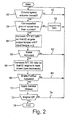
- a query is made as to whether the ground speed actuator 32 (e.g., foot pedal) has been moved. If the ground speed actuator 32 has not been moved (line 52), then a wait state occurs. On the other hand, if the ground speed actuator 32 has been moved (decision block 54), then a determination is made as to whether the desired ground speed is to be increased or decreased. In the event the ground speed is to be increased (block 56), the I/O ratio of IVT 14 is simply adjusted accordingly.
- the ground speed actuator 32 e.g., foot pedal
- the I/O ratio of IVT 14 is increased until the net torque transfer back-driven from the input of IVT 14 to the output of IC engine 12 is approximately zero.
- TCU 26 monitors the output torque from IC engine 12 via ECU 24, and external and auxiliary loads via VCU 28. External and auxiliary load requirements are deducted from the gross output torque of IC engine 12 to determine the net torque to IVT 14.
- TCU 26 adjusts the I/O ratio of IVT 14 accordingly to maintain net torque transfer from IC engine 12 to IVT 14 of substantially zero. This allows work machine 10 to coast without abrupt slowing which may be more desirable to the operator.
- the I/O ratio of IVT 14 is adjusted to allow positive torque transfer from IC engine 12 to IVT 14 to maintain ground speed.
- a query is made as to whether the brake actuator 36 (e.g., brake pedal) has been depressed. If not, then control loops back to the input to decision block 50 (line 62). If the brake actuator 36 has been depressed, then the I/O ratio of IVT 14 is further increased such that IC engine 12 is back driven (engine operating speed (RPM) increases) resulting in engine braking of work machine 10 (block 64). Engine braking prevents heat generation in and prolongs the life of service brakes 40. The engine speed can be increased to a maximum predetermined engine speed as the brake pedal is further depressed to achieve additional engine braking.
- the brake actuator 36 e.g., brake pedal
- a query is made as to whether brake actuator 36 has been further depressed by an operator to a point past that of the maximum engine speed for engine braking. If not, then control loops back to the input to decision block 50 (line 68). If the brake actuator has been further depressed, then the service brakes are applied (block 70).
- control logic repeats while IC engine 12 is in an ON state (decision block 72 and line 74), and terminates when IC engine 12 is turned OFF (block 76).
Claims (10)
- Arbeitsmaschine (10), die Folgendes umfasst:eine Brennkraftmaschine (IC-Maschine)(12), die einen Ausgang hat;ein stufenlos verstellbares Getriebe (IVT)(14), das einen Eingang hat, der mit dem Ausgang der IC-Maschine gekoppelt ist;einen Reisegeschwindigkeitsaktor (32);einen Sollgeschwindigkeitssensor (34), der mit dem Reisegeschwindigkeitsaktor (32) verbunden ist und ein Ausgangssignal bereitstellt, das eine geringere Reisegeschwindigkeit anzeigt; undeine Getriebesteuereinheit (26), die elektronisch den IVT-Betrieb steuert und konfiguriert ist, in Abhängigkeit von dem Sensorausgangssignal ein Eingangs/Ausgangsverhältnis (E/A-Verhältnis) des IVT (14) zu erhöhen, derart, dass eine Nettodrehmomentübertragung, die von dem IVT-Eingang an den IC-Maschinenausgang zurückgeführt worden ist, im Wesentlichen Null ist, dadurch gekennzeichnet, dass die Getriebesteuereinheit (26) die Drehmomentausgabe von der IC-Maschine (12) über eine elektronische Steuereinheit (24) und äußere und zusätzliche Lasten über eine Fahrzeugsteuereinheit (28) überwacht, woraus äußere und zusätzliche Lastanforderungen von der Gesamtdrehmomentausgabe der IC-Maschine (12) hergeleitet werden, um die Nettodrehmomentübertragung der IVT (14) zu bestimmen.
- Arbeitsmaschine nach Anspruch 1, gekennzeichnet durch eine Bremsbetätigungsvorrichtung (36) und einen Bremssensor (38), der mit der Bremsbetätigungsvorrichtung (36) verbunden ist, wobei der Bremssensor (38) ein erstes Ausgangssignal bereitstellt, das eine Betätigung der Bremsbetätigungsvorrichtung (36) anzeigt, wobei die mindestens eine elektrische Verarbeitungsschaltung konfiguriert ist, in Abhängigkeit von dem ersten Ausgangssignal das E/A-Verhältnis des IVT (14) zu erhöhen, derart, dass der IVT-Eingang den IC-Maschinenausgang zurückführt, wobei die Bremsbetätigungsvorrichtung (36) vorzugsweise ein Bremspedal umfasst.
- Arbeitsmaschine nach Anspruch 2, gekennzeichnet durch mindestens eine Betriebsbremse (40), wobei der Bremssensor (38) ein zweites Ausgangssignal bereitstellt, das eine weitere Betätigung der Bremsbetätigungsvorrichtung (36) anzeigt, wobei die mindestens eine elektrische Verarbeitungsschaltung konfiguriert ist, in Abhängigkeit von dem zweiten Ausgangssignal die Betriebsbremse (40) zu betätigen.
- Arbeitsmaschine nach einem oder mehreren der vorhergehenden Ansprüche, dadurch gekennzeichnet, dass der Reisegeschwindigkeitsaktor (32) ein Fußpedal und/oder einen Handschalthebel umfasst.
- Arbeitsmaschine nach einem oder mehreren der vorhergehenden Ansprüche, dadurch gekennzeichnet, dass die mindestens eine elektrische Verarbeitungsschaltung eine Kraftmaschinensteuereinheit (ECU) (24), die mit der IC-Maschine (12) verbunden ist, und eine Getriebesteuereinheit (TCU) (26), die mit dem IVT (14) verbunden ist, enthält, wobei die TCU (26) das E/A-Verhältnis des IVT (14) steuert.
- Verfahren zum Betreiben einer Arbeitsmaschine (10), die eine Brennkraftmaschine (IC-Maschine)(12), die einen Ausgang, der mit einem Eingang zu einem stufenlos verstellbaren Getriebe (IVT)(14) gekoppelt ist, aufweist, und eine Getriebesteuereinheit (26), die den IVT-Betrieb elektronisch steuert und konfiguriert ist, ein Eingangs/Ausgangsverhältnis (E/A-Verhältnis) des IVT (14) zu erhöhen, enthält, wobei das Verfahren die folgenden Schritte umfasst: Bewegen eines Reisegeschwindigkeitsaktors (32) an eine Position, die einer geringeren Reisegeschwindigkeit der Arbeitsmaschine (10) entspricht; Erfassen der Position des Reisegeschwindigkeitsaktors (32) und Bereitstellen eines Ausgangssignals, das die geringere Reisegeschwindigkeit anzeigt; und in Abhängigkeit von dem erfassten Ausgangssignal Erhöhen eines Eingangs/Ausgangsverhältnisses (E/A-Verhältnisses) des IVT (14), derart, dass eine Nettodrehmomentübertragung, die von dem IVT-Eingang an den IC-Maschinenausgang zurückgeführt worden ist, im Wesentlichen Null ist, gekennzeichnet durch den folgenden Schritt: die Getriebesteuereinheit (26) überwacht die Drehmomentausgabe von der IC-Maschine (12) über eine elektronische Steuereinheit (24) und äußere und zusätzliche Lasten über eine Fahrzeugsteuereinheit (28), woraus äußere und zusätzliche Lastanforderungen von der Gesamtdrehmomentausgabe der IC-Maschine (12) hergeleitet werden, um die Nettodrehmomentübertragung des IVT (14) zu bestimmen.
- Verfahren zum Betreiben einer Arbeitsmaschine nach Anspruch 6, gekennzeichnet durch die folgenden Schritte: Betätigen einer Bremsbetätigungsvorrichtung (36); Erfassen der Betätigung der Bremsbetätigungsvorrichtung (36) und Bereitstellen eines ersten Ausgangssignals, das eine Betätigung der Bremsbetätigungsvorrichtung (36) anzeigt; und in Abhängigkeit von dem ersten Ausgangssignal Erhöhen des E/A-Verhältnisses des IVT (14), derart, dass die IVT-Eingangs den IC-Maschinenausgang zurückführt, wobei die Bremsbetätigungsvorrichtung (36) vorzugsweise ein Bremspedal umfasst.
- Verfahren zum Betreiben einer Arbeitsmaschine nach Anspruch 6 oder 7, gekennzeichnet durch die folgenden Schritte: Erfassen einer weiteren Betätigung der Bremsbetätigungsvorrichtung (36) und Bereitstellen eines zweiten Ausgangssignals, das die weitere Betätigung der Bremsbetätigungsvorrichtung (36) anzeigt; und in Abhängigkeit von dem zweiten Ausgangssignal Betätigen mindestens einer Betriebsbremse (40).
- Verfahren zum Betreiben einer Arbeitsmaschine nach einem oder mehreren der Ansprüche 6 bis 8, dadurch gekennzeichnet, dass der Reisegeschwindigkeitsaktor (32) ein Fußpedal und/oder einen Handschalthebel umfasst.
- Verfahren zum Betreiben einer Arbeitsmaschine nach einem oder mehreren der Ansprüche 6 bis 9, dadurch gekennzeichnet, dass der Schritt des Erhöhens des E/A-Verhältnisses unter Verwendung einer Kraftmaschinensteuereinheit (ECU) (24), die mit der IC-Maschine (12) verbunden ist, und einer Getriebesteuereinheit (TCU) (26), die mit dem IVT (14) verbunden ist, ausgeführt wird, wobei die TCU (26) das E/A-Verhältnis der IVT (14) steuert.
Applications Claiming Priority (1)
| Application Number | Priority Date | Filing Date | Title |
|---|---|---|---|
| US11/952,571 US8070651B2 (en) | 2007-12-07 | 2007-12-07 | Work machine coast and brake control with an infinitely variable transmission |
Publications (3)
| Publication Number | Publication Date |
|---|---|
| EP2068043A2 EP2068043A2 (de) | 2009-06-10 |
| EP2068043A3 EP2068043A3 (de) | 2011-07-20 |
| EP2068043B1 true EP2068043B1 (de) | 2013-07-31 |
Family
ID=40466898
Family Applications (1)
| Application Number | Title | Priority Date | Filing Date |
|---|---|---|---|
| EP08169927.4A Active EP2068043B1 (de) | 2007-12-07 | 2008-11-25 | Arbeitsmaschine und Verfahren |
Country Status (9)
| Country | Link |
|---|---|
| US (1) | US8070651B2 (de) |
| EP (1) | EP2068043B1 (de) |
| JP (1) | JP5536327B2 (de) |
| KR (1) | KR20090060192A (de) |
| CN (1) | CN101486344A (de) |
| BR (1) | BRPI0805252B1 (de) |
| CA (1) | CA2645775C (de) |
| MX (1) | MX2008015458A (de) |
| RU (1) | RU2542856C2 (de) |
Families Citing this family (16)
| Publication number | Priority date | Publication date | Assignee | Title |
|---|---|---|---|---|
| US8457848B2 (en) * | 2007-10-31 | 2013-06-04 | Deere & Company | Work machine with IVT output automatically adjusted dependent upon engine load |
| US8938343B2 (en) | 2011-06-23 | 2015-01-20 | Caterpillar Inc. | Automatic sequential accessory machine retarding on a grade |
| JP5982766B2 (ja) * | 2011-09-26 | 2016-08-31 | 日産自動車株式会社 | 自動変速機の変速制御装置 |
| US8494731B2 (en) | 2011-11-23 | 2013-07-23 | Caterpillar Inc. | Method of controlling gear ratio rate of change in continuously variable transmission |
| US8954245B2 (en) | 2012-01-13 | 2015-02-10 | Caterpillar Inc. | Method of controlling gear ratio rate of change in continuously variable transmission |
| US9002595B2 (en) | 2012-11-01 | 2015-04-07 | Caterpillar Inc. | Torque and speed control in a machine with continuously variable transmission |
| US8545368B1 (en) | 2012-11-01 | 2013-10-01 | Caterpillar Inc. | Regulation of a machine with a continuously variable transmission and service brakes |
| US8585543B1 (en) | 2012-11-01 | 2013-11-19 | Caterpillar Inc. | Speed control for a machine with a continuously variable transmission |
| US9169926B2 (en) | 2012-11-01 | 2015-10-27 | Caterpillar Inc. | System and method of operating a machine having a continuously variable transmission |
| US8795133B2 (en) | 2012-11-01 | 2014-08-05 | Caterpillar Inc. | Event-based retarding in a machine with a continuously variable transmission |
| US8849527B2 (en) | 2012-11-01 | 2014-09-30 | Caterpillar Inc. | Speed control for a machine with a continuously variable transmission |
| CN106061813A (zh) * | 2013-12-03 | 2016-10-26 | 克拉克设备公司 | 动力机械以及用于启动和制动所述动力机械的控制方法 |
| US9091343B1 (en) | 2014-01-14 | 2015-07-28 | Caterpillar Inc. | Infinitely variable transmission with controlled coasting |
| CA2937957C (en) * | 2014-01-31 | 2016-12-06 | Agco Corporation | Automatic load control for self-propelled windrower |
| US10053064B2 (en) | 2016-08-15 | 2018-08-21 | Caterpillar Inc. | System and method for controlling braking of autonomous machine |
| DE102019117758A1 (de) * | 2019-07-02 | 2021-01-07 | Schaeffler Technologies AG & Co. KG | Hybridgetriebe mit integriertem Klimakompressor für ein Kraftfahrzeug; sowie Kraftfahrzeug |
Family Cites Families (18)
| Publication number | Priority date | Publication date | Assignee | Title |
|---|---|---|---|---|
| DE2934269A1 (de) | 1979-08-24 | 1981-03-26 | Zahnradfabrik Friedrichshafen | Automatische regeleinrichtung eines durch eine brennkraftmaschine angetriebenen, stufenlos einstellbaren uebersetzungsgetriebes, insbesondere fuer fahrzeuge |
| US4635494A (en) | 1983-10-03 | 1987-01-13 | Conklin Emmett D | Infinitely variable transmission and control apparatus therefor |
| NL8403461A (nl) | 1984-11-13 | 1986-06-02 | Doornes Transmissie Bv | Traploos variabele overbrenging. |
| EP0313275B1 (de) * | 1987-10-19 | 1994-01-12 | Honda Giken Kogyo Kabushiki Kaisha | Verfahren zur Steuerung des Übersetzungsverhältnisses eines stufenlos veränderlichen Getriebes |
| US5267911A (en) | 1988-09-10 | 1993-12-07 | Michael Meyerle | Hydromechanically infinitely variable transmission, with power splitting, particularly for motor vehicles |
| DE3903877C1 (de) | 1989-02-10 | 1990-09-13 | Friedrich Prof. Dr.-Ing. 4300 Essen De Jarchow | |
| DE4120546C2 (de) | 1991-06-21 | 1995-04-13 | Porsche Ag | Einrichtung zur Steuerung eines stufenlosen Kraftfahrzeuggetriebes |
| GB2316142B (en) * | 1993-03-31 | 1998-04-01 | Bosch Gmbh Robert | Method for operating a motor vehicle having a continuously variable transmission |
| DE19506062A1 (de) | 1995-02-22 | 1996-09-05 | Deere & Co | Hydrostatisch-mechanisches Leistungsverzweigungsgetriebe |
| CA2231491A1 (en) * | 1998-04-16 | 1999-10-16 | Rene Chamberland | Reversible driven pulley |
| JP2001071771A (ja) | 1999-09-03 | 2001-03-21 | Honda Motor Co Ltd | 内燃機関のパワーユニット |
| WO2002048581A1 (en) * | 2000-12-11 | 2002-06-20 | Bombardier Inc. | Virtual braking system for hydrostatically driven vehicle |
| GB2400422B (en) * | 2000-12-23 | 2004-12-08 | Jeremy Bernard Cooper | Continuously variable transmission using spring and oscillating shaft |
| US6896088B2 (en) * | 2001-10-12 | 2005-05-24 | Clark Equipment Company | Operation of wheeled work machine |
| DE10319880A1 (de) | 2003-05-03 | 2004-11-18 | Daimlerchrysler Ag | Antriebsstrang mit einer Brennkraftmaschine und zwei elektrischen Antriebsaggregaten |
| US7296496B2 (en) * | 2005-01-12 | 2007-11-20 | Caterpillar Inc. | Method of slowing a hydrostatic drive work machine |
| US7247122B2 (en) * | 2005-01-12 | 2007-07-24 | Caterpillar Inc. | Downshift in hydrostatic drive work machine |
| JP2007032767A (ja) * | 2005-07-28 | 2007-02-08 | Nsk Ltd | 車両用無段変速機の変速比制御装置 |
-
2007
- 2007-12-07 US US11/952,571 patent/US8070651B2/en active Active
-
2008
- 2008-11-25 EP EP08169927.4A patent/EP2068043B1/de active Active
- 2008-11-27 RU RU2008146939/11A patent/RU2542856C2/ru active
- 2008-12-04 MX MX2008015458A patent/MX2008015458A/es active IP Right Grant
- 2008-12-04 JP JP2008309239A patent/JP5536327B2/ja not_active Expired - Fee Related
- 2008-12-04 CA CA2645775A patent/CA2645775C/en active Active
- 2008-12-05 CN CNA200810182408XA patent/CN101486344A/zh active Pending
- 2008-12-05 BR BRPI0805252-2A patent/BRPI0805252B1/pt active IP Right Grant
- 2008-12-05 KR KR1020080123033A patent/KR20090060192A/ko not_active Application Discontinuation
Also Published As
| Publication number | Publication date |
|---|---|
| CA2645775A1 (en) | 2009-06-07 |
| EP2068043A3 (de) | 2011-07-20 |
| RU2008146939A (ru) | 2010-06-10 |
| RU2542856C2 (ru) | 2015-02-27 |
| CA2645775C (en) | 2016-05-10 |
| BRPI0805252A2 (pt) | 2011-10-18 |
| BRPI0805252B1 (pt) | 2019-05-28 |
| CN101486344A (zh) | 2009-07-22 |
| JP5536327B2 (ja) | 2014-07-02 |
| JP2009138940A (ja) | 2009-06-25 |
| US20090149296A1 (en) | 2009-06-11 |
| EP2068043A2 (de) | 2009-06-10 |
| MX2008015458A (es) | 2009-07-03 |
| US8070651B2 (en) | 2011-12-06 |
| KR20090060192A (ko) | 2009-06-11 |
Similar Documents
| Publication | Publication Date | Title |
|---|---|---|
| EP2068043B1 (de) | Arbeitsmaschine und Verfahren | |
| EP2072365B1 (de) | Arbeitsmaschine mit Brennkraftmaschine und Stufenloses Getriebe mit Brennkraftmaschine | |
| EP2055544B1 (de) | Arbeitsmaschine und Verfahren | |
| EP2055543B1 (de) | Arbeitsmaschine und Verfahren | |
| CA2641232A1 (en) | Work machine with torque limiting control for an infinitely variable transmission | |
| US7022044B2 (en) | Drive train for powering a mobile vehicle | |
| EP3601831B1 (de) | Automatisches kupplungssystem für eine arbeitsmaschine | |
| JP5702100B2 (ja) | 作業車の制御システム | |
| EP2221513A1 (de) | System und Verfahren zur Steuerung des durch einen mechanischen Antrieb mit nasslaufender Kupplung übertragbaren Drehmoments |
Legal Events
| Date | Code | Title | Description |
|---|---|---|---|
| PUAI | Public reference made under article 153(3) epc to a published international application that has entered the european phase |
Free format text: ORIGINAL CODE: 0009012 |
|
| AK | Designated contracting states |
Kind code of ref document: A2 Designated state(s): AT BE BG CH CY CZ DE DK EE ES FI FR GB GR HR HU IE IS IT LI LT LU LV MC MT NL NO PL PT RO SE SI SK TR |
|
| AX | Request for extension of the european patent |
Extension state: AL BA MK RS |
|
| PUAL | Search report despatched |
Free format text: ORIGINAL CODE: 0009013 |
|
| AK | Designated contracting states |
Kind code of ref document: A3 Designated state(s): AT BE BG CH CY CZ DE DK EE ES FI FR GB GR HR HU IE IS IT LI LT LU LV MC MT NL NO PL PT RO SE SI SK TR |
|
| AX | Request for extension of the european patent |
Extension state: AL BA MK RS |
|
| 17P | Request for examination filed |
Effective date: 20120120 |
|
| AKX | Designation fees paid |
Designated state(s): AT BE BG CH CY CZ DE DK EE ES FI FR GB GR HR HU IE IS IT LI LT LU LV MC MT NL NO PL PT RO SE SI SK TR |
|
| 17Q | First examination report despatched |
Effective date: 20121026 |
|
| GRAP | Despatch of communication of intention to grant a patent |
Free format text: ORIGINAL CODE: EPIDOSNIGR1 |
|
| RIC1 | Information provided on ipc code assigned before grant |
Ipc: B60W 10/184 20120101ALI20130308BHEP Ipc: B60W 10/06 20060101ALI20130308BHEP Ipc: B60W 30/18 20120101ALI20130308BHEP Ipc: F16H 61/21 20060101AFI20130308BHEP Ipc: B60W 10/101 20120101ALI20130308BHEP Ipc: F16H 61/468 20100101ALI20130308BHEP |
|
| GRAS | Grant fee paid |
Free format text: ORIGINAL CODE: EPIDOSNIGR3 |
|
| GRAA | (expected) grant |
Free format text: ORIGINAL CODE: 0009210 |
|
| AK | Designated contracting states |
Kind code of ref document: B1 Designated state(s): AT BE BG CH CY CZ DE DK EE ES FI FR GB GR HR HU IE IS IT LI LT LU LV MC MT NL NO PL PT RO SE SI SK TR |
|
| REG | Reference to a national code |
Ref country code: GB Ref legal event code: FG4D Ref country code: CH Ref legal event code: EP |
|
| REG | Reference to a national code |
Ref country code: AT Ref legal event code: REF Ref document number: 624852 Country of ref document: AT Kind code of ref document: T Effective date: 20130815 |
|
| REG | Reference to a national code |
Ref country code: IE Ref legal event code: FG4D |
|
| REG | Reference to a national code |
Ref country code: DE Ref legal event code: R096 Ref document number: 602008026371 Country of ref document: DE Effective date: 20130926 |
|
| REG | Reference to a national code |
Ref country code: AT Ref legal event code: MK05 Ref document number: 624852 Country of ref document: AT Kind code of ref document: T Effective date: 20130731 |
|
| REG | Reference to a national code |
Ref country code: NL Ref legal event code: VDEP Effective date: 20130731 |
|
| REG | Reference to a national code |
Ref country code: LT Ref legal event code: MG4D |
|
| PG25 | Lapsed in a contracting state [announced via postgrant information from national office to epo] |
Ref country code: IS Free format text: LAPSE BECAUSE OF FAILURE TO SUBMIT A TRANSLATION OF THE DESCRIPTION OR TO PAY THE FEE WITHIN THE PRESCRIBED TIME-LIMIT Effective date: 20131130 Ref country code: CY Free format text: LAPSE BECAUSE OF FAILURE TO SUBMIT A TRANSLATION OF THE DESCRIPTION OR TO PAY THE FEE WITHIN THE PRESCRIBED TIME-LIMIT Effective date: 20130731 Ref country code: HR Free format text: LAPSE BECAUSE OF FAILURE TO SUBMIT A TRANSLATION OF THE DESCRIPTION OR TO PAY THE FEE WITHIN THE PRESCRIBED TIME-LIMIT Effective date: 20130731 Ref country code: NO Free format text: LAPSE BECAUSE OF FAILURE TO SUBMIT A TRANSLATION OF THE DESCRIPTION OR TO PAY THE FEE WITHIN THE PRESCRIBED TIME-LIMIT Effective date: 20131031 Ref country code: AT Free format text: LAPSE BECAUSE OF FAILURE TO SUBMIT A TRANSLATION OF THE DESCRIPTION OR TO PAY THE FEE WITHIN THE PRESCRIBED TIME-LIMIT Effective date: 20130731 Ref country code: LT Free format text: LAPSE BECAUSE OF FAILURE TO SUBMIT A TRANSLATION OF THE DESCRIPTION OR TO PAY THE FEE WITHIN THE PRESCRIBED TIME-LIMIT Effective date: 20130731 Ref country code: SE Free format text: LAPSE BECAUSE OF FAILURE TO SUBMIT A TRANSLATION OF THE DESCRIPTION OR TO PAY THE FEE WITHIN THE PRESCRIBED TIME-LIMIT Effective date: 20130731 Ref country code: PT Free format text: LAPSE BECAUSE OF FAILURE TO SUBMIT A TRANSLATION OF THE DESCRIPTION OR TO PAY THE FEE WITHIN THE PRESCRIBED TIME-LIMIT Effective date: 20131202 Ref country code: BE Free format text: LAPSE BECAUSE OF FAILURE TO SUBMIT A TRANSLATION OF THE DESCRIPTION OR TO PAY THE FEE WITHIN THE PRESCRIBED TIME-LIMIT Effective date: 20130731 |
|
| PGFP | Annual fee paid to national office [announced via postgrant information from national office to epo] |
Ref country code: GB Payment date: 20131127 Year of fee payment: 6 |
|
| PG25 | Lapsed in a contracting state [announced via postgrant information from national office to epo] |
Ref country code: LV Free format text: LAPSE BECAUSE OF FAILURE TO SUBMIT A TRANSLATION OF THE DESCRIPTION OR TO PAY THE FEE WITHIN THE PRESCRIBED TIME-LIMIT Effective date: 20130731 Ref country code: FI Free format text: LAPSE BECAUSE OF FAILURE TO SUBMIT A TRANSLATION OF THE DESCRIPTION OR TO PAY THE FEE WITHIN THE PRESCRIBED TIME-LIMIT Effective date: 20130731 Ref country code: NL Free format text: LAPSE BECAUSE OF FAILURE TO SUBMIT A TRANSLATION OF THE DESCRIPTION OR TO PAY THE FEE WITHIN THE PRESCRIBED TIME-LIMIT Effective date: 20130731 Ref country code: SI Free format text: LAPSE BECAUSE OF FAILURE TO SUBMIT A TRANSLATION OF THE DESCRIPTION OR TO PAY THE FEE WITHIN THE PRESCRIBED TIME-LIMIT Effective date: 20130731 Ref country code: GR Free format text: LAPSE BECAUSE OF FAILURE TO SUBMIT A TRANSLATION OF THE DESCRIPTION OR TO PAY THE FEE WITHIN THE PRESCRIBED TIME-LIMIT Effective date: 20131101 Ref country code: PL Free format text: LAPSE BECAUSE OF FAILURE TO SUBMIT A TRANSLATION OF THE DESCRIPTION OR TO PAY THE FEE WITHIN THE PRESCRIBED TIME-LIMIT Effective date: 20130731 |
|
| PG25 | Lapsed in a contracting state [announced via postgrant information from national office to epo] |
Ref country code: SK Free format text: LAPSE BECAUSE OF FAILURE TO SUBMIT A TRANSLATION OF THE DESCRIPTION OR TO PAY THE FEE WITHIN THE PRESCRIBED TIME-LIMIT Effective date: 20130731 Ref country code: RO Free format text: LAPSE BECAUSE OF FAILURE TO SUBMIT A TRANSLATION OF THE DESCRIPTION OR TO PAY THE FEE WITHIN THE PRESCRIBED TIME-LIMIT Effective date: 20130731 Ref country code: DK Free format text: LAPSE BECAUSE OF FAILURE TO SUBMIT A TRANSLATION OF THE DESCRIPTION OR TO PAY THE FEE WITHIN THE PRESCRIBED TIME-LIMIT Effective date: 20130731 Ref country code: CZ Free format text: LAPSE BECAUSE OF FAILURE TO SUBMIT A TRANSLATION OF THE DESCRIPTION OR TO PAY THE FEE WITHIN THE PRESCRIBED TIME-LIMIT Effective date: 20130731 Ref country code: EE Free format text: LAPSE BECAUSE OF FAILURE TO SUBMIT A TRANSLATION OF THE DESCRIPTION OR TO PAY THE FEE WITHIN THE PRESCRIBED TIME-LIMIT Effective date: 20130731 |
|
| PG25 | Lapsed in a contracting state [announced via postgrant information from national office to epo] |
Ref country code: IT Free format text: LAPSE BECAUSE OF FAILURE TO SUBMIT A TRANSLATION OF THE DESCRIPTION OR TO PAY THE FEE WITHIN THE PRESCRIBED TIME-LIMIT Effective date: 20130731 Ref country code: ES Free format text: LAPSE BECAUSE OF FAILURE TO SUBMIT A TRANSLATION OF THE DESCRIPTION OR TO PAY THE FEE WITHIN THE PRESCRIBED TIME-LIMIT Effective date: 20130731 |
|
| PLBE | No opposition filed within time limit |
Free format text: ORIGINAL CODE: 0009261 |
|
| STAA | Information on the status of an ep patent application or granted ep patent |
Free format text: STATUS: NO OPPOSITION FILED WITHIN TIME LIMIT |
|
| REG | Reference to a national code |
Ref country code: CH Ref legal event code: PL |
|
| 26N | No opposition filed |
Effective date: 20140502 |
|
| PG25 | Lapsed in a contracting state [announced via postgrant information from national office to epo] |
Ref country code: LI Free format text: LAPSE BECAUSE OF NON-PAYMENT OF DUE FEES Effective date: 20131130 Ref country code: MC Free format text: LAPSE BECAUSE OF FAILURE TO SUBMIT A TRANSLATION OF THE DESCRIPTION OR TO PAY THE FEE WITHIN THE PRESCRIBED TIME-LIMIT Effective date: 20130731 Ref country code: CH Free format text: LAPSE BECAUSE OF NON-PAYMENT OF DUE FEES Effective date: 20131130 |
|
| REG | Reference to a national code |
Ref country code: DE Ref legal event code: R097 Ref document number: 602008026371 Country of ref document: DE Effective date: 20140502 |
|
| REG | Reference to a national code |
Ref country code: IE Ref legal event code: MM4A |
|
| PG25 | Lapsed in a contracting state [announced via postgrant information from national office to epo] |
Ref country code: IE Free format text: LAPSE BECAUSE OF NON-PAYMENT OF DUE FEES Effective date: 20131125 |
|
| PG25 | Lapsed in a contracting state [announced via postgrant information from national office to epo] |
Ref country code: TR Free format text: LAPSE BECAUSE OF FAILURE TO SUBMIT A TRANSLATION OF THE DESCRIPTION OR TO PAY THE FEE WITHIN THE PRESCRIBED TIME-LIMIT Effective date: 20130731 |
|
| GBPC | Gb: european patent ceased through non-payment of renewal fee |
Effective date: 20141125 |
|
| PG25 | Lapsed in a contracting state [announced via postgrant information from national office to epo] |
Ref country code: HU Free format text: LAPSE BECAUSE OF FAILURE TO SUBMIT A TRANSLATION OF THE DESCRIPTION OR TO PAY THE FEE WITHIN THE PRESCRIBED TIME-LIMIT; INVALID AB INITIO Effective date: 20081125 Ref country code: LU Free format text: LAPSE BECAUSE OF NON-PAYMENT OF DUE FEES Effective date: 20131125 Ref country code: BG Free format text: LAPSE BECAUSE OF FAILURE TO SUBMIT A TRANSLATION OF THE DESCRIPTION OR TO PAY THE FEE WITHIN THE PRESCRIBED TIME-LIMIT Effective date: 20130731 |
|
| PG25 | Lapsed in a contracting state [announced via postgrant information from national office to epo] |
Ref country code: MT Free format text: LAPSE BECAUSE OF FAILURE TO SUBMIT A TRANSLATION OF THE DESCRIPTION OR TO PAY THE FEE WITHIN THE PRESCRIBED TIME-LIMIT Effective date: 20130731 |
|
| PG25 | Lapsed in a contracting state [announced via postgrant information from national office to epo] |
Ref country code: GB Free format text: LAPSE BECAUSE OF NON-PAYMENT OF DUE FEES Effective date: 20141125 |
|
| REG | Reference to a national code |
Ref country code: FR Ref legal event code: PLFP Year of fee payment: 8 |
|
| REG | Reference to a national code |
Ref country code: FR Ref legal event code: PLFP Year of fee payment: 9 |
|
| REG | Reference to a national code |
Ref country code: FR Ref legal event code: PLFP Year of fee payment: 10 |
|
| PGFP | Annual fee paid to national office [announced via postgrant information from national office to epo] |
Ref country code: FR Payment date: 20231127 Year of fee payment: 16 Ref country code: DE Payment date: 20231019 Year of fee payment: 16 |