EP2766977B1 - Stellantrieb - Google Patents
Stellantrieb Download PDFInfo
- Publication number
- EP2766977B1 EP2766977B1 EP12787639.9A EP12787639A EP2766977B1 EP 2766977 B1 EP2766977 B1 EP 2766977B1 EP 12787639 A EP12787639 A EP 12787639A EP 2766977 B1 EP2766977 B1 EP 2766977B1
- Authority
- EP
- European Patent Office
- Prior art keywords
- electric motor
- housing
- connection cover
- actuator according
- motor
- Prior art date
- Legal status (The legal status is an assumption and is not a legal conclusion. Google has not performed a legal analysis and makes no representation as to the accuracy of the status listed.)
- Not-in-force
Links
Images

Classifications
-
- H—ELECTRICITY
- H02—GENERATION; CONVERSION OR DISTRIBUTION OF ELECTRIC POWER
- H02K—DYNAMO-ELECTRIC MACHINES
- H02K5/00—Casings; Enclosures; Supports
- H02K5/04—Casings or enclosures characterised by the shape, form or construction thereof
- H02K5/22—Auxiliary parts of casings not covered by groups H02K5/06-H02K5/20, e.g. shaped to form connection boxes or terminal boxes
-
- H—ELECTRICITY
- H02—GENERATION; CONVERSION OR DISTRIBUTION OF ELECTRIC POWER
- H02K—DYNAMO-ELECTRIC MACHINES
- H02K11/00—Structural association of dynamo-electric machines with electric components or with devices for shielding, monitoring or protection
- H02K11/30—Structural association with control circuits or drive circuits
- H02K11/33—Drive circuits, e.g. power electronics
-
- H—ELECTRICITY
- H02—GENERATION; CONVERSION OR DISTRIBUTION OF ELECTRIC POWER
- H02K—DYNAMO-ELECTRIC MACHINES
- H02K5/00—Casings; Enclosures; Supports
- H02K5/04—Casings or enclosures characterised by the shape, form or construction thereof
- H02K5/08—Insulating casings
-
- H—ELECTRICITY
- H02—GENERATION; CONVERSION OR DISTRIBUTION OF ELECTRIC POWER
- H02K—DYNAMO-ELECTRIC MACHINES
- H02K5/00—Casings; Enclosures; Supports
- H02K5/04—Casings or enclosures characterised by the shape, form or construction thereof
- H02K5/22—Auxiliary parts of casings not covered by groups H02K5/06-H02K5/20, e.g. shaped to form connection boxes or terminal boxes
- H02K5/225—Terminal boxes or connection arrangements
-
- H—ELECTRICITY
- H02—GENERATION; CONVERSION OR DISTRIBUTION OF ELECTRIC POWER
- H02K—DYNAMO-ELECTRIC MACHINES
- H02K7/00—Arrangements for handling mechanical energy structurally associated with dynamo-electric machines, e.g. structural association with mechanical driving motors or auxiliary dynamo-electric machines
- H02K7/10—Structural association with clutches, brakes, gears, pulleys or mechanical starters
- H02K7/116—Structural association with clutches, brakes, gears, pulleys or mechanical starters with gears
Definitions
- the invention relates to an actuator with a housing which includes receptacles for a reduction gear and for a miniature electric motor, wherein the motor mount is connected to a connection cover.
- a generic actuator which serves as a drive for a piston of a drug delivery device, whereby a slow, finely metered drug delivery is made.
- the receptacle for the micro-electric motor is achieved here by a snap connection, which is made between the connection cover and the housing.
- This snap connection requires very close tolerance in order to limit play between the ultra-small electric motor and the housing. Since the reduction gear is provided due to the small size and high reduction ratio with a very fine teeth and the electric micro motor is mass-marketed with a relatively large outer dimensional tolerance, the teeth of the reduction gear between a pinion and a gear in unfavorable parts combination can disengage and the device will be unusable.
- EP 1 191 210 A1 discloses an actuator with an overmolded baffle.
- Object of the present invention is therefore to provide in a generic actuator for a secure backlash-free recording of the electric micro motor, and a simple assembly and manufacturability of the parts used with high efficiency.
- the motor contact areas of the terminal cover are used for safe and easy contacting of terminal lugs of the electric miniature motor, which extend axially parallel from the end face.
- the holding areas of the baffle serve to claw with GeHouseanformungen of the housing.
- the location the connection cover relative to the housing is only dependent on the length of the motor.
- the inclusion of the micro-miniature motor in the housing is always free of play, even with different engine length, because the connection cover is mounted on the stop during assembly. This process is easy to automate. As a result, engines from mass production can be used, which allow a high efficiency.
- scraper ribs are provided in the receptacle of the housing, which hold the electric micro motor radial play, but can also be scraped or deformed at its excess.
- the housing projections in the form of narrow tongues connect to the receptacle for the ultra-small electric motor and, in the mounted state, also protrude at the tolerance upper limit for the housing length of the ultra-small electric motor via the connection cover.
- the electric miniature motor can be held by the connection cover over a large tolerance range axially free of play and safe in the recording.
- the contacts of the terminal cover should be designed in the form of resilient contact arms, whereby a simple assembly is ensured and a certain tolerance compensation is achieved.
- protective devices are used on the plastic material that is sprayed around the guide plate provided, which are arranged on both sides of the contact arms.
- the contact arms extend substantially radially to the motor axis of the connection cover; the same applies to the protective devices, which are arranged plate-like respectively at the ends of the connection cover on both sides of the contact arms and an additional protection device which is arranged parallel to the outer protective devices between the contact arms.
- a particularly preferred development of the invention is represented by projections which serve as spacers for the housing projections of the housing near the holding regions.
- the housing moldings tend to lean slightly inwardly towards the ultra-small electric motor so that they are not in the optimum position with respect to the holding areas.
- the holding areas are sheet metal tabs that are part of the overmolded baffle; they each consist of two opposing metal tabs, which are slightly inclined, on the one hand to facilitate the joining of the Gescouseanform Institute and on the other hand to prevent the release of these.
- the metal tabs are slightly concave in the contact area with the Gekorusanformmaschine so that they are adapted to the slightly convex Gepurformmaschine. This shape results in that the radial position of the Gezzauseanformonne has an optimum, which is achieved by the spacers.
- connection cover has a wall which radially surrounds the end of the small electric motor at at least three points. This wall is to prevent the terminal cover is held radially only over the motor contact areas, which are similar except for the concave shape and are pre-bent in the same direction as the holding areas.
- the wall serves for the radial centering of the ultra-small electric motor with respect to the connection cover.
- the connection cover is in turn centered over the housing formations with respect to the motor mount.
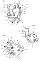
- Fig. 1 shows a connection cover 7 in the form of a molded plastic material with baffle 8.
- the connection cover 7 serves as a connection element for a small electric motor having axially aligned terminal lugs, which are contacted by motor contact areas 9 of the connection cover 7.
- the motor contact regions 9 are arranged in a flat region 21 of the connection cover 7, which has a recess 22 between the motor contact regions 9, which serves as a cutout for a bearing neck of the small electric motor 6.
- the areal region 21 is partially bounded by a wall 16 which is interrupted several times and which is configured as a centering device for the miniature electric motor 6.
- the wall 17 consists of three partial areas, so that the miniature electric motor 6 is held in all radial directions.
- the height of the walls 17 is limited in order not to spatially overlap with a housing of an actuator.
- the baffle 8 has at the edge of the connection cover 7 retaining portions 11, which consist of two opposing metal tabs, which leave a gap 23 which is provided for receiving Gescouseanformungen.
- the gaps 23 on both sides of the terminal cover 7 are perpendicular to the tabs bounded by spacers 16; These serve to guide and center the connection cover to the housing of the actuator. To the outside, the gaps 23 are not additionally limited. However, it would also be conceivable to provide an additional guide bar here.
- the baffle 8 further comprises contact arms 14, at the ends there are contacts 13, which serve as terminals for a contact surface of a printed circuit board.
- plate-like protective devices 15 on both sides of the contact arms 14 mitgeformt with the plastic material of the connection cover 7.
- Two protection devices 15 are arranged on the outer regions of the connection cover 7 and a protective device 15 is formed between the contact arms.
- Fig. 2 shows the baffle 8, which consists of two galvanically separated partial plates in the installed state. Before encapsulation, both partial sheets are connected to one another by metal bridges, which are then punched out or separated. Here it can be clearly seen that the motor contact areas 9 and the holding areas 11 lie in the same sheet metal plane. From the sheet plane, the contact arms 14 are angled several times with the contacts 13.
- Fig. 3 shows the connection cover 7 from a different perspective.
- the motor contact areas 9 have been cleared during encapsulation by cylindrical tool punches. Next are shown: the contact arms 14 with the contacts 13, the protection device 15, the wall 17, the holding areas 11 and the spacers 16.
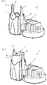
- Fig. 4 shows the housing 2 of the actuator 1, with a motor mount 3, which is adapted to the shape of a flattened miniature electric motor. Within the motor mount scraper ribs 24 are provided, whereby a radial backlash-free recording of the small electric motor is achieved. To a housing 25 of the motor mount 3 close two Gepurformept 12, which are provided as a mechanical receptacle for the connection cover. Radial to the engine mount 3 includes a housing portion which forms a transmission receptacle.
- Fig. 5 the electric miniature motor 6 is inserted without connection cover in the motor mount of the housing 2.
- the miniature electric motor has two axially projecting terminal lugs 10.
- the GeHouseanformungen 12 and the terminal lugs 10 are aligned parallel to each other.
- the order of installation is not mandatory. It is possible first to press the small electric motor into the motor mount and then to mount the connection cover 7, or first to form an assembly of the ultra-small electric motor and connection cover, which is then installed in the housing.
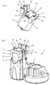
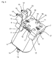
- Fig. 6 and 8th show such an assembly, which consists of the miniature electric motor 6 and the connection cover 7.
- the terminal lugs 10 of the miniature electric motor 6 are already clawed to the motor contact areas 9 of the terminal cover 7 and thus primarily electrically but also mechanically connected.
- the spacers 16, the wall 17, the protection device 15 and the contact arms 14th are already clawed to the motor contact areas 9 of the terminal cover 7 and thus primarily electrically but also mechanically connected.
- Fig. 7 is the assembly out of the FIGS. 6 and 8th mechanically connected via the Gepuruseanformungen 12 with the housing 2.
- the length of the Gepurformept 12 are designed so that they project even when using a miniature electric motor with a located at the tolerance upper limit housing length, over the connection cover. As a result, always a secure mechanical connection can be produced.
- the housing formations 12 occupy the space which is partially defined by the tabs of the support portion 11 and at right angles thereto by the associated spacer 16.
- the miniature electric motor 6 is radially radially centered and held by the wall 17 of the connection cover 7.
- the contact arms 14 and the protection device 15 are shown.
- Fig. 8 shows Fig. 6 in an enlarged view.
- a concave groove 20 can be seen on the tabs of the holding portion 11, which ensure that the GeHouseanformungen having a matching convex shape can be radially held better.
- the spacers 16 are provided. These dilate the slightly inclined housing formations on.
- the miniature electric motor has a motor shaft 19 with a pinion 18 fixed thereon.
- the pinion 18 is gearingly engaged with a reduction gear.
- Fig. 9 shows the gear box 4 of the housing 2 of the actuator 1, with the reduction gear 5 arranged therein, which is formed here by a multi-stage spur gear.
- the output stage of the transmission forms a spindle gear with respect to a gear secured against rotation threaded spindle 26th ,
Landscapes
- Engineering & Computer Science (AREA)
- Power Engineering (AREA)
- Microelectronics & Electronic Packaging (AREA)
- Motor Or Generator Frames (AREA)
- Connection Of Motors, Electrical Generators, Mechanical Devices, And The Like (AREA)
Description
- Die Erfindung betrifft einen Stellantrieb mit einem Gehäuse, das Aufnahmen für ein Untersetzungsgetriebe und für einen Elektrokleinstmotor umfasst, wobei die Motoraufnahme mit einem Anschlussdeckel verbunden ist.
- Aus der
US 2011/0166512 A1 ist ein gattungsgemäßer Stellantrieb bekannt, welcher als Antrieb für einen Kolben eines Medikamentenverabreichungsgeräts dient, womit eine langsame, fein dosierte Medikamentenabgabe vorgenommen wird. Die Aufnahme für den Elektrokleinstmotor ist hier durch eine Schnappverbindung gelöst, die zwischen dem Anschlussdeckel und dem Gehäuse hergestellt ist. Diese Schnappverbindung bedarf einer sehr engen Tolerierung, um ein Spiel zwischen dem Elektrokleinstmotor und dem Gehäuse zu begrenzen. Da das Untersetzungsgetriebe aufgrund der geringen Baugröße und des hohen Untersetzungsverhältnisses mit einer sehr feinen Verzahnung versehen ist und der Elektrokleinstmotor als Massenartikel mit einer relativ großen äußeren Maßtoleranz behaftet ist, kann die Verzahnung des Untersetzungsgetriebes zwischen einem Motorritzel und einem Getrieberad bei ungünstiger Teilekombination außer Eingriff geraten und das Gerät somit unbrauchbar sein. -
EP 1 191 210 A1 offenbart einen Stellantrieb mit einem umspritzten Leitblech. - Aufgabe der vorliegenden Erfindung ist es daher, bei einem gattungsgemäßen Stellantrieb für eine sichere spielfreie Aufnahme des Elektrokleinstmotors, sowie eine einfache Montage und Herstellbarkeit der verwendeten Teile bei hoher Wirtschaftlichkeit zu sorgen.
- Diese Aufgabe wird erfindungsgemäß durch das Kennzeichen des Anspruchs 1 gelöst. Die Motorkontaktbereiche des Anschlussdeckels dienen zur sicheren und einfachen Kontaktierung von Anschlussfahnen des Elektrokleinstmotors, welche sich achsparallel aus dessen Stirnseite erstrecken. Die Haltebereiche des Leitblechs dienen dazu, sich mit Gehäuseanformungen des Gehäuses zu verkrallen. Die Lage des Anschlussdeckels relativ zum Gehäuse ist dabei lediglich von der Motorlänge abhängig. Die Aufnahme des Elektrokleinstmotors im Gehäuse erfolgt auch bei unterschiedlicher Motorlänge stets spielfrei, weil der Anschlussdeckel bei der Montage auf Anschlag montiert wird. Dieser Vorgang lässt sich einfach automatisieren. Hierdurch lassen sich Motoren aus der Massenproduktion verwenden, die eine hohe Wirtschaftlichkeit erlauben.
- Weiterbildungen der Erfindung werden anhand der Unteransprüche dargestellt. Es ist vorgesehen, dass die Fügerichtung des Leitblechs in Bezug auf die Anschlussfahnen parallel zur Fügerichtung des Leitblechs in Bezug auf die Gehäuseanformungen ist. Hierdurch können in einem Arbeitsgang und mit einer Fügebewegung die elektrische Verbindung des Elektrokleinstmotors als auch die mechanische Verbindung des Anschlussdeckels mit dem Gehäuse des Stellantriebs und damit die mechanische Befestigung des Elektrokleinstmotors hergestellt werden.
- Um auch eine radiale Festsetzung des Elektrokleinstmotors im Gehäuse zu erzielen sind Schaberippen in der Aufnahme des Gehäuses vorgesehen, welche den Elektrokleinstmotor radial spielfrei halten, die aber bei dessen Übermaß auch abgeschabt oder deformiert werden können.
- In einer besonders bevorzugten Weiterbildung der Erfindung ist vorgesehen, dass die Gehäuseanformungen in Form von schmalen Zungen an die Aufnahme für den Elektrokleinstmotor anschließen und im montierten Zustand auch an der Toleranzobergrenze für die Gehäuselänge des Elektrokleinstmotors über den Anschlussdeckel vorspringen. Hierdurch kann der Elektrokleinstmotor durch den Anschlussdeckel über einen großen Toleranzbereich axial spielfrei und sicher in der Aufnahme gehalten werden.
- Vorteilhafterweise sollen die Kontakte des Anschlussdeckels in Form von federnden Kontaktarmen ausgebildet sein, wodurch eine einfache Montage gewährleistet ist und ein gewisser Toleranzausgleich erreicht wird.
- Damit diese Kontakte nicht im Produktionsprozess verbogen werden, sind an dem Kunststoffmaterial, das um das Leitblech gespritzt ist, Schutzeinrichtungen vorgesehen, welche beiderseits der Kontaktarme angeordnet sind. Die Kontaktarme erstrecken sich dabei im Wesentlichen radial zur Motorachse aus dem Anschlussdeckel; das gleiche gilt auch für die Schutzeinrichtungen, die plattenartig jeweils an den Enden des Anschlussdeckels beiderseits der Kontaktarme angeordnet sind und eine zusätzliche Schutzeinrichtung, die parallel zu den äußeren Schutzeinrichtungen zwischen den Kontaktarmen angeordnet ist.
- Eine besonders bevorzugte Weiterbildung der Erfindung wird durch Vorsprünge dargestellt, welche nahe der Haltebereiche als Abstandhalter für die Gehäuseanformungen des Gehäuses dienen. Die Gehäuseanformungen neigen sich tendenziell leicht nach innen zum Elektrokleinstmotor hin, so dass sie sich nicht in der optimalen Position bezüglich der Haltebereiche befinden. Die Haltebereiche sind Blechlaschen, die Bestandteil des umspritzten Leitblechs sind; sie bestehen jeweils aus zwei sich gegenüberstehenden Blechlaschen, die leicht schräggestellt sind, um einerseits das Fügen auf die Gehäuseanformungen zu erleichtern und andererseits das Lösen von diesen zu verhindern. Die Blechlaschen sind im Berührungsbereich mit den Gehäusanformungen leicht konkav ausgebildet, so dass sie an die leicht konvex gestalteten Gehäuseanformungen angepasst sind. Diese Formgebung ergibt, dass die radiale Lage der Gehäuseanformungen ein Optimum hat, welches durch die Abstandhalter erreicht wird.
- Zweckmäßigerweise weist der Anschlussdeckel eine Wandung auf, welche das Ende des Elektrokleinstmotors an zumindest drei Stellen radial umgreift. Diese Wandung soll verhindern, dass der Anschlussdeckel radial nur über die Motorkontaktbereiche gehalten ist, welche mit Ausnahme der konkaven Form ähnlich gestaltet sind und in der gleichen Richtung vorgebogen sind, wie die Haltebereiche. Die Wandung dient zur radialen Zentrierung des Elektrokleinstmotors in Bezug auf den Anschlussdeckel. Der Anschlussdeckel wiederum wird über die Gehäuseanformungen in Bezug auf die Motoraufnahme zentriert.
- Ein Ausführungsbeispiel der Erfindung wird nachfolgend anhand der Zeichnung näher erläutert. Es zeigen:
-
Fig. 1 einen Anschlussdeckel, -
Fig. 2 ein zweiteiliges Leitblech als Bestandteil des Anschlussdeckels, -
Fig. 3 eine zweite Ansicht des Anschlussdeckels, -
Fig. 4 ein Gehäuse eines Stellantriebs, -
Fig. 5 das Gehäuse mit eingebautem Elektrokleinstmotor, -
Fig. 6 den Elektrokleinstmotor mit vormontiertem Anschlussdeckel als Baugruppe, -
Fig. 7 die Baugruppe ausFig. 6 im eingebauten Zustand im Gehäuse, -
Fig. 8 eine vergrößerte Ansicht vonFig. 6 , -
Fig. 9 ein Untersetzungsgetriebe des Stellantriebs. -
Fig. 1 zeigt einen Anschlussdeckel 7 in Form eines mit Kunststoffmaterial umspritzten Leitblechs 8. Der Anschlussdeckel 7 dient als Anschlusselement für einen Elektrokleinstmotor, welcher axial ausgerichtete Anschlussfahnen aufweist, die durch Motorkontaktbereiche 9 des Anschlussdeckels 7 kontaktierbar sind. Die Motorkontaktbereiche 9 sind in einem flächigen Bereich 21 des Anschlussdeckels 7 angeordnet, welcher zwischen den Motorkontaktbereichen 9 einen Rücksprung 22 aufweist, der als Freisparung für einen Lageransatz des Elektrokleinstmotors 6 dient. Der flächige Bereich 21 wird teilweise berandet durch eine mehrfach unterbrochene Wandung 17, welche als Zentriermittel für den Elektrokleinstmotor 6 ausgestaltet ist. Im gezeigten Beispiel besteht die Wandung 17 aus drei Teilbereichen, so dass der Elektrokleinstmotor 6 in alle radialen Richtungen gehalten wird. Die Höhe der Wandungen 17 ist begrenzt, um sich räumlich nicht mit einem Gehäuse eines Stellantriebs zu überschneiden. Das Leitblech 8 weist am Rand des Anschlussdeckels 7 Haltebereiche 11 auf, welche aus zwei einander gegenüberliegenden Blechlaschen bestehen, welche einen Zwischenraum 23 belassen, der zur Aufnahme von Gehäuseanformungen vorgesehen ist. Die Zwischenräume 23 auf beiden Seiten der Anschlussdeckels 7 sind rechtwinklig zu den Laschen durch Abstandhalter 16 begrenzt; diese dienen zur Führung und Zentrierung des Anschlussdeckels zum Gehäuse des Stellantriebs. Nach Außen sind die Zwischenräume 23 nicht zusätzlich begrenzt. Es wäre aber denkbar auch hier einen zusätzlichen Führungssteg vorzusehen. Das Leitblech 8 weist weiter Kontaktarme 14 auf, an deren Enden sich Kontakte 13 befinden, die als Anschlüsse für eine Kontaktfläche einer Leiterplatte dienen. Um die Kontaktarme insbesondere während des Fertigungsprozesses gegen Verformungen zu schützen, sind plattenartige Schutzeinrichtungen 15 beiderseits der Kontaktarme 14 mit dem Kunststoffmaterial des Anschlussdeckels 7 mitgeformt. Zwei Schutzeinrichtungen 15 sind an den Außenbereichen des Anschlussdeckels 7 angeordnet und eine Schutzeinrichtung 15 ist zwischen den Kontaktarmen ausgebildet. -
Fig. 2 zeigt das Leitblech 8, das im Einbauzustand aus zwei galvanisch voneinander getrennten Teilblechen besteht. Vor dem Umspritzen sind beide Teilbleche durch Blechbrücken miteinander verbunden, die anschließend ausgestanzt oder aufgetrennt werden. Hier ist deutlich zu erkennen, dass die Motorkontaktbereiche 9 und die Haltebereiche 11 in der gleichen Blechebene liegen. Aus der Blechebene sind die Kontaktarme 14 mit den Kontakten 13 mehrfach abgewinkelt. -
Fig. 3 zeigt den Anschlussdeckel 7 aus einer anderen Perspektive. Um die Motorkontaktbereiche 9 nutzbar zu machen, sind sie beim Umspritzen durch zylindrische Werkzeugstempel freigespart worden. Weiter sind dargestellt: die Kontaktarme 14 mit den Kontakten 13, die Schutzeinrichtung 15, die Wandung 17, die Haltebereiche 11 und die Abstandhalter 16. -
Fig. 4 zeigt das Gehäuse 2 des Stellantriebs 1, mit einer Motoraufnahme 3, die der Form eines abgeflachten Elektrokleinstmotors angepasst ist. Innerhalb der Motoraufnahme sind Schaberippen 24 vorgesehen, wodurch eine radial spielfreie Aufnahme des Elektrokleinstmotors erreicht wird. An eine Gehäusewandung 25 der Motoraufnahme 3 schließen zwei Gehäuseanformungen 12 an, die als mechanische Aufnahme für den Anschlussdeckel vorgesehen sind. Radial zur Motoraufnahme 3 schließt ein Gehäusebereich an, der eine Getriebeaufnahme bildet. - In
Fig. 5 ist der Elektrokleinstmotor 6 ohne Anschlussdeckel in der Motoraufnahme des Gehäuses 2 eingelegt. Der Elektrokleinstmotor weist zwei axial vorspringende Anschlussfahnen 10 auf. Die Gehäuseanformungen 12 und die Anschlussfahnen 10 sind parallel zueinander ausgerichtet. Die Montagereihenfolge ist nicht zwingend vorgegeben. Es ist möglich, den Elektrokleinstmotor zuerst in die Motoraufnahme einzupressen und den Anschlussdeckel 7 anschließend zu montieren, oder zunächst eine Baugruppe aus Elektrokleinstmotor und Anschlussdeckel zu bilden, welche anschließend in das Gehäuse eingebaut wird. -
Fig. 6 und8 zeigen eine derartige Baugruppe, die aus dem Elektrokleinstmotor 6 und dem Anschlussdeckel 7 besteht. Hier sind die Anschlussfahnen 10 des Elektrokleinstmotors 6 bereits mit den Motorkontaktbereichen 9 des Anschlussdeckels 7 verkrallt und damit in erster Linie elektrisch aber auch mechanisch verbunden. Weiter sind zu erkennen die Abstandhalter 16, die Wandung 17, die Schutzeinrichtung 15 und die Kontaktarme 14. - In
Fig. 7 ist die Baugruppe aus denFiguren 6 und8 über die Gehäuseanformungen 12 mit dem Gehäuse 2 mechanisch verbunden. Die Länge der Gehäuseanformungen 12 sind so ausgelegt, dass sie auch bei Verwendung eines Elektrokleinstmotors mit einer sich an der Toleranzobergrenze befindlichen Gehäuselänge, über den Anschlussdeckel vorspringen. Dadurch ist stets eine sichere mechanische Verbindung herstellbar. Die Gehäuseanformungen 12 nehmen den Zwischenraum ein, der teilweise von den Laschen des Haltebereichs 11 und rechtwinklig hierzu von dem zugeordneten Abstandhalter 16 definiert wird. Der Elektrokleinstmotor 6 wird radial auch durch die Wandung 17 des Anschlussdeckels 7 radial zentriert und gehalten. Weiter sind die Kontaktarme 14 und die Schutzeinrichtung 15 dargestellt. -
Fig. 8 zeigtFig. 6 in einer vergrößerten Darstellung. Hier ist zusätzlich eine konkave Auskehlung 20 an den Laschen des Haltebereichs 11 zu erkennen, welche dafür sorgen, dass die Gehäuseanformungen, welche eine dazu passende konvexe Gestalt aufweisen radial besser gehalten werden können. Damit diese zueinander passenden Formen sich leichter finden können, sind die Abstandhalter 16 vorgesehen. Diese weiten die einander leicht zugeneigten Gehäuseanformungen auf. Der Elektrokleinstmotor weist eine Motorwelle 19 mit einem darauf festsitzenden Ritzel 18 auf. Das Ritzel 18 ist mit einem Untersetzungsgetriebe getrieblich in Eingriff. -
Fig. 9 zeigt die Getriebeaufnahme 4 des Gehäuses 2 des Stellantriebs 1, mit dem darin angeordneten Untersetzungsgetriebe 5, das hier von einem mehrstufigen Stirnradgetriebe gebildet wird. Weiter zu erkennen sind der Elektrokleinstmotor 6, der Anschlussdeckel 7, das Leitblech 8, die Gehäuseanformungen 12, die Motorwelle 19 und das mit dem Untersetzungsgetriebe getrieblich in Eingriff befindliche Ritzel 18. Die Endstufe des Getriebes bildet ein Spindelgetriebe mit einer gegenüber einem Zahnrad verdrehgesicherten Gewindespindel 26. -
- 1
- Stellantrieb
- 2
- Gehäuse
- 3
- Motoraufnahme
- 4
- Getriebeaufnahme
- 5
- Untersetzungsgetriebe
- 6
- Elektrokleinstmotor
- 7
- Anschlussdeckel
- 8
- Leitblech
- 9
- Motorkontaktbereich
- 10
- Anschlussfahne
- 11
- Haltebereich
- 12
- Gehäuseanformung
- 13
- Kontakt
- 14
- Kontaktarm
- 15
- Schutzeinrichtung
- 16
- Abstandhalter
- 17
- Wandung
- 18
- Ritzel
- 19
- Motorwelle
- 20
- Auskehlung
- 21
- flächiger Bereich
- 22
- Rücksprung
- 23
- Zwischenraum
- 24
- Schaberippe
- 25
- Gehäusewandung
- 26
- Gewindespindel
Claims (9)
- Stellantrieb (1) mit einem Gehäuse (2), das Aufnahmen (3, 4) für ein Untersetzungsgetriebe (5) und für einen Elektrokleinstmotor (6) umfasst, wobei die Motoraufnahme (3) mit einem Anschlussdeckel (7) verbunden ist, wobei der Anschlussdeckel (7) aus einem mit Kunststoffmaterial umspritzten Leitblech (8) besteht, das Motorkontaktbereiche (9) aufweist, die sich mit Anschlussfahnen (10) des Elektrokleinstmotors verkrallen, dadurch gekennzeichnet, dass das Leitblech (8) Haltebereiche (11) aufweist, die sich mit Gehäuseanformungen (12) des Gehäuses (2) verkrallen.
- Stellantrieb nach Anspruch 1, dadurch gekennzeichnet, dass die Fügerichtung des Leitblechs (8) in Bezug auf die Anschlussfahnen (10) parallel zur Fügerichtung des Leitblechs (8) in Bezug auf die Gehäuseanformungen (12) ist.
- Stellantrieb nach Anspruch 1 oder 2, dadurch gekennzeichnet, dass der Elektrokleinstmotor (6) mit Hilfe von Schaberippen (24) in der Aufnahme (3) des Gehäuses (2) zumindest radial fest gehalten ist.
- Stellantrieb nach Anspruch 1, 2 oder 3, dadurch gekennzeichnet, dass die Gehäuseanformungen (12) in Form von schmalen Zungen an die Aufnahme (3) für den Elektrokleinstmotor anschließen und im montierten Zustand auch an der Toleranzobergrenze für die Gehäuselänge des Elektrokleinstmotors über den Anschlussdeckel (7) vorspringen, so dass der Elektrokleinstmotor (6) durch den Anschlussdeckel (7) über einen großen Toleranzbereich axial spielfrei in der Aufnahme (3) gehalten ist.
- Stellantrieb nach Anspruch 1, 2, 3 oder 4, dadurch gekennzeichnet, dass das Leitblech (8) mit Kontakten (13) zur Verbindung mit einer Elektronik und/oder einer Spannungsversorgung einstückig ist.
- Stellantrieb nach Anspruch 5, dadurch gekennzeichnet, dass die Kontakte (13) in Form von federnden Kontaktarmen (14) ausgebildet sind.
- Stellantrieb nach zumindest einem der vorangehenden Ansprüche, dadurch gekennzeichnet, dass das Kunststoffmaterial, das um das Leitblech (8) gespritzt ist, Schutzeinrichtungen (15) umfasst, welche beiderseits der Kontaktarme (14) angeordnet sind.
- Stellantrieb nach zumindest einem der vorangehenden Ansprüche, dadurch gekennzeichnet, dass der Anschlussdeckel (7) nahe der Haltebereiche (11) Abstandhalter (16) in Form von Vorsprüngen aufweist.
- Stellantrieb nach zumindest einem der vorangehenden Ansprüche, dadurch gekennzeichnet, dass der Anschlussdeckel (7) eine Wandung (17) aufweist, welche das Ende des Elektrokleinstmotors (6) an zumindest drei Stellen radial umgreift.
Applications Claiming Priority (2)
| Application Number | Priority Date | Filing Date | Title |
|---|---|---|---|
| DE102011084341.8A DE102011084341B4 (de) | 2011-10-12 | 2011-10-12 | Stellantrieb |
| PCT/DE2012/200068 WO2013053357A2 (de) | 2011-10-12 | 2012-10-12 | Stellantrieb |
Publications (2)
| Publication Number | Publication Date |
|---|---|
| EP2766977A2 EP2766977A2 (de) | 2014-08-20 |
| EP2766977B1 true EP2766977B1 (de) | 2016-04-27 |
Family
ID=47191459
Family Applications (1)
| Application Number | Title | Priority Date | Filing Date |
|---|---|---|---|
| EP12787639.9A Not-in-force EP2766977B1 (de) | 2011-10-12 | 2012-10-12 | Stellantrieb |
Country Status (5)
| Country | Link |
|---|---|
| US (1) | US9391484B2 (de) |
| EP (1) | EP2766977B1 (de) |
| CN (1) | CN103891107B (de) |
| DE (1) | DE102011084341B4 (de) |
| WO (1) | WO2013053357A2 (de) |
Families Citing this family (5)
| Publication number | Priority date | Publication date | Assignee | Title |
|---|---|---|---|---|
| DE102016101963A1 (de) * | 2016-02-04 | 2017-08-10 | Bühler Motor GmbH | Elektromotor für eine Fluidpumpe, modulare Motorfamilie zur Bildung unterschiedlicher Fluidpumpen mit mehreren solcher Elektromotoren und Herstellungsverfahren |
| DE102016117965A1 (de) * | 2016-09-23 | 2018-03-29 | Trw Automotive Gmbh | Gurtaufrollerbaugruppe für ein Insassenrückhaltesystem sowie Verfahren zur Montage einer solchen Gurtaufrollerbaugruppe |
| JP6849906B2 (ja) * | 2016-11-02 | 2021-03-31 | 株式会社今仙電機製作所 | モータユニットおよびパワーシート装置 |
| CN111371239A (zh) * | 2020-03-13 | 2020-07-03 | 贵州华烽汽车零部件有限公司 | 汽车空气循环系统控制机构电机电源接线端改进结构 |
| CN114727526A (zh) * | 2022-04-08 | 2022-07-08 | 南京元朗电子科技发展有限公司 | 一种冲压件、控制器壳体及控制器 |
Family Cites Families (12)
| Publication number | Priority date | Publication date | Assignee | Title |
|---|---|---|---|---|
| DE4215463C2 (de) * | 1992-05-11 | 1994-09-01 | Wacker Werke Kg | Rüttler mit eingebautem Elektromotor |
| US5354214A (en) * | 1993-07-23 | 1994-10-11 | Molex Incorporated | Printed circuit board electrical connector with mounting latch clip |
| GB9323932D0 (en) * | 1993-11-20 | 1994-01-05 | Johnson Electric Sa | Splashproof cover for a miniature electric motor |
| WO2000068556A1 (en) * | 1999-05-10 | 2000-11-16 | Hitachi, Ltd. | Throttle device of internal combustion engine |
| DE10101608B4 (de) * | 2001-01-16 | 2007-10-18 | Bühler Motor GmbH | Stellantrieb |
| DE10130118C2 (de) * | 2001-06-22 | 2003-05-08 | Minebea Co Ltd | Trägervorrichtung für einen Elektromotor, insbesondere für einen elektronisch kommunitierten Gleichstrommotor |
| JP4031351B2 (ja) * | 2002-11-08 | 2008-01-09 | アスモ株式会社 | アクチュエータ装置 |
| DE102004063814A1 (de) * | 2004-12-30 | 2006-07-13 | Kiekert Ag | Adapter zur Verwendung mit einem elektronischen Kleinstantrieb |
| US8657031B2 (en) * | 2005-10-12 | 2014-02-25 | Black & Decker Inc. | Universal control module |
| JP4735197B2 (ja) * | 2005-11-04 | 2011-07-27 | 株式会社デンソー | モータアクチュエータ |
| JP5173668B2 (ja) * | 2008-08-18 | 2013-04-03 | 株式会社ミツバ | 減速機構付モータ |
| US8303535B2 (en) * | 2008-09-10 | 2012-11-06 | Hoffman-La Roche Inc. | Delivery device for use with a therapeutic drug |
-
2011
- 2011-10-12 DE DE102011084341.8A patent/DE102011084341B4/de not_active Expired - Fee Related
-
2012
- 2012-10-12 WO PCT/DE2012/200068 patent/WO2013053357A2/de not_active Ceased
- 2012-10-12 EP EP12787639.9A patent/EP2766977B1/de not_active Not-in-force
- 2012-10-12 CN CN201280044484.9A patent/CN103891107B/zh not_active Expired - Fee Related
-
2014
- 2014-02-04 US US14/172,411 patent/US9391484B2/en not_active Expired - Fee Related
Also Published As
| Publication number | Publication date |
|---|---|
| US20140152132A1 (en) | 2014-06-05 |
| CN103891107A (zh) | 2014-06-25 |
| US9391484B2 (en) | 2016-07-12 |
| CN103891107B (zh) | 2016-10-19 |
| DE102011084341A1 (de) | 2013-04-18 |
| WO2013053357A3 (de) | 2014-06-12 |
| EP2766977A2 (de) | 2014-08-20 |
| WO2013053357A2 (de) | 2013-04-18 |
| DE102011084341B4 (de) | 2017-07-06 |
Similar Documents
| Publication | Publication Date | Title |
|---|---|---|
| EP3217483B1 (de) | Halterahmen für einen steckverbinder | |
| DE102013113976B4 (de) | Halterahmen für einen Steckverbinder | |
| EP3080874B2 (de) | Halterahmen für einen steckverbinder | |
| EP1095443A1 (de) | Stellantrieb mit einem elektromotor und mit einer steuerelektronik | |
| EP3613110B1 (de) | Baugruppe für ein steckverbinderteil mit einem kontakteinsatz und einem erdungselement | |
| EP1171680A1 (de) | Motorgehäuse und poltopf, insbesondere für fensterheber- oder schiebedachmotoren | |
| WO1988001802A1 (fr) | Machine electrique, notamment moteur electrique | |
| DE102011084341B4 (de) | Stellantrieb | |
| EP3480898A1 (de) | Modularer halterahmen für steckverbinder | |
| EP3488498B1 (de) | Halterahmenanordnung mit grundrahmen und fixierelement und bestückungsverfahren | |
| DE102014205744B4 (de) | Steuergerät für ein Fahrzeugheizgerät | |
| EP2636101B1 (de) | Elektrischer steckverbinder | |
| DE102010002862A1 (de) | Kontaktstecker, Antriebseinheit beinhaltend einen solchen, sowie Herstellungsverfahren einer Antriebseinheit | |
| EP1671399A1 (de) | Schirmanbindung | |
| EP2732509B1 (de) | Stecker und verfahren zu seiner herstellung | |
| EP1660763A1 (de) | Stellvorrichtung insbesondere für eine drosselklappe einer brennkraftmaschine | |
| EP1377765A1 (de) | Getriebe, insbesondere schneckengetriebe | |
| DE102007052896A1 (de) | Elektrischer Schalter | |
| EP2139096B1 (de) | Elektromotorischer Hilfsantrieb für Fahrzeuge | |
| EP2648285B1 (de) | Steckverbinder zur Montage in eine Gehäuseöffnung eines Gehäuses | |
| DE20107605U1 (de) | Elektrischer Verbinder | |
| EP2255430A2 (de) | Motor-getriebeeinheit sowie modulares system | |
| DE4126118A1 (de) | Rastverbindung zwischen einem motortopf und einem getriebegehaeuse | |
| EP4231463B1 (de) | Steckverbinder zur montage auf einer leiterplatte | |
| EP2267845A2 (de) | Elektrische Verbindungsanordnung |
Legal Events
| Date | Code | Title | Description |
|---|---|---|---|
| PUAI | Public reference made under article 153(3) epc to a published international application that has entered the european phase |
Free format text: ORIGINAL CODE: 0009012 |
|
| 17P | Request for examination filed |
Effective date: 20140204 |
|
| AK | Designated contracting states |
Kind code of ref document: A2 Designated state(s): AL AT BE BG CH CY CZ DE DK EE ES FI FR GB GR HR HU IE IS IT LI LT LU LV MC MK MT NL NO PL PT RO RS SE SI SK SM TR |
|
| DAX | Request for extension of the european patent (deleted) | ||
| GRAP | Despatch of communication of intention to grant a patent |
Free format text: ORIGINAL CODE: EPIDOSNIGR1 |
|
| INTG | Intention to grant announced |
Effective date: 20160111 |
|
| GRAS | Grant fee paid |
Free format text: ORIGINAL CODE: EPIDOSNIGR3 |
|
| GRAA | (expected) grant |
Free format text: ORIGINAL CODE: 0009210 |
|
| RIN1 | Information on inventor provided before grant (corrected) |
Inventor name: PETERREINS, THOMAS Inventor name: SACHNOV, WJATSCHESLAV |
|
| AK | Designated contracting states |
Kind code of ref document: B1 Designated state(s): AL AT BE BG CH CY CZ DE DK EE ES FI FR GB GR HR HU IE IS IT LI LT LU LV MC MK MT NL NO PL PT RO RS SE SI SK SM TR |
|
| REG | Reference to a national code |
Ref country code: GB Ref legal event code: FG4D Free format text: NOT ENGLISH |
|
| REG | Reference to a national code |
Ref country code: CH Ref legal event code: EP |
|
| REG | Reference to a national code |
Ref country code: AT Ref legal event code: REF Ref document number: 795758 Country of ref document: AT Kind code of ref document: T Effective date: 20160515 |
|
| REG | Reference to a national code |
Ref country code: IE Ref legal event code: FG4D Free format text: LANGUAGE OF EP DOCUMENT: GERMAN |
|
| REG | Reference to a national code |
Ref country code: DE Ref legal event code: R096 Ref document number: 502012006951 Country of ref document: DE |
|
| REG | Reference to a national code |
Ref country code: SE Ref legal event code: TRGR |
|
| REG | Reference to a national code |
Ref country code: LT Ref legal event code: MG4D |
|
| REG | Reference to a national code |
Ref country code: NL Ref legal event code: MP Effective date: 20160427 |
|
| REG | Reference to a national code |
Ref country code: FR Ref legal event code: PLFP Year of fee payment: 5 |
|
| PG25 | Lapsed in a contracting state [announced via postgrant information from national office to epo] |
Ref country code: NL Free format text: LAPSE BECAUSE OF FAILURE TO SUBMIT A TRANSLATION OF THE DESCRIPTION OR TO PAY THE FEE WITHIN THE PRESCRIBED TIME-LIMIT Effective date: 20160427 |
|
| PG25 | Lapsed in a contracting state [announced via postgrant information from national office to epo] |
Ref country code: LT Free format text: LAPSE BECAUSE OF FAILURE TO SUBMIT A TRANSLATION OF THE DESCRIPTION OR TO PAY THE FEE WITHIN THE PRESCRIBED TIME-LIMIT Effective date: 20160427 Ref country code: NO Free format text: LAPSE BECAUSE OF FAILURE TO SUBMIT A TRANSLATION OF THE DESCRIPTION OR TO PAY THE FEE WITHIN THE PRESCRIBED TIME-LIMIT Effective date: 20160727 Ref country code: PL Free format text: LAPSE BECAUSE OF FAILURE TO SUBMIT A TRANSLATION OF THE DESCRIPTION OR TO PAY THE FEE WITHIN THE PRESCRIBED TIME-LIMIT Effective date: 20160427 Ref country code: FI Free format text: LAPSE BECAUSE OF FAILURE TO SUBMIT A TRANSLATION OF THE DESCRIPTION OR TO PAY THE FEE WITHIN THE PRESCRIBED TIME-LIMIT Effective date: 20160427 |
|
| PG25 | Lapsed in a contracting state [announced via postgrant information from national office to epo] |
Ref country code: ES Free format text: LAPSE BECAUSE OF FAILURE TO SUBMIT A TRANSLATION OF THE DESCRIPTION OR TO PAY THE FEE WITHIN THE PRESCRIBED TIME-LIMIT Effective date: 20160427 Ref country code: HR Free format text: LAPSE BECAUSE OF FAILURE TO SUBMIT A TRANSLATION OF THE DESCRIPTION OR TO PAY THE FEE WITHIN THE PRESCRIBED TIME-LIMIT Effective date: 20160427 Ref country code: PT Free format text: LAPSE BECAUSE OF FAILURE TO SUBMIT A TRANSLATION OF THE DESCRIPTION OR TO PAY THE FEE WITHIN THE PRESCRIBED TIME-LIMIT Effective date: 20160829 Ref country code: RS Free format text: LAPSE BECAUSE OF FAILURE TO SUBMIT A TRANSLATION OF THE DESCRIPTION OR TO PAY THE FEE WITHIN THE PRESCRIBED TIME-LIMIT Effective date: 20160427 Ref country code: GR Free format text: LAPSE BECAUSE OF FAILURE TO SUBMIT A TRANSLATION OF THE DESCRIPTION OR TO PAY THE FEE WITHIN THE PRESCRIBED TIME-LIMIT Effective date: 20160728 Ref country code: LV Free format text: LAPSE BECAUSE OF FAILURE TO SUBMIT A TRANSLATION OF THE DESCRIPTION OR TO PAY THE FEE WITHIN THE PRESCRIBED TIME-LIMIT Effective date: 20160427 |
|
| REG | Reference to a national code |
Ref country code: DE Ref legal event code: R097 Ref document number: 502012006951 Country of ref document: DE |
|
| PG25 | Lapsed in a contracting state [announced via postgrant information from national office to epo] |
Ref country code: CZ Free format text: LAPSE BECAUSE OF FAILURE TO SUBMIT A TRANSLATION OF THE DESCRIPTION OR TO PAY THE FEE WITHIN THE PRESCRIBED TIME-LIMIT Effective date: 20160427 Ref country code: EE Free format text: LAPSE BECAUSE OF FAILURE TO SUBMIT A TRANSLATION OF THE DESCRIPTION OR TO PAY THE FEE WITHIN THE PRESCRIBED TIME-LIMIT Effective date: 20160427 Ref country code: SK Free format text: LAPSE BECAUSE OF FAILURE TO SUBMIT A TRANSLATION OF THE DESCRIPTION OR TO PAY THE FEE WITHIN THE PRESCRIBED TIME-LIMIT Effective date: 20160427 Ref country code: RO Free format text: LAPSE BECAUSE OF FAILURE TO SUBMIT A TRANSLATION OF THE DESCRIPTION OR TO PAY THE FEE WITHIN THE PRESCRIBED TIME-LIMIT Effective date: 20160427 Ref country code: DK Free format text: LAPSE BECAUSE OF FAILURE TO SUBMIT A TRANSLATION OF THE DESCRIPTION OR TO PAY THE FEE WITHIN THE PRESCRIBED TIME-LIMIT Effective date: 20160427 |
|
| PG25 | Lapsed in a contracting state [announced via postgrant information from national office to epo] |
Ref country code: SM Free format text: LAPSE BECAUSE OF FAILURE TO SUBMIT A TRANSLATION OF THE DESCRIPTION OR TO PAY THE FEE WITHIN THE PRESCRIBED TIME-LIMIT Effective date: 20160427 Ref country code: BE Free format text: LAPSE BECAUSE OF NON-PAYMENT OF DUE FEES Effective date: 20161031 |
|
| PLBE | No opposition filed within time limit |
Free format text: ORIGINAL CODE: 0009261 |
|
| STAA | Information on the status of an ep patent application or granted ep patent |
Free format text: STATUS: NO OPPOSITION FILED WITHIN TIME LIMIT |
|
| 26N | No opposition filed |
Effective date: 20170130 |
|
| PG25 | Lapsed in a contracting state [announced via postgrant information from national office to epo] |
Ref country code: SI Free format text: LAPSE BECAUSE OF FAILURE TO SUBMIT A TRANSLATION OF THE DESCRIPTION OR TO PAY THE FEE WITHIN THE PRESCRIBED TIME-LIMIT Effective date: 20160427 |
|
| REG | Reference to a national code |
Ref country code: CH Ref legal event code: PL |
|
| REG | Reference to a national code |
Ref country code: FR Ref legal event code: PLFP Year of fee payment: 6 |
|
| REG | Reference to a national code |
Ref country code: IE Ref legal event code: MM4A |
|
| PG25 | Lapsed in a contracting state [announced via postgrant information from national office to epo] |
Ref country code: LI Free format text: LAPSE BECAUSE OF NON-PAYMENT OF DUE FEES Effective date: 20161031 Ref country code: CH Free format text: LAPSE BECAUSE OF NON-PAYMENT OF DUE FEES Effective date: 20161031 |
|
| PG25 | Lapsed in a contracting state [announced via postgrant information from national office to epo] |
Ref country code: LU Free format text: LAPSE BECAUSE OF NON-PAYMENT OF DUE FEES Effective date: 20161012 |
|
| PG25 | Lapsed in a contracting state [announced via postgrant information from national office to epo] |
Ref country code: IE Free format text: LAPSE BECAUSE OF NON-PAYMENT OF DUE FEES Effective date: 20161012 |
|
| REG | Reference to a national code |
Ref country code: BE Ref legal event code: MM Effective date: 20161031 |
|
| PG25 | Lapsed in a contracting state [announced via postgrant information from national office to epo] |
Ref country code: HU Free format text: LAPSE BECAUSE OF FAILURE TO SUBMIT A TRANSLATION OF THE DESCRIPTION OR TO PAY THE FEE WITHIN THE PRESCRIBED TIME-LIMIT; INVALID AB INITIO Effective date: 20121012 |
|
| PG25 | Lapsed in a contracting state [announced via postgrant information from national office to epo] |
Ref country code: CY Free format text: LAPSE BECAUSE OF FAILURE TO SUBMIT A TRANSLATION OF THE DESCRIPTION OR TO PAY THE FEE WITHIN THE PRESCRIBED TIME-LIMIT Effective date: 20160427 Ref country code: MK Free format text: LAPSE BECAUSE OF FAILURE TO SUBMIT A TRANSLATION OF THE DESCRIPTION OR TO PAY THE FEE WITHIN THE PRESCRIBED TIME-LIMIT Effective date: 20160427 Ref country code: MT Free format text: LAPSE BECAUSE OF FAILURE TO SUBMIT A TRANSLATION OF THE DESCRIPTION OR TO PAY THE FEE WITHIN THE PRESCRIBED TIME-LIMIT Effective date: 20160427 Ref country code: MC Free format text: LAPSE BECAUSE OF FAILURE TO SUBMIT A TRANSLATION OF THE DESCRIPTION OR TO PAY THE FEE WITHIN THE PRESCRIBED TIME-LIMIT Effective date: 20160427 Ref country code: IS Free format text: LAPSE BECAUSE OF FAILURE TO SUBMIT A TRANSLATION OF THE DESCRIPTION OR TO PAY THE FEE WITHIN THE PRESCRIBED TIME-LIMIT Effective date: 20160427 |
|
| PG25 | Lapsed in a contracting state [announced via postgrant information from national office to epo] |
Ref country code: BG Free format text: LAPSE BECAUSE OF FAILURE TO SUBMIT A TRANSLATION OF THE DESCRIPTION OR TO PAY THE FEE WITHIN THE PRESCRIBED TIME-LIMIT Effective date: 20160427 |
|
| REG | Reference to a national code |
Ref country code: FR Ref legal event code: PLFP Year of fee payment: 7 |
|
| PG25 | Lapsed in a contracting state [announced via postgrant information from national office to epo] |
Ref country code: TR Free format text: LAPSE BECAUSE OF FAILURE TO SUBMIT A TRANSLATION OF THE DESCRIPTION OR TO PAY THE FEE WITHIN THE PRESCRIBED TIME-LIMIT Effective date: 20160427 Ref country code: AL Free format text: LAPSE BECAUSE OF FAILURE TO SUBMIT A TRANSLATION OF THE DESCRIPTION OR TO PAY THE FEE WITHIN THE PRESCRIBED TIME-LIMIT Effective date: 20160427 |
|
| PGFP | Annual fee paid to national office [announced via postgrant information from national office to epo] |
Ref country code: FR Payment date: 20200811 Year of fee payment: 9 |
|
| PGFP | Annual fee paid to national office [announced via postgrant information from national office to epo] |
Ref country code: GB Payment date: 20201026 Year of fee payment: 9 |
|
| PGFP | Annual fee paid to national office [announced via postgrant information from national office to epo] |
Ref country code: DE Payment date: 20201217 Year of fee payment: 9 |
|
| PGFP | Annual fee paid to national office [announced via postgrant information from national office to epo] |
Ref country code: SE Payment date: 20211018 Year of fee payment: 10 Ref country code: AT Payment date: 20211008 Year of fee payment: 10 |
|
| PGFP | Annual fee paid to national office [announced via postgrant information from national office to epo] |
Ref country code: IT Payment date: 20211006 Year of fee payment: 10 |
|
| REG | Reference to a national code |
Ref country code: DE Ref legal event code: R119 Ref document number: 502012006951 Country of ref document: DE |
|
| GBPC | Gb: european patent ceased through non-payment of renewal fee |
Effective date: 20211012 |
|
| PG25 | Lapsed in a contracting state [announced via postgrant information from national office to epo] |
Ref country code: GB Free format text: LAPSE BECAUSE OF NON-PAYMENT OF DUE FEES Effective date: 20211012 Ref country code: DE Free format text: LAPSE BECAUSE OF NON-PAYMENT OF DUE FEES Effective date: 20220503 |
|
| PG25 | Lapsed in a contracting state [announced via postgrant information from national office to epo] |
Ref country code: FR Free format text: LAPSE BECAUSE OF NON-PAYMENT OF DUE FEES Effective date: 20211031 |
|
| REG | Reference to a national code |
Ref country code: SE Ref legal event code: EUG |
|
| REG | Reference to a national code |
Ref country code: AT Ref legal event code: MM01 Ref document number: 795758 Country of ref document: AT Kind code of ref document: T Effective date: 20221012 |
|
| PG25 | Lapsed in a contracting state [announced via postgrant information from national office to epo] |
Ref country code: AT Free format text: LAPSE BECAUSE OF NON-PAYMENT OF DUE FEES Effective date: 20221012 |
|
| PG25 | Lapsed in a contracting state [announced via postgrant information from national office to epo] |
Ref country code: SE Free format text: LAPSE BECAUSE OF NON-PAYMENT OF DUE FEES Effective date: 20221013 |
|
| PG25 | Lapsed in a contracting state [announced via postgrant information from national office to epo] |
Ref country code: IT Free format text: LAPSE BECAUSE OF NON-PAYMENT OF DUE FEES Effective date: 20221012 |