EP2766687B1 - Stacked plate exhaust gas recovery device - Google Patents
Stacked plate exhaust gas recovery device Download PDFInfo
- Publication number
- EP2766687B1 EP2766687B1 EP12829797.5A EP12829797A EP2766687B1 EP 2766687 B1 EP2766687 B1 EP 2766687B1 EP 12829797 A EP12829797 A EP 12829797A EP 2766687 B1 EP2766687 B1 EP 2766687B1
- Authority
- EP
- European Patent Office
- Prior art keywords
- gas
- core
- liquid
- valve body
- heat exchanger
- Prior art date
- Legal status (The legal status is an assumption and is not a legal conclusion. Google has not performed a legal analysis and makes no representation as to the accuracy of the status listed.)
- Not-in-force
Links
- 238000011084 recovery Methods 0.000 title claims description 31
- 239000007788 liquid Substances 0.000 claims description 94
- 238000007789 sealing Methods 0.000 claims description 34
- 238000007373 indentation Methods 0.000 claims description 3
- 239000007789 gas Substances 0.000 description 152
- 239000002826 coolant Substances 0.000 description 19
- 238000001816 cooling Methods 0.000 description 6
- 230000008646 thermal stress Effects 0.000 description 6
- 238000010438 heat treatment Methods 0.000 description 5
- LYCAIKOWRPUZTN-UHFFFAOYSA-N Ethylene glycol Chemical compound OCCO LYCAIKOWRPUZTN-UHFFFAOYSA-N 0.000 description 4
- 239000012530 fluid Substances 0.000 description 3
- 229910001018 Cast iron Inorganic materials 0.000 description 2
- 230000008901 benefit Effects 0.000 description 2
- 230000005540 biological transmission Effects 0.000 description 2
- 238000005219 brazing Methods 0.000 description 2
- 230000000694 effects Effects 0.000 description 2
- 239000000446 fuel Substances 0.000 description 2
- WGCNASOHLSPBMP-UHFFFAOYSA-N hydroxyacetaldehyde Natural products OCC=O WGCNASOHLSPBMP-UHFFFAOYSA-N 0.000 description 2
- 229910052751 metal Inorganic materials 0.000 description 2
- 239000002184 metal Substances 0.000 description 2
- 150000002739 metals Chemical class 0.000 description 2
- 239000003921 oil Substances 0.000 description 2
- 238000010257 thawing Methods 0.000 description 2
- 238000011144 upstream manufacturing Methods 0.000 description 2
- XLYOFNOQVPJJNP-UHFFFAOYSA-N water Substances O XLYOFNOQVPJJNP-UHFFFAOYSA-N 0.000 description 2
- 238000003466 welding Methods 0.000 description 2
- 229910001208 Crucible steel Inorganic materials 0.000 description 1
- 230000006735 deficit Effects 0.000 description 1
- 230000000994 depressogenic effect Effects 0.000 description 1
- 238000009826 distribution Methods 0.000 description 1
- 230000002708 enhancing effect Effects 0.000 description 1
- 239000000284 extract Substances 0.000 description 1
- 239000011810 insulating material Substances 0.000 description 1
- 230000001788 irregular Effects 0.000 description 1
- 238000002955 isolation Methods 0.000 description 1
- 238000004519 manufacturing process Methods 0.000 description 1
- 239000000463 material Substances 0.000 description 1
- 239000010705 motor oil Substances 0.000 description 1
- 238000004806 packaging method and process Methods 0.000 description 1
- 238000005192 partition Methods 0.000 description 1
- 230000002093 peripheral effect Effects 0.000 description 1
- 230000006903 response to temperature Effects 0.000 description 1
- 229910001220 stainless steel Inorganic materials 0.000 description 1
- 239000010935 stainless steel Substances 0.000 description 1
- 239000010959 steel Substances 0.000 description 1
- 230000003313 weakening effect Effects 0.000 description 1
Images


Classifications
-
- F—MECHANICAL ENGINEERING; LIGHTING; HEATING; WEAPONS; BLASTING
- F01—MACHINES OR ENGINES IN GENERAL; ENGINE PLANTS IN GENERAL; STEAM ENGINES
- F01N—GAS-FLOW SILENCERS OR EXHAUST APPARATUS FOR MACHINES OR ENGINES IN GENERAL; GAS-FLOW SILENCERS OR EXHAUST APPARATUS FOR INTERNAL COMBUSTION ENGINES
- F01N5/00—Exhaust or silencing apparatus combined or associated with devices profiting from exhaust energy
- F01N5/02—Exhaust or silencing apparatus combined or associated with devices profiting from exhaust energy the devices using heat
-
- F—MECHANICAL ENGINEERING; LIGHTING; HEATING; WEAPONS; BLASTING
- F28—HEAT EXCHANGE IN GENERAL
- F28D—HEAT-EXCHANGE APPARATUS, NOT PROVIDED FOR IN ANOTHER SUBCLASS, IN WHICH THE HEAT-EXCHANGE MEDIA DO NOT COME INTO DIRECT CONTACT
- F28D21/00—Heat-exchange apparatus not covered by any of the groups F28D1/00 - F28D20/00
- F28D21/0001—Recuperative heat exchangers
- F28D21/0003—Recuperative heat exchangers the heat being recuperated from exhaust gases
-
- F—MECHANICAL ENGINEERING; LIGHTING; HEATING; WEAPONS; BLASTING
- F28—HEAT EXCHANGE IN GENERAL
- F28D—HEAT-EXCHANGE APPARATUS, NOT PROVIDED FOR IN ANOTHER SUBCLASS, IN WHICH THE HEAT-EXCHANGE MEDIA DO NOT COME INTO DIRECT CONTACT
- F28D9/00—Heat-exchange apparatus having stationary plate-like or laminated conduit assemblies for both heat-exchange media, the media being in contact with different sides of a conduit wall
- F28D9/0031—Heat-exchange apparatus having stationary plate-like or laminated conduit assemblies for both heat-exchange media, the media being in contact with different sides of a conduit wall the conduits for one heat-exchange medium being formed by paired plates touching each other
- F28D9/0043—Heat-exchange apparatus having stationary plate-like or laminated conduit assemblies for both heat-exchange media, the media being in contact with different sides of a conduit wall the conduits for one heat-exchange medium being formed by paired plates touching each other the plates having openings therein for circulation of at least one heat-exchange medium from one conduit to another
- F28D9/0056—Heat-exchange apparatus having stationary plate-like or laminated conduit assemblies for both heat-exchange media, the media being in contact with different sides of a conduit wall the conduits for one heat-exchange medium being formed by paired plates touching each other the plates having openings therein for circulation of at least one heat-exchange medium from one conduit to another with U-flow or serpentine-flow inside conduits; with centrally arranged openings on the plates
-
- F—MECHANICAL ENGINEERING; LIGHTING; HEATING; WEAPONS; BLASTING
- F28—HEAT EXCHANGE IN GENERAL
- F28F—DETAILS OF HEAT-EXCHANGE AND HEAT-TRANSFER APPARATUS, OF GENERAL APPLICATION
- F28F27/00—Control arrangements or safety devices specially adapted for heat-exchange or heat-transfer apparatus
- F28F27/02—Control arrangements or safety devices specially adapted for heat-exchange or heat-transfer apparatus for controlling the distribution of heat-exchange media between different channels
-
- F—MECHANICAL ENGINEERING; LIGHTING; HEATING; WEAPONS; BLASTING
- F28—HEAT EXCHANGE IN GENERAL
- F28F—DETAILS OF HEAT-EXCHANGE AND HEAT-TRANSFER APPARATUS, OF GENERAL APPLICATION
- F28F9/00—Casings; Header boxes; Auxiliary supports for elements; Auxiliary members within casings
- F28F9/02—Header boxes; End plates
- F28F9/0246—Arrangements for connecting header boxes with flow lines
- F28F9/0251—Massive connectors, e.g. blocks; Plate-like connectors
-
- F—MECHANICAL ENGINEERING; LIGHTING; HEATING; WEAPONS; BLASTING
- F01—MACHINES OR ENGINES IN GENERAL; ENGINE PLANTS IN GENERAL; STEAM ENGINES
- F01N—GAS-FLOW SILENCERS OR EXHAUST APPARATUS FOR MACHINES OR ENGINES IN GENERAL; GAS-FLOW SILENCERS OR EXHAUST APPARATUS FOR INTERNAL COMBUSTION ENGINES
- F01N2240/00—Combination or association of two or more different exhaust treating devices, or of at least one such device with an auxiliary device, not covered by indexing codes F01N2230/00 or F01N2250/00, one of the devices being
- F01N2240/02—Combination or association of two or more different exhaust treating devices, or of at least one such device with an auxiliary device, not covered by indexing codes F01N2230/00 or F01N2250/00, one of the devices being a heat exchanger
-
- Y—GENERAL TAGGING OF NEW TECHNOLOGICAL DEVELOPMENTS; GENERAL TAGGING OF CROSS-SECTIONAL TECHNOLOGIES SPANNING OVER SEVERAL SECTIONS OF THE IPC; TECHNICAL SUBJECTS COVERED BY FORMER USPC CROSS-REFERENCE ART COLLECTIONS [XRACs] AND DIGESTS
- Y02—TECHNOLOGIES OR APPLICATIONS FOR MITIGATION OR ADAPTATION AGAINST CLIMATE CHANGE
- Y02T—CLIMATE CHANGE MITIGATION TECHNOLOGIES RELATED TO TRANSPORTATION
- Y02T10/00—Road transport of goods or passengers
- Y02T10/10—Internal combustion engine [ICE] based vehicles
- Y02T10/12—Improving ICE efficiencies
Definitions
- the invention relates to devices for removing heat from gas streams, such as heat recovery devices for removing heat from motor vehicle intake and exhaust gas systems.
- EGHR systems heat from vehicle exhaust gases is transferred to other vehicle components via a liquid coolant in order to provide faster heating of air and vehicle fluids on start-up of the vehicle, thereby reducing fuel consumption.
- Air heated by the exhaust gases can be used for rapid heating of the passenger compartment and for window defrosting, reducing the need for long idling periods during start-up in cold weather. Heating of vehicle fluids such as engine oil and transmission fluid makes them less viscous and improves fuel economy during start-up. After the initial start-up period the recovery of heat from the exhaust gases is no longer required. Therefore, EGHR systems typically include a bypass to minimize heat transfer from the exhaust gases to the liquid coolant once the vehicle reaches normal operating temperature. This helps to minimize the load on the cooling system.
- An EGHR system therefore incorporate a gas to liquid heat exchanger for extracting heat from the vehicle exhaust gas and transferring the heat to a liquid coolant, typically a water/glycol engine coolant.
- the EGHR system also includes a diverter valve for directing at least a portion of the exhaust gas flow through the heat exchanger during vehicle start-up, and for bypassing the heat exchanger once the heat from the exhaust gas is no longer required.
- An actuator is also provided in order to control operation of the valve.
- the valve may be operated by means of an electronically controlled solenoid or by a wax motor.
- valve and heat exchanger may be integrated into a single unit, referred to herein as an EGHR device.
- the heat exchanger is heated by the exhaust gases whether the device is in heat exchange mode or bypass mode. This increases the amount of heat transferred to the coolant, increasing the load on the cooling system, and also producing thermal stresses which can cause damage to the heat exchanger.
- US 2008/0184974 discloses an exhaust gas recirculation apparatus including a housing connected with an EGR cooler via a mount face.
- the housing has a valve chamber accommodating a selector valce and a partition extending from the mount face close to the valve chamber to divide first and second exhaust ports into the EGR cooler and the valve chamber.
- US 2008/0184974 discloses the preamble of independent claim 1.
- a heat recovery device comprising a gas diverter valve and a gas/liquid heat exchanger.
- the gas diverter valve comprises a valve body; a valve element movable between a bypass position and a heat exchange position; and a gas inlet and a gas outlet formed in the valve body.
- the gas/liquid heat exchanger comprises a heat exchanger core comprised of a stack of core plates, the core comprising a plurality of gas flow passages and a plurality of liquid flow passages arranged in alternating order, a gas inlet manifold and a gas outlet manifold in flow communication with said plurality of gas flow passages, and a liquid inlet manifold and a liquid outlet manifold in flow communication with said plurality of liquid flow passages.
- a bypass gas flow path extends between the gas inlet and the gas outlet of the valve body and the heat exchanger is located outside the bypass gas flow path.
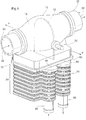
- a heat recovery device 10 according to a first embodiment of the invention is now described with reference to Figures 1 to 9 .
- the heat recovery device 10 may be used as an EGHR device in a motor vehicle exhaust system, and is therefore sometimes referred to herein as EGHR device 10.
- the device 10 comprises a gas diverter valve 12 and a gas/liquid heat exchanger 14.
- the gas diverter valve 12 comprises a valve body 16, a valve element 18 movable between a bypass position shown in Figure 3 and a heat exchange position shown in Figure 4 .
- the valve 12 further comprises a gas inlet 20 and a gas outlet 22 formed in the valve body 16.
- the valve 12 may be constructed of one or more metals able to withstand the high operating temperatures within the exhaust gas stream.
- the valve body 16 may be made from cast iron or steel.
- the valve body may be provided with an internal coolant passage for cooling the valve element 18.
- the device 10 may be mounted within the exhaust gas stream of a motor vehicle, located in-line with the exhaust pipe downstream of the exhaust manifold and upstream of the tailpipe.
- a bypass gas flow path 24 is defined as extending directly from the gas inlet 20 to the gas outlet 22 of valve 12.
- the direction of gas flow within the bypass gas flow path 24 is defined by arrows 26 in Figure 3 .
- the direction of gas flow in the bypass flow path 24 may be the same as the direction of gas flow through the vehicle exhaust system.
- the gas inlet 20 is shown in the drawings as being connected to an upstream exhaust conduit 28 and the gas outlet 22 is shown in the drawings as being connected to a downstream exhaust conduit 30.
- the valve element 18 comprises a flat plate which pivots about a pivot axis P which extends through the valve body at an angle of about 90 degrees to the bypass gas flow path 24.
- the valve element 18 may be mounted on a rod 32, and is rotated in response to temperature of the exhaust gas stream.
- the rotation of valve element 18 may be controlled by any suitable means, including an electronic solenoid or a temperature-responsive wax motor.
- the valve element 18 may be of any suitable shape, including circular or oval, or it may have an irregular shape, being rounded along one end (the right end in Fig. 3 ) to seal with a rounded inside wall of the valve body 16 in the heat exchange mode shown in Figure 4 , and having a flat edge at the opposite end (the left end in Fig. 3 ) to form a seal against the top of the heat exchanger in the heat exchange mode.
- An example of this type of shape is shown in Figure 1 .
- valve element 18 With the valve element 18 in the bypass position illustrated in Figure 3 , the bypass gas flow path 24 is substantially completely open so as to minimize pressure drop of the exhaust gas flowing through valve 12.
- the valve element 18 is not necessarily of the pivoting type, and it will be appreciated that other types of valve elements may be suitable for use in the heat recovery devices according to the invention.
- the heat exchanger 14 is located outside the bypass gas flow path 24 for reasons which will become apparent from the description below.
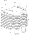
- the heat exchanger 14 comprises a heat exchanger core 34 including a stack of core plates 35.
- the core 34 comprises a plurality of gas flow passages 36 and a plurality of liquid flow passages 38 arranged in alternating order.
- the gas flow passages 36 and the liquid flow passages 38 may be parallel to the bypass gas flow path 24, and are spaced therefrom, and the plates may be horizontally arranged as shown in the drawings, i.e. perpendicular to the vertical plane along which the device 10 is sectioned in Figures 3 and 4 .
- the interiors of the flow passages 36, 38 may be provided with turbulence-enhancing inserts such as ribs or dimples which may be integrally formed as part of plates 35, or such as corrugated fins or turbulizers which are separately formed and inserted into the passages 36, 38.
- turbulence-enhancing inserts such as ribs or dimples which may be integrally formed as part of plates 35, or such as corrugated fins or turbulizers which are separately formed and inserted into the passages 36, 38.
- a plurality of manifolds extend through the core 34, and may be substantially perpendicular to the bypass gas flow path 24, parallel to the vertical plane in which device 10 is sectioned in Figures 3 and 4 .
- Device 10 includes four such manifolds, namely a gas inlet manifold 40 and a gas outlet manifold 42 in flow communication with the gas flow passages 36; and a liquid inlet manifold 44 and a liquid outlet manifold 46 in flow communication with the liquid flow passages 38.
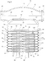
- valve element 18 With the valve element 18 in the bypass position as shown in Figure 3 , flow communication between the gas inlet 20 and the heat exchanger 14 is substantially completely blocked, while the bypass gas flow path 24 is substantially completely open. Therefore, with the valve element 18 in the bypass position, substantially all the exhaust gas flows through the bypass gas flow path 24 between the gas inlet 20 and the gas outlet 22, and there will be little or no flow of exhaust gas through the heat exchanger 14.
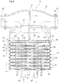
- bypass gas flow path 24 is substantially completely blocked, while flow communication is permitted between the gas inlet 20 and heat exchanger 14, and optionally between the gas outlet 22 and heat exchanger 14.
- the core 34 includes a plurality of core plates 35 which may be identical to one another.
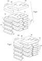
- the two sides of a core plate 35 are illustrated in Figures 6 and 7 , and the relative orientations of a plurality of plates 35 in the core 34 are shown in Figure 5 .
- Figure 6 illustrates the "liquid side” 48 of a core plate 35
- Figure 7 illustrates the opposite "gas side” 50 of the same core plate 35.
- the liquid side 48 denotes the side of plate 35 which defines, in part, one of the liquid flow passages 38
- the gas side 50 denotes the side of plate 35 which defines, in part, one of the gas flow passages 36.
- Each of the core plates 35 has two liquid manifold openings and two gas manifold openings. Specifically, each plate includes a gas inlet manifold opening 52, a gas outlet manifold opening 54, a liquid inlet manifold opening 56 and a liquid outlet manifold opening 58.
- the manifold openings 52, 54, 56 and 58 in plates 35 are aligned in order to form the corresponding manifolds 40, 42, 44 and 46, respectively.
- the liquid inlet and outlet manifold openings 56, 58 are shown as being side-by-side, and the gas inlet and outlet manifold openings 52, 54 are shown as being located at opposite ends of the plates 35. It will be appreciated that the shapes, sizes and arrangement of openings 52, 54, 56, 58 in plates 35 shown in the drawings are dictated by a number of factors which may be specific to particular applications, including packaging requirements, and may be altered without departing from the scope of the present invention.
- the liquid inlet manifold opening 56 and the liquid outlet manifold opening 58 are shown as being recessed relative to a planar base 60 of plate 35, over which the liquid flows through the liquid flow passage 38.
- the liquid inlet manifold opening 56 and the liquid outlet manifold opening 58 of heat exchanger 14, as well as the liquid inlet manifold 44 and liquid outlet manifold 46, are in flow communication with the liquid flow passage 38.
- the gas inlet manifold opening 52 and the gas outlet manifold opening 54 are shown as being raised relative to the planar base 60, and are coplanar with a liquid side sealing surface 62 which includes a central portion surrounding the planar base 60 and liquid manifold openings 56, 58, and two edge portions which completely surround the gas manifold openings 52, 54.
- a liquid side sealing surface 62 which includes a central portion surrounding the planar base 60 and liquid manifold openings 56, 58, and two edge portions which completely surround the gas manifold openings 52, 54.
- the liquid flow passage 38 is U-shaped, with a rib 64 extending part way across the base 60 to prevent short-circuiting of liquid flow between the liquid inlet manifold opening 56 and the liquid outlet manifold opening 58.
- the rib 64 may be co-planar with the liquid side sealing surface 62 so as to contact a rib 64 of an adjacent plate 35 as shown in Figure 3 .
- the rib 64 may be discontinuous as shown in Figure 6 so as to provide good distribution of liquid flow across the planar base 60.
- the rib 64 in Figure 6 includes two portions 65 and 67 of different lengths, with portion 65 being longer than portion 67.
- the gas side 50 of plate 35 is shown in Figure 7 , and has a profile which is the reverse of the liquid side 48.
- the gas flows across a planar base 66, which partially defines the gas flow passage 36, from the gas inlet manifold opening 52 to the gas outlet manifold opening 54.
- the openings 52, 54 are recessed relative to the planar base 66 and therefore the gas inlet and outlet manifold openings 52, 54 and the corresponding gas inlet and outlet manifolds 40, 42 are in flow communication with the gas flow passages 36.
- the gas side 50 of plate 35 has a planar sealing surface 68 which extends about the periphery of gas side 50 for sealing to a sealing surface 68 of an adjacent plate 35 in the core 34.
- liquid inlet and outlet manifold openings 56, 58 on the gas side 50 are raised above the planar base 66 and are coplanar with the sealing surface 68, for sealing to the respective openings 56, 58 in an adjacent plate 35. Therefore, there is no flow communication between the planar base 66 and the liquid manifold openings 56, 58.
- Core plates 35 in the core 34 may be identical in order to reduce manufacturing costs and simplify assembly.
- the core plates at the top and bottom of the core 34 may, however, have different configurations, and are briefly discussed below.
- the top plate 70 of core 34 is defined herein as the core plate which is farthest (distal) from the valve 12, while the bottom plate 72 is defined herein as the core plate which is closest (proximal) to the valve 12.
- the bottom plate 72 has a configuration which differs somewhat from core plates 34.
- the bottom plate 72 includes a gas inlet manifold opening 52 and a gas outlet manifold opening 54 which are co-planar with a base 74.
- the openings 52, 54 and the base 74 are recessed relative to a planar sealing surface 76 of plate 72, and therefore when the bottom plate 72 is sealed to the gas side 50 of an adjacent plate 35 with its sealing surface 76 sealed against the gas side sealing surface 68 of the adjacent core plate 35, a bottom-most gas flow passage 78 is defined at the bottom of core 34, between bottom plate 72 and an adjacent core plate 35.
- the bottom plate may also be formed with a pair of imperforate bosses 80 which are coplanar with the sealing surface 76 of bottom plate 72, and which seal against the liquid inlet and outlet manifold openings 56, 58 of the adjacent core plate 35, thereby closing the bottom of the liquid inlet and outlet manifolds 44, 46.
- the core 34 further includes a top core plate 82 located at the top of core 34.
- the top core plate 82 includes a liquid inlet manifold opening 56 and a liquid outlet manifold opening 58 which are in flow communication with a top-most liquid flow passage 36 formed between the top plate and the liquid side 48 of an adjacent core plate 35.
- the top core plate 82 further includes depressed portions 84 adjacent to its edges which seal against the gas inlet and outlet manifold openings 52, 54 of the adjacent core plate 35, and thereby close the top of the gas inlet and outlet manifolds 40, 42.
- the liquid inlet and outlet manifold openings 56, 58 may be provided with a respective liquid inlet fitting 86 and liquid outlet fitting 88 through which the liquid enters and leaves the heat exchanger 14.
- the valve body 16 has a sealing surface 90 along which the valve body 16 is secured to the heat exchanger 14, and more specifically to the bottom plate 72 of heat exchanger 14.
- the sealing surface 90 surrounds an opening 92 in the valve body 16 through which flow communication is provided between the interior of the valve body 16 and the heat exchanger 14.
- the sealing surface 90 is planar and comprises a flange 94 surrounding the base of the valve body 16.
- the sealing surface 90 may be spaced from the valve element 18 such that a closed chamber 91 is formed inside the valve body 16, between the bypass gas flow path 24 and the sealing surface 90, when the valve element 18 is in the bypass position shown in Figure 3 .
- This closed chamber 91 provides a buffer space between the hot exhaust gas flowing through bypass gas flow path 24 and the relatively cool heat exchanger 14.
- the bottom plate 72 may be directly joined to the sealing surface 90 of valve body 16, for example by brazing or welding.
- a mounting plate 96 is provided inbetween the bottom plate 72 and the sealing surface 90.
- the plate 96 may be secured to the bottom plate 72 by any convenient means, such as by welding, brazing or by means of mechanical fasteners.
- the mounting flange is brazed to the bottom plate 72, and is secured to the valve body 16 by means of mechanical fasteners such as bolts (not shown).
- the peripheral edges of the mounting plate 96 may be provided with a plurality of bolt holes 102.
- valve body 16 and the heat exchanger 14 are made of dissimilar metals which are difficult to braze or weld together.
- the core plates 35 of heat exchanger 14 may be constructed from stainless steel plates, whereas the valve body 16 may be cast iron.
- the mounting plate 96 is also provided with a gas inlet manifold opening 98 and a gas outlet manifold opening 100, the openings 98, 100 being spaced apart from one another in the direction of bypass flow.
- the openings 98, 100 are aligned with the respective gas inlet manifold 40 and gas outlet manifold 42 of the core 34 so as to provide communication between the interior of the valve body 16 and the gas inlet and outlet manifolds 40, 42 of the heat exchanger 14.
- the mounting flange 94 may include a layer of thermally insulating material so as to minimize conduction of heat from the valve body 16 to the heat exchanger 14.
- This thermally insulating layer may take the form of a gasket 95 provided between the mounting plate 96 and the sealing surface 90 of valve body 16.
- the device 10 When used for EGHR, the device 10 transfers heat from the gas to the liquid, the gas being a hot engine exhaust gas, and the liquid being a liquid coolant, for example a water/glycol engine coolant circulating in the vehicle's cooling system.
- EGHR exhaust gas heat recovery
- valve element 18 Upon cold start-up of the vehicle engine, the valve element 18 is actuated so as to adopt the configuration shown in Figure 4 , referred to herein as the heat exchange position or the heat exchange mode. In this position, the valve element 18 substantially completely blocks the bypass gas flow path 24, with the edges of the valve element 18 substantially sealing with the interior walls of the valve body 16 and with a surface of the mounting flange 96. In order to maximize efficiency of EGHR device 10 it is desirable that substantially all of the exhaust gas is diverted from the gas inlet 20 of valve 12 to the gas inlet manifold 40 of heat exchanger 14, and the amount of exhaust gas which leaks past the valve element 18 in the heat exchange position is desirably kept to a minimum, as practicable.
- the exhaust gases are initially relatively cool and gradually warm up to normal operating temperature.
- the heat exchanger 14 and the coolant circulating therein are gradually heated by the exhaust gases. Since the heat exchanger 14 is warmed up gradually, the thermal stresses on the heat exchanger 14 during warm-up are relatively minor.
- the heat exchanger 14 extracts heat from the exhaust gases and transfers it to the liquid coolant. The coolant then flows to other vehicle components, such as a heater core for heating the passenger compartment and for defrosting windows, or to a reservoir for engine or transmission oil, in order to warm and reduce the viscosity of the oil.
- the valve element 18 is actuated so as to bring it to the position shown in Figure 3 , referred to herein as the bypass position or the bypass mode. In this position, the flow through the bypass gas flow path 24 is maximized so as to minimize pressure drop and flow through the heat exchanger 14 is minimized so as to prevent further heat transfer from the exhaust gas to the liquid coolant.
- the amount of exhaust gas which leaks past the valve element 18 in the bypass position and enters heat exchanger 14 is desirably kept to a minimum, as practicable. This minimizes the additional load on the cooling system caused by unwanted heat exchanger between the exhaust gas and the coolant circulating through heat exchanger 14, and also serves to minimize potentially damaging thermal stresses resulting from unnecessary heating of the heat exchanger 14.
- valve element 18 In order to further minimize heat transfer from the exhaust gas to the coolant in the bypass position, it can be seen that the edges of valve element 18 are substantially sealed against an interior surface 97 of the valve body 16, thereby minimizing unwanted gas flow to the heat exchanger 14. Also, the heat exchanger 14 is located outside of the bypass flow path 24 and may be spaced therefrom by chamber 91, which also helps to prevent unwanted heat transfer from the exhaust gas to the coolant. Also, as mentioned above, an insulating gasket 95 is provided between the mounting plate 96 and the valve body 16 so as to minimize heat transfer from valve 12 to heat exchanger 14 via conduction. All of these features are expected to contribute to a reduction in thermal stresses experienced by the heat exchanger 14.
- the bottom-most gas flow passage 36 formed by bottom plate 72 and adjacent core plate 35 does not have liquid flow passages 38 on both sides.
- a further advantage of the device 10 is flexibility. It will be appreciated that the heat exchanger 14 may be sized differently for different applications. Since the heat exchanger 14 is "self-enclosing", i.e. does not include an external housing, and since the plates 35 are stacked horizontally relative to a longitudinal vertical plane through device 10 (i.e. the plane of the cross-sections in Figures 3 and 4 ), the heat exchanger 14 can be made larger or smaller simply by adding or subtracting plates 35 from the core 34, without affecting the configuration of the valve 12. This is advantageous since the same heat exchanger core plates 35 can be used in a variety of different heat exchangers having different heat transfer requirements. For example, differently sized vehicles have passenger compartments of different sizes, and vehicles with larger passenger compartments may have greater heat transfer requirements. All that is needed to adjust the overall heat transfer requirements is to modify the heat exchanger 14 by adding or removing core plates 35.
- a heat recovery device 110 according to a second embodiment of the invention is now described below with reference to Figures 10 and 11 . Most of the elements of device 110 are also included in device 10 and have already been described above, and further description of these elements is unnecessary. The elements which are shared by heat recovery devices 10 and 110 are identified by like reference numerals in the drawings.
- heat recovery device 110 includes a mounting plate 96 at the bottom of heat exchanger 14. As the mounting plate 96 is flat, it will be appreciated that the edge of valve element 18 which seals against the mounting plate 96 will also be flat.
- the mounting plate 96 may be provided with an upstanding flange or tab 104 as shown in Figures 10 and 11 , bent upwardly from the body of the mounting plate 96 so as to provide a more effective lap seal with the valve element 18.
- the tab 104 does not add to the weight of the device 110 since it comprises material which is part of the mounting plate 96.
- the tab 104 may have a rectangular shape, with a long dimension along the extending along the width of the valve element 18.
- the tab 104 may be angled by less than 90 degrees relative to a horizontal axis defined by the direction of the bypass gas flow path 24, more typically from about 45 to less than 90 degrees, and is angled away from a vertical axis in the direction of gas flow.
- the tab 104 overlaps the valve element 18, potentially providing a better seal than in device 10, and also reduces the stroke of the valve element 18 during opening and closing of the bypass gas flow path.
- the tab 104 also eliminates any effect that a variation in the thickness of gasket 95 may have on the seal between valve element 18 and mounting plate 96. In other words, a smaller amount of rotation is required to seal the valve element 18 against tab 104 than is required to seal against the horizontal portion of mounting plate 96.
- the tab 104 also eliminates any effect that a variation in the thickness of gasket 95 may have on the seal between valve element 18 and mounting plate 96.
- the angle of the tab 104 is selected so as to lie flat against the surface of valve element 104 in the heat exchange mode, as shown in Figure 11 . Also, in order to reduce the stroke of the valve element 18, it is desirable that the tab 104 is located toward the gas inlet manifold opening 98 of the mounting plate 96.
- heat recovery devices 10 and 110 can be seen in the shapes of the interior surfaces of the valve body 16 along which the exhaust gases flow into and out of the heat exchanger 14 when the valve element 18 of device 110 is in the heat exchange position, as shown in Figure 11 . It can be seen that the interior surface 97 against which the valve element 18 seals in the bypass position is modified somewhat by providing a rounded inlet surface 106 which still protrudes into the interior of valve body 16, but by a lesser amount than the corresponding portion of surface 97 shown in Figures 3 and 4 . The interior surface 97 is similarly provided with a rounded outlet surface 108 along which the gases flow from the gas outlet manifold 42 of heat exchanger 14 toward the gas outlet 20 of valve 12.
- the rounded outlet surface 108 is gently curved and does not have any inwardly extending protrusion or lip, in contrast to the corresponding portion of surface 97 shown in Figures 3 and 4 .
- the inventors have found that it is particularly important to provide a gently rounded surface between heat exchanger 14 and outlet 20 in order to minimize pressure drop through device 110.
- the surfaces 106, 108 are formed without undue thinning of the walls of valve body 16 so as to avoid weakening, and in Figures 10 and 11 these surfaces are shown as being substantially thicker than other walls of valve body 16. It will be appreciated that the interior and exterior surfaces of the valve body 16 may be contoured so as to provide appropriate wall thicknesses throughout the valve body.
- valve element 18 In order to avoid impairment of the sealing ability of valve element 18 against surface 97, particularly in the bypass mode where leakage of hot gases to the heat exchanger 14 is to be minimized, it may be desired to provide at least one of the surfaces 106, 108 with a small indentation or lip so as to enhance the seal with surface 97 in the bypass mode.
- the rounded outlet surface 108 is provided with such an indentation 112 to enhance the seal with the valve element 108.
Description
- The invention relates to devices for removing heat from gas streams, such as heat recovery devices for removing heat from motor vehicle intake and exhaust gas systems.
- The need to remove heat from gas streams arises in numerous applications. In motor vehicles, for instance, it may be necessary to remove heat from the intake and/or exhaust gas streams. For example, intake air (or "charge air") requires cooling in some applications, for example in turbocharged or supercharged engines. In vehicles incorporating exhaust gas recirculation (EGR) or exhaust gas heat recovery (EGHR) systems, heat is removed from the exhaust gas stream. The heat removed from the intake or exhaust gas stream is typically transferred to a liquid coolant in a heat exchanger.
- In EGHR systems, for example, heat from vehicle exhaust gases is transferred to other vehicle components via a liquid coolant in order to provide faster heating of air and vehicle fluids on start-up of the vehicle, thereby reducing fuel consumption. Air heated by the exhaust gases can be used for rapid heating of the passenger compartment and for window defrosting, reducing the need for long idling periods during start-up in cold weather. Heating of vehicle fluids such as engine oil and transmission fluid makes them less viscous and improves fuel economy during start-up. After the initial start-up period the recovery of heat from the exhaust gases is no longer required. Therefore, EGHR systems typically include a bypass to minimize heat transfer from the exhaust gases to the liquid coolant once the vehicle reaches normal operating temperature. This helps to minimize the load on the cooling system.
- An EGHR system therefore incorporate a gas to liquid heat exchanger for extracting heat from the vehicle exhaust gas and transferring the heat to a liquid coolant, typically a water/glycol engine coolant. The EGHR system also includes a diverter valve for directing at least a portion of the exhaust gas flow through the heat exchanger during vehicle start-up, and for bypassing the heat exchanger once the heat from the exhaust gas is no longer required. An actuator is also provided in order to control operation of the valve. The valve may be operated by means of an electronically controlled solenoid or by a wax motor.
- To save space and to reduce cost and vehicle weight, the valve and heat exchanger may be integrated into a single unit, referred to herein as an EGHR device. In many integrated EGHR devices, however, the heat exchanger is heated by the exhaust gases whether the device is in heat exchange mode or bypass mode. This increases the amount of heat transferred to the coolant, increasing the load on the cooling system, and also producing thermal stresses which can cause damage to the heat exchanger.
- There remains a need for simple and effective EGHR devices for motor vehicle intake and exhaust gas systems which minimize usage of space, weight, and number of components, and which also minimize thermal stresses and unwanted heat transfer to the coolant in bypass mode.
-
US 2008/0184974 discloses an exhaust gas recirculation apparatus including a housing connected with an EGR cooler via a mount face. The housing has a valve chamber accommodating a selector valce and a partition extending from the mount face close to the valve chamber to divide first and second exhaust ports into the EGR cooler and the valve chamber.US 2008/0184974 discloses the preamble ofindependent claim 1. - In an embodiment, there is provided a heat recovery device comprising a gas diverter valve and a gas/liquid heat exchanger. The gas diverter valve comprises a valve body; a valve element movable between a bypass position and a heat exchange position; and a gas inlet and a gas outlet formed in the valve body. The gas/liquid heat exchanger comprises a heat exchanger core comprised of a stack of core plates, the core comprising a plurality of gas flow passages and a plurality of liquid flow passages arranged in alternating order, a gas inlet manifold and a gas outlet manifold in flow communication with said plurality of gas flow passages, and a liquid inlet manifold and a liquid outlet manifold in flow communication with said plurality of liquid flow passages. A bypass gas flow path extends between the gas inlet and the gas outlet of the valve body and the heat exchanger is located outside the bypass gas flow path. With the valve element in the bypass position, the bypass gas flow path is substantially completely open and flow communication between the gas inlet and the heat exchanger is substantially completely blocked by the valve element; and with the valve element in the heat exchange position, the bypass gas flow path is substantially completely blocked by the valve element, and the gas inlet is in flow communication with the heat exchanger.
- The invention will now be described, by way of example only, with reference to the accompanying drawings, in which:
-
Figure 1 is a perspective view of heat recovery device according to a first embodiment of the invention; -
Figure 2 is a perspective view showing the heat exchanger of the heat recovery device ofFigure 1 in isolation; -
Figure 3 is a longitudinal cross-section of the heat recovery device ofFigure 1 in a vertical plane, in bypass mode; -
Figure 4 is a longitudinal cross-section of the heat recovery device ofFigure 1 in a vertical plane, in heat exchange mode; -
Figure 5 are cross-sectional side views through the gas manifold openings of a plurality of heat exchanger plates, the sections being taken along line 5-5 ofFigure 7 ; -
Figure 6 is a perspective view of the coolant side of a core plate in the heat exchanger; -
Figure 7 is a perspective view of the gas side of a core plate in the heat exchanger; -
Figure 8 is a perspective longitudinal cross-section through a portion of the core of the heat exchanger, showing the mounting plate separated from the core; -
Figure 9 is similar toFigure 8 , except that the mounting plate is shown as being attached to the bottom of the core; -
Figure 10 is a longitudinal cross-section of a heat recovery device according to a second embodiment in a vertical plane, in bypass mode; and -
Figure 11 is a longitudinal cross-section of the heat recovery device ofFigure 10 in a vertical plane, in heat exchange mode. - A
heat recovery device 10 according to a first embodiment of the invention is now described with reference toFigures 1 to 9 . Theheat recovery device 10 may be used as an EGHR device in a motor vehicle exhaust system, and is therefore sometimes referred to herein asEGHR device 10. - The
device 10 comprises agas diverter valve 12 and a gas/liquid heat exchanger 14. Thegas diverter valve 12 comprises avalve body 16, avalve element 18 movable between a bypass position shown inFigure 3 and a heat exchange position shown inFigure 4 . Thevalve 12 further comprises agas inlet 20 and agas outlet 22 formed in thevalve body 16. - Where
device 10 is used as an EGHR device, thevalve 12 may be constructed of one or more metals able to withstand the high operating temperatures within the exhaust gas stream. For example, thevalve body 16 may be made from cast iron or steel. Although not necessary, the valve body may be provided with an internal coolant passage for cooling thevalve element 18. - The
device 10 may be mounted within the exhaust gas stream of a motor vehicle, located in-line with the exhaust pipe downstream of the exhaust manifold and upstream of the tailpipe. A bypassgas flow path 24 is defined as extending directly from thegas inlet 20 to thegas outlet 22 ofvalve 12. The direction of gas flow within the bypassgas flow path 24 is defined byarrows 26 inFigure 3 . To minimize pressure drop in the bypass mode, the direction of gas flow in thebypass flow path 24 may be the same as the direction of gas flow through the vehicle exhaust system. Thegas inlet 20 is shown in the drawings as being connected to anupstream exhaust conduit 28 and thegas outlet 22 is shown in the drawings as being connected to adownstream exhaust conduit 30. - As shown in
Figure 1 , thevalve element 18 comprises a flat plate which pivots about a pivot axis P which extends through the valve body at an angle of about 90 degrees to the bypassgas flow path 24. Thevalve element 18 may be mounted on arod 32, and is rotated in response to temperature of the exhaust gas stream. The rotation ofvalve element 18 may be controlled by any suitable means, including an electronic solenoid or a temperature-responsive wax motor. Thevalve element 18 may be of any suitable shape, including circular or oval, or it may have an irregular shape, being rounded along one end (the right end inFig. 3 ) to seal with a rounded inside wall of thevalve body 16 in the heat exchange mode shown inFigure 4 , and having a flat edge at the opposite end (the left end inFig. 3 ) to form a seal against the top of the heat exchanger in the heat exchange mode. An example of this type of shape is shown inFigure 1 . - With the
valve element 18 in the bypass position illustrated inFigure 3 , the bypassgas flow path 24 is substantially completely open so as to minimize pressure drop of the exhaust gas flowing throughvalve 12. Thevalve element 18 is not necessarily of the pivoting type, and it will be appreciated that other types of valve elements may be suitable for use in the heat recovery devices according to the invention. - The
heat exchanger 14 is located outside the bypassgas flow path 24 for reasons which will become apparent from the description below. Theheat exchanger 14 comprises aheat exchanger core 34 including a stack ofcore plates 35. Thecore 34 comprises a plurality ofgas flow passages 36 and a plurality ofliquid flow passages 38 arranged in alternating order. Thegas flow passages 36 and theliquid flow passages 38 may be parallel to the bypassgas flow path 24, and are spaced therefrom, and the plates may be horizontally arranged as shown in the drawings, i.e. perpendicular to the vertical plane along which thedevice 10 is sectioned inFigures 3 and4 . Although not shown in the drawings, the interiors of theflow passages plates 35, or such as corrugated fins or turbulizers which are separately formed and inserted into thepassages - A plurality of manifolds extend through the
core 34, and may be substantially perpendicular to the bypassgas flow path 24, parallel to the vertical plane in whichdevice 10 is sectioned inFigures 3 and4 .Device 10 includes four such manifolds, namely agas inlet manifold 40 and agas outlet manifold 42 in flow communication with thegas flow passages 36; and aliquid inlet manifold 44 and aliquid outlet manifold 46 in flow communication with theliquid flow passages 38. - With the
valve element 18 in the bypass position as shown inFigure 3 , flow communication between thegas inlet 20 and theheat exchanger 14 is substantially completely blocked, while the bypassgas flow path 24 is substantially completely open. Therefore, with thevalve element 18 in the bypass position, substantially all the exhaust gas flows through the bypassgas flow path 24 between thegas inlet 20 and thegas outlet 22, and there will be little or no flow of exhaust gas through theheat exchanger 14. - Conversely, with the
valve element 18 in the heat exchange position as shown inFigure 4 , the bypassgas flow path 24 is substantially completely blocked, while flow communication is permitted between thegas inlet 20 andheat exchanger 14, and optionally between thegas outlet 22 andheat exchanger 14. - As mentioned above, the
core 34 includes a plurality ofcore plates 35 which may be identical to one another. The two sides of acore plate 35 are illustrated inFigures 6 and7 , and the relative orientations of a plurality ofplates 35 in the core 34 are shown inFigure 5 .Figure 6 illustrates the "liquid side" 48 of acore plate 35 andFigure 7 illustrates the opposite "gas side" 50 of thesame core plate 35. Theliquid side 48 denotes the side ofplate 35 which defines, in part, one of theliquid flow passages 38, while thegas side 50 denotes the side ofplate 35 which defines, in part, one of thegas flow passages 36. - Except for the
core plates 35 located at the extreme top and bottom of the core 34, all thecore plates 35 are sealingly joined together in the core 34 with thegas side 50 of eachcore plate 35 facing thegas side 50 of anadjacent core plate 35, and with theliquid side 48 of eachcore plate 35 facing theliquid side 48 of anadjacent core plate 35. This arrangement is illustrated inFigure 5 , showing the relative orientations of threeconsecutive core plates 35 ofheat exchanger 14. - Each of the
core plates 35 has two liquid manifold openings and two gas manifold openings. Specifically, each plate includes a gasinlet manifold opening 52, a gasoutlet manifold opening 54, a liquidinlet manifold opening 56 and a liquidoutlet manifold opening 58. When theplates 35 are stacked to formcore 34, themanifold openings plates 35 are aligned in order to form the correspondingmanifolds - In
plates 35, the liquid inlet andoutlet manifold openings outlet manifold openings plates 35. It will be appreciated that the shapes, sizes and arrangement ofopenings plates 35 shown in the drawings are dictated by a number of factors which may be specific to particular applications, including packaging requirements, and may be altered without departing from the scope of the present invention. - On the
liquid side 48 ofplate 35, the liquidinlet manifold opening 56 and the liquidoutlet manifold opening 58 are shown as being recessed relative to aplanar base 60 ofplate 35, over which the liquid flows through theliquid flow passage 38. As a consequence, the liquidinlet manifold opening 56 and the liquidoutlet manifold opening 58 ofheat exchanger 14, as well as theliquid inlet manifold 44 andliquid outlet manifold 46, are in flow communication with theliquid flow passage 38. Also on theliquid side 48 ofplate 35, the gasinlet manifold opening 52 and the gasoutlet manifold opening 54 are shown as being raised relative to theplanar base 60, and are coplanar with a liquidside sealing surface 62 which includes a central portion surrounding theplanar base 60 and liquidmanifold openings gas manifold openings side sealing surface 62 of oneplate 35 is sealed to the liquidside sealing surface 62 of anadjacent plate 35, there is no flow communication between theplanar base 60 and thegas manifold openings - As shown in
Figure 6 , theliquid flow passage 38 is U-shaped, with arib 64 extending part way across the base 60 to prevent short-circuiting of liquid flow between the liquidinlet manifold opening 56 and the liquidoutlet manifold opening 58. Therib 64 may be co-planar with the liquidside sealing surface 62 so as to contact arib 64 of anadjacent plate 35 as shown inFigure 3 . Therib 64 may be discontinuous as shown inFigure 6 so as to provide good distribution of liquid flow across theplanar base 60. For example, therib 64 inFigure 6 includes twoportions portion 65 being longer thanportion 67. While most of the flow across theplanar base 60 flows around the end ofrib 64, it will be appreciated that a portion of the flow will pass through the gaps to either side ofrib portion 65. While the gaps inrib 64 permit some short-circuiting of flow throughrib 64, the inventors have found that the flow pattern produced by thediscontinuous rib 64 is desirable as it provides a well distributed flow of the liquid across theplanar base 60, thereby enhancing heat transfer. - The
gas side 50 ofplate 35 is shown inFigure 7 , and has a profile which is the reverse of theliquid side 48. In particular, the gas flows across aplanar base 66, which partially defines thegas flow passage 36, from the gasinlet manifold opening 52 to the gasoutlet manifold opening 54. Theopenings planar base 66 and therefore the gas inlet andoutlet manifold openings gas flow passages 36. Thegas side 50 ofplate 35 has aplanar sealing surface 68 which extends about the periphery ofgas side 50 for sealing to a sealingsurface 68 of anadjacent plate 35 in thecore 34. Meanwhile, the liquid inlet andoutlet manifold openings gas side 50 are raised above theplanar base 66 and are coplanar with the sealingsurface 68, for sealing to therespective openings adjacent plate 35. Therefore, there is no flow communication between theplanar base 66 and theliquid manifold openings -
Core plates 35 in the core 34 may be identical in order to reduce manufacturing costs and simplify assembly. The core plates at the top and bottom of the core 34 may, however, have different configurations, and are briefly discussed below. - The
top plate 70 ofcore 34 is defined herein as the core plate which is farthest (distal) from thevalve 12, while thebottom plate 72 is defined herein as the core plate which is closest (proximal) to thevalve 12. - As best seen in the cross-sections of
Figures 3 ,4 and8 , thebottom plate 72 has a configuration which differs somewhat fromcore plates 34. In particular, thebottom plate 72 includes a gasinlet manifold opening 52 and a gasoutlet manifold opening 54 which are co-planar with abase 74. Theopenings planar sealing surface 76 ofplate 72, and therefore when thebottom plate 72 is sealed to thegas side 50 of anadjacent plate 35 with its sealingsurface 76 sealed against the gasside sealing surface 68 of theadjacent core plate 35, a bottom-mostgas flow passage 78 is defined at the bottom ofcore 34, betweenbottom plate 72 and anadjacent core plate 35. The bottom plate may also be formed with a pair ofimperforate bosses 80 which are coplanar with the sealingsurface 76 ofbottom plate 72, and which seal against the liquid inlet andoutlet manifold openings adjacent core plate 35, thereby closing the bottom of the liquid inlet and outlet manifolds 44, 46. - The core 34 further includes a top core plate 82 located at the top of
core 34. The top core plate 82 includes a liquidinlet manifold opening 56 and a liquidoutlet manifold opening 58 which are in flow communication with a top-mostliquid flow passage 36 formed between the top plate and theliquid side 48 of anadjacent core plate 35. The top core plate 82 further includesdepressed portions 84 adjacent to its edges which seal against the gas inlet andoutlet manifold openings adjacent core plate 35, and thereby close the top of the gas inlet and outlet manifolds 40, 42. The liquid inlet andoutlet manifold openings heat exchanger 14. - As shown in
Figures 3 and4 , thevalve body 16 has a sealingsurface 90 along which thevalve body 16 is secured to theheat exchanger 14, and more specifically to thebottom plate 72 ofheat exchanger 14. The sealingsurface 90 surrounds anopening 92 in thevalve body 16 through which flow communication is provided between the interior of thevalve body 16 and theheat exchanger 14. In the illustrated embodiment, the sealingsurface 90 is planar and comprises aflange 94 surrounding the base of thevalve body 16. The sealingsurface 90 may be spaced from thevalve element 18 such that aclosed chamber 91 is formed inside thevalve body 16, between the bypassgas flow path 24 and the sealingsurface 90, when thevalve element 18 is in the bypass position shown inFigure 3 . Thisclosed chamber 91 provides a buffer space between the hot exhaust gas flowing through bypassgas flow path 24 and the relativelycool heat exchanger 14. - The
bottom plate 72 may be directly joined to the sealingsurface 90 ofvalve body 16, for example by brazing or welding. However, in the illustrated embodiment, a mountingplate 96 is provided inbetween thebottom plate 72 and the sealingsurface 90. Theplate 96 may be secured to thebottom plate 72 by any convenient means, such as by welding, brazing or by means of mechanical fasteners. In one embodiment of the invention, the mounting flange is brazed to thebottom plate 72, and is secured to thevalve body 16 by means of mechanical fasteners such as bolts (not shown). For this purpose the peripheral edges of the mountingplate 96 may be provided with a plurality of bolt holes 102. This arrangement may be advantageous where, for example, thevalve body 16 and theheat exchanger 14 are made of dissimilar metals which are difficult to braze or weld together. In this regard, thecore plates 35 ofheat exchanger 14 may be constructed from stainless steel plates, whereas thevalve body 16 may be cast iron. - The mounting
plate 96 is also provided with a gasinlet manifold opening 98 and a gasoutlet manifold opening 100, theopenings openings gas inlet manifold 40 andgas outlet manifold 42 of the core 34 so as to provide communication between the interior of thevalve body 16 and the gas inlet and outlet manifolds 40, 42 of theheat exchanger 14. - The mounting
flange 94 may include a layer of thermally insulating material so as to minimize conduction of heat from thevalve body 16 to theheat exchanger 14. This thermally insulating layer may take the form of agasket 95 provided between the mountingplate 96 and the sealingsurface 90 ofvalve body 16. - The operation and benefits of the
device 10 for exhaust gas heat recovery (EGHR) are now described below. When used for EGHR, thedevice 10 transfers heat from the gas to the liquid, the gas being a hot engine exhaust gas, and the liquid being a liquid coolant, for example a water/glycol engine coolant circulating in the vehicle's cooling system. - Upon cold start-up of the vehicle engine, the
valve element 18 is actuated so as to adopt the configuration shown inFigure 4 , referred to herein as the heat exchange position or the heat exchange mode. In this position, thevalve element 18 substantially completely blocks the bypassgas flow path 24, with the edges of thevalve element 18 substantially sealing with the interior walls of thevalve body 16 and with a surface of the mountingflange 96. In order to maximize efficiency ofEGHR device 10 it is desirable that substantially all of the exhaust gas is diverted from thegas inlet 20 ofvalve 12 to thegas inlet manifold 40 ofheat exchanger 14, and the amount of exhaust gas which leaks past thevalve element 18 in the heat exchange position is desirably kept to a minimum, as practicable. - Upon cold start-up, the exhaust gases are initially relatively cool and gradually warm up to normal operating temperature. During this time, the
heat exchanger 14 and the coolant circulating therein are gradually heated by the exhaust gases. Since theheat exchanger 14 is warmed up gradually, the thermal stresses on theheat exchanger 14 during warm-up are relatively minor. During warm-up, theheat exchanger 14 extracts heat from the exhaust gases and transfers it to the liquid coolant. The coolant then flows to other vehicle components, such as a heater core for heating the passenger compartment and for defrosting windows, or to a reservoir for engine or transmission oil, in order to warm and reduce the viscosity of the oil. - After initial start-up, once the heat from the vehicle exhaust gases is no longer required, the
valve element 18 is actuated so as to bring it to the position shown inFigure 3 , referred to herein as the bypass position or the bypass mode. In this position, the flow through the bypassgas flow path 24 is maximized so as to minimize pressure drop and flow through theheat exchanger 14 is minimized so as to prevent further heat transfer from the exhaust gas to the liquid coolant. In order to maximize efficiency ofEGHR device 10 it is desirable that substantially all of the exhaust gas flows through the bypassgas flow path 24, and that the exhaust gas does not flow through theheat exchanger 14. For example, the amount of exhaust gas which leaks past thevalve element 18 in the bypass position and entersheat exchanger 14 is desirably kept to a minimum, as practicable. This minimizes the additional load on the cooling system caused by unwanted heat exchanger between the exhaust gas and the coolant circulating throughheat exchanger 14, and also serves to minimize potentially damaging thermal stresses resulting from unnecessary heating of theheat exchanger 14. - In order to further minimize heat transfer from the exhaust gas to the coolant in the bypass position, it can be seen that the edges of
valve element 18 are substantially sealed against aninterior surface 97 of thevalve body 16, thereby minimizing unwanted gas flow to theheat exchanger 14. Also, theheat exchanger 14 is located outside of thebypass flow path 24 and may be spaced therefrom bychamber 91, which also helps to prevent unwanted heat transfer from the exhaust gas to the coolant. Also, as mentioned above, an insulatinggasket 95 is provided between the mountingplate 96 and thevalve body 16 so as to minimize heat transfer fromvalve 12 toheat exchanger 14 via conduction. All of these features are expected to contribute to a reduction in thermal stresses experienced by theheat exchanger 14. - Also, in contrast to the other
gas flow passages 36 incore 34, the bottom-mostgas flow passage 36 formed bybottom plate 72 andadjacent core plate 35 does not haveliquid flow passages 38 on both sides. In particular, there is noliquid flow passage 38 between the bottom-mostgas flow passage 36 and the mountingflange 96. This helps to further minimize thermal stresses which could result if the coolant in aliquid flow passage 38 located at the bottom of theheat exchanger 14 were in contact with the mountingplate 96. - A further advantage of the
device 10 is flexibility. It will be appreciated that theheat exchanger 14 may be sized differently for different applications. Since theheat exchanger 14 is "self-enclosing", i.e. does not include an external housing, and since theplates 35 are stacked horizontally relative to a longitudinal vertical plane through device 10 (i.e. the plane of the cross-sections inFigures 3 and4 ), theheat exchanger 14 can be made larger or smaller simply by adding or subtractingplates 35 from thecore 34, without affecting the configuration of thevalve 12. This is advantageous since the same heatexchanger core plates 35 can be used in a variety of different heat exchangers having different heat transfer requirements. For example, differently sized vehicles have passenger compartments of different sizes, and vehicles with larger passenger compartments may have greater heat transfer requirements. All that is needed to adjust the overall heat transfer requirements is to modify theheat exchanger 14 by adding or removingcore plates 35. - A
heat recovery device 110 according to a second embodiment of the invention is now described below with reference toFigures 10 and11 . Most of the elements ofdevice 110 are also included indevice 10 and have already been described above, and further description of these elements is unnecessary. The elements which are shared byheat recovery devices - As mentioned above, the leakage of exhaust gas past the
valve element 18 is desirably minimized in the heat exchange position. In this position, one edge of thevalve element 18 must seal against theheat exchanger 14, more specifically against the bottom of theheat exchanger 14, or against the mountingplate 96 where one is used. In the present embodiment,heat recovery device 110 includes a mountingplate 96 at the bottom ofheat exchanger 14. As the mountingplate 96 is flat, it will be appreciated that the edge ofvalve element 18 which seals against the mountingplate 96 will also be flat. - In order to improve sealing of the
valve element 18, the mountingplate 96 may be provided with an upstanding flange ortab 104 as shown inFigures 10 and11 , bent upwardly from the body of the mountingplate 96 so as to provide a more effective lap seal with thevalve element 18. Thetab 104 does not add to the weight of thedevice 110 since it comprises material which is part of the mountingplate 96. Thetab 104 may have a rectangular shape, with a long dimension along the extending along the width of thevalve element 18. Thetab 104 may be angled by less than 90 degrees relative to a horizontal axis defined by the direction of the bypassgas flow path 24, more typically from about 45 to less than 90 degrees, and is angled away from a vertical axis in the direction of gas flow. It can be seen by comparing the heat exchange position of device 110 (Figure 11 ) with the heat exchange mode of device 10 (Figure 4 ), that thetab 104 overlaps thevalve element 18, potentially providing a better seal than indevice 10, and also reduces the stroke of thevalve element 18 during opening and closing of the bypass gas flow path. Thetab 104 also eliminates any effect that a variation in the thickness ofgasket 95 may have on the seal betweenvalve element 18 and mountingplate 96. In other words, a smaller amount of rotation is required to seal thevalve element 18 againsttab 104 than is required to seal against the horizontal portion of mountingplate 96. Thetab 104 also eliminates any effect that a variation in the thickness ofgasket 95 may have on the seal betweenvalve element 18 and mountingplate 96. The angle of thetab 104 is selected so as to lie flat against the surface ofvalve element 104 in the heat exchange mode, as shown inFigure 11 . Also, in order to reduce the stroke of thevalve element 18, it is desirable that thetab 104 is located toward the gasinlet manifold opening 98 of the mountingplate 96. - Another difference between
heat recovery devices valve body 16 along which the exhaust gases flow into and out of theheat exchanger 14 when thevalve element 18 ofdevice 110 is in the heat exchange position, as shown inFigure 11 . It can be seen that theinterior surface 97 against which thevalve element 18 seals in the bypass position is modified somewhat by providing arounded inlet surface 106 which still protrudes into the interior ofvalve body 16, but by a lesser amount than the corresponding portion ofsurface 97 shown inFigures 3 and4 . Theinterior surface 97 is similarly provided with arounded outlet surface 108 along which the gases flow from thegas outlet manifold 42 ofheat exchanger 14 toward thegas outlet 20 ofvalve 12. In particular, therounded outlet surface 108 is gently curved and does not have any inwardly extending protrusion or lip, in contrast to the corresponding portion ofsurface 97 shown inFigures 3 and4 . The inventors have found that it is particularly important to provide a gently rounded surface betweenheat exchanger 14 andoutlet 20 in order to minimize pressure drop throughdevice 110. - The
surfaces valve body 16 so as to avoid weakening, and inFigures 10 and11 these surfaces are shown as being substantially thicker than other walls ofvalve body 16. It will be appreciated that the interior and exterior surfaces of thevalve body 16 may be contoured so as to provide appropriate wall thicknesses throughout the valve body. - In order to avoid impairment of the sealing ability of
valve element 18 againstsurface 97, particularly in the bypass mode where leakage of hot gases to theheat exchanger 14 is to be minimized, it may be desired to provide at least one of thesurfaces surface 97 in the bypass mode. InFigures 10 and11 the roundedoutlet surface 108 is provided with such anindentation 112 to enhance the seal with thevalve element 108. - Although the invention has been described in connection with certain preferred embodiments, it is not limited thereto.
Claims (12)
- A heat recovery device (10) comprising a gas diverter valve (12) and a gas/liquid heat exchanger (14);
the gas diverter valve (12) comprising a valve body (16); a valve element (18) movable between a bypass position and a heat exchange position; and a gas inlet (20) and a gas outlet (22) formed in the valve body (16);
wherein a bypass gas flow path (24) extends between the gas inlet (20) and the gas outlet (22) of the valve body (16) and the heat exchanger (14) is located outside the bypass gas flow path (24);
wherein, with the valve element (18) in the bypass position, the bypass gas flow path (24) is substantially completely open and flow communication between the gas inlet (20) and the heat exchanger (14) is substantially completely blocked by the valve element (18); and
with the valve element (18) in the heat exchange position, the bypass gas flow path (24) is substantially completely blocked by the valve element (18), and the gas inlet (20) is in flow communication with the heat exchanger (14);
characterized in that:the gas/liquid heat exchanger (14) comprises a heat exchanger core (34) comprised of a stack of core plates (35), the core (34) comprising a plurality of gas flow passages (36) and a plurality of liquid flow passages (38) arranged in alternating order, a gas inlet manifold (40) and a gas outlet manifold (42) in flow communication with said plurality of gas flow passages (36), and a liquid inlet manifold (44) and a liquid outlet manifold (46) in flow communication with said plurality of liquid flow passages (38);in that each of the core plates (35) has a gas side (50) and a liquid side (48), and wherein the core plates (35) are sealed together in the core (34) such that each of the gas flow passages (36) is defined between the gas sides (50) of two adjacent core plates and each of the liquid flow passages (38) is defined between the liquid sides (48) of two adjacent core plates, and such that the manifold openings in the plates align to form said manifolds, with the gas inlet (40) and outlet (42) manifolds in flow communication with the gas flow passages (36) and the liquid inlet (44) and outlet (46) manifolds in flow communication with the liquid flow passages (38);
wherein a bottom of said core (34) is proximate to the valve body (16) and a top of said core (34) is distal to the valve body (16), and wherein the core (34) includes a bottom core plate (72) located at the bottom of the core (34);wherein the bottom core plate (72) includes one of said gas inlet manifold openings (52) and one of said gas outlet manifold openings (54);wherein a bottom-most gas flow passage (78) is defined between the bottom plate (72) and an adjacent one of said core plates (35);wherein said bottom-most gas flow passage (78) is in direct heat exchange contact with only one of said liquid flow passages (38); andwherein the bottom plate (72) forms a closed bottom of the liquid inlet manifold (44) and a closed bottom of the liquid outlet manifold (46). - The heat recovery device (10) according to claim 1, wherein a bottom of said core (34) is proximate to the valve body (16) and a top of said core (34) is distal to the valve body (16), and wherein the core (34) includes a top core plate (82) located at the top of the core (34);
wherein the top core plate (82) includes a liquid inlet manifold opening (56) and a liquid outlet manifold opening (58) and forms a closed top of the gas inlet manifold (40) and a closed top of the gas outlet manifold (42); and
wherein the liquid inlet manifold opening (56) of the top core plate (82) is provided with a liquid inlet fitting (86) and the liquid outlet manifold opening (58) of the top core plate (82) is provided with a liquid outlet fitting (88). - The heat recovery device (10) according to any one of claims 1 to 2, further comprising a mounting plate (96) secured to the bottom plate (72) of the heat exchanger (14);
wherein the valve body (16) has a sealing surface (90) along which it is secured to the mounting plate (96), said sealing surface (90) surrounding an opening (92) in said valve body (16) through which flow communication is provided between an interior of the valve body (16) and the heat exchanger (14);
wherein a thermally insulating gasket (95) is optionally provided between the sealing surface (90) of the valve body (16) and the mounting plate (96); and/or
wherein the valve body (16) is optionally secured to the mounting plate (96) by mechanical fasteners. - The heat recovery device (10) according to claim 3, wherein the mounting plate (96) is provided with a gas inlet manifold opening (98) in alignment with said gas inlet manifold (40) and a gas outlet manifold opening (100) in alignment with said gas outlet manifold (42), and wherein the gas inlet (40) and outlet (42) manifold openings of the mounting plate (96) are spaced apart from one another along the bypass gas flow path (24).
- The heat recovery device (10) according to claim 4, wherein the sealing surface (90) of the valve body (16), the mounting plate (96), and a sealing surface of the bottom plate (72) are planar; and
wherein the sealing surface of the bottom plate (72) surrounds the gas inlet (40) and outlet (42) manifolds of the bottom plate (72). - The heat recovery device (10) according to claim 5, wherein the valve element (18) pivots along a pivot axis (P) extending through the valve body (16) at an angle of about 90 degrees to the bypass gas flow path (24), and wherein an edge of the valve element (18) engages a surface of the mounting plate (96) with the valve element (18) in the heat exchange position.
- The heat recovery device (10) according to claim 6, said surface of the mounting plate (96) is provided with an upstanding flange which engages and overlaps an edge of the valve element (18) when the valve element (18) is in the heat exchange position.
- The heat recovery device (10) according to any one of claims 1 to 7, wherein the liquid inlet manifold opening (56) and the liquid outlet manifold opening (58) are provided along one side of the core plate (35), wherein the liquid flow passages (38) are U-shaped, and wherein a rib (64) separates the liquid inlet (44) and outlet (46) manifold openings to prevent short-circuiting flow between the manifold openings; and wherein the rib (64) is discontinuous, and provides gaps through which a portion of the liquid is able to flow through the rib (64).
- The heat recovery device (10) according to any one of claims 1 to 8, wherein surfaces of the valve body (16) extending between the gas inlet and the heat exchanger (14), and between the heat exchanger (14) and the gas outlet, are smoothly rounded; and
wherein said valve element (18) optionally engages said smoothly rounded surfaces with the valve element (18) in the bypass position. - The heat recovery device (10) according to claim 9, wherein at least one of said smoothly rounded surfaces is provided with an indentation to receive an edge of the valve element (18) when the valve element (18) is in the bypass position.
- The heat recovery device (10) according to any one of claims 1 to 10, wherein the heat transfer requirements of the device are adjustable by adding or removing one or more of said identical core plates (35) to or from the core (34) of the heat exchanger (14).
- The heat recovery device (10) according to any one of claims 1 to 11, wherein the valve body (16) has a sealing surface (90) along which it is secured to the heat exchanger (14), said sealing surface (90) surrounding an opening (92) in said valve body (16) through which flow communication is provided between an interior of the valve body (16) and the heat exchanger (14); and
with the valve element (18) in the bypass position, the sealing surface (92) of the valve body (16) is spaced from the valve element (18) such that a closed chamber (91) is formed inside the valve body (16) between the bypass gas flow path (24) and the sealing surface (90).
Applications Claiming Priority (2)
| Application Number | Priority Date | Filing Date | Title |
|---|---|---|---|
| US201161532677P | 2011-09-09 | 2011-09-09 | |
| PCT/CA2012/050598 WO2013033839A1 (en) | 2011-09-09 | 2012-08-30 | Stacked plate exhaust gas recovery device |
Publications (3)
| Publication Number | Publication Date |
|---|---|
| EP2766687A1 EP2766687A1 (en) | 2014-08-20 |
| EP2766687A4 EP2766687A4 (en) | 2015-09-23 |
| EP2766687B1 true EP2766687B1 (en) | 2019-04-24 |
Family
ID=47828601
Family Applications (1)
| Application Number | Title | Priority Date | Filing Date |
|---|---|---|---|
| EP12829797.5A Not-in-force EP2766687B1 (en) | 2011-09-09 | 2012-08-30 | Stacked plate exhaust gas recovery device |
Country Status (7)
| Country | Link |
|---|---|
| US (1) | US9121316B2 (en) |
| EP (1) | EP2766687B1 (en) |
| JP (1) | JP6556451B2 (en) |
| KR (1) | KR20140075710A (en) |
| CN (1) | CN103906987B (en) |
| CA (1) | CA2846284A1 (en) |
| WO (1) | WO2013033839A1 (en) |
Families Citing this family (39)
| Publication number | Priority date | Publication date | Assignee | Title |
|---|---|---|---|---|
| EP2413045B1 (en) * | 2010-07-30 | 2014-02-26 | Grundfos Management A/S | Heat exchange unit |
| FR2990740B1 (en) * | 2012-05-15 | 2014-05-02 | Valeo Sys Controle Moteur Sas | FLUID CIRCULATION VALVE, IN PARTICULAR FOR A MOTOR VEHICLE, AND THERMAL CONDITIONING DEVICE COMPRISING SUCH A VALVE |
| US10207567B2 (en) * | 2012-10-19 | 2019-02-19 | Ford Global Technologies, Llc | Heater core isolation valve position detection |
| DE112014000953T5 (en) | 2013-02-22 | 2015-11-05 | Dana Canada Corporation | Heat exchanger device with distributor cooling |
| US9989322B2 (en) * | 2013-03-01 | 2018-06-05 | Dana Canada Corporation | Heat recovery device with improved lightweight flow coupling chamber and insertable valve |
| US20140251579A1 (en) * | 2013-03-05 | 2014-09-11 | Wescast Industries, Inc. | Heat recovery system and heat exchanger |
| EP2781730A1 (en) * | 2013-03-19 | 2014-09-24 | Borgwarner Inc. | Compact device for exhaust gas management in an EGR system |
| WO2015038111A1 (en) * | 2013-09-11 | 2015-03-19 | International Engine Intellectual Property Company, Llc | Thermal screen for an egr cooler |
| US20150167519A1 (en) * | 2013-12-16 | 2015-06-18 | Dana Canada Corporation | Heat recovery device with standoff heat exchanger mount |
| KR101610099B1 (en) * | 2014-04-30 | 2016-04-08 | 현대자동차 주식회사 | Heat exchanger of can type |
| US10295282B2 (en) | 2014-07-21 | 2019-05-21 | Dana Canada Corporation | Heat exchanger with flow obstructions to reduce fluid dead zones |
| DE102014110616A1 (en) | 2014-07-28 | 2016-01-28 | Tenneco Gmbh | Valve housing with valve flap |
| KR102228203B1 (en) * | 2014-07-31 | 2021-03-17 | 한온시스템 주식회사 | Oil Cooler |
| KR101977824B1 (en) * | 2015-03-04 | 2019-05-13 | 상고 컴패니, 리미티드 | Heat exchanger, and exhaust heat recovery device provided with said heat exchanger |
| EP3124907B1 (en) * | 2015-07-29 | 2019-04-10 | Zhejiang Sanhua Automotive Components Co., Ltd. | Heat exchange device |
| EP3141715B1 (en) | 2015-09-14 | 2018-07-11 | Bosal Emission Control Systems NV | Heat recovery component for an exhaust gas system of an internal combustion engine |
| US10408333B2 (en) | 2015-12-09 | 2019-09-10 | Ford Global Technologies, Llc | Rear axle lubrication oil temperature control using exhaust heat recovery and a thermal battery |
| CN105484823A (en) * | 2015-12-14 | 2016-04-13 | 黄相之 | Emission reduction and oil saving device for engine |
| EP3203173B1 (en) * | 2016-02-03 | 2018-12-26 | Mahle International GmbH | Exhaust gas heat exchanger |
| GB2549123B (en) * | 2016-04-06 | 2019-10-09 | Jaguar Land Rover Ltd | Energy recovery unit for vehicle use |
| DE102017205434A1 (en) | 2016-04-11 | 2017-10-26 | Toyota Jidosha Kabushiki Kaisha | Exhaust heat recovery device |
| JP6608857B2 (en) * | 2016-04-11 | 2019-11-20 | トヨタ自動車株式会社 | Waste heat recovery device |
| DE102016210684A1 (en) | 2016-06-15 | 2017-12-21 | Hanon Systems | exhaust valve |
| US11137212B2 (en) | 2016-06-23 | 2021-10-05 | Hanon Systems | Bypass seal for plate heater matrix |
| KR101679743B1 (en) * | 2016-06-28 | 2016-12-02 | (주)시에스 | Heat exchanger for exhaust heat recovery system of vehicle |
| EP3591199A1 (en) | 2016-11-08 | 2020-01-08 | C.R.F. Società Consortile per Azioni | A unit for conversion of thermal energy |
| CN108068572B (en) * | 2016-11-09 | 2022-08-05 | 杭州三花研究院有限公司 | Fluid heat exchange assembly and vehicle thermal management system |
| US11285781B2 (en) | 2016-11-09 | 2022-03-29 | Zhejiang Sanhua Intelligent Controls Co., Ltd | Fluid heat exchange assembly, and heat management system of vehicle |
| JP6809300B2 (en) * | 2017-03-06 | 2021-01-06 | 株式会社デンソー | Exhaust recirculation device |
| GB2560352B (en) * | 2017-03-09 | 2020-05-27 | Perkins Engines Co Ltd | Aftertreatment canister mounting bracket |
| KR102299349B1 (en) * | 2017-04-10 | 2021-09-08 | 현대자동차주식회사 | Egr cooler for vehicle |
| US10865700B2 (en) | 2017-07-10 | 2020-12-15 | Bombardier Recreational Products Inc. | Air intake and exhaust systems for a snowmobile engine |
| CN108561214B (en) * | 2018-01-10 | 2020-03-20 | 吕衍荣 | Engine tail gas treatment system and method thereof |
| CN108116294A (en) * | 2018-02-02 | 2018-06-05 | 李崇楷 | It is a kind of to utilize the plug-in water tank of car engine exhaust pipe heated type |
| KR102542945B1 (en) * | 2018-04-24 | 2023-06-15 | 현대자동차주식회사 | Heat exchanger for vehicles |
| CA3101940A1 (en) * | 2018-05-31 | 2019-12-05 | Bombardier Recreational Products Inc. | Exhaust system for an engine |
| JP7129744B2 (en) * | 2018-08-06 | 2022-09-02 | 三恵技研工業株式会社 | Exhaust heat recovery equipment for automobiles |
| CN109555623B (en) * | 2018-10-17 | 2023-04-28 | 天津大学 | Intelligent engine cold start device for heating air intake by exhaust gas and control method |
| DE202018004979U1 (en) * | 2018-10-25 | 2020-01-28 | Reinz-Dichtungs-Gmbh | Plate-like liquid container and battery temperature control arrangement |
Family Cites Families (103)
| Publication number | Priority date | Publication date | Assignee | Title |
|---|---|---|---|---|
| GB192489A (en) | 1921-11-02 | 1923-02-02 | Elbridge Christmond Collins | Improvements in power generating apparatus |
| US1810286A (en) | 1927-04-06 | 1931-06-16 | Macphee Anderson | Heat exchanger |
| US2268979A (en) | 1940-04-05 | 1942-01-06 | Maxim Silencer Co | Exhaust gas heater |
| US3050935A (en) | 1961-01-05 | 1962-08-28 | Socony Mobil Oil Co Inc | Apparatus for catalytically treating internal combustion engine exhaust gases |
| AT299724B (en) | 1968-07-29 | 1972-06-26 | Eberspaecher J | Heat exchangers, preferably for vehicle heating |
| GB1300948A (en) | 1969-10-07 | 1972-12-29 | Rolls Royce | Improvements in or relating to power plants |
| GB1467255A (en) | 1973-04-19 | 1977-03-16 | Shell Int Research | Internal combustion engines comprising fuel vapourising devices |
| JPS5517230B2 (en) | 1973-07-30 | 1980-05-09 | ||
| DE3103199A1 (en) | 1981-01-30 | 1982-08-26 | Oskar Dr.-Ing. 8031 Stockdorf Schatz | METHOD FOR OPERATING A HEAT EXCHANGER WITH THE EXHAUST GASES OF A PISTON ENGINE, IN PARTICULAR FOR HEATING A MOTOR VEHICLE, AND HEAT EXCHANGER ARRANGEMENT FOR CARRYING OUT THE METHOD |
| US4391235A (en) | 1981-05-28 | 1983-07-05 | Majkrzak David S | Vehicle exhaust gas warm-up heater system |
| EP0197823A1 (en) | 1985-03-20 | 1986-10-15 | Valeo | Heat exchanger for a motor vehicle, particularly of the type for exhaust gases |
| JPH0668439B2 (en) * | 1986-07-11 | 1994-08-31 | 日本電装株式会社 | Stacked heat exchanger |
| JPH0674870U (en) * | 1993-02-25 | 1994-10-21 | 岩井機械工業株式会社 | Plate heat exchanger |
| JPH07269332A (en) | 1994-03-29 | 1995-10-17 | Ngk Insulators Ltd | Exhaust emission control device and butterfly valve therefor |
| FR2755727B1 (en) | 1996-11-08 | 1999-01-15 | Valeo Thermique Moteur Sa | CATALYST CONTAINER WITH PROTECTION OF THE CATALYST AGAINST HIGH TEMPERATURES |
| US6164553A (en) | 1997-07-07 | 2000-12-26 | Derksen; William Edmond | Heat recovery system and heat exchanger therefor |
| FR2770582B1 (en) | 1997-10-31 | 2000-01-28 | Valeo Thermique Moteur Sa | GAS EXHAUST AND RECIRCULATION LINE FOR MOTOR VEHICLE ENGINES |
| FR2776015B1 (en) | 1998-03-11 | 2000-08-11 | Ecia Equip Composants Ind Auto | HEAT EXCHANGER EXHAUST MEMBER |
| DE19833338A1 (en) | 1998-07-24 | 2000-01-27 | Modine Mfg Co | Heat exchangers, in particular exhaust gas heat exchangers |
| DE19846518B4 (en) | 1998-10-09 | 2007-09-20 | Modine Manufacturing Co., Racine | Heat exchangers, in particular for gases and liquids |
| SE521713C2 (en) | 1998-11-09 | 2003-12-02 | Stt Emtec Ab | Procedure and apparatus for an EGR system, and such valve |
| US6244256B1 (en) | 1999-10-07 | 2001-06-12 | Behr Gmbh & Co. | High-temperature coolant loop for cooled exhaust gas recirculation for internal combustion engines |
| EP1242760A4 (en) | 1999-12-29 | 2005-03-23 | Visteon Global Tech Inc | Exhaust valve for combustion engines |
| GB0001283D0 (en) | 2000-01-21 | 2000-03-08 | Serck Heat Transfer Limited | Twin flow valve gas cooler |
| DE10011954A1 (en) | 2000-03-11 | 2001-09-13 | Modine Mfg Co | Exhaust gas heat exchanger in an exhaust gas recirculation arrangement |
| GB0115126D0 (en) | 2001-06-21 | 2001-08-15 | Invectoment Ltd | High temperature damper |
| DE10144293A1 (en) | 2001-08-31 | 2003-04-03 | Siemens Ag | Valve component set for internal bypass flow |
| DE10153383A1 (en) | 2001-10-30 | 2003-05-22 | Visteon Global Tech Inc | Exhaust heat recovery device |
| DE10203003B4 (en) | 2002-01-26 | 2007-03-15 | Behr Gmbh & Co. Kg | Exhaust gas heat exchanger |
| DE10214467A1 (en) | 2002-03-30 | 2003-10-09 | Modine Mfg Co | Exhaust gas heat exchanger for motor vehicles |
| DE10216537B3 (en) | 2002-04-15 | 2004-02-05 | Visteon Global Technologies, Inc., Dearborn | Reversing device for flowing media, in particular switch valve for the exhaust gases of an internal combustion engine |
| ATE431498T1 (en) | 2002-05-15 | 2009-05-15 | Behr Gmbh & Co Kg | SWITCHABLE EXHAUST GAS HEAT EXCHANGER |
| US7159650B2 (en) | 2002-06-28 | 2007-01-09 | Modine Manufacturing Company | Heat exchanger |
| DE10232515A1 (en) | 2002-07-18 | 2004-04-08 | Daimlerchrysler Ag | Exhaust gas recirculation of an internal combustion engine |
| DE10260251A1 (en) | 2002-12-20 | 2004-07-01 | Siemens Ag | Cooling element for gases |
| DE10303910A1 (en) | 2003-01-31 | 2004-08-12 | Arvin Technologies Inc., Columbus | Assembly consisting of exhaust gas heat exchanger and bypass |
| DE20302520U1 (en) | 2003-02-17 | 2004-06-24 | Arvin Technologies Inc., Columbus | Valve for an exhaust pipe |
| FR2854103B1 (en) | 2003-04-24 | 2006-06-02 | Peugeot Citroen Automobiles Sa | METHOD AND DEVICE FOR HEATING A VEHICLE OF A MOTOR VEHICLE |
| FR2854200B1 (en) | 2003-04-25 | 2007-06-29 | Faurecia Sys Echappement | EXHAUST FOR INTERNAL COMBUSTION ENGINE |
| US7100369B2 (en) | 2003-05-06 | 2006-09-05 | Denso Corporation | Thermoelectric generating device |
| DE10327481A1 (en) | 2003-06-18 | 2005-01-05 | Modine Manufacturing Co., Racine | Casing-free plate heat exchanger with collecting box |
| DE10328638A1 (en) | 2003-06-26 | 2005-01-20 | Modine Manufacturing Co., Racine | Heat exchanger in caseless plate design |
| FR2859239B1 (en) | 2003-08-29 | 2006-01-20 | Valeo Thermique Moteur Sa | THERMAL CONTROL DEVICE FOR EXHAUST GAS |
| FR2859238B1 (en) | 2003-08-29 | 2006-01-20 | Valeo Thermique Moteur Sa | THERMAL CONTROL DEVICE FOR EXHAUST GAS |
| US7353865B2 (en) | 2003-09-05 | 2008-04-08 | Arvinmeritor Technology, Llc | Method for controlling a valve for an exhaust system |
| US7108054B2 (en) * | 2003-09-11 | 2006-09-19 | Honeywell International, Inc. | Heat exchanger |
| FR2864582B1 (en) * | 2003-12-24 | 2006-03-17 | Valeo Thermique Moteur Sa | HEAT EXCHANGE MODULE FOR CONTROLLING THE TEMPERATURE OF GASES ADMITTED IN A MOTOR VEHICLE THERMAL MOTOR |
| DE102004018197A1 (en) | 2004-04-15 | 2005-11-03 | Modine Manufacturing Co., Racine | Exhaust gas heat exchanger |
| DE102004019554C5 (en) | 2004-04-22 | 2014-03-27 | Pierburg Gmbh | Exhaust gas recirculation system for an internal combustion engine |
| DE502004002379D1 (en) | 2004-08-14 | 2007-02-01 | Modine Mfg Co | Heat exchanger, consisting of flat tubes |
| DE502004003357D1 (en) | 2004-11-10 | 2007-05-10 | Modine Mfg Co | Heat exchanger with open profile as housing |
| JP4457869B2 (en) | 2004-11-25 | 2010-04-28 | トヨタ自動車株式会社 | Abnormality detection device for exhaust heat recovery system |
| GB2420593B (en) | 2004-11-29 | 2007-04-25 | Gibbs Tech Ltd | An exhaust cooling system of an amphibious vehicle |
| US7198037B2 (en) * | 2004-12-14 | 2007-04-03 | Honeywell International, Inc. | Bypass for exhaust gas cooler |
| US7056173B1 (en) | 2004-12-21 | 2006-06-06 | Heater Craft Marine Products | Heater and a method for delivering heat energy from a water cooled two cycle marine engine |
| US20060174611A1 (en) | 2005-02-07 | 2006-08-10 | Dilley Roland L | Exhaust gas cooler |
| WO2006090725A1 (en) | 2005-02-23 | 2006-08-31 | Sango Co., Ltd. | Exhaust heat recovery device |
| JP4551272B2 (en) * | 2005-05-06 | 2010-09-22 | 株式会社三五 | Exhaust heat recovery device |
| JP4341593B2 (en) | 2005-06-29 | 2009-10-07 | トヨタ自動車株式会社 | Waste heat recovery device |
| ES2300163B1 (en) | 2005-07-29 | 2009-05-01 | Valeo Termico, S.A. | SYSTEM FOR THE CONTROL OF GAS CIRCULATION, IN SPECIAL OF THE EXHAUST GASES OF A MOTOR. |
| DE102005040612A1 (en) * | 2005-08-27 | 2007-03-01 | Behr Gmbh & Co. Kg | Exhaust gas heat exchanger for exhaust gas recirculation system of internal combustion system, has bypass pipe, designed as high-grade steel pipe having jacket made of high temperature stable plastic, arranged in coolant flowing housing |
| ES2279713B1 (en) * | 2005-12-23 | 2008-06-16 | Valeo Termico, S.A. | HEAT EXCHANGER OF STACKED PLATES. |
| DE102006005362A1 (en) | 2006-02-07 | 2007-08-09 | Modine Manufacturing Co., Racine | Exhaust gas heat exchanger in an exhaust gas recirculation arrangement |
| EP1999423B1 (en) | 2006-03-16 | 2015-06-03 | MAHLE Behr GmbH & Co. KG | Exhaust gas cooler for a motor vehicle |
| EP2002093B1 (en) | 2006-03-16 | 2011-09-14 | Toyota Jidosha Kabushiki Kaisha | Exhaust gas heat recovery device |
| US7380544B2 (en) | 2006-05-19 | 2008-06-03 | Modine Manufacturing Company | EGR cooler with dual coolant loop |
| DE102006028578B4 (en) | 2006-06-22 | 2020-03-12 | Modine Manufacturing Co. | Heat exchangers, in particular exhaust gas heat exchangers |
| KR101298382B1 (en) | 2006-07-03 | 2013-08-20 | 모다인 매뉴팩츄어링 컴파니 | Egr cooler |
| JP5220008B2 (en) | 2006-07-14 | 2013-06-26 | ベール ゲーエムベーハー ウント コー カーゲー | Device for cooling the gas flow of an internal combustion engine |
| GB2441588B (en) | 2006-09-06 | 2011-02-23 | Gt Group Ltd | Improved butterfly valve |
| US7610949B2 (en) * | 2006-11-13 | 2009-11-03 | Dana Canada Corporation | Heat exchanger with bypass |
| US20080141985A1 (en) * | 2006-12-18 | 2008-06-19 | Schernecker Jeff L | Layered core EGR cooler |
| JP2008215336A (en) * | 2007-02-05 | 2008-09-18 | Denso Corp | Exhaust gas recirculation apparatus |
| US7958874B2 (en) * | 2007-02-05 | 2011-06-14 | Denso Corporation | Exhaust gas recirculation apparatus |
| GB2444792B (en) | 2007-03-17 | 2008-11-12 | Senior Uk Ltd | U-shaped cooler |
| JP2009002239A (en) * | 2007-06-21 | 2009-01-08 | T Rad Co Ltd | Egr cooler |
| JP2009008318A (en) * | 2007-06-27 | 2009-01-15 | Denso Corp | Exhaust heat recovery device |
| DE102007038882A1 (en) | 2007-08-17 | 2009-02-19 | Pierburg Gmbh | Exhaust gas cooling device for an internal combustion engine |
| US20090056909A1 (en) | 2007-08-30 | 2009-03-05 | Braun Catherine R | Heat exchanger having an internal bypass |
| JP2009091918A (en) | 2007-10-04 | 2009-04-30 | Toyota Motor Corp | Egr cooler bypass structure |
| JP4974835B2 (en) * | 2007-10-05 | 2012-07-11 | 三輪精機株式会社 | Exhaust gas recirculation device |
| FR2924162B1 (en) | 2007-11-27 | 2013-09-06 | Faurecia Sys Echappement | ASSEMBLY FLANGE OF AT LEAST ONE FRONT ELEMENT WITH AT LEAST ONE REAR ELEMENT OF AN EXHAUST DEVICE |
| JP2009191630A (en) | 2008-02-12 | 2009-08-27 | Toyota Motor Corp | Bypass control device of egr cooler |
| JP4553023B2 (en) * | 2008-03-21 | 2010-09-29 | 株式会社デンソー | Exhaust gas switching valve |
| JP2009257208A (en) | 2008-04-17 | 2009-11-05 | Aisan Ind Co Ltd | Egr cooler system |
| US7581533B1 (en) | 2008-10-09 | 2009-09-01 | Gm Global Technology Operations, Inc. | Three mode cooler for exhaust gas recirculation |
| DE102008051268A1 (en) | 2008-10-10 | 2010-04-15 | Mahle International Gmbh | cooling device |
| JP5253116B2 (en) * | 2008-12-01 | 2013-07-31 | 株式会社日阪製作所 | Plate heat exchanger |
| US8443593B2 (en) | 2008-12-12 | 2013-05-21 | Westcast Industries, Inc. | Liquid-cooled exhaust valve assembly |
| US8161949B2 (en) | 2009-10-15 | 2012-04-24 | International Engine Intellectual Property Company, Llc | Exhaust gas recirculation cooler system |
| US8359845B2 (en) | 2009-10-16 | 2013-01-29 | GM Global Technology Operations LLC | Exhaust heat recovery and exhaust gas recirculation with common heat exchanger |
| US8413434B2 (en) | 2009-10-21 | 2013-04-09 | GM Global Technology Operations LLC | Exhaust heat recovery for transmission warm-up |
| US8341951B2 (en) * | 2009-11-04 | 2013-01-01 | GM Global Technology Operations LLC | Vehicle exhaust heat recovery with multiple coolant heating modes and method of managing exhaust heat recovery |
| US9140168B2 (en) | 2010-04-01 | 2015-09-22 | GM Global Technology Operations LLC | Exhaust bypass flow control for exhaust heat recovery |
| EP2381083A1 (en) | 2010-04-22 | 2011-10-26 | C.R.F. Società Consortile per Azioni | Unit for recovering and converting the thermal energy of the exhaust gases of an internal combustion engine of a vehicle |
| JP5650453B2 (en) | 2010-07-20 | 2015-01-07 | 愛三工業株式会社 | EGR cooler system and flow path switching valve |
| US9664087B2 (en) | 2010-07-22 | 2017-05-30 | Wescast Industries, Inc. | Exhaust heat recovery system with bypass |
| JP2012031929A (en) | 2010-07-30 | 2012-02-16 | Aisan Industry Co Ltd | Flow passage selector valve and method of manufacturing the same, egr cooler system |
| JP5580151B2 (en) | 2010-09-17 | 2014-08-27 | 富士重工業株式会社 | Engine waste heat recovery and cooling system |
| FR2966873B1 (en) | 2010-10-27 | 2012-12-21 | Faurecia Sys Echappement | HEAT RECOVERY DEVICE FOR EXHAUST LINE |
| US20120102952A1 (en) | 2010-10-29 | 2012-05-03 | Gm Global Technology Operations, Inc. | Method for controlling exhaust gas heat recovery systems in vehicles |
| US9605906B2 (en) | 2010-12-16 | 2017-03-28 | Denso International America Inc. | Automotive heat recovery system |
| DE102010055131A1 (en) | 2010-12-18 | 2012-06-21 | GM Global Technology Operations LLC | Method for determining a flap position of an exhaust gas heat exchanger |
-
2012
- 2012-08-30 WO PCT/CA2012/050598 patent/WO2013033839A1/en active Application Filing
- 2012-08-30 KR KR1020147009389A patent/KR20140075710A/en active IP Right Grant
- 2012-08-30 US US13/599,339 patent/US9121316B2/en not_active Expired - Fee Related
- 2012-08-30 CA CA2846284A patent/CA2846284A1/en not_active Abandoned
- 2012-08-30 JP JP2014528813A patent/JP6556451B2/en not_active Expired - Fee Related
- 2012-08-30 EP EP12829797.5A patent/EP2766687B1/en not_active Not-in-force
- 2012-08-30 CN CN201280043825.0A patent/CN103906987B/en active Active
Also Published As
| Publication number | Publication date |
|---|---|
| CN103906987A (en) | 2014-07-02 |
| JP2014526666A (en) | 2014-10-06 |
| JP6556451B2 (en) | 2019-08-07 |
| US20130061584A1 (en) | 2013-03-14 |
| WO2013033839A1 (en) | 2013-03-14 |
| US9121316B2 (en) | 2015-09-01 |
| CA2846284A1 (en) | 2013-03-14 |
| CN103906987B (en) | 2016-08-24 |
| EP2766687A4 (en) | 2015-09-23 |
| KR20140075710A (en) | 2014-06-19 |
| EP2766687A1 (en) | 2014-08-20 |
Similar Documents
| Publication | Publication Date | Title |
|---|---|---|
| EP2766687B1 (en) | Stacked plate exhaust gas recovery device | |
| EP2084480B1 (en) | Heat exchanger with bypass | |
| US8739520B2 (en) | Air-cooled exhaust gas heat exchanger, in particular exhaust gas cooler for motor vehicles | |
| US8794299B2 (en) | 2-Pass heat exchanger including thermal expansion joints | |
| JP5293077B2 (en) | Heat exchanger | |
| JP3669275B2 (en) | EGR gas cooling device for internal combustion engine | |
| US7703506B2 (en) | Exhaust heat exchanger | |
| US20080251242A1 (en) | Heat Exchanger | |
| US20140251579A1 (en) | Heat recovery system and heat exchanger | |
| US9309839B2 (en) | Heat exchanger and method of manufacturing the same | |
| JP2006284165A (en) | Exhaust gas heat exchanger | |
| EP2428759A2 (en) | Oil cooler | |
| US11274884B2 (en) | Heat exchanger module with an adapter module for direct mounting to a vehicle component | |
| CA2801607A1 (en) | Annular heat exchanger | |
| US7926471B2 (en) | Heat exchanger with variable turbulence generators | |
| JPH09500710A (en) | Heat exchanger | |
| WO2018068148A1 (en) | Heat exchanger having aerodynamic features to improve performance | |
| CA2933269A1 (en) | Heat recovery device with standoff heat exchanger mount | |
| US10220699B1 (en) | Heat exchanger including active grille shutters | |
| JP4565493B2 (en) | EGR gas cooling device | |
| CN109210977A (en) | Heat exchanger and the exhaust gas heat recovery device for having the heat exchanger |
Legal Events
| Date | Code | Title | Description |
|---|---|---|---|
| PUAI | Public reference made under article 153(3) epc to a published international application that has entered the european phase |
Free format text: ORIGINAL CODE: 0009012 |
|
| 17P | Request for examination filed |
Effective date: 20140328 |
|
| AK | Designated contracting states |
Kind code of ref document: A1 Designated state(s): AL AT BE BG CH CY CZ DE DK EE ES FI FR GB GR HR HU IE IS IT LI LT LU LV MC MK MT NL NO PL PT RO RS SE SI SK SM TR |
|
| DAX | Request for extension of the european patent (deleted) | ||
| RA4 | Supplementary search report drawn up and despatched (corrected) |
Effective date: 20150826 |
|
| RIC1 | Information provided on ipc code assigned before grant |
Ipc: F28F 27/02 20060101ALI20150820BHEP Ipc: F28D 9/00 20060101ALI20150820BHEP Ipc: F02G 5/02 20060101ALI20150820BHEP Ipc: F01N 5/02 20060101ALI20150820BHEP Ipc: F28F 3/08 20060101AFI20150820BHEP Ipc: F28D 21/00 20060101ALI20150820BHEP Ipc: B60K 13/04 20060101ALI20150820BHEP Ipc: F28F 9/02 20060101ALI20150820BHEP |
|
| GRAP | Despatch of communication of intention to grant a patent |
Free format text: ORIGINAL CODE: EPIDOSNIGR1 |
|
| STAA | Information on the status of an ep patent application or granted ep patent |
Free format text: STATUS: GRANT OF PATENT IS INTENDED |
|
| INTG | Intention to grant announced |
Effective date: 20181116 |
|
| GRAS | Grant fee paid |
Free format text: ORIGINAL CODE: EPIDOSNIGR3 |
|
| GRAA | (expected) grant |
Free format text: ORIGINAL CODE: 0009210 |
|
| STAA | Information on the status of an ep patent application or granted ep patent |
Free format text: STATUS: THE PATENT HAS BEEN GRANTED |
|
| AK | Designated contracting states |
Kind code of ref document: B1 Designated state(s): AL AT BE BG CH CY CZ DE DK EE ES FI FR GB GR HR HU IE IS IT LI LT LU LV MC MK MT NL NO PL PT RO RS SE SI SK SM TR |
|
| REG | Reference to a national code |
Ref country code: GB Ref legal event code: FG4D |
|
| REG | Reference to a national code |
Ref country code: CH Ref legal event code: EP |
|
| REG | Reference to a national code |
Ref country code: AT Ref legal event code: REF Ref document number: 1124642 Country of ref document: AT Kind code of ref document: T Effective date: 20190515 Ref country code: IE Ref legal event code: FG4D |
|
| REG | Reference to a national code |
Ref country code: DE Ref legal event code: R096 Ref document number: 602012059423 Country of ref document: DE |
|
| REG | Reference to a national code |
Ref country code: NL Ref legal event code: MP Effective date: 20190424 |
|
| REG | Reference to a national code |
Ref country code: LT Ref legal event code: MG4D |
|
| PG25 | Lapsed in a contracting state [announced via postgrant information from national office to epo] |
Ref country code: NL Free format text: LAPSE BECAUSE OF FAILURE TO SUBMIT A TRANSLATION OF THE DESCRIPTION OR TO PAY THE FEE WITHIN THE PRESCRIBED TIME-LIMIT Effective date: 20190424 |
|
| PG25 | Lapsed in a contracting state [announced via postgrant information from national office to epo] |
Ref country code: HR Free format text: LAPSE BECAUSE OF FAILURE TO SUBMIT A TRANSLATION OF THE DESCRIPTION OR TO PAY THE FEE WITHIN THE PRESCRIBED TIME-LIMIT Effective date: 20190424 Ref country code: SE Free format text: LAPSE BECAUSE OF FAILURE TO SUBMIT A TRANSLATION OF THE DESCRIPTION OR TO PAY THE FEE WITHIN THE PRESCRIBED TIME-LIMIT Effective date: 20190424 Ref country code: FI Free format text: LAPSE BECAUSE OF FAILURE TO SUBMIT A TRANSLATION OF THE DESCRIPTION OR TO PAY THE FEE WITHIN THE PRESCRIBED TIME-LIMIT Effective date: 20190424 Ref country code: PT Free format text: LAPSE BECAUSE OF FAILURE TO SUBMIT A TRANSLATION OF THE DESCRIPTION OR TO PAY THE FEE WITHIN THE PRESCRIBED TIME-LIMIT Effective date: 20190824 Ref country code: NO Free format text: LAPSE BECAUSE OF FAILURE TO SUBMIT A TRANSLATION OF THE DESCRIPTION OR TO PAY THE FEE WITHIN THE PRESCRIBED TIME-LIMIT Effective date: 20190724 Ref country code: AL Free format text: LAPSE BECAUSE OF FAILURE TO SUBMIT A TRANSLATION OF THE DESCRIPTION OR TO PAY THE FEE WITHIN THE PRESCRIBED TIME-LIMIT Effective date: 20190424 Ref country code: LT Free format text: LAPSE BECAUSE OF FAILURE TO SUBMIT A TRANSLATION OF THE DESCRIPTION OR TO PAY THE FEE WITHIN THE PRESCRIBED TIME-LIMIT Effective date: 20190424 Ref country code: ES Free format text: LAPSE BECAUSE OF FAILURE TO SUBMIT A TRANSLATION OF THE DESCRIPTION OR TO PAY THE FEE WITHIN THE PRESCRIBED TIME-LIMIT Effective date: 20190424 |
|
| PG25 | Lapsed in a contracting state [announced via postgrant information from national office to epo] |
Ref country code: BG Free format text: LAPSE BECAUSE OF FAILURE TO SUBMIT A TRANSLATION OF THE DESCRIPTION OR TO PAY THE FEE WITHIN THE PRESCRIBED TIME-LIMIT Effective date: 20190724 Ref country code: RS Free format text: LAPSE BECAUSE OF FAILURE TO SUBMIT A TRANSLATION OF THE DESCRIPTION OR TO PAY THE FEE WITHIN THE PRESCRIBED TIME-LIMIT Effective date: 20190424 Ref country code: PL Free format text: LAPSE BECAUSE OF FAILURE TO SUBMIT A TRANSLATION OF THE DESCRIPTION OR TO PAY THE FEE WITHIN THE PRESCRIBED TIME-LIMIT Effective date: 20190424 Ref country code: GR Free format text: LAPSE BECAUSE OF FAILURE TO SUBMIT A TRANSLATION OF THE DESCRIPTION OR TO PAY THE FEE WITHIN THE PRESCRIBED TIME-LIMIT Effective date: 20190725 Ref country code: LV Free format text: LAPSE BECAUSE OF FAILURE TO SUBMIT A TRANSLATION OF THE DESCRIPTION OR TO PAY THE FEE WITHIN THE PRESCRIBED TIME-LIMIT Effective date: 20190424 |
|
| REG | Reference to a national code |
Ref country code: AT Ref legal event code: MK05 Ref document number: 1124642 Country of ref document: AT Kind code of ref document: T Effective date: 20190424 |
|
| PG25 | Lapsed in a contracting state [announced via postgrant information from national office to epo] |
Ref country code: IS Free format text: LAPSE BECAUSE OF FAILURE TO SUBMIT A TRANSLATION OF THE DESCRIPTION OR TO PAY THE FEE WITHIN THE PRESCRIBED TIME-LIMIT Effective date: 20190824 |
|
| REG | Reference to a national code |
Ref country code: DE Ref legal event code: R097 Ref document number: 602012059423 Country of ref document: DE |
|
| PG25 | Lapsed in a contracting state [announced via postgrant information from national office to epo] |
Ref country code: RO Free format text: LAPSE BECAUSE OF FAILURE TO SUBMIT A TRANSLATION OF THE DESCRIPTION OR TO PAY THE FEE WITHIN THE PRESCRIBED TIME-LIMIT Effective date: 20190424 Ref country code: DK Free format text: LAPSE BECAUSE OF FAILURE TO SUBMIT A TRANSLATION OF THE DESCRIPTION OR TO PAY THE FEE WITHIN THE PRESCRIBED TIME-LIMIT Effective date: 20190424 Ref country code: EE Free format text: LAPSE BECAUSE OF FAILURE TO SUBMIT A TRANSLATION OF THE DESCRIPTION OR TO PAY THE FEE WITHIN THE PRESCRIBED TIME-LIMIT Effective date: 20190424 Ref country code: AT Free format text: LAPSE BECAUSE OF FAILURE TO SUBMIT A TRANSLATION OF THE DESCRIPTION OR TO PAY THE FEE WITHIN THE PRESCRIBED TIME-LIMIT Effective date: 20190424 Ref country code: CZ Free format text: LAPSE BECAUSE OF FAILURE TO SUBMIT A TRANSLATION OF THE DESCRIPTION OR TO PAY THE FEE WITHIN THE PRESCRIBED TIME-LIMIT Effective date: 20190424 Ref country code: SK Free format text: LAPSE BECAUSE OF FAILURE TO SUBMIT A TRANSLATION OF THE DESCRIPTION OR TO PAY THE FEE WITHIN THE PRESCRIBED TIME-LIMIT Effective date: 20190424 |
|
| PG25 | Lapsed in a contracting state [announced via postgrant information from national office to epo] |
Ref country code: SM Free format text: LAPSE BECAUSE OF FAILURE TO SUBMIT A TRANSLATION OF THE DESCRIPTION OR TO PAY THE FEE WITHIN THE PRESCRIBED TIME-LIMIT Effective date: 20190424 Ref country code: IT Free format text: LAPSE BECAUSE OF FAILURE TO SUBMIT A TRANSLATION OF THE DESCRIPTION OR TO PAY THE FEE WITHIN THE PRESCRIBED TIME-LIMIT Effective date: 20190424 |
|
| PLBE | No opposition filed within time limit |
Free format text: ORIGINAL CODE: 0009261 |
|
| STAA | Information on the status of an ep patent application or granted ep patent |
Free format text: STATUS: NO OPPOSITION FILED WITHIN TIME LIMIT |
|
| PG25 | Lapsed in a contracting state [announced via postgrant information from national office to epo] |
Ref country code: TR Free format text: LAPSE BECAUSE OF FAILURE TO SUBMIT A TRANSLATION OF THE DESCRIPTION OR TO PAY THE FEE WITHIN THE PRESCRIBED TIME-LIMIT Effective date: 20190424 |
|
| 26N | No opposition filed |
Effective date: 20200127 |
|
| GBPC | Gb: european patent ceased through non-payment of renewal fee |
Effective date: 20190830 |
|
| PG25 | Lapsed in a contracting state [announced via postgrant information from national office to epo] |
Ref country code: LI Free format text: LAPSE BECAUSE OF NON-PAYMENT OF DUE FEES Effective date: 20190831 Ref country code: LU Free format text: LAPSE BECAUSE OF NON-PAYMENT OF DUE FEES Effective date: 20190830 Ref country code: SI Free format text: LAPSE BECAUSE OF FAILURE TO SUBMIT A TRANSLATION OF THE DESCRIPTION OR TO PAY THE FEE WITHIN THE PRESCRIBED TIME-LIMIT Effective date: 20190424 Ref country code: MC Free format text: LAPSE BECAUSE OF FAILURE TO SUBMIT A TRANSLATION OF THE DESCRIPTION OR TO PAY THE FEE WITHIN THE PRESCRIBED TIME-LIMIT Effective date: 20190424 Ref country code: CH Free format text: LAPSE BECAUSE OF NON-PAYMENT OF DUE FEES Effective date: 20190831 |
|
| REG | Reference to a national code |
Ref country code: BE Ref legal event code: MM Effective date: 20190831 |
|
| PG25 | Lapsed in a contracting state [announced via postgrant information from national office to epo] |
Ref country code: FR Free format text: LAPSE BECAUSE OF NON-PAYMENT OF DUE FEES Effective date: 20190831 Ref country code: IE Free format text: LAPSE BECAUSE OF NON-PAYMENT OF DUE FEES Effective date: 20190830 |
|
| PG25 | Lapsed in a contracting state [announced via postgrant information from national office to epo] |
Ref country code: BE Free format text: LAPSE BECAUSE OF NON-PAYMENT OF DUE FEES Effective date: 20190831 Ref country code: GB Free format text: LAPSE BECAUSE OF NON-PAYMENT OF DUE FEES Effective date: 20190830 |
|
| PG25 | Lapsed in a contracting state [announced via postgrant information from national office to epo] |
Ref country code: CY Free format text: LAPSE BECAUSE OF FAILURE TO SUBMIT A TRANSLATION OF THE DESCRIPTION OR TO PAY THE FEE WITHIN THE PRESCRIBED TIME-LIMIT Effective date: 20190424 |
|
| PG25 | Lapsed in a contracting state [announced via postgrant information from national office to epo] |
Ref country code: HU Free format text: LAPSE BECAUSE OF FAILURE TO SUBMIT A TRANSLATION OF THE DESCRIPTION OR TO PAY THE FEE WITHIN THE PRESCRIBED TIME-LIMIT; INVALID AB INITIO Effective date: 20120830 Ref country code: MT Free format text: LAPSE BECAUSE OF FAILURE TO SUBMIT A TRANSLATION OF THE DESCRIPTION OR TO PAY THE FEE WITHIN THE PRESCRIBED TIME-LIMIT Effective date: 20190424 |
|
| PG25 | Lapsed in a contracting state [announced via postgrant information from national office to epo] |
Ref country code: MK Free format text: LAPSE BECAUSE OF FAILURE TO SUBMIT A TRANSLATION OF THE DESCRIPTION OR TO PAY THE FEE WITHIN THE PRESCRIBED TIME-LIMIT Effective date: 20190424 |
|
| PGFP | Annual fee paid to national office [announced via postgrant information from national office to epo] |
Ref country code: DE Payment date: 20220720 Year of fee payment: 11 |
|
| REG | Reference to a national code |
Ref country code: DE Ref legal event code: R119 Ref document number: 602012059423 Country of ref document: DE |