JP4974835B2 - Exhaust gas recirculation device - Google Patents
Exhaust gas recirculation device Download PDFInfo
- Publication number
- JP4974835B2 JP4974835B2 JP2007262132A JP2007262132A JP4974835B2 JP 4974835 B2 JP4974835 B2 JP 4974835B2 JP 2007262132 A JP2007262132 A JP 2007262132A JP 2007262132 A JP2007262132 A JP 2007262132A JP 4974835 B2 JP4974835 B2 JP 4974835B2
- Authority
- JP
- Japan
- Prior art keywords
- flow path
- valve
- port
- egr
- inlet
- Prior art date
- Legal status (The legal status is an assumption and is not a legal conclusion. Google has not performed a legal analysis and makes no representation as to the accuracy of the status listed.)
- Active
Links
- 239000007789 gas Substances 0.000 description 60
- 238000005192 partition Methods 0.000 description 16
- 230000010349 pulsation Effects 0.000 description 13
- 239000000498 cooling water Substances 0.000 description 7
- 238000002485 combustion reaction Methods 0.000 description 6
- 230000007423 decrease Effects 0.000 description 4
- 238000000034 method Methods 0.000 description 4
- 238000010586 diagram Methods 0.000 description 3
- 238000001816 cooling Methods 0.000 description 2
- 230000000694 effects Effects 0.000 description 2
- 238000010792 warming Methods 0.000 description 2
- 229910001018 Cast iron Inorganic materials 0.000 description 1
- XAGFODPZIPBFFR-UHFFFAOYSA-N aluminium Chemical compound [Al] XAGFODPZIPBFFR-UHFFFAOYSA-N 0.000 description 1
- 229910052782 aluminium Inorganic materials 0.000 description 1
- QVGXLLKOCUKJST-UHFFFAOYSA-N atomic oxygen Chemical compound [O] QVGXLLKOCUKJST-UHFFFAOYSA-N 0.000 description 1
- 239000002826 coolant Substances 0.000 description 1
- 238000012986 modification Methods 0.000 description 1
- 230000004048 modification Effects 0.000 description 1
- 239000001301 oxygen Substances 0.000 description 1
- 229910052760 oxygen Inorganic materials 0.000 description 1
- 229910001220 stainless steel Inorganic materials 0.000 description 1
- 239000010935 stainless steel Substances 0.000 description 1
Images


Classifications
-
- Y—GENERAL TAGGING OF NEW TECHNOLOGICAL DEVELOPMENTS; GENERAL TAGGING OF CROSS-SECTIONAL TECHNOLOGIES SPANNING OVER SEVERAL SECTIONS OF THE IPC; TECHNICAL SUBJECTS COVERED BY FORMER USPC CROSS-REFERENCE ART COLLECTIONS [XRACs] AND DIGESTS
- Y02—TECHNOLOGIES OR APPLICATIONS FOR MITIGATION OR ADAPTATION AGAINST CLIMATE CHANGE
- Y02T—CLIMATE CHANGE MITIGATION TECHNOLOGIES RELATED TO TRANSPORTATION
- Y02T10/00—Road transport of goods or passengers
- Y02T10/10—Internal combustion engine [ICE] based vehicles
- Y02T10/12—Improving ICE efficiencies
Description
本発明は、エンジンの排気ガス再循環装置に関する。
例えば、自動車用ディーゼルエンジンに利用して有効なものに関する。
The present invention relates to an exhaust gas recirculation device for an engine.
For example, the present invention relates to an effective one for use in an automobile diesel engine.
自動車用ディーゼルエンジンの排気ガス成分、特に、NOxを低減する方法の一つとしてEGR(Exhaust Gas Recirculation)法がある。
このEGR法は、排気ガス再循環バルブ(Exhaust Gas Recirculation Valve。以下、EGRバルブという。)をエンジンの排気通路と吸気通路との間のEGR路(以下、EGR管という。)に介設し、EGRバルブによってエンジンの排気ガスの一部を吸気系に戻してやり、新しい空気(吸入空気)と混ぜて燃焼室に送り込むことにより、燃焼室内に吸入された空気の過剰な酸素濃度を下げ、かつ、燃焼熱を奪う分だけ燃焼温度を下げてNOxの生成を抑制する方法である。
As one of methods for reducing exhaust gas components of automobile diesel engines, particularly NOx, there is an EGR (Exhaust Gas Recirculation) method.
In this EGR method, an exhaust gas recirculation valve (hereinafter referred to as an EGR valve) is provided in an EGR path (hereinafter referred to as an EGR pipe) between an engine exhaust passage and an intake passage. A part of the exhaust gas of the engine is returned to the intake system by the EGR valve, mixed with fresh air (intake air) and sent into the combustion chamber, thereby reducing the excess oxygen concentration of the air sucked into the combustion chamber, and This is a method in which the combustion temperature is lowered by the amount deprived of the combustion heat to suppress the generation of NOx.
しかし、EGR管にEGRバルブを設置しただけの排気ガス再循環装置(以下、EGR装置という。)においては、高温の排気ガスをそのまま吸気通路に循環させると、高温で膨張した状態の排気ガスが吸気マニホールドに供給されることにより、気筒内で排気ガスの占める割合が増加してしまうために、気筒内の空気量が減少し、燃焼効率が悪化するとともに、NOx等の排気ガス成分も悪化する問題があった。 However, in an exhaust gas recirculation device (hereinafter referred to as an EGR device) in which an EGR valve is simply installed in the EGR pipe, if the high-temperature exhaust gas is circulated through the intake passage as it is, the exhaust gas in a state of being expanded at a high temperature By supplying to the intake manifold, the proportion of exhaust gas in the cylinder increases, so the amount of air in the cylinder decreases, combustion efficiency deteriorates, and exhaust gas components such as NOx deteriorate. There was a problem.
そこで、EGR管の途中に冷却水との熱交換によって排気ガスを冷却するEGRクーラを配設し、高温の排気ガスをEGRクーラで冷却した状態で、吸気マニホールドに再循環させるEGRクーラ付きEGR装置が開発されている。
このEGRクーラ付きEGR装置においては、エンジン始動時や寒冷時のような冷却水の温度が低い場合には、排気ガス(EGRガス)の冷却が過冷却となって、逆に気筒内の燃焼効率や排気成分の悪化を招くので、冷却水温が通常時より低いエンジン始動時や寒冷時等には、EGRクーラの通路を迂回して接続されたバイパス通路に、排気ガス(EGRガス)を流すようにしている。
Therefore, an EGR device with an EGR cooler is provided in the middle of the EGR pipe, in which an EGR cooler that cools the exhaust gas by heat exchange with the cooling water is disposed, and the hot exhaust gas is cooled by the EGR cooler and recirculated to the intake manifold. Has been developed.
In this EGR device with an EGR cooler, when the temperature of the cooling water is low, such as when the engine is started or cold, the exhaust gas (EGR gas) is overcooled, and conversely, the combustion efficiency in the cylinder As exhaust components deteriorate, the exhaust gas (EGR gas) is allowed to flow through a bypass passage that bypasses the passage of the EGR cooler when the engine coolant temperature is lower than normal or during cold weather. I have to.
そして、EGRクーラの使用時と不便用時の切替に、一方向からの排気ガスを2方向のいずれかに、或いは2方向からの排気ガスの何れかを一方向に切り替える流路切替弁が使用されている。
このような流路切替弁として、スイングアーム形弁体を有する流路切替弁を使用したEGRクーラ付きEGR装置が提案されている。例えば、特許文献1参照。
As such a channel switching valve, an EGR device with an EGR cooler using a channel switching valve having a swing arm type valve element has been proposed. For example, see Patent Document 1.
しかしながら、スイングアーム形弁体の流路切替弁を使用したEGRクーラ付きEGR装置においては、エンジンの脈動の影響を受け易く、このエンジンの脈動の影響により、切換弁が開閉するという問題点がある。 However, an EGR device with an EGR cooler using a swing arm type valve body flow path switching valve is susceptible to the pulsation of the engine, and the switching valve opens and closes due to the pulsation of the engine. .
本発明の目的は、エンジンの脈動の影響を抑制することができるEGR装置を提供することにある。 The objective of this invention is providing the EGR apparatus which can suppress the influence of the pulsation of an engine.
前記した課題を解決するための手段のうち代表的なものは、次の通りである。
エンジンの吸気通路と排気通路とを結ぶ排気ガス再循環通路にEGRクーラが設けられた排気ガス再循環装置において、
前記吸気通路と前記排気通路とを連通させる第一流路と、前記排気通路と前記EGRクーラとを連通させる第二流路と、第一流路と第二流路とを連通させるクーラ流路とが形成されたハウジングを備えており、
前記第一流路と前記第二流路と前記クーラ流路との交差部にはバルブシャフトが架設されており、該バルブシャフトには一対の弁体部を有するバタフライバルブが固定されており、
該バタフライバルブは、前記一対の弁体部の一方が前記クーラ流路の入口を閉じている時に、他方の弁体部が前記クーラ流路の出口を閉じるように、かつ、一方の弁体部が前記第一流路と前記第二流路とを遮断している時に、他方の弁体部が前記クーラ流路を開くように、構成されており、
前記第一流路と前記第二流路との接続部には流路弁口が形成され、該流路弁口の前記一方の弁体部が対向する側の開口縁辺部には流路弁口弁座が形成されており、
前記クーラ流路にはバランス口が形成され、該バランス口の前記他方の弁体部が対向する側の開口縁辺部にはバランス口弁座が前記流路弁口弁座と対向して形成されており、
前記流路弁口弁座と前記バランス口弁座は前記バルブシャフトを中心とした回転対称位置で前記バタフライバルブの厚さ分ずれて配置されている、
ことを特徴とする排気ガス再循環装置。
Typical means for solving the above-described problems are as follows.
In the exhaust gas recirculation device EGR cooler is provided in the exhaust gas recirculation passage connecting the intake passage and an exhaust passage of the engine,
A first flow path for communicating the intake passage and the exhaust path, a second flow path for communicating the exhaust path and the EGR cooler, and a cooler flow path for communicating the first flow path and the second flow path. A formed housing,
A valve shaft is installed at the intersection of the first flow path, the second flow path, and the cooler flow path, and a butterfly valve having a pair of valve body portions is fixed to the valve shaft.
The butterfly valve is configured such that when one of the pair of valve bodies closes the inlet of the cooler flow path, the other valve body closes the outlet of the cooler flow path, and one valve body section Is configured such that when the first flow path and the second flow path are shut off, the other valve body portion opens the cooler flow path ,
A flow path valve port is formed at a connection portion between the first flow path and the second flow path, and a flow path valve port is formed at an opening edge of the flow path valve port on the side facing the one valve body portion. A valve seat is formed,
A balance port is formed in the cooler flow path, and a balance port valve seat is formed to face the flow path valve seat valve seat at an opening edge portion of the balance port on the side facing the other valve body portion. And
The flow path valve seat and the balance port valve seat are arranged at a rotationally symmetrical position about the valve shaft and shifted by the thickness of the butterfly valve;
An exhaust gas recirculation device.
前記したEGR装置によれば、エンジンの脈動の影響を抑制することができる。 According to the above-described EGR device, the influence of engine pulsation can be suppressed.
以下、本発明の一実施の形態を図面に即して説明する。 Hereinafter, an embodiment of the present invention will be described with reference to the drawings.
本実施の形態において、本発明に係るEGR装置は、自動車に搭載されるディーゼルエンジンの排気ガスを再循環させるものとして構成されている。
図1に示されているように、本実施の形態に係るEGR装置は、エンジン1の吸気通路2と排気通路3とを接続するEGR管4を備えている。EGR管4にはEGRクーラ5が切替弁6を介して設置されている。
In the present embodiment, the EGR device according to the present invention is configured to recirculate exhaust gas of a diesel engine mounted on an automobile.
As shown in FIG. 1, the EGR device according to the present embodiment includes an
図2および図3に示されているように、切替弁6はハウジング10を備えている。ハウジング10はアルミニウムあるいは鋳鉄、ステンレス鋼等が使用されて略直方体形状に形成されている。
ハウジング10には、EGR管4に取り込まれたEGRガスが流入する流入口11と、EGRガスまたはEGRクーラガスが流出する流出口12と、EGRガスをEGRクーラへ導入する導入口13と、EGRクーラを通過したEGRクーラガスが排出される導出口14とが形成されている。
流入口11と流出口12とはハウジング10の一対の側壁において互いに対向するように開口している。流入口11と流出口12とは一直線上に配置されている。
流入口11と流出口12とが開設された一対の側壁間に架設された第一隔壁21には、導入口13と導出口14とが隣り合わせに配置されている。第一隔壁21の中央部には段差が設けられており、この段差により、導入口13と導出口14とは厚さ方向にずらされている。
As shown in FIGS. 2 and 3, the
The
The inflow port 11 and the
An
ハウジング10内には、流入口11と導入口13とを連通させる第一流路15と、流出口12と導出口14とを連通させる第二流路16と、第一流路15と第二流路16とを連通させるクーラ流路17とが形成されている。クーラ流路17にはバランス口18が設けられている。バランス口18は第一隔壁21の中央部において直角に交差するように形成された第二隔壁22に開設されている。
In the
第一流路15と第二流路16との接続部には、流路弁口19が形成されており、流路弁口19はバランス口18と一直線上で並んでいる。バランス口18は導入口13と導出口14との間において直角に配置された状態になっている。
導入口13と導出口14とバランス口18と流路弁口19とは、開口形状が互いに略同一の形状に形成されており、これらの開口縁辺部には導入口弁座13a、導出口弁座14a、バランス口弁座18a、流路弁口弁座19aが形成されている。
A flow
The
第一隔壁21と第二隔壁22との交差部にはバルブシャフト23が配置されており、バルブシャフト23は第一流路15および第二流路16と直角に架設されている。
図3に示されているように、バルブシャフト23はハウジング10に軸受部24によって回転自在に支持されている。バルブシャフト23の両端部はハウジング10の外部にそれぞれ突出しており、一方の突出端部にはロータリーアクチュエータ25が連結されている。ロータリーアクチュエータ25はバルブシャフト23を90度ずつ往復回動させるように構成されている。
A
As shown in FIG. 3, the
バルブシャフト23の中間部には長方形の平板形状に形成されたバタフライバルブ26が、直交するように配置されてボルト27によって締結されている。
バタフライバルブ26におけるバルブシャフト23の両脇には、一対の弁体部26a、26bが形成されており、両弁体部26a、26bの形状は導入口13、導出口14、バランス口18および流路弁口19の開口形状に大きめに相似している。
一対の弁体部26a、26bは導入口弁座13a、導出口弁座14a、バランス口弁座18a、流路弁口弁座19aに離座および着座することにより、導入口13、導出口14、バランス口18および流路弁口19を開閉するように構成されている。
A
A pair of
The pair of
EGRクーラ5は一端面が開口した直方体の容器形状に形成されており、その開口面にハウジング10が連結されている。ハウジング10がEGRクーラ5に連結された状態において、導入口13および導出口14がEGRクーラ5の開口に対向した状態になっており、EGRクーラ5内における第二隔壁22に対向する部位には区画壁5aが形成されている。EGRクーラ5の区画壁5aはEGRクーラ5内にU字形状の流路5bを形成している。すなわち、導入口13から導入されたEGRガス(排気ガス)は、流路5bを流通して導出口14に至る。
図示しないが、EGRクーラ5は冷却水が流通するラジエータ部を備えている。
The EGR
Although not shown, the
次に、以上の構成に係る切替弁6の作用および効果を説明する。
Next, the operation and effect of the switching
エンジン1の冷却水温が所定温度以下である場合(冷間時)には、図2(a)および図3(a)に示されているように、バタフライバルブ26の両弁体部26a、26bが導入口弁座13a、導出口弁座14aに着座するとともに、バランス口弁座18a、流路弁口弁座19aから離座することにより、導入口13、導出口14を閉鎖し、バランス口18、流路弁口19を開放した状態になっている。
したがって、EGR管4から流入口11に流れ込んだEGRガスは、第一流路15および第二流路16を通って流出口12から流れ出して、吸気通路2へ供給される。
このように、冷間時には、EGRガスはEGRクーラ5を通過することなくそのまま吸気通路2へ供給される。
When the cooling water temperature of the engine 1 is equal to or lower than a predetermined temperature (during cold), as shown in FIGS. 2 (a) and 3 (a), both
Therefore, the EGR gas flowing into the inlet 11 from the
Thus, when cold, the EGR gas is supplied to the
この際には、第一流路15と第二流路16とが一直線上で隣接し、流入口11と流出口12とが互いに対向しているので、流入口11から流入したEGRガスは、バタフライバルブ26の上を流れて流出口12から流出する。
第一流路15のEGRガスの圧力がバタフライバルブ26の一方の弁体部26aを導入口弁座13aに着座させるとともに、バタフライバルブ26の他方の弁体部26bを導出口弁座14aに着座させるので、導入口13、導出口14を確実に閉鎖することができるとともに、エンジン1による排気ガスの脈動の影響を抑制することができる。
このとき、両弁体部26a、26bは常に略同じ圧力を受けるため、エンジン1による排気ガスの脈動により圧力が増減しても、バタフライバルブ26が開閉することはない。
したがって、流入口11からハウジング10に流入したEGRガスは、EGRクーラ5側へ漏れることなく吸気通路2側へ全て流れる。
At this time, the
The pressure of the EGR gas in the
At this time, since both
Therefore, the EGR gas that has flowed into the
冷却水温が所定温度以上になると(暖気後)、ロータリーアクチュエータ25により、バルブシャフト23が90度回動され、図2(b)および図3(b)に示されているように、バタフライバルブ26の両弁体部26a、26aがバランス口弁座18a、流路弁口弁座19aに着座するとともに、導入口弁座13a、導出口弁座14aから離座することにより、バランス口18、流路弁口19を閉鎖し、導入口13、導出口14を開放した状態になる。
したがって、EGR管4から流入口11に流れ込んだEGRガスは、導入口13からEGRクーラ5へ供給される。そして、EGRクーラ5によって冷却されたEGRガスは、導出口14を介して第二流路16へ流れ込んで流出口12から流れ出して、吸気通路2へ供給される。
このように、暖気後には、EGRクーラ5によって冷却されたEGRガスが吸気通路2へ供給される。
When the cooling water temperature becomes equal to or higher than the predetermined temperature (after warming up), the
Therefore, the EGR gas that has flowed into the inlet 11 from the
Thus, after warm-up, the EGR gas cooled by the
この際には、第一流路15のEGRガスの圧力がバタフライバルブ26の一方の弁体部26aを流路弁口弁座19aに着座させるとともに、第二流路16のEGRガスの圧力がバタフライバルブ26の他方の弁体部26bをバランス口弁座18aに着座させるので、流路弁口19、バランス口18を確実に閉鎖することができるとともに、エンジン1による排気ガスの脈動の影響を抑制することができる。
したがって、流入口11からハウジング10に流入したEGRガスは、第二流路16側へ漏れることなくEGRクーラ5側へ全て流れるので、高い冷却効率が得られる。
また、排気ガスの脈動を抑制することができるため、アクチュエータを小型化することができる。
At this time, the pressure of the EGR gas in the
Therefore, since all the EGR gas that has flowed into the
Moreover, since the pulsation of the exhaust gas can be suppressed, the actuator can be downsized.
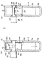
図4および図5は本発明の他の実施の形態を示している。 4 and 5 show another embodiment of the present invention.
本実施の形態が前記実施の形態と異なる点は、切替弁6Aの構造である。
すなわち、切替弁6Aのハウジング10Aには、EGR管4に取り込まれたEGRガスが流入する流入口11と、EGRガスが流出する流出口12と、EGRガスをEGRクーラへ導入する導入口13と、が形成されている。
流入口11と流出口12とはハウジング10Aの側壁において互いに直角に位置するように開口している。流入口11と対向した第一隔壁21には、導入口13と導出口14とが隣り合わせに配置されている。
The present embodiment is different from the above embodiment in the structure of the switching
In other words, the housing 10A of the switching
The inflow port 11 and the
ハウジング10A内には、流入口11と導入口13とを連通させる第一流路15と、流出口12と導出口14とを連通させる第二流路16と、第一流路15と第二流路16とを連通させるクーラ流路17とが形成されている。クーラ流路17にはバランス口18が設けられている。バランス口18は第一隔壁21の中央部において直角に交差するように形成された第二隔壁22に開設されている。
In the housing 10A, a
第一流路15と第二流路16との接続部には、流路弁口19が形成されており、流路弁口19はバランス口18と一直線上で並んでいる。バランス口18は導入口13と導出口14との間において直角に配置された状態になっている。
導入口13と導出口14とバランス口18と流路弁口19とは、開口形状が互いに略同一の形状に形成されており、これらの開口縁辺部には導入口弁座13a、導出口弁座14a、バランス口弁座18a、流路弁口弁座19aが形成されている。
A flow
The
第一隔壁21と第二隔壁22との交差部にはバルブシャフト23が配置されており、バルブシャフト23は第一流路15および第二流路16と直角に架設されている。
バルブシャフト23の中間部には長方形の平板形状に形成されたバタフライバルブ26が、直交するように配置されてボルト27によって締結されている。
バタフライバルブ26におけるバルブシャフト23の両脇には、一対の弁体部26a、26bが形成されており、両弁体部26a、26bの形状は導入口13、導出口14、バランス口18および流路弁口19の開口形状に大きめに相似している。
一対の弁体部26a、26bは導入口弁座13a、導出口弁座14a、バランス口弁座18a、流路弁口弁座19aに離座および着座することにより、導入口13、導出口14、バランス口18および流路弁口19を開閉するように構成されている。
A
A
A pair of
The pair of
次に、以上の構成に係る切替弁6Aの作用および効果を説明する。
Next, the operation and effect of the switching
エンジン1の冷却水温が所定温度以下である場合(冷間時)には、図4に示されているように、バタフライバルブ26の両弁体部26a、26bが導入口弁座13a、導出口弁座14aに着座するとともに、バランス口弁座18a、流路弁口弁座19aから離座することにより、導入口13、導出口14を閉鎖し、バランス口18、流路弁口19を開放した状態になっている。
したがって、EGR管4から流入口11に流れ込んだEGRガスは、第一流路15および第二流路16を通って流出口12から流れ出して、吸気通路2へ供給される。
このように、冷間時には、EGRガスはEGRクーラ5を通過することなくそのまま給気通路2へ供給される。
When the cooling water temperature of the engine 1 is equal to or lower than a predetermined temperature (when cold), as shown in FIG. 4, both
Therefore, the EGR gas flowing into the inlet 11 from the
Thus, when cold, the EGR gas is supplied to the
この際には、第一流路15のEGRガスの圧力がバタフライバルブ26の一方の弁体部26aを導入口弁座13aに着座させるとともに、バタフライバルブ26の他方の弁体部26bを導出口弁座14aに着座させるために、導入口13、導出口14を確実に閉鎖することができるとともに、エンジン1による排気ガスの脈動の影響を抑制することができる。
つまり、両弁体部26a、26bは常に略同じ圧力を受けるため、エンジン1による排気ガスの脈動により圧力が増減しても、バタフライバルブ26が開閉することはない。
したがって、流入口11からハウジング10に流入したEGRガスは、EGRクーラ5側へ漏れることなく吸気通路2側へ全て流れる。
At this time, the pressure of the EGR gas in the
That is, since both
Therefore, the EGR gas that has flowed into the
冷却水温が所定温度以上になると(暖気後)、ロータリーアクチュエータ25(図3参照)により、バルブシャフト23が90度回動され、図5に示されているように、バタフライバルブ26の両弁体部26a、26bがバランス口弁座18a、流路弁口弁座19aに着座するとともに、導入口弁座13a、導出口弁座14aから離座することにより、バランス口18、流路弁口19を閉鎖するとともに、導入口13、導出口14を開放した状態になる。
したがって、EGR管4から流入口11に流れ込んだEGRガスは、導入口13からEGRクーラ5へ供給される。そして、EGRクーラ5によって冷却されたEGRガスは、吸気通路2へ供給される。
When the cooling water temperature becomes equal to or higher than the predetermined temperature (after warming up), the
Therefore, the EGR gas that has flowed into the inlet 11 from the
この際には、第一流路15のEGRガスの圧力がバタフライバルブ26の一方の弁体部26aを流路弁口弁座19aに着座させるとともに、第二流路16のEGRガスの圧力がバタフライバルブ26の他方の弁体部26bをバランス口弁座18aに着座させるので、流路弁口19、バランス口18を確実に閉鎖することができるとともに、エンジン1による排気ガスの脈動の影響を抑制することができる。
つまり、両弁体部26a、26bは常に略同じ圧力を受けるため、エンジン1による排気ガスの脈動により圧力が増減しても、バタフライバルブ26が開閉することはない。
したがって、流入口11からハウジング10に流入したEGRガスは、第二流路16側へ漏れることなくEGRクーラ5側へ全て流れるので、高い冷却効率が得られる。
また、排気ガスの脈動を抑制することができるため、アクチュエータを小型化することができる。
At this time, the pressure of the EGR gas in the
That is, since both
Therefore, since all the EGR gas that has flowed into the
Moreover, since the pulsation of the exhaust gas can be suppressed, the actuator can be downsized.
なお、本発明は前記実施の形態に限定されるものではなく、その要旨を逸脱しない範囲で種々に変更が可能であることはいうまでもない。 Needless to say, the present invention is not limited to the above-described embodiment, and various modifications can be made without departing from the scope of the invention.
例えば、バルブシャフト23の位置は、バタフライバルブ26の中心線上が望ましいが、多少偏心していてもよい。
For example, the position of the
また、両弁体部26a、26bは、略同一形状ではなく、略同一面積となるようにしてもよい。
Moreover, you may make it the both
バルブシャフト23はロータリーアクチュエータの他、リンク機構を介してオンオフ式アクチュエータにより、往復回動させてもよい。
The
1…エンジン、2…吸気通路、3…排気通路、4…EGR管、5…EGRクーラ、5a…区画壁、5b…流路、6、6A…切替弁、
10、10A…ハウジング、11…流入口、12…流出口、13…導入口、13a…導入口弁座、14…導出口、14a…導出口弁座、15…第一流路、16…第二流路、17…クーラ流路、18…バランス口、18a…バランス口弁座、19…流路弁口、19a…流路弁口弁座、
21…第一隔壁、22…第二隔壁、23…バルブシャフト、24…軸受部、25…ロータリーアクチュエータ、26…バタフライバルブ、26a、26b…弁体部、27…ボルト。
DESCRIPTION OF SYMBOLS 1 ... Engine, 2 ... Intake passage, 3 ... Exhaust passage, 4 ... EGR pipe, 5 ... EGR cooler, 5a ... Partition wall, 5b ... Flow path, 6, 6A ... Switching valve,
DESCRIPTION OF
DESCRIPTION OF
Claims (4)
前記吸気通路と前記排気通路とを連通させる第一流路と、前記排気通路と前記EGRクーラとを連通させる第二流路と、第一流路と第二流路とを連通させるクーラ流路とが形成されたハウジングを備えており、
前記第一流路と前記第二流路と前記クーラ流路との交差部にはバルブシャフトが架設されており、該バルブシャフトには一対の弁体部を有するバタフライバルブが固定されており、
該バタフライバルブは、前記一対の弁体部の一方が前記クーラ流路の入口を閉じている時に、他方の弁体部が前記クーラ流路の出口を閉じるように、かつ、一方の弁体部が前記第一流路と前記第二流路とを遮断している時に、他方の弁体部が前記クーラ流路を開くように、構成されており、
前記第一流路と前記第二流路との接続部には流路弁口が形成され、該流路弁口の前記一方の弁体部が対向する側の開口縁辺部には流路弁口弁座が形成されており、
前記クーラ流路にはバランス口が形成され、該バランス口の前記他方の弁体部が対向する側の開口縁辺部にはバランス口弁座が前記流路弁口弁座と対向して形成されており、
前記流路弁口弁座と前記バランス口弁座は前記バルブシャフトを中心とした回転対称位置で前記バタフライバルブの厚さ分ずれて配置されている、
ことを特徴とする排気ガス再循環装置。 In an exhaust gas recirculation device in which an EGR cooler is provided in an exhaust gas recirculation passage connecting an intake passage and an exhaust passage of an engine,
A first flow path for communicating the intake passage and the exhaust path, a second flow path for communicating the exhaust path and the EGR cooler, and a cooler flow path for communicating the first flow path and the second flow path. A formed housing,
A valve shaft is installed at the intersection of the first flow path, the second flow path, and the cooler flow path, and a butterfly valve having a pair of valve body portions is fixed to the valve shaft.
The butterfly valve is configured such that when one of the pair of valve bodies closes the inlet of the cooler flow path, the other valve body closes the outlet of the cooler flow path, and one valve body section Is configured such that when the first flow path and the second flow path are shut off, the other valve body portion opens the cooler flow path ,
A flow path valve port is formed at a connection portion between the first flow path and the second flow path, and a flow path valve port is formed at an opening edge of the flow path valve port on the side facing the one valve body portion. A valve seat is formed,
A balance port is formed in the cooler flow path, and a balance port valve seat is formed to face the flow path valve seat valve seat at an opening edge portion of the balance port on the side facing the other valve body portion. And
The flow path valve seat and the balance port valve seat are arranged at a rotationally symmetrical position about the valve shaft and shifted by the thickness of the butterfly valve;
An exhaust gas recirculation device.
前記導出口の前記バタフライバルブにおける前記一対の弁体部の他方が対向する側の開口縁辺部には導出口弁座が形成されており、
前記導入口弁座と前記導出口弁座は前記バルブシャフトを中心とした回転対称位置で前記バタフライバルブの厚さの分ずれて配置されている、
ことを特徴とする請求項1に記載の排気ガス再循環装置。 An inlet and an outlet are respectively formed at an inlet and an outlet of the cooler channel, and an inlet is provided at an opening edge of the inlet facing the one of the pair of valve bodies in the butterfly valve. A valve seat is formed,
An outlet valve seat is formed on the opening edge of the outlet port on the side opposite to the other of the pair of valve body portions in the butterfly valve,
The inlet valve seat and the outlet valve seat are arranged at a rotationally symmetrical position about the valve shaft and are shifted by the thickness of the butterfly valve;
The exhaust gas recirculation device according to claim 1.
前記流入口と前記流出口とは互いに対向されており、前記導入口と前記導出口とは隣り合わせに配置されている、
ことを特徴とする請求項1または2に記載の排気ガス再循環装置。 The housing discharges the EGR cooler gas that has passed through the EGR cooler, the inlet through which the EGR gas flows in, the outlet through which the EGR gas or EGR cooler gas flows out, the inlet that introduces the EGR gas into the EGR cooler, and the EGR cooler. A lead-out port is formed,
The inflow port and the outflow port are opposed to each other, and the introduction port and the outflow port are disposed adjacent to each other,
The exhaust gas recirculation device according to claim 1 or 2, characterized in that
前記流入口と前記流出口とは互いに直角に位置されており、前記導入口と前記導出口とは隣り合わせに配置されている、
ことを特徴とする請求項1または2に記載の排気ガス再循環装置。 The housing is formed with an inlet through which EGR gas flows in, an outlet through which EGR gas flows out, and an inlet through which EGR gas is introduced into the EGR cooler,
The inflow port and the outflow port are positioned at right angles to each other, and the introduction port and the outflow port are arranged next to each other,
The exhaust gas recirculation device according to claim 1 or 2, characterized in that
Priority Applications (1)
| Application Number | Priority Date | Filing Date | Title |
|---|---|---|---|
| JP2007262132A JP4974835B2 (en) | 2007-10-05 | 2007-10-05 | Exhaust gas recirculation device |
Applications Claiming Priority (1)
| Application Number | Priority Date | Filing Date | Title |
|---|---|---|---|
| JP2007262132A JP4974835B2 (en) | 2007-10-05 | 2007-10-05 | Exhaust gas recirculation device |
Publications (3)
| Publication Number | Publication Date |
|---|---|
| JP2009091947A JP2009091947A (en) | 2009-04-30 |
| JP2009091947A5 JP2009091947A5 (en) | 2010-11-18 |
| JP4974835B2 true JP4974835B2 (en) | 2012-07-11 |
Family
ID=40664183
Family Applications (1)
| Application Number | Title | Priority Date | Filing Date |
|---|---|---|---|
| JP2007262132A Active JP4974835B2 (en) | 2007-10-05 | 2007-10-05 | Exhaust gas recirculation device |
Country Status (1)
| Country | Link |
|---|---|
| JP (1) | JP4974835B2 (en) |
Families Citing this family (4)
| Publication number | Priority date | Publication date | Assignee | Title |
|---|---|---|---|---|
| US9664087B2 (en) | 2010-07-22 | 2017-05-30 | Wescast Industries, Inc. | Exhaust heat recovery system with bypass |
| JP2012132337A (en) * | 2010-12-20 | 2012-07-12 | Toyota Motor Corp | Control device of internal combustion engine with supercharger |
| EP2766687B1 (en) * | 2011-09-09 | 2019-04-24 | Dana Canada Corporation | Stacked plate exhaust gas recovery device |
| EP2803843B1 (en) * | 2013-05-14 | 2018-02-14 | Bosal Emission Control Systems NV | Unit for recovering thermal energy from exhaust gas of an internal combustion engine |
Family Cites Families (1)
| Publication number | Priority date | Publication date | Assignee | Title |
|---|---|---|---|---|
| EP1913324B1 (en) * | 2005-07-19 | 2011-09-14 | Behr GmbH & Co. KG | Heat exchanger |
-
2007
- 2007-10-05 JP JP2007262132A patent/JP4974835B2/en active Active
Also Published As
| Publication number | Publication date |
|---|---|
| JP2009091947A (en) | 2009-04-30 |
Similar Documents
| Publication | Publication Date | Title |
|---|---|---|
| JP4468277B2 (en) | Flow path switching valve | |
| US9121316B2 (en) | Exhaust gas heat recovery device | |
| RU2718387C2 (en) | System (versions) and method for cooler of exhaust gas recirculation system | |
| US8061309B2 (en) | Cooling system | |
| JP5001752B2 (en) | EGR cooler bypass switching system | |
| JP2007263034A (en) | Engine cooling water circuit | |
| US20070271910A1 (en) | Heat Exchange Tube Bundle for Regulating the Temperature of the Gases Entering an Internal Combustion Engine of a Motor Vehicle | |
| US7845339B2 (en) | Exhaust gas recirculation cooler coolant plumbing configuration | |
| KR20110046089A (en) | Exhaust gas recirculation apparatus | |
| JP4974835B2 (en) | Exhaust gas recirculation device | |
| JP2002227646A (en) | Engine with egr cooler | |
| JP2007100665A (en) | Exhaust gas passage structure for internal combustion engine | |
| JP2006090167A (en) | Exhaust gas recirculation device for engine | |
| KR101758212B1 (en) | Exhaust gas heat exchanger capable of controlling cooling performance | |
| JP2021161979A (en) | Egr system of engine | |
| WO2013011767A1 (en) | Engine cooling circuit | |
| JP2009085094A (en) | Exhaust gas recirculation device for engine | |
| JP2012026296A (en) | Egr cooler system and flow path selector valve | |
| JPH10325368A (en) | Egr gas cooling device | |
| JP5918474B2 (en) | EGR device | |
| JP2021161980A (en) | Egr system of engine | |
| JP2004257322A (en) | Egr device of engine | |
| JP2009091925A (en) | Engine exhaust recirculating device | |
| JP2016079890A (en) | Engine cooling device | |
| KR101977900B1 (en) | Exhaust gas heat exchanger capable of controlling cooling performance and differential pressure |
Legal Events
| Date | Code | Title | Description |
|---|---|---|---|
| A521 | Request for written amendment filed |
Free format text: JAPANESE INTERMEDIATE CODE: A523 Effective date: 20100930 |
|
| A621 | Written request for application examination |
Free format text: JAPANESE INTERMEDIATE CODE: A621 Effective date: 20100930 |
|
| A131 | Notification of reasons for refusal |
Free format text: JAPANESE INTERMEDIATE CODE: A131 Effective date: 20111213 |
|
| A521 | Request for written amendment filed |
Free format text: JAPANESE INTERMEDIATE CODE: A523 Effective date: 20120209 |
|
| TRDD | Decision of grant or rejection written | ||
| A01 | Written decision to grant a patent or to grant a registration (utility model) |
Free format text: JAPANESE INTERMEDIATE CODE: A01 Effective date: 20120410 |
|
| A01 | Written decision to grant a patent or to grant a registration (utility model) |
Free format text: JAPANESE INTERMEDIATE CODE: A01 |
|
| A61 | First payment of annual fees (during grant procedure) |
Free format text: JAPANESE INTERMEDIATE CODE: A61 Effective date: 20120410 |
|
| R150 | Certificate of patent or registration of utility model |
Free format text: JAPANESE INTERMEDIATE CODE: R150 Ref document number: 4974835 Country of ref document: JP Free format text: JAPANESE INTERMEDIATE CODE: R150 |
|
| FPAY | Renewal fee payment (event date is renewal date of database) |
Free format text: PAYMENT UNTIL: 20150420 Year of fee payment: 3 |
|
| S531 | Written request for registration of change of domicile |
Free format text: JAPANESE INTERMEDIATE CODE: R313531 |
|
| R350 | Written notification of registration of transfer |
Free format text: JAPANESE INTERMEDIATE CODE: R350 |
|
| R250 | Receipt of annual fees |
Free format text: JAPANESE INTERMEDIATE CODE: R250 |
|
| R250 | Receipt of annual fees |
Free format text: JAPANESE INTERMEDIATE CODE: R250 |
|
| R250 | Receipt of annual fees |
Free format text: JAPANESE INTERMEDIATE CODE: R250 |
|
| R250 | Receipt of annual fees |
Free format text: JAPANESE INTERMEDIATE CODE: R250 |
|
| R250 | Receipt of annual fees |
Free format text: JAPANESE INTERMEDIATE CODE: R250 |
|
| R250 | Receipt of annual fees |
Free format text: JAPANESE INTERMEDIATE CODE: R250 |
|
| R250 | Receipt of annual fees |
Free format text: JAPANESE INTERMEDIATE CODE: R250 |
|
| R250 | Receipt of annual fees |
Free format text: JAPANESE INTERMEDIATE CODE: R250 |
|
| R250 | Receipt of annual fees |
Free format text: JAPANESE INTERMEDIATE CODE: R250 |
|
| R250 | Receipt of annual fees |
Free format text: JAPANESE INTERMEDIATE CODE: R250 |