EP2766575B1 - Piston pump/ -motor - Google Patents
Piston pump/ -motor Download PDFInfo
- Publication number
- EP2766575B1 EP2766575B1 EP12788304.9A EP12788304A EP2766575B1 EP 2766575 B1 EP2766575 B1 EP 2766575B1 EP 12788304 A EP12788304 A EP 12788304A EP 2766575 B1 EP2766575 B1 EP 2766575B1
- Authority
- EP
- European Patent Office
- Prior art keywords
- plunger
- hole
- motor
- pump
- casing
- Prior art date
- Legal status (The legal status is an assumption and is not a legal conclusion. Google has not performed a legal analysis and makes no representation as to the accuracy of the status listed.)
- Not-in-force
Links
- 238000004891 communication Methods 0.000 claims description 21
- 239000007788 liquid Substances 0.000 description 10
- 238000010276 construction Methods 0.000 description 4
- 230000007246 mechanism Effects 0.000 description 4
- 238000009835 boiling Methods 0.000 description 3
- 230000006835 compression Effects 0.000 description 3
- 238000007906 compression Methods 0.000 description 3
- 238000005086 pumping Methods 0.000 description 3
- 230000009471 action Effects 0.000 description 1
- 230000008878 coupling Effects 0.000 description 1
- 238000010168 coupling process Methods 0.000 description 1
- 238000005859 coupling reaction Methods 0.000 description 1
- 238000005265 energy consumption Methods 0.000 description 1
- 238000005516 engineering process Methods 0.000 description 1
- 230000000266 injurious effect Effects 0.000 description 1
- 238000012423 maintenance Methods 0.000 description 1
- 238000000034 method Methods 0.000 description 1
- 239000000203 mixture Substances 0.000 description 1
- 230000008569 process Effects 0.000 description 1
Images


Classifications
-
- F—MECHANICAL ENGINEERING; LIGHTING; HEATING; WEAPONS; BLASTING
- F15—FLUID-PRESSURE ACTUATORS; HYDRAULICS OR PNEUMATICS IN GENERAL
- F15B—SYSTEMS ACTING BY MEANS OF FLUIDS IN GENERAL; FLUID-PRESSURE ACTUATORS, e.g. SERVOMOTORS; DETAILS OF FLUID-PRESSURE SYSTEMS, NOT OTHERWISE PROVIDED FOR
- F15B15/00—Fluid-actuated devices for displacing a member from one position to another; Gearing associated therewith
- F15B15/02—Mechanical layout characterised by the means for converting the movement of the fluid-actuated element into movement of the finally-operated member
-
- F—MECHANICAL ENGINEERING; LIGHTING; HEATING; WEAPONS; BLASTING
- F01—MACHINES OR ENGINES IN GENERAL; ENGINE PLANTS IN GENERAL; STEAM ENGINES
- F01B—MACHINES OR ENGINES, IN GENERAL OR OF POSITIVE-DISPLACEMENT TYPE, e.g. STEAM ENGINES
- F01B11/00—Reciprocating-piston machines or engines without rotary main shaft, e.g. of free-piston type
- F01B11/001—Reciprocating-piston machines or engines without rotary main shaft, e.g. of free-piston type in which the movement in the two directions is obtained by one double acting piston motor
- F01B11/002—Reciprocating-piston machines or engines without rotary main shaft, e.g. of free-piston type in which the movement in the two directions is obtained by one double acting piston motor one side of the double acting piston motor being always under the influence of the fluid under pressure
-
- F—MECHANICAL ENGINEERING; LIGHTING; HEATING; WEAPONS; BLASTING
- F01—MACHINES OR ENGINES IN GENERAL; ENGINE PLANTS IN GENERAL; STEAM ENGINES
- F01B—MACHINES OR ENGINES, IN GENERAL OR OF POSITIVE-DISPLACEMENT TYPE, e.g. STEAM ENGINES
- F01B11/00—Reciprocating-piston machines or engines without rotary main shaft, e.g. of free-piston type
- F01B11/007—Reciprocating-piston machines or engines without rotary main shaft, e.g. of free-piston type in which the movement in only one direction is obtained by a single acting piston motor, e.g. with actuation in the other direction by spring means
-
- F—MECHANICAL ENGINEERING; LIGHTING; HEATING; WEAPONS; BLASTING
- F03—MACHINES OR ENGINES FOR LIQUIDS; WIND, SPRING, OR WEIGHT MOTORS; PRODUCING MECHANICAL POWER OR A REACTIVE PROPULSIVE THRUST, NOT OTHERWISE PROVIDED FOR
- F03C—POSITIVE-DISPLACEMENT ENGINES DRIVEN BY LIQUIDS
- F03C1/00—Reciprocating-piston liquid engines
- F03C1/007—Reciprocating-piston liquid engines with single cylinder, double-acting piston
- F03C1/0073—Reciprocating-piston liquid engines with single cylinder, double-acting piston one side of the double-acting piston being always under the influence of the liquid under pressure
-
- F—MECHANICAL ENGINEERING; LIGHTING; HEATING; WEAPONS; BLASTING
- F03—MACHINES OR ENGINES FOR LIQUIDS; WIND, SPRING, OR WEIGHT MOTORS; PRODUCING MECHANICAL POWER OR A REACTIVE PROPULSIVE THRUST, NOT OTHERWISE PROVIDED FOR
- F03C—POSITIVE-DISPLACEMENT ENGINES DRIVEN BY LIQUIDS
- F03C1/00—Reciprocating-piston liquid engines
- F03C1/02—Reciprocating-piston liquid engines with multiple-cylinders, characterised by the number or arrangement of cylinders
- F03C1/03—Reciprocating-piston liquid engines with multiple-cylinders, characterised by the number or arrangement of cylinders with movement in two directions being obtained by two single-acting piston liquid engines, each acting in one direction
- F03C1/035—Reciprocating-piston liquid engines with multiple-cylinders, characterised by the number or arrangement of cylinders with movement in two directions being obtained by two single-acting piston liquid engines, each acting in one direction one single-acting piston being always under the influence of the liquid under pressure
-
- F—MECHANICAL ENGINEERING; LIGHTING; HEATING; WEAPONS; BLASTING
- F04—POSITIVE - DISPLACEMENT MACHINES FOR LIQUIDS; PUMPS FOR LIQUIDS OR ELASTIC FLUIDS
- F04B—POSITIVE-DISPLACEMENT MACHINES FOR LIQUIDS; PUMPS
- F04B15/00—Pumps adapted to handle specific fluids, e.g. by selection of specific materials for pumps or pump parts
- F04B15/06—Pumps adapted to handle specific fluids, e.g. by selection of specific materials for pumps or pump parts for liquids near their boiling point, e.g. under subnormal pressure
-
- F—MECHANICAL ENGINEERING; LIGHTING; HEATING; WEAPONS; BLASTING
- F04—POSITIVE - DISPLACEMENT MACHINES FOR LIQUIDS; PUMPS FOR LIQUIDS OR ELASTIC FLUIDS
- F04B—POSITIVE-DISPLACEMENT MACHINES FOR LIQUIDS; PUMPS
- F04B9/00—Piston machines or pumps characterised by the driving or driven means to or from their working members
- F04B9/08—Piston machines or pumps characterised by the driving or driven means to or from their working members the means being fluid
-
- F—MECHANICAL ENGINEERING; LIGHTING; HEATING; WEAPONS; BLASTING
- F04—POSITIVE - DISPLACEMENT MACHINES FOR LIQUIDS; PUMPS FOR LIQUIDS OR ELASTIC FLUIDS
- F04B—POSITIVE-DISPLACEMENT MACHINES FOR LIQUIDS; PUMPS
- F04B9/00—Piston machines or pumps characterised by the driving or driven means to or from their working members
- F04B9/08—Piston machines or pumps characterised by the driving or driven means to or from their working members the means being fluid
- F04B9/10—Piston machines or pumps characterised by the driving or driven means to or from their working members the means being fluid the fluid being liquid
- F04B9/103—Piston machines or pumps characterised by the driving or driven means to or from their working members the means being fluid the fluid being liquid having only one pumping chamber
- F04B9/107—Piston machines or pumps characterised by the driving or driven means to or from their working members the means being fluid the fluid being liquid having only one pumping chamber rectilinear movement of the pumping member in the working direction being obtained by a single-acting liquid motor, e.g. actuated in the other direction by gravity or a spring
-
- F—MECHANICAL ENGINEERING; LIGHTING; HEATING; WEAPONS; BLASTING
- F04—POSITIVE - DISPLACEMENT MACHINES FOR LIQUIDS; PUMPS FOR LIQUIDS OR ELASTIC FLUIDS
- F04B—POSITIVE-DISPLACEMENT MACHINES FOR LIQUIDS; PUMPS
- F04B9/00—Piston machines or pumps characterised by the driving or driven means to or from their working members
- F04B9/08—Piston machines or pumps characterised by the driving or driven means to or from their working members the means being fluid
- F04B9/10—Piston machines or pumps characterised by the driving or driven means to or from their working members the means being fluid the fluid being liquid
- F04B9/103—Piston machines or pumps characterised by the driving or driven means to or from their working members the means being fluid the fluid being liquid having only one pumping chamber
- F04B9/107—Piston machines or pumps characterised by the driving or driven means to or from their working members the means being fluid the fluid being liquid having only one pumping chamber rectilinear movement of the pumping member in the working direction being obtained by a single-acting liquid motor, e.g. actuated in the other direction by gravity or a spring
- F04B9/1076—Piston machines or pumps characterised by the driving or driven means to or from their working members the means being fluid the fluid being liquid having only one pumping chamber rectilinear movement of the pumping member in the working direction being obtained by a single-acting liquid motor, e.g. actuated in the other direction by gravity or a spring with fluid-actuated inlet or outlet valve
-
- F—MECHANICAL ENGINEERING; LIGHTING; HEATING; WEAPONS; BLASTING
- F04—POSITIVE - DISPLACEMENT MACHINES FOR LIQUIDS; PUMPS FOR LIQUIDS OR ELASTIC FLUIDS
- F04B—POSITIVE-DISPLACEMENT MACHINES FOR LIQUIDS; PUMPS
- F04B9/00—Piston machines or pumps characterised by the driving or driven means to or from their working members
- F04B9/08—Piston machines or pumps characterised by the driving or driven means to or from their working members the means being fluid
- F04B9/12—Piston machines or pumps characterised by the driving or driven means to or from their working members the means being fluid the fluid being elastic, e.g. steam or air
- F04B9/123—Piston machines or pumps characterised by the driving or driven means to or from their working members the means being fluid the fluid being elastic, e.g. steam or air having only one pumping chamber
- F04B9/127—Piston machines or pumps characterised by the driving or driven means to or from their working members the means being fluid the fluid being elastic, e.g. steam or air having only one pumping chamber rectilinear movement of the pumping member in the working direction being obtained by a single-acting elastic-fluid motor, e.g. actuated in the other direction by gravity or a spring
-
- F—MECHANICAL ENGINEERING; LIGHTING; HEATING; WEAPONS; BLASTING
- F04—POSITIVE - DISPLACEMENT MACHINES FOR LIQUIDS; PUMPS FOR LIQUIDS OR ELASTIC FLUIDS
- F04B—POSITIVE-DISPLACEMENT MACHINES FOR LIQUIDS; PUMPS
- F04B9/00—Piston machines or pumps characterised by the driving or driven means to or from their working members
- F04B9/08—Piston machines or pumps characterised by the driving or driven means to or from their working members the means being fluid
- F04B9/12—Piston machines or pumps characterised by the driving or driven means to or from their working members the means being fluid the fluid being elastic, e.g. steam or air
- F04B9/123—Piston machines or pumps characterised by the driving or driven means to or from their working members the means being fluid the fluid being elastic, e.g. steam or air having only one pumping chamber
- F04B9/127—Piston machines or pumps characterised by the driving or driven means to or from their working members the means being fluid the fluid being elastic, e.g. steam or air having only one pumping chamber rectilinear movement of the pumping member in the working direction being obtained by a single-acting elastic-fluid motor, e.g. actuated in the other direction by gravity or a spring
- F04B9/1276—Piston machines or pumps characterised by the driving or driven means to or from their working members the means being fluid the fluid being elastic, e.g. steam or air having only one pumping chamber rectilinear movement of the pumping member in the working direction being obtained by a single-acting elastic-fluid motor, e.g. actuated in the other direction by gravity or a spring with fluid-actuated inlet or outlet valve
-
- F—MECHANICAL ENGINEERING; LIGHTING; HEATING; WEAPONS; BLASTING
- F15—FLUID-PRESSURE ACTUATORS; HYDRAULICS OR PNEUMATICS IN GENERAL
- F15B—SYSTEMS ACTING BY MEANS OF FLUIDS IN GENERAL; FLUID-PRESSURE ACTUATORS, e.g. SERVOMOTORS; DETAILS OF FLUID-PRESSURE SYSTEMS, NOT OTHERWISE PROVIDED FOR
- F15B9/00—Servomotors with follow-up action, e.g. obtained by feed-back control, i.e. in which the position of the actuated member conforms with that of the controlling member
- F15B9/02—Servomotors with follow-up action, e.g. obtained by feed-back control, i.e. in which the position of the actuated member conforms with that of the controlling member with servomotors of the reciprocatable or oscillatable type
- F15B9/08—Servomotors with follow-up action, e.g. obtained by feed-back control, i.e. in which the position of the actuated member conforms with that of the controlling member with servomotors of the reciprocatable or oscillatable type controlled by valves affecting the fluid feed or the fluid outlet of the servomotor
Definitions
- the invention relates to a plunger pump / plunger motor comprising a motor casing having a first cylindrical chamber and a plunger movable in this chamber with a drive shaft attached to a first plunger side, so that the plunger surface on the first side is smaller than on an opposite second side, a first and a second hole being provided in the motor casing at such a location that in any position of the plunger one hole is available on either side of the plunger, and which plunger pump / plunger motor comprises a valve including a valve casing having a second cylindrical chamber and a control valve movable in this chamber, which valve can establish a communication between a connecting hole for a delivery pipe and the second hole.
- the drive shaft drives for example a mechanism that converts a translating movement into a rotating movement
- the drive shaft drives for example a piston that provides the pumping action
- a plunger pump / plunger motor of this type is generally known.
- the valve has a separate power supply for the purpose of moving the control valve.
- the DE 1 249 594 is considered as being the closest prior art and discloses all the features of the preamble of claim 1.
- the plunger pump / plunger motor according to the invention is characterized in that the valve casing has a first further hole and a second further hole at such a location that in any position of the control valve one further hole is available on either side of the control valve, while furthermore the motor casing has a third and a fourth hole, where the third hole communicates with the first further hole in the valve casing and the fourth hole communicates with the second further hole in the valve casing, which third and fourth holes can alternately be brought into communication with the connecting hole for the delivery pipe by the plunger.
- the operation of the valve in the plunger pump / plunger motor according to the invention does not require external power supply, but this valve is fed by the same delivery pipe as the one for feeding the plunger motor, so that a simple construction is obtained.
- the plunger pump / plunger motor according to the invention is pre-eminently suitable for circulating boiling liquids.
- Boiling liquids are often circulated by means of rotating pumps (centrifugal and side channel or a combination thereof) which are coupled to an electric drive motor. Owing to the injurious effect of the liquid to be circulated on humans and the environment, the coupling between pump and motor is to be leak-proof.
- pumper drums are utilized, which are called montejus in process technology.
- compressed gas or flash gas is then used in lieu of compressed air.
- a disadvantage of this solution is that many fittings are needed, that the solution is energetically poor and that delivery is effected periodically.
- the plunger pump / plunger motor according to the invention provides a cost effective solution for circulating boiling liquids with:
- Condition 1 is satisfied by making use of a flash gas fed expander motor, condition 2 is satisfied by minimizing the flow losses in the pump and condition 3 is satisfied by striving for a minimum number of component parts (hence also the low cost price) which move with little friction.
- An embodiment of the plunger pump / plunger motor according to the invention is characterized in that the third and the fourth hole are alternately brought into communication with the environment or with a connecting hole for a delivery pipe by the plunger, so that no further provisions need to be made for this.
- the motor casing further has a fifth and a sixth hole which communicate with the environment or with the connecting hole for the delivery pipe and the plunger can alternately establish a communication between the third and the fourth hole and the fifth and the sixth hole.
- the plunger pump / plunger motor is preferably constructed such that the control valve can establish a communication between the second hole and the environment or the connecting hole for the delivery pipe.
- the valve casing preferably has a third further hole which communicates with the environment or with the connecting hole for the delivery pipe and the control valve can establish a communication between the second hole and the third further hole.
- An embodiment of the plunger pump / plunger motor according to the invention in which this embodiment is arranged as a plunger pump is characterized in that the drive shaft is connected to a further plunger which is movable in a third cylindrical chamber which is located in a pump casing in which a suction hole / delivery hole is present.
- control valve can alternately be brought into communication with a connecting hole for a suction pipe and the connecting hole for the delivery pipe.
- a further embodiment of the plunger pump / plunger motor according to the invention is characterized in that the valve casing is provided with a fourth further hole which communicates with the suction hole /delivery hole, as well as a fifth further hole which communicates with the connecting hole for a suction pipe.
- a still further embodiment of the plunger pump / plunger motor according to the invention is characterized in that the third further hole communicates with the connecting hole for a delivery pipe.
- a compact and simple construction of the plunger pump / plunger motor according to the invention is characterized in that the motor casing and valve casing are constituted by a single block which accommodates the first and the second cylindrical chamber, and which block is provided with at least a single connecting hole to which the delivery pipe can be connected, as well as channels which connect the holes and further holes to each other and to the at least one connecting hole.
- a further compact and simple construction of the plunger pump / plunger motor according to the invention is characterized in that the block also constitutes the pump casing and is provided with two further connecting holes to which the suction pipe and the delivery pipe can be connected.
- An even simpler construction of the plunger pump / plunger motor according to the invention is characterized in that the plunger and the further plunger are attached to each other.
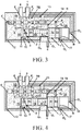
- Figs. 1 to 4 show a first embodiment of the plunger pump / plunger motor according to the invention arranged as a plunger pump shown in different stages of the pumping proces.
- the plunger pump / plunger motor comprises a motor casing 1A which accommodates a first cylindrical chamber 7 and a plunger 2 movable in this chamber.
- a drive shaft 19 To a first side A of the plunger 2 is attached a drive shaft 19, as a result of which the plunger surface on this first side A is smaller than on an opposite, second side B.
- the motor casing 1A is provided with a first hole and a second hole O 1 and O 2 at such a location that in any position of the plunger 2 one hole is available on either side of the plunger.
- the plunger pump / plunger motor further comprises a valve which has a valve casing 1B wich accommodates a second cylindrical chamber 7B and a control valve 3 movable in this chamber.
- This control valve can provide that a connecting hole 6 for a delivery pipe communicates with the second hole (O 2 .
- the valve casing 1B is provided with a first further hole and a second further hole F 1 and F 2 . These further holes are located at such a spot that in any position of the control valve 3 one further hole is available on either side of the control valve.
- the motor casing 1A is further provided with a third and a fourth hole O 3 and O 4 .
- the third hole O 3 communicates with the first further hole F 1 in the valve casing
- the fourth hole O 4 communicates with the second further hole F 2 in the valve casing.
- the third and fourth holes O 3 and O 4 can alternately be brought into communication with the connection 6 for the delivery pipe by the plunger 2.
- connection 6 for the delivery pipe is in permanent communication with the first hole O 1 .
- the third and fourth holes O 3 and O 4 can alternately be brought into communication with a connecting hole 5 for the delivery pipe by the plunger 2.
- the motor casing 1A is further provided with a fifth and a sixth hole O 5 and O 6 which communicate with the connecting hole 5 for the delivery pipe.
- the third and the fourth hole O 3 and O 4 can alternately be brought into communication with the fifth and sixth hole O 5 and O 6 respectively by the plunger 2.
- the control valve 3 can establish a communication between the second hole O 2 and the connecting hole 5 for the delivery pipe.
- the valve casing 1B is provided with a third further hole F 3 which communicates with the connecting hole 5 for the delivery pipe.
- the drive shaft 19 is connected to a further plunger 2a which is movable in a third cylindrical chamber 8 which is accommodated in a pump casing 1C in which a suction/delivery hole 9 is present.
- the control valve 3 can alternately establish a communication between the suction hole /delivery hole 9 and a connecting hole 4 for a suction pipe and a connecting hole 5 for a delivery pipe.
- the valve casing 1B is provided with a fourth further hole F 4 which communicates with the suction hole / delivery hole 9, as well as a fifth further hole F 5 which communicates with the connecting hole 4 for the suction pipe.
- the third further hole F 3 communicates with the connecting hole 5 for the delivery pipe.
- the motor casing 1A, the valve casing 1B and the pump casing 1C are constituted by a single block 1 in which the first, the second and the third cylindrical chambers 7, 7B and 8 are located.
- This block 1 is provided with three connecting holes 4, 5 and 6 to which the suction pipe, the delivery pipe and the pressure pipe can be connected.
- channels 12, 13, 16 and 17 which connect the holes O 1 , O 2 , O 3 , O 4 , O 5 and O 6 and further holes F 1 , F 2 , F 3 and F 4 to each other and to the three connecting holes.
- the plunger 2 and the further plunger 2a constitute a whole.
- the plunger pump / plunger motor comprises no more than two moving parts, that is to say, the plunger 2 with attached to it the further plunger 2a, and the control valve 3.
- the plunger 2 with the further plunger 2a attached to it is constituted by two parts, on the left there is the pumping part 2a and 2b and on the right there is the motor part 2c and 2d.
- the plunger and the control valve are coupled hydraulically, thus complex mechanisms and mechanisms subject to wear are absent.
- the ratio of pump diameter to motor diameter determines the lift of the pump and/or the number of strokes, thus the pump flow rate. The higher the difference in pressure over the motor with equal pump lift, the higher the pump flow rate.
- the feed of the motor takes place through the connecting hole 6 by means of a medium that has a higher pressure than the pump pressure.
- This may be liquid, gas or a biphase mixture.
- FIG. 1 the position of the control valve 3 and plunger 2 is shown substantially at the end of the suction stroke at the moment where the control valve 3 is going to be changed over and the slot 2b in plunger 2 starts to open the channel 12 so that a connection is created between channel 12 and channel 13 so that the pressure on the left hand side of the control valve 3 will decrease rapidly to the pump delivery pressure prevailing in the connecting hole 5 for the delivery pipe.
- FIG. 2 shows the situation in switched-over position.
- the control valve 3 changes over (cf. Fig. 4 ) and will discharge the motor of the pressure by opening up the channel 16 through slot 3c and channel 13 to the connecting hole 5 for the delivery pipe where the pump delivery pressure prevails.
- the pressure in the cylindrical chamber 7 compression spring
- Disc 3a functions as a change-over cock so as to have the liquid flow correctly during the suction stroke and delivery stroke.
- the discs 3b are used for balancing of pressure.
- the valve has a bore 3e.
- Fig. 5 shows a second embodiment of the plunger pump / plunger motor according to the invention, arranged as a plunger motor this time. All parts similar to those of the first embodiment or having a similar function to those of the first embodiment are referred to by like reference numerals.
- the pump section is lacking and the drive shaft 19 extends to beyond the block 1.
- This drive shaft is driven by the plunger 2 and can in its turn drive a shaft for example via a slotted link mechanism.
- the third and fourth holes O 3 and O 4 can alternately be brought into communication with the environment 18 in lieu of with a connecting hole for a delivery pipe
Landscapes
- Engineering & Computer Science (AREA)
- Mechanical Engineering (AREA)
- General Engineering & Computer Science (AREA)
- Physics & Mathematics (AREA)
- Fluid Mechanics (AREA)
- Chemical & Material Sciences (AREA)
- Combustion & Propulsion (AREA)
- Details Of Reciprocating Pumps (AREA)
- Reciprocating Pumps (AREA)
Applications Claiming Priority (2)
| Application Number | Priority Date | Filing Date | Title |
|---|---|---|---|
| NL2007584A NL2007584C2 (nl) | 2011-10-12 | 2011-10-12 | Plunjerpomp/-motor. |
| PCT/NL2012/050711 WO2013055215A1 (en) | 2011-10-12 | 2012-10-11 | Piston pump/ -motor |
Publications (2)
| Publication Number | Publication Date |
|---|---|
| EP2766575A1 EP2766575A1 (en) | 2014-08-20 |
| EP2766575B1 true EP2766575B1 (en) | 2016-04-06 |
Family
ID=47215699
Family Applications (1)
| Application Number | Title | Priority Date | Filing Date |
|---|---|---|---|
| EP12788304.9A Not-in-force EP2766575B1 (en) | 2011-10-12 | 2012-10-11 | Piston pump/ -motor |
Country Status (9)
| Country | Link |
|---|---|
| US (1) | US9599128B2 (enExample) |
| EP (1) | EP2766575B1 (enExample) |
| JP (1) | JP2014532143A (enExample) |
| CN (1) | CN103998717A (enExample) |
| DK (1) | DK2766575T3 (enExample) |
| IN (1) | IN2014KN00732A (enExample) |
| NL (1) | NL2007584C2 (enExample) |
| RU (1) | RU2014118571A (enExample) |
| WO (1) | WO2013055215A1 (enExample) |
Families Citing this family (2)
| Publication number | Priority date | Publication date | Assignee | Title |
|---|---|---|---|---|
| US11371331B2 (en) | 2017-12-28 | 2022-06-28 | Halliburton Energy Services, Inc. | Injection valve for injecting randomly sized and shaped items into high pressure lines |
| US20250327445A1 (en) * | 2024-04-17 | 2025-10-23 | Emerson Process Management Regulator Technologies, Inc. | Systems and methods for a gas-driven compressor |
Family Cites Families (8)
| Publication number | Priority date | Publication date | Assignee | Title |
|---|---|---|---|---|
| DE1086088B (de) * | 1957-11-14 | 1960-07-28 | Gewerk Eisenhuette Westfalia | Anlassvorrichtung fuer einen druckluft-betriebenen Kolbenwuchtmotor |
| DE1249594B (enExample) * | 1965-03-29 | 1967-09-07 | ||
| US4286929A (en) * | 1977-03-23 | 1981-09-01 | Rodney T. Heath | Dual pressure gas motor, and method of operation |
| WO1988009872A1 (en) * | 1987-06-12 | 1988-12-15 | Recovery Engineering, Inc. | Mixed-phase motor |
| DE3839449A1 (de) * | 1988-11-23 | 1990-05-31 | Daimler Benz Ag | Viertakt-brennkraftmaschine |
| CN1049471C (zh) * | 1996-02-02 | 2000-02-16 | 中南工业大学 | 液压冲击装置 |
| JP3574641B2 (ja) * | 2002-04-19 | 2004-10-06 | 株式会社イワキ | ポンプシステム |
| US7249458B2 (en) * | 2005-07-22 | 2007-07-31 | Ashradn Holdings Ltd. | Self-contained hydraulic actuator system |
-
2011
- 2011-10-12 NL NL2007584A patent/NL2007584C2/nl not_active IP Right Cessation
-
2012
- 2012-10-11 JP JP2014535681A patent/JP2014532143A/ja active Pending
- 2012-10-11 RU RU2014118571/06A patent/RU2014118571A/ru not_active Application Discontinuation
- 2012-10-11 EP EP12788304.9A patent/EP2766575B1/en not_active Not-in-force
- 2012-10-11 DK DK12788304.9T patent/DK2766575T3/en active
- 2012-10-11 CN CN201280061339.1A patent/CN103998717A/zh active Pending
- 2012-10-11 IN IN732KON2014 patent/IN2014KN00732A/en unknown
- 2012-10-11 WO PCT/NL2012/050711 patent/WO2013055215A1/en not_active Ceased
-
2014
- 2014-04-11 US US14/250,661 patent/US9599128B2/en not_active Expired - Fee Related
Also Published As
| Publication number | Publication date |
|---|---|
| RU2014118571A (ru) | 2015-11-20 |
| CN103998717A (zh) | 2014-08-20 |
| IN2014KN00732A (enExample) | 2015-10-02 |
| EP2766575A1 (en) | 2014-08-20 |
| US9599128B2 (en) | 2017-03-21 |
| JP2014532143A (ja) | 2014-12-04 |
| NL2007584C2 (nl) | 2012-12-05 |
| US20140311334A1 (en) | 2014-10-23 |
| WO2013055215A1 (en) | 2013-04-18 |
| DK2766575T3 (en) | 2016-07-18 |
Similar Documents
| Publication | Publication Date | Title |
|---|---|---|
| KR102699220B1 (ko) | 유압 펌프 제어 시스템 | |
| CN103930673B (zh) | 斜板式活塞泵 | |
| CN103174618A (zh) | 一种双作用式外转子的径向柱塞液压泵 | |
| US20150219215A1 (en) | Piston of axial piston pump motor, cylinder block of axial piston pump motor, and axial piston pump motor | |
| CN110821781A (zh) | 一种液压式空压机 | |
| TW201407039A (zh) | 壓力補償泵 | |
| CN109863300A (zh) | 具有入口折流件的液压泵 | |
| US9599128B2 (en) | Piston pump and motor | |
| CN110630461B (zh) | 一种变量径向柱塞泵 | |
| WO2019173133A1 (en) | Electro-hydraulic swashplate control arrangement for an axial piston pump | |
| CN109611308B (zh) | 一种高压变量柱塞泵 | |
| JP6539231B2 (ja) | 斜板式ピストンポンプ | |
| CN108167261B (zh) | 一种液压往复驱动机构及液压往复驱动泵 | |
| CN111043002B (zh) | 一种往复式柱塞泵 | |
| CN111043001B (zh) | 一种往复泵 | |
| KR20130048334A (ko) | 엔진 오일용 기계식 다단 가변 베인 펌프 | |
| CN111287923A (zh) | 一种井下注浆泵 | |
| CN208456793U (zh) | 往复式增压泵 | |
| US20090269227A1 (en) | Piston pump with at least one stepped piston element | |
| CN110630464B (zh) | 一种变排量高压泵 | |
| CN111140456A (zh) | 一种潜水泵 | |
| CN112814964A (zh) | 无阀换向装置及方法 | |
| US3335672A (en) | Multiple cartridge pumping apparatus | |
| CN115142819B (zh) | 石油井下伴生气的电液组合驱动加压排出装置及排出方法 | |
| CN111005852B (zh) | 一种高度集成的往复式柱塞泵 |
Legal Events
| Date | Code | Title | Description |
|---|---|---|---|
| PUAI | Public reference made under article 153(3) epc to a published international application that has entered the european phase |
Free format text: ORIGINAL CODE: 0009012 |
|
| 17P | Request for examination filed |
Effective date: 20140331 |
|
| AK | Designated contracting states |
Kind code of ref document: A1 Designated state(s): AL AT BE BG CH CY CZ DE DK EE ES FI FR GB GR HR HU IE IS IT LI LT LU LV MC MK MT NL NO PL PT RO RS SE SI SK SM TR |
|
| RIN1 | Information on inventor provided before grant (corrected) |
Inventor name: BARTHOLOMEUS, TITUS, MARIA CHRISTIAAN |
|
| RAP1 | Party data changed (applicant data changed or rights of an application transferred) |
Owner name: TH. WITT KAELTEMASCHINENFABRIK GMBH |
|
| DAX | Request for extension of the european patent (deleted) | ||
| GRAP | Despatch of communication of intention to grant a patent |
Free format text: ORIGINAL CODE: EPIDOSNIGR1 |
|
| INTG | Intention to grant announced |
Effective date: 20151016 |
|
| RAP1 | Party data changed (applicant data changed or rights of an application transferred) |
Owner name: THERMASS INNOVATIONS B.V. |
|
| GRAS | Grant fee paid |
Free format text: ORIGINAL CODE: EPIDOSNIGR3 |
|
| GRAA | (expected) grant |
Free format text: ORIGINAL CODE: 0009210 |
|
| AK | Designated contracting states |
Kind code of ref document: B1 Designated state(s): AL AT BE BG CH CY CZ DE DK EE ES FI FR GB GR HR HU IE IS IT LI LT LU LV MC MK MT NL NO PL PT RO RS SE SI SK SM TR |
|
| REG | Reference to a national code |
Ref country code: GB Ref legal event code: FG4D |
|
| REG | Reference to a national code |
Ref country code: AT Ref legal event code: REF Ref document number: 788059 Country of ref document: AT Kind code of ref document: T Effective date: 20160415 Ref country code: CH Ref legal event code: EP |
|
| REG | Reference to a national code |
Ref country code: IE Ref legal event code: FG4D |
|
| REG | Reference to a national code |
Ref country code: DE Ref legal event code: R096 Ref document number: 602012016764 Country of ref document: DE |
|
| REG | Reference to a national code |
Ref country code: DK Ref legal event code: T3 Effective date: 20160713 |
|
| REG | Reference to a national code |
Ref country code: LT Ref legal event code: MG4D Ref country code: NL Ref legal event code: MP Effective date: 20160406 |
|
| REG | Reference to a national code |
Ref country code: AT Ref legal event code: MK05 Ref document number: 788059 Country of ref document: AT Kind code of ref document: T Effective date: 20160406 |
|
| PG25 | Lapsed in a contracting state [announced via postgrant information from national office to epo] |
Ref country code: NL Free format text: LAPSE BECAUSE OF FAILURE TO SUBMIT A TRANSLATION OF THE DESCRIPTION OR TO PAY THE FEE WITHIN THE PRESCRIBED TIME-LIMIT Effective date: 20160406 |
|
| PG25 | Lapsed in a contracting state [announced via postgrant information from national office to epo] |
Ref country code: FI Free format text: LAPSE BECAUSE OF FAILURE TO SUBMIT A TRANSLATION OF THE DESCRIPTION OR TO PAY THE FEE WITHIN THE PRESCRIBED TIME-LIMIT Effective date: 20160406 Ref country code: IS Free format text: LAPSE BECAUSE OF FAILURE TO SUBMIT A TRANSLATION OF THE DESCRIPTION OR TO PAY THE FEE WITHIN THE PRESCRIBED TIME-LIMIT Effective date: 20160806 Ref country code: NO Free format text: LAPSE BECAUSE OF FAILURE TO SUBMIT A TRANSLATION OF THE DESCRIPTION OR TO PAY THE FEE WITHIN THE PRESCRIBED TIME-LIMIT Effective date: 20160706 Ref country code: LT Free format text: LAPSE BECAUSE OF FAILURE TO SUBMIT A TRANSLATION OF THE DESCRIPTION OR TO PAY THE FEE WITHIN THE PRESCRIBED TIME-LIMIT Effective date: 20160406 Ref country code: PL Free format text: LAPSE BECAUSE OF FAILURE TO SUBMIT A TRANSLATION OF THE DESCRIPTION OR TO PAY THE FEE WITHIN THE PRESCRIBED TIME-LIMIT Effective date: 20160406 |
|
| REG | Reference to a national code |
Ref country code: FR Ref legal event code: PLFP Year of fee payment: 5 |
|
| PG25 | Lapsed in a contracting state [announced via postgrant information from national office to epo] |
Ref country code: AT Free format text: LAPSE BECAUSE OF FAILURE TO SUBMIT A TRANSLATION OF THE DESCRIPTION OR TO PAY THE FEE WITHIN THE PRESCRIBED TIME-LIMIT Effective date: 20160406 Ref country code: RS Free format text: LAPSE BECAUSE OF FAILURE TO SUBMIT A TRANSLATION OF THE DESCRIPTION OR TO PAY THE FEE WITHIN THE PRESCRIBED TIME-LIMIT Effective date: 20160406 Ref country code: GR Free format text: LAPSE BECAUSE OF FAILURE TO SUBMIT A TRANSLATION OF THE DESCRIPTION OR TO PAY THE FEE WITHIN THE PRESCRIBED TIME-LIMIT Effective date: 20160707 Ref country code: SE Free format text: LAPSE BECAUSE OF FAILURE TO SUBMIT A TRANSLATION OF THE DESCRIPTION OR TO PAY THE FEE WITHIN THE PRESCRIBED TIME-LIMIT Effective date: 20160406 Ref country code: ES Free format text: LAPSE BECAUSE OF FAILURE TO SUBMIT A TRANSLATION OF THE DESCRIPTION OR TO PAY THE FEE WITHIN THE PRESCRIBED TIME-LIMIT Effective date: 20160406 Ref country code: HR Free format text: LAPSE BECAUSE OF FAILURE TO SUBMIT A TRANSLATION OF THE DESCRIPTION OR TO PAY THE FEE WITHIN THE PRESCRIBED TIME-LIMIT Effective date: 20160406 Ref country code: LV Free format text: LAPSE BECAUSE OF FAILURE TO SUBMIT A TRANSLATION OF THE DESCRIPTION OR TO PAY THE FEE WITHIN THE PRESCRIBED TIME-LIMIT Effective date: 20160406 Ref country code: PT Free format text: LAPSE BECAUSE OF FAILURE TO SUBMIT A TRANSLATION OF THE DESCRIPTION OR TO PAY THE FEE WITHIN THE PRESCRIBED TIME-LIMIT Effective date: 20160808 |
|
| PG25 | Lapsed in a contracting state [announced via postgrant information from national office to epo] |
Ref country code: IT Free format text: LAPSE BECAUSE OF FAILURE TO SUBMIT A TRANSLATION OF THE DESCRIPTION OR TO PAY THE FEE WITHIN THE PRESCRIBED TIME-LIMIT Effective date: 20160406 Ref country code: BE Free format text: LAPSE BECAUSE OF FAILURE TO SUBMIT A TRANSLATION OF THE DESCRIPTION OR TO PAY THE FEE WITHIN THE PRESCRIBED TIME-LIMIT Effective date: 20160406 |
|
| REG | Reference to a national code |
Ref country code: DE Ref legal event code: R097 Ref document number: 602012016764 Country of ref document: DE |
|
| PG25 | Lapsed in a contracting state [announced via postgrant information from national office to epo] |
Ref country code: EE Free format text: LAPSE BECAUSE OF FAILURE TO SUBMIT A TRANSLATION OF THE DESCRIPTION OR TO PAY THE FEE WITHIN THE PRESCRIBED TIME-LIMIT Effective date: 20160406 Ref country code: CZ Free format text: LAPSE BECAUSE OF FAILURE TO SUBMIT A TRANSLATION OF THE DESCRIPTION OR TO PAY THE FEE WITHIN THE PRESCRIBED TIME-LIMIT Effective date: 20160406 Ref country code: RO Free format text: LAPSE BECAUSE OF FAILURE TO SUBMIT A TRANSLATION OF THE DESCRIPTION OR TO PAY THE FEE WITHIN THE PRESCRIBED TIME-LIMIT Effective date: 20160406 Ref country code: SK Free format text: LAPSE BECAUSE OF FAILURE TO SUBMIT A TRANSLATION OF THE DESCRIPTION OR TO PAY THE FEE WITHIN THE PRESCRIBED TIME-LIMIT Effective date: 20160406 |
|
| PLBE | No opposition filed within time limit |
Free format text: ORIGINAL CODE: 0009261 |
|
| STAA | Information on the status of an ep patent application or granted ep patent |
Free format text: STATUS: NO OPPOSITION FILED WITHIN TIME LIMIT |
|
| PG25 | Lapsed in a contracting state [announced via postgrant information from national office to epo] |
Ref country code: SM Free format text: LAPSE BECAUSE OF FAILURE TO SUBMIT A TRANSLATION OF THE DESCRIPTION OR TO PAY THE FEE WITHIN THE PRESCRIBED TIME-LIMIT Effective date: 20160406 |
|
| 26N | No opposition filed |
Effective date: 20170110 |
|
| PG25 | Lapsed in a contracting state [announced via postgrant information from national office to epo] |
Ref country code: SI Free format text: LAPSE BECAUSE OF FAILURE TO SUBMIT A TRANSLATION OF THE DESCRIPTION OR TO PAY THE FEE WITHIN THE PRESCRIBED TIME-LIMIT Effective date: 20160406 |
|
| REG | Reference to a national code |
Ref country code: CH Ref legal event code: PL |
|
| REG | Reference to a national code |
Ref country code: IE Ref legal event code: MM4A |
|
| PG25 | Lapsed in a contracting state [announced via postgrant information from national office to epo] |
Ref country code: LI Free format text: LAPSE BECAUSE OF NON-PAYMENT OF DUE FEES Effective date: 20161031 Ref country code: CH Free format text: LAPSE BECAUSE OF NON-PAYMENT OF DUE FEES Effective date: 20161031 |
|
| PG25 | Lapsed in a contracting state [announced via postgrant information from national office to epo] |
Ref country code: LU Free format text: LAPSE BECAUSE OF NON-PAYMENT OF DUE FEES Effective date: 20161011 |
|
| REG | Reference to a national code |
Ref country code: FR Ref legal event code: PLFP Year of fee payment: 6 |
|
| PG25 | Lapsed in a contracting state [announced via postgrant information from national office to epo] |
Ref country code: IE Free format text: LAPSE BECAUSE OF NON-PAYMENT OF DUE FEES Effective date: 20161011 |
|
| PG25 | Lapsed in a contracting state [announced via postgrant information from national office to epo] |
Ref country code: HU Free format text: LAPSE BECAUSE OF FAILURE TO SUBMIT A TRANSLATION OF THE DESCRIPTION OR TO PAY THE FEE WITHIN THE PRESCRIBED TIME-LIMIT; INVALID AB INITIO Effective date: 20121011 |
|
| PG25 | Lapsed in a contracting state [announced via postgrant information from national office to epo] |
Ref country code: MK Free format text: LAPSE BECAUSE OF FAILURE TO SUBMIT A TRANSLATION OF THE DESCRIPTION OR TO PAY THE FEE WITHIN THE PRESCRIBED TIME-LIMIT Effective date: 20160406 Ref country code: MT Free format text: LAPSE BECAUSE OF NON-PAYMENT OF DUE FEES Effective date: 20161031 Ref country code: CY Free format text: LAPSE BECAUSE OF FAILURE TO SUBMIT A TRANSLATION OF THE DESCRIPTION OR TO PAY THE FEE WITHIN THE PRESCRIBED TIME-LIMIT Effective date: 20160406 Ref country code: MC Free format text: LAPSE BECAUSE OF FAILURE TO SUBMIT A TRANSLATION OF THE DESCRIPTION OR TO PAY THE FEE WITHIN THE PRESCRIBED TIME-LIMIT Effective date: 20160406 |
|
| PG25 | Lapsed in a contracting state [announced via postgrant information from national office to epo] |
Ref country code: BG Free format text: LAPSE BECAUSE OF FAILURE TO SUBMIT A TRANSLATION OF THE DESCRIPTION OR TO PAY THE FEE WITHIN THE PRESCRIBED TIME-LIMIT Effective date: 20160406 |
|
| REG | Reference to a national code |
Ref country code: FR Ref legal event code: PLFP Year of fee payment: 7 |
|
| PG25 | Lapsed in a contracting state [announced via postgrant information from national office to epo] |
Ref country code: TR Free format text: LAPSE BECAUSE OF FAILURE TO SUBMIT A TRANSLATION OF THE DESCRIPTION OR TO PAY THE FEE WITHIN THE PRESCRIBED TIME-LIMIT Effective date: 20160406 Ref country code: AL Free format text: LAPSE BECAUSE OF FAILURE TO SUBMIT A TRANSLATION OF THE DESCRIPTION OR TO PAY THE FEE WITHIN THE PRESCRIBED TIME-LIMIT Effective date: 20160406 |
|
| PGFP | Annual fee paid to national office [announced via postgrant information from national office to epo] |
Ref country code: DK Payment date: 20181025 Year of fee payment: 7 Ref country code: DE Payment date: 20181031 Year of fee payment: 7 |
|
| PGFP | Annual fee paid to national office [announced via postgrant information from national office to epo] |
Ref country code: GB Payment date: 20181031 Year of fee payment: 7 Ref country code: FR Payment date: 20181025 Year of fee payment: 7 |
|
| REG | Reference to a national code |
Ref country code: DE Ref legal event code: R119 Ref document number: 602012016764 Country of ref document: DE |
|
| REG | Reference to a national code |
Ref country code: DK Ref legal event code: EBP Effective date: 20191031 |
|
| PG25 | Lapsed in a contracting state [announced via postgrant information from national office to epo] |
Ref country code: DE Free format text: LAPSE BECAUSE OF NON-PAYMENT OF DUE FEES Effective date: 20200501 |
|
| GBPC | Gb: european patent ceased through non-payment of renewal fee |
Effective date: 20191011 |
|
| PG25 | Lapsed in a contracting state [announced via postgrant information from national office to epo] |
Ref country code: DK Free format text: LAPSE BECAUSE OF NON-PAYMENT OF DUE FEES Effective date: 20191031 Ref country code: GB Free format text: LAPSE BECAUSE OF NON-PAYMENT OF DUE FEES Effective date: 20191011 Ref country code: FR Free format text: LAPSE BECAUSE OF NON-PAYMENT OF DUE FEES Effective date: 20191031 |