EP2766160B1 - Vorrichtung zum aufbereiten von kunststoffmaterial - Google Patents
Vorrichtung zum aufbereiten von kunststoffmaterial Download PDFInfo
- Publication number
- EP2766160B1 EP2766160B1 EP12781257.6A EP12781257A EP2766160B1 EP 2766160 B1 EP2766160 B1 EP 2766160B1 EP 12781257 A EP12781257 A EP 12781257A EP 2766160 B1 EP2766160 B1 EP 2766160B1
- Authority
- EP
- European Patent Office
- Prior art keywords
- container
- screw
- rotation
- conveyor
- mixing
- Prior art date
- Legal status (The legal status is an assumption and is not a legal conclusion. Google has not performed a legal analysis and makes no representation as to the accuracy of the status listed.)
- Active
Links
- 239000000463 material Substances 0.000 title claims description 104
- 239000004033 plastic Substances 0.000 title claims description 36
- 229920003023 plastic Polymers 0.000 title claims description 36
- 238000012545 processing Methods 0.000 title description 7
- 238000002156 mixing Methods 0.000 claims description 53
- 239000013598 vector Substances 0.000 claims description 37
- 230000033001 locomotion Effects 0.000 claims description 17
- 238000005520 cutting process Methods 0.000 claims description 14
- 230000000694 effects Effects 0.000 claims description 11
- 238000011144 upstream manufacturing Methods 0.000 claims description 10
- 238000012546 transfer Methods 0.000 claims description 5
- 230000009471 action Effects 0.000 claims description 3
- 238000010438 heat treatment Methods 0.000 claims description 3
- 238000005054 agglomeration Methods 0.000 claims description 2
- 230000002776 aggregation Effects 0.000 claims description 2
- 238000004064 recycling Methods 0.000 claims description 2
- 230000015572 biosynthetic process Effects 0.000 claims 1
- 230000006835 compression Effects 0.000 claims 1
- 238000007906 compression Methods 0.000 claims 1
- 238000000926 separation method Methods 0.000 claims 1
- 229920001169 thermoplastic Polymers 0.000 claims 1
- 239000004416 thermosoftening plastic Substances 0.000 claims 1
- 239000002699 waste material Substances 0.000 claims 1
- 239000000047 product Substances 0.000 description 11
- 239000002245 particle Substances 0.000 description 7
- 238000002844 melting Methods 0.000 description 6
- 230000008018 melting Effects 0.000 description 6
- 239000000155 melt Substances 0.000 description 5
- 230000035508 accumulation Effects 0.000 description 3
- 238000009825 accumulation Methods 0.000 description 3
- 230000008901 benefit Effects 0.000 description 3
- 230000007423 decrease Effects 0.000 description 3
- 239000000203 mixture Substances 0.000 description 3
- 241000237858 Gastropoda Species 0.000 description 2
- 238000011161 development Methods 0.000 description 2
- 230000018109 developmental process Effects 0.000 description 2
- 238000006073 displacement reaction Methods 0.000 description 2
- 230000002349 favourable effect Effects 0.000 description 2
- 239000002657 fibrous material Substances 0.000 description 2
- 229920001903 high density polyethylene Polymers 0.000 description 2
- 239000004700 high-density polyethylene Substances 0.000 description 2
- 239000012535 impurity Substances 0.000 description 2
- 239000002184 metal Substances 0.000 description 2
- 238000000034 method Methods 0.000 description 2
- 239000002985 plastic film Substances 0.000 description 2
- 229920006255 plastic film Polymers 0.000 description 2
- 239000004626 polylactic acid Substances 0.000 description 2
- 230000008569 process Effects 0.000 description 2
- 208000007536 Thrombosis Diseases 0.000 description 1
- 239000007795 chemical reaction product Substances 0.000 description 1
- 238000004140 cleaning Methods 0.000 description 1
- 230000003750 conditioning effect Effects 0.000 description 1
- 238000010276 construction Methods 0.000 description 1
- 238000001816 cooling Methods 0.000 description 1
- 230000001419 dependent effect Effects 0.000 description 1
- 238000013461 design Methods 0.000 description 1
- 238000007599 discharging Methods 0.000 description 1
- 238000002474 experimental method Methods 0.000 description 1
- 239000000835 fiber Substances 0.000 description 1
- 230000010006 flight Effects 0.000 description 1
- 239000011888 foil Substances 0.000 description 1
- 239000008187 granular material Substances 0.000 description 1
- 230000005484 gravity Effects 0.000 description 1
- 230000006872 improvement Effects 0.000 description 1
- 238000007373 indentation Methods 0.000 description 1
- 238000003780 insertion Methods 0.000 description 1
- 230000037431 insertion Effects 0.000 description 1
- 238000011835 investigation Methods 0.000 description 1
- 230000001788 irregular Effects 0.000 description 1
- 238000012423 maintenance Methods 0.000 description 1
- 238000004519 manufacturing process Methods 0.000 description 1
- 239000012768 molten material Substances 0.000 description 1
- 229920000747 poly(lactic acid) Polymers 0.000 description 1
- 229920000642 polymer Polymers 0.000 description 1
- 230000000306 recurrent effect Effects 0.000 description 1
- 230000009467 reduction Effects 0.000 description 1
- 238000010992 reflux Methods 0.000 description 1
- 230000001105 regulatory effect Effects 0.000 description 1
- 230000008439 repair process Effects 0.000 description 1
- 230000002441 reversible effect Effects 0.000 description 1
- 238000007790 scraping Methods 0.000 description 1
- 238000005245 sintering Methods 0.000 description 1
- 239000007787 solid Substances 0.000 description 1
- 238000003860 storage Methods 0.000 description 1
- 238000012360 testing method Methods 0.000 description 1
- 230000003685 thermal hair damage Effects 0.000 description 1
- 230000008646 thermal stress Effects 0.000 description 1
- 230000007704 transition Effects 0.000 description 1
Images

Classifications
-
- B—PERFORMING OPERATIONS; TRANSPORTING
- B29—WORKING OF PLASTICS; WORKING OF SUBSTANCES IN A PLASTIC STATE IN GENERAL
- B29B—PREPARATION OR PRETREATMENT OF THE MATERIAL TO BE SHAPED; MAKING GRANULES OR PREFORMS; RECOVERY OF PLASTICS OR OTHER CONSTITUENTS OF WASTE MATERIAL CONTAINING PLASTICS
- B29B13/00—Conditioning or physical treatment of the material to be shaped
- B29B13/10—Conditioning or physical treatment of the material to be shaped by grinding, e.g. by triturating; by sieving; by filtering
-
- B—PERFORMING OPERATIONS; TRANSPORTING
- B29—WORKING OF PLASTICS; WORKING OF SUBSTANCES IN A PLASTIC STATE IN GENERAL
- B29C—SHAPING OR JOINING OF PLASTICS; SHAPING OF MATERIAL IN A PLASTIC STATE, NOT OTHERWISE PROVIDED FOR; AFTER-TREATMENT OF THE SHAPED PRODUCTS, e.g. REPAIRING
- B29C48/00—Extrusion moulding, i.e. expressing the moulding material through a die or nozzle which imparts the desired form; Apparatus therefor
- B29C48/25—Component parts, details or accessories; Auxiliary operations
- B29C48/36—Means for plasticising or homogenising the moulding material or forcing it through the nozzle or die
- B29C48/395—Means for plasticising or homogenising the moulding material or forcing it through the nozzle or die using screws surrounded by a cooperating barrel, e.g. single screw extruders
- B29C48/397—Means for plasticising or homogenising the moulding material or forcing it through the nozzle or die using screws surrounded by a cooperating barrel, e.g. single screw extruders using a single screw
-
- B—PERFORMING OPERATIONS; TRANSPORTING
- B01—PHYSICAL OR CHEMICAL PROCESSES OR APPARATUS IN GENERAL
- B01F—MIXING, e.g. DISSOLVING, EMULSIFYING OR DISPERSING
- B01F35/00—Accessories for mixers; Auxiliary operations or auxiliary devices; Parts or details of general application
- B01F35/71—Feed mechanisms
-
- B—PERFORMING OPERATIONS; TRANSPORTING
- B01—PHYSICAL OR CHEMICAL PROCESSES OR APPARATUS IN GENERAL
- B01F—MIXING, e.g. DISSOLVING, EMULSIFYING OR DISPERSING
- B01F35/00—Accessories for mixers; Auxiliary operations or auxiliary devices; Parts or details of general application
- B01F35/75—Discharge mechanisms
- B01F35/754—Discharge mechanisms characterised by the means for discharging the components from the mixer
- B01F35/75455—Discharge mechanisms characterised by the means for discharging the components from the mixer using a rotary discharge means, e.g. a screw beneath the receptacle
- B01F35/754551—Discharge mechanisms characterised by the means for discharging the components from the mixer using a rotary discharge means, e.g. a screw beneath the receptacle using helical screws
-
- B—PERFORMING OPERATIONS; TRANSPORTING
- B02—CRUSHING, PULVERISING, OR DISINTEGRATING; PREPARATORY TREATMENT OF GRAIN FOR MILLING
- B02C—CRUSHING, PULVERISING, OR DISINTEGRATING IN GENERAL; MILLING GRAIN
- B02C18/00—Disintegrating by knives or other cutting or tearing members which chop material into fragments
- B02C18/06—Disintegrating by knives or other cutting or tearing members which chop material into fragments with rotating knives
- B02C18/08—Disintegrating by knives or other cutting or tearing members which chop material into fragments with rotating knives within vertical containers
- B02C18/086—Disintegrating by knives or other cutting or tearing members which chop material into fragments with rotating knives within vertical containers specially adapted for disintegrating plastics, e.g. cinematographic films
-
- B—PERFORMING OPERATIONS; TRANSPORTING
- B02—CRUSHING, PULVERISING, OR DISINTEGRATING; PREPARATORY TREATMENT OF GRAIN FOR MILLING
- B02C—CRUSHING, PULVERISING, OR DISINTEGRATING IN GENERAL; MILLING GRAIN
- B02C18/00—Disintegrating by knives or other cutting or tearing members which chop material into fragments
- B02C18/06—Disintegrating by knives or other cutting or tearing members which chop material into fragments with rotating knives
- B02C18/16—Details
- B02C18/22—Feed or discharge means
- B02C18/2216—Discharge means
-
- B—PERFORMING OPERATIONS; TRANSPORTING
- B29—WORKING OF PLASTICS; WORKING OF SUBSTANCES IN A PLASTIC STATE IN GENERAL
- B29B—PREPARATION OR PRETREATMENT OF THE MATERIAL TO BE SHAPED; MAKING GRANULES OR PREFORMS; RECOVERY OF PLASTICS OR OTHER CONSTITUENTS OF WASTE MATERIAL CONTAINING PLASTICS
- B29B17/00—Recovery of plastics or other constituents of waste material containing plastics
- B29B17/04—Disintegrating plastics, e.g. by milling
- B29B17/0412—Disintegrating plastics, e.g. by milling to large particles, e.g. beads, granules, flakes, slices
-
- B—PERFORMING OPERATIONS; TRANSPORTING
- B29—WORKING OF PLASTICS; WORKING OF SUBSTANCES IN A PLASTIC STATE IN GENERAL
- B29B—PREPARATION OR PRETREATMENT OF THE MATERIAL TO BE SHAPED; MAKING GRANULES OR PREFORMS; RECOVERY OF PLASTICS OR OTHER CONSTITUENTS OF WASTE MATERIAL CONTAINING PLASTICS
- B29B7/00—Mixing; Kneading
- B29B7/30—Mixing; Kneading continuous, with mechanical mixing or kneading devices
- B29B7/58—Component parts, details or accessories; Auxiliary operations
- B29B7/60—Component parts, details or accessories; Auxiliary operations for feeding, e.g. end guides for the incoming material
-
- B—PERFORMING OPERATIONS; TRANSPORTING
- B29—WORKING OF PLASTICS; WORKING OF SUBSTANCES IN A PLASTIC STATE IN GENERAL
- B29B—PREPARATION OR PRETREATMENT OF THE MATERIAL TO BE SHAPED; MAKING GRANULES OR PREFORMS; RECOVERY OF PLASTICS OR OTHER CONSTITUENTS OF WASTE MATERIAL CONTAINING PLASTICS
- B29B7/00—Mixing; Kneading
- B29B7/30—Mixing; Kneading continuous, with mechanical mixing or kneading devices
- B29B7/58—Component parts, details or accessories; Auxiliary operations
- B29B7/66—Recycling the material
-
- B—PERFORMING OPERATIONS; TRANSPORTING
- B29—WORKING OF PLASTICS; WORKING OF SUBSTANCES IN A PLASTIC STATE IN GENERAL
- B29B—PREPARATION OR PRETREATMENT OF THE MATERIAL TO BE SHAPED; MAKING GRANULES OR PREFORMS; RECOVERY OF PLASTICS OR OTHER CONSTITUENTS OF WASTE MATERIAL CONTAINING PLASTICS
- B29B7/00—Mixing; Kneading
- B29B7/80—Component parts, details or accessories; Auxiliary operations
- B29B7/88—Adding charges, i.e. additives
- B29B7/885—Adding charges, i.e. additives with means for treating, e.g. milling, the charges
-
- B—PERFORMING OPERATIONS; TRANSPORTING
- B29—WORKING OF PLASTICS; WORKING OF SUBSTANCES IN A PLASTIC STATE IN GENERAL
- B29C—SHAPING OR JOINING OF PLASTICS; SHAPING OF MATERIAL IN A PLASTIC STATE, NOT OTHERWISE PROVIDED FOR; AFTER-TREATMENT OF THE SHAPED PRODUCTS, e.g. REPAIRING
- B29C48/00—Extrusion moulding, i.e. expressing the moulding material through a die or nozzle which imparts the desired form; Apparatus therefor
- B29C48/03—Extrusion moulding, i.e. expressing the moulding material through a die or nozzle which imparts the desired form; Apparatus therefor characterised by the shape of the extruded material at extrusion
- B29C48/04—Particle-shaped
-
- B—PERFORMING OPERATIONS; TRANSPORTING
- B29—WORKING OF PLASTICS; WORKING OF SUBSTANCES IN A PLASTIC STATE IN GENERAL
- B29C—SHAPING OR JOINING OF PLASTICS; SHAPING OF MATERIAL IN A PLASTIC STATE, NOT OTHERWISE PROVIDED FOR; AFTER-TREATMENT OF THE SHAPED PRODUCTS, e.g. REPAIRING
- B29C48/00—Extrusion moulding, i.e. expressing the moulding material through a die or nozzle which imparts the desired form; Apparatus therefor
- B29C48/25—Component parts, details or accessories; Auxiliary operations
- B29C48/285—Feeding the extrusion material to the extruder
- B29C48/287—Raw material pre-treatment while feeding
-
- B—PERFORMING OPERATIONS; TRANSPORTING
- B29—WORKING OF PLASTICS; WORKING OF SUBSTANCES IN A PLASTIC STATE IN GENERAL
- B29C—SHAPING OR JOINING OF PLASTICS; SHAPING OF MATERIAL IN A PLASTIC STATE, NOT OTHERWISE PROVIDED FOR; AFTER-TREATMENT OF THE SHAPED PRODUCTS, e.g. REPAIRING
- B29C48/00—Extrusion moulding, i.e. expressing the moulding material through a die or nozzle which imparts the desired form; Apparatus therefor
- B29C48/25—Component parts, details or accessories; Auxiliary operations
- B29C48/285—Feeding the extrusion material to the extruder
- B29C48/288—Feeding the extrusion material to the extruder in solid form, e.g. powder or granules
-
- B—PERFORMING OPERATIONS; TRANSPORTING
- B29—WORKING OF PLASTICS; WORKING OF SUBSTANCES IN A PLASTIC STATE IN GENERAL
- B29C—SHAPING OR JOINING OF PLASTICS; SHAPING OF MATERIAL IN A PLASTIC STATE, NOT OTHERWISE PROVIDED FOR; AFTER-TREATMENT OF THE SHAPED PRODUCTS, e.g. REPAIRING
- B29C48/00—Extrusion moulding, i.e. expressing the moulding material through a die or nozzle which imparts the desired form; Apparatus therefor
- B29C48/25—Component parts, details or accessories; Auxiliary operations
- B29C48/36—Means for plasticising or homogenising the moulding material or forcing it through the nozzle or die
- B29C48/395—Means for plasticising or homogenising the moulding material or forcing it through the nozzle or die using screws surrounded by a cooperating barrel, e.g. single screw extruders
- B29C48/40—Means for plasticising or homogenising the moulding material or forcing it through the nozzle or die using screws surrounded by a cooperating barrel, e.g. single screw extruders using two or more parallel screws or at least two parallel non-intermeshing screws, e.g. twin screw extruders
-
- B—PERFORMING OPERATIONS; TRANSPORTING
- B29—WORKING OF PLASTICS; WORKING OF SUBSTANCES IN A PLASTIC STATE IN GENERAL
- B29B—PREPARATION OR PRETREATMENT OF THE MATERIAL TO BE SHAPED; MAKING GRANULES OR PREFORMS; RECOVERY OF PLASTICS OR OTHER CONSTITUENTS OF WASTE MATERIAL CONTAINING PLASTICS
- B29B17/00—Recovery of plastics or other constituents of waste material containing plastics
- B29B17/04—Disintegrating plastics, e.g. by milling
- B29B2017/0424—Specific disintegrating techniques; devices therefor
- B29B2017/044—Knives
-
- B—PERFORMING OPERATIONS; TRANSPORTING
- B29—WORKING OF PLASTICS; WORKING OF SUBSTANCES IN A PLASTIC STATE IN GENERAL
- B29B—PREPARATION OR PRETREATMENT OF THE MATERIAL TO BE SHAPED; MAKING GRANULES OR PREFORMS; RECOVERY OF PLASTICS OR OTHER CONSTITUENTS OF WASTE MATERIAL CONTAINING PLASTICS
- B29B17/00—Recovery of plastics or other constituents of waste material containing plastics
- B29B17/04—Disintegrating plastics, e.g. by milling
- B29B2017/0424—Specific disintegrating techniques; devices therefor
- B29B2017/048—Cutter-compactors, e.g. of the EREMA type
-
- B—PERFORMING OPERATIONS; TRANSPORTING
- B29—WORKING OF PLASTICS; WORKING OF SUBSTANCES IN A PLASTIC STATE IN GENERAL
- B29B—PREPARATION OR PRETREATMENT OF THE MATERIAL TO BE SHAPED; MAKING GRANULES OR PREFORMS; RECOVERY OF PLASTICS OR OTHER CONSTITUENTS OF WASTE MATERIAL CONTAINING PLASTICS
- B29B7/00—Mixing; Kneading
- B29B7/30—Mixing; Kneading continuous, with mechanical mixing or kneading devices
- B29B7/34—Mixing; Kneading continuous, with mechanical mixing or kneading devices with movable mixing or kneading devices
- B29B7/38—Mixing; Kneading continuous, with mechanical mixing or kneading devices with movable mixing or kneading devices rotary
-
- B—PERFORMING OPERATIONS; TRANSPORTING
- B29—WORKING OF PLASTICS; WORKING OF SUBSTANCES IN A PLASTIC STATE IN GENERAL
- B29C—SHAPING OR JOINING OF PLASTICS; SHAPING OF MATERIAL IN A PLASTIC STATE, NOT OTHERWISE PROVIDED FOR; AFTER-TREATMENT OF THE SHAPED PRODUCTS, e.g. REPAIRING
- B29C48/00—Extrusion moulding, i.e. expressing the moulding material through a die or nozzle which imparts the desired form; Apparatus therefor
- B29C48/25—Component parts, details or accessories; Auxiliary operations
- B29C48/36—Means for plasticising or homogenising the moulding material or forcing it through the nozzle or die
- B29C48/50—Details of extruders
- B29C48/501—Extruder feed section
-
- B—PERFORMING OPERATIONS; TRANSPORTING
- B29—WORKING OF PLASTICS; WORKING OF SUBSTANCES IN A PLASTIC STATE IN GENERAL
- B29K—INDEXING SCHEME ASSOCIATED WITH SUBCLASSES B29B, B29C OR B29D, RELATING TO MOULDING MATERIALS OR TO MATERIALS FOR MOULDS, REINFORCEMENTS, FILLERS OR PREFORMED PARTS, e.g. INSERTS
- B29K2105/00—Condition, form or state of moulded material or of the material to be shaped
- B29K2105/26—Scrap or recycled material
-
- Y—GENERAL TAGGING OF NEW TECHNOLOGICAL DEVELOPMENTS; GENERAL TAGGING OF CROSS-SECTIONAL TECHNOLOGIES SPANNING OVER SEVERAL SECTIONS OF THE IPC; TECHNICAL SUBJECTS COVERED BY FORMER USPC CROSS-REFERENCE ART COLLECTIONS [XRACs] AND DIGESTS
- Y02—TECHNOLOGIES OR APPLICATIONS FOR MITIGATION OR ADAPTATION AGAINST CLIMATE CHANGE
- Y02W—CLIMATE CHANGE MITIGATION TECHNOLOGIES RELATED TO WASTEWATER TREATMENT OR WASTE MANAGEMENT
- Y02W30/00—Technologies for solid waste management
- Y02W30/50—Reuse, recycling or recovery technologies
- Y02W30/62—Plastics recycling; Rubber recycling
Definitions
- the invention relates to a device according to the preamble of claim 1.
- the plastic material supplied to the receptacle comminuted by rotating the crushing and mixing tools and brought into thrombus circulation and heated by the introduced energy at the same time.
- This forms a mixture with sufficiently good thermal homogeneity.
- This mixture is discharged after appropriate residence time from the receptacle in the screw extruder, promoted and thereby plasticized or melted.
- the screw extruder is arranged approximately at the height of the crushing tools. In this way, the softened plastic particles are actively pressed or stuffed by the mixing tools into the extruder.
- the EP 1 233 855 B1 discloses a device according to the preamble of claim 1.
- a higher wear of the screw and its housing may occur, in particular in the processing of recycled material by the impurities contained in this material, e.g. Abrasive particles, metal parts, etc., which strongly abnweilend acting on the sliding metal parts of the screw or their storage.
- the present invention has set itself the task of overcoming the disadvantages mentioned and to improve a device of the type described above so that even sensitive or strip-like materials easily recovered from the screw and high material quality, space-saving, time-efficient and energy-saving and high Throughput can be processed or treated. Above all, filling the screw should be as free of blockage as possible.
- the imaginary extension of the central longitudinal axis of the conveyor, in particular extruder, if this has only a single screw, or the longitudinal axis of the feed opening nearest screw when it has more than one screw, against the conveying direction of the conveyor on the Rotary axis passes without cutting them, wherein the longitudinal axis of the conveyor, if this has a single screw, or the longitudinal axis of the feed opening closest screw downstream to the longitudinal axis parallel, from the axis of rotation of the mixing and / or crushing tool in the conveying direction of the conveyor after outwardly directed radials of the container is offset by a distance.
- the conveying direction of the mixing tools and the conveying direction of the conveyor is no longer, as known from the prior art, in the same direction, but at least slightly in opposite directions, whereby the initially mentioned Stopf soap is reduced.
- the feed pressure on the catchment area decreases and the risk of overfilling is reduced.
- Excess material is not stuffed or filled in this way with excessive pressure in the catchment area of the conveyor, but on the contrary excess material is even tending to be removed from there, so that while there is always sufficient material in the catchment area, but almost no pressure or only a small amount Pressure is applied. In this way, the screw can be filled sufficiently and always enough material to move in without causing it to overfill the screw and subsequently to local pressure peaks, where the material could melt.
- the formed impurities or accumulations are easily solved or are not even formed because of the direction of rotation of the mixing tools downstream or downstream edge of the opening of the direction vector of the mixing tools and the directional vector of the conveyor in almost opposite or at least slightly opposite directions show, making an elongated strip can not bend and impose around this edge, but is carried along by the Mischtrombe in the receptacle again.
- the inventive design improves the intake behavior and increases the throughput significantly.
- the overall system of cutter compactor and conveyor is thus more stable and efficient.
- the Applicant has found through experiments and recognized that there is a relationship between the capacity or the offset from the mixing tool in the form of a Trombe in rotation material and the volume that lies in front of the inlet opening to the screw. This volume lying in front of the inlet opening also depends on the diameter of the screw, since this also determines the manner and the amount of time of the material feed.
- a relationship was found between the active cutting compressor volume, which is dependent on the diameter of the cutting compressor and the amount of material in the container at the level or in the region of the intake opening, which is available for discharging, which depends on the height of the intake opening and the feed characteristics significantly influenced.
- the intake behavior is significantly improved, probably as a result of the particular direction of rotation of the tools with respect to the conveying direction of the screw, and thereby the improved introduction of the material from the in-container charge volume which is present in the height of the intake opening and represents a specific part of the total amount of material in the container.
- H k 1 d
- d the mean diameter of the screw measured in the region of the intake opening
- k 1 is a constant with 0.3 ⁇ k 1 , ⁇ 1.5, preferably 0.5 ⁇ k 1 ⁇ 1.15. This can be used to establish a relationship with the diameter of the screw.
- This factor F takes account of any existing large pitch angle of the screw flights and special materials.
- the conveyor is arranged on the receptacle, that the scalar product from the tangential to the circle of the radially outermost point of the mixing and / or crushing tool or to the opening passing plastic material and normal to a radial the directional vector of the directional vector (direction vector of the direction of rotation) aligned in the direction of rotation or movement of the mixing and / or crushing tool and the direction vector of the conveying direction of the conveyor in each individual point or in the entire region Opening or in each individual point or in the entire area immediately radially in front of the opening, zero or negative.
- the area immediately radially in front of the opening is defined as the area in front of the opening at which the material is just before passing through the opening but has not yet passed through the opening.
- the advantages mentioned above are achieved and effectively avoided any agglomeration caused by stuffing effects in the region of the intake opening.
- the axis of rotation must not be aligned normal to the bottom surface or to the longitudinal axis of the conveyor or the screw.
- the direction vector of the direction of rotation and the direction vector of the conveying direction lie in one, preferably horizontal, plane, or in a plane oriented normal to the axis of rotation.
- a further advantageous embodiment results from the fact that the direction vector of the direction of rotation of the mixing and / or crushing tool with the direction vector of the conveying direction of the conveyor includes an angle greater than or equal to 90 ° and less than or equal to 180 °, wherein the angle at the intersection of the two Direction vectors is measured at the upstream of the rotational or moving direction edge of the opening, in particular in the furthest upstream point on this edge or the opening.
- that angle range is described in which the conveyor must be arranged on the receptacle in order to bring about the advantageous effects.
- an at least slight opposing orientation of the forces acting on the material or, in the extreme case, a pressure-neutral transverse alignment occurs.
- At no point in the opening is the scalar product of the directional vectors of the mixing tools and the screw positive, not even in a portion of the opening thus occurs too much stuffing effect.
- a further advantageous embodiment of the invention provides that the direction vector of the direction of rotation or movement with the direction vector of the conveying direction includes an angle between 170 ° and 180 °, measured at the intersection of the two directional vectors in the middle of the opening.
- Such an arrangement applies, for example, when the conveyor is arranged tangentially on the cutting compressor.
- the distance or the offset of the longitudinal axis to the radial is greater than or equal to half the inner diameter of the housing of the conveyor or the piebald.
- the distance or the offset of the longitudinal axis to the radial greater equal to 5 or 7%, even more advantageously equal to 20%, to measure the radius of the receptacle.
- this distance or this offset is greater than or equal to the radius of the receptacle. In particular, this applies to cases in which the conveyor is tangentially connected to the receptacle or tangent to the cross section of the container.
- the outermost passages of the screw advantageously do not protrude into the container.
- the longitudinal axis of the conveyor or the screw or the longitudinal axis of the intake nearest worm or the inner wall of the housing or the envelope of the pebbles tangent to the inside of the side wall of the container wherein preferably the worm on its front page a drive is connected and at its opposite front end to a arranged at the front end of the housing outlet opening, in particular an extruder head promotes.
- conveyors is advantageously provided that the imaginary extension of the longitudinal axis of the conveyor against the conveying direction, the interior of the receptacle at least partially passes through as a secant.
- the opening directly and directly and without a longer spacing or transfer distance e.g. a screw conveyor, is connected to the intake opening. This makes an effective and gentle transfer of material possible.
- the front regions or front edges of the mixing and / or comminution tools which act on the plastic material and are oriented in the direction of rotation or movement, are differently shaped, curved, adjusted or arranged in comparison to in the direction of rotation or movement rear or trailing areas.
- An advantageous arrangement provides that tools and / or knives are arranged on the mixing and / or comminution tool, which act in the direction of rotation or movement on the plastic material to heat, comminuting and / or cutting.
- the tools and / or knives can either be fastened directly to the shaft or are preferably arranged on a, in particular parallel to the bottom surface, arranged rotatable tool carrier or a carrier disk or formed therein or, optionally in one piece, integrally formed.
- the receptacle is substantially cylindrical with a flat bottom surface and a cylinder jacket-shaped side wall oriented vertically thereto. It is also structurally simple if the axis of rotation coincides with the central center axis of the receptacle. In a further advantageous embodiment it is provided that the axis of rotation or the central center axis of the container are aligned vertically and / or normal to the bottom surface. These special geometries optimize the intake behavior in a structurally stable and simply constructed device.
- the mixing and / or crushing tool or, if several superimposed mixing and / or crushing tools are provided, the lowest, ground next mixing and / or crushing tool, and the opening in a small Distance to the bottom surface, in particular in the region of the lowest quarter of the height of the receptacle are arranged.
- the distance is defined and measured from the lowest edge of the opening or the intake opening to the container bottom in the edge region of the container. Since the corner edge is usually rounded, the distance from the lowest edge of the opening along the imaginary extensions of the side wall down to the imaginary extension of the container bottom is measured outwards.
- Well suitable distances are 10 to 400 mm.
- the container does not necessarily have a circular cylindrical shape, although this form is advantageous for practical and manufacturing reasons. From the circular cylindrical shape deviating container shapes, such as frusto-conical container or cylindrical container with elliptical or oval outline, must be converted to a circular cylindrical container same volume, assuming that the height of this fictitious container is equal to its diameter. Container heights, which in this case substantially exceed the mixing drum (taking into account the safety distance), are not taken into consideration, since this excessive container height is not used and therefore has no influence on the material processing.
- conveyor means systems with non-compressing or decompressing screws, that is to say pure conveying screws, as well as systems with compressing screws, ie extruder screws having an agglomerating or plasticizing effect.
- extruder or extruder screw mean both extruders or screws, with which the material is completely or partially melted, as well as extruders, with which the softened material only agglomerates, but is not melted.
- Agglomerierschnecken the material is only briefly briefly compressed and sheared, but not plasticized. The Agglomerierschnecke therefore provides at its output material which is not volumelt melted, but consists of only on its surface melted particles, which are fauxgebackt as a sintering. In both cases, however, pressure is applied to the material via the screw and this compacted.
- conveyors with a single screw for example single-screw or single-screw extruders
- a single screw for example single-screw or single-screw extruders
- the provision of conveyors with more than one screw for example double or multi-shaft conveyors or extruders, in particular with a plurality of identical screws, which have at least the same diameter d, is also possible.
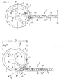
- Fig. 1 and Fig. 2 shown advantageous Schneidver confuser extruder combination for conditioning or recycling of plastic material has a circular cylindrical container or cutting compressor or breaker 1 with a flat, horizontal bottom surface 2 and a normally aligned, vertical, cylinder jacket-shaped side wall 9.
- the height of the side wall 9 - measured from the bottom surface 2 to the top edge of the side wall 9 - is a parallel to the bottom surface 2 aligned, planar support disk or a tool carrier 13, which is rotatable about a central axis of rotation 10, which is also the central center axis of the container 1, in the direction of rotation 12 marked with an arrow 12.
- the carrier disk 13 is driven by a motor 21 which is located below the container 1.
- knives or tools, e.g. Cutting knife, 14 are arranged, which together with the carrier plate 13, the mixing and / or crushing tool 3.
- the knives 14 are not arranged symmetrically on the support plate 13, but are particularly formed on their pointing in the direction of rotation or movement 12 front edges 22, employed or arranged to be able to act on the plastic material mechanically specific.
- the radially outermost edges of the mixing and crushing tools 3 extend to relatively close, about 5% of the radius 11 of the container 1, to the inner surface of the side wall 9 zoom.
- the container 1 has at the top an insertion opening, through which the material to be processed, for example portions of plastic films, eg by means of a conveyor in the direction of the arrow is thrown.
- the container 1 is closed and at least evacuated to a technical vacuum, wherein the material is introduced via a lock systems.
- This good is detected by the circulating mixing and / or crushing tools 3 and in the form of a Mischtrombe 30 swirled up, the good rises along the vertical side wall 9 and falls back almost in the range of the effective container height H by gravity back in and down in the area of the container center.
- the effective height H of the container 1 is approximately equal to its inner diameter D.
- the container 1 thus forms a Mischtrombe 30, in which the material is swirled both from top to bottom and in the direction of rotation 12.
- a Mischtrombe 30 in which the material is swirled both from top to bottom and in the direction of rotation 12.
- Such a device can thus due to the special arrangement of the mixing and crushing tools 3 and the blade 14 are operated only with the predetermined rotational or movement direction 12 and the direction of rotation 12 can not be made without further or without additional changes, are reversed.
- the introduced plastic material is comminuted by the circulating mixing and crushing tools 3, mixed and thereby heated by the introduced mechanical friction energy and softened, but not melted.
- the homogenized, softened, doughy but not molten material discharged through an opening 8 from the container 1, brought into the catchment area of an extruder 5 and there by a screw 6th recorded and subsequently melted.
- said opening 8 is formed in the side wall 9 of the container 1, through which the pretreated plastic material from the interior of the container 1 can be discharged.
- the material is transferred to a single-screw extruder 5 arranged tangentially on the container 1, the housing 16 of the extruder 5 having an intake opening 80 in its casing wall for the material to be detected by the screw 6.
- Such an embodiment has the advantage that the screw 6 can be driven by the lower front end in the drawing by a drive shown only schematically, so that the upper end of the screw 6 in the drawing can be kept free from the drive.
- the intake opening 80 communicates with the opening 8 in Material wise- or transfer connection and is connected in the present case directly, directly and without a longer intermediate piece or spacing with the opening 8. Only a very short transfer area is provided.
- a compressing screw 6 is rotatably supported about its longitudinal axis 15.
- the longitudinal axis 15 of the screw 6 and the extruder 5 coincide.
- the extruder 5 conveys the material in the direction of arrow 17.
- the extruder 5 is a conventional extruder known per se, in which the softened plastic material is compressed and thereby melted, and the melt then emerges on the opposite side of the extruder head.
- the mixing and / or comminution tools 3 or the knives 14 are located at almost the same height or plane as the central longitudinal axis 15 of the extruder 5. The outermost ends of the blades 14 are sufficiently spaced from the webs of the screw 6.
- Fig. 1 and 2 is the extruder 5, as mentioned, connected tangentially to the container 1 and extends tangentially to the cross section thereof.
- the longitudinal axis 15 of the extruder 5 or the screw 6 is on the outlet side to the longitudinal axis 15 parallel, from the axis of rotation 10 of the mixing and / or crushing tool 3 in the conveying direction 17 of the extruder 5 outwardly directed radials 11 of the container 1 by a distance 18 added.
- the rearward extension of the longitudinal axis 15 of the extruder 5 does not penetrate the interior of the container 1, but runs just past it.
- the distance 18 is slightly larger than the radius of the container 1.
- the extruder 5 is thus slightly offset from the outside or the catchment area is slightly deeper.
- opposite is meant here any alignment of the vectors to each other which is not acute-angled, as will be explained in detail below.
- the scalar product is a directional vector 19 of the direction of rotation 12, which is tangent to the flight circle of the outermost point of the mixing and / or crushing tool 3 or tangential to the plastic material passing past the opening 8 and the direction of rotation or movement 12 the mixing and / or crushing tools 3, and a direction vector 17 of the conveying direction of the extruder 5, which is parallel to the central longitudinal axis 15 in the conveying direction at each point of the opening 8 and in the region radially immediately in front of the opening 8, zero everywhere or negative, but nowhere positive.
- At the intake opening in Fig. 1 and 2 is the scalar product of the direction vector 19 of the direction of rotation 12 and the direction vector 17 of the conveying direction in each point of the opening 8 negative.
- the angle ⁇ between the directional vector 17 of the conveying direction and the directional vector of the direction of rotation 19, measured in the most upstream of the direction of rotation 12 point 20 of the opening 8 and at the most upstream edge of the opening 8, is almost maximum, about 170 ° ,
- angles ⁇ are no longer referred to as angles ⁇ , since they are not measured in point 20.
- An in Fig. 2 not shown, measured in the middle or in the center of the opening 8 angle ⁇ between the direction vector of the direction of rotation 19 and the direction vector of the conveying direction 17 is about 178 ° to 180 °.
- the device according to Fig. 2 represents the first limiting case or extreme value.
- a very gentle stuffing action or a particularly advantageous feeding is possible and such a device is particularly advantageous for sensitive materials that are processed near the melting area or for long-striped Good.
- Fig. 3 an alternative embodiment is shown, in which the extruder 5 is not connected tangentially, but with its end face 7 to the container 1.
- the screw 6 and the housing 16 of the extruder 5 are adapted in the region of the opening 8 to the contour of the inner wall of the container 1 and set back flush. No part of the extruder 5 protrudes through the opening 8 into the interior of the container 1.
- the distance 18 here corresponds to about 5 to 10% of the radius 11 of the container 1 and about half the inner diameter d of the housing 16. This constitutesfrom thus represents the second limiting case or extreme value with the smallest possible offset or distance 18, in which the rotary or the direction of movement 12 of the mixing and / or crushing tools 3 of the conveying direction 17 of the extruder 5 is at least slightly opposite, namely over the entire surface of the opening eighth
- the scalar product is in Fig. 3 in the borderline, furthest upstream, point 20 exactly zero, the furthest upstream located, edge 20 'of the opening 8 is located.
- the angle ⁇ between the direction vector 17 of the conveying direction and the direction vector of the direction of rotation 19 is measured in point 20 of FIG Fig. 3 , exactly 90 °. If one proceeds along the opening 8 downwards, ie in the direction of rotation 12, then the angle between the directional vectors becomes ever larger and at an obtuse angle> 90 ° and the scalar product simultaneously becomes negative. However, at no point or in any area of the opening 8 is the scale product positive or the angle less than 90 °. As a result, local overfeeding can not take place even in a partial region of the opening 8 or, in any region of the opening 8, there can be no harmful inflated tamping action.
- Fig. 4 a further alternative embodiment is shown in which the extruder 5 is slightly more offset on the outlet side than at Fig. 3 , but not tangential as in Fig. 1 and 2 .
- the extension of the longitudinal axis 15 of the extruder 5, which is intended to be rearward penetrates the interior of the container 1 in a secant manner.
- the distance 18 is correspondingly larger than at Fig. 3 , but slightly smaller than the radius 11.
- the angle ⁇ measured at point 20 is about 150 °, whereby compared to the device of Fig. 3 the stuffing effect is reduced, which is more advantageous for certain sensitive polymers.
- Seen from the container 1 from right inner edge or the inner wall of the housing 16 connects tangentially to the container 1, whereby, in contrast to Fig. 3 no blunt transition edge is formed.
- the stated constants allow the device to be adapted to different materials or feed compositions with different materials in order to avoid clogging and to increase the printing set.
- the container 1 is preferably designed as a cutting compressor, to which an extruder is completed as a conveyor.
- the diameter D is determined by the cross-sectional area of the container is converted to a circular area and the diameter of this circle is used as a container diameter.
- D is thus the inner diameter of a circular cylindrical container 1 in mm or the inner diameter in mm of the same volume of volume converted fictitious circular cylindrical container of the same height.
Landscapes
- Engineering & Computer Science (AREA)
- Mechanical Engineering (AREA)
- Food Science & Technology (AREA)
- Environmental & Geological Engineering (AREA)
- Chemical & Material Sciences (AREA)
- Chemical Kinetics & Catalysis (AREA)
- Life Sciences & Earth Sciences (AREA)
- Sustainable Development (AREA)
- Processing And Handling Of Plastics And Other Materials For Molding In General (AREA)
- Separation, Recovery Or Treatment Of Waste Materials Containing Plastics (AREA)
- Extrusion Moulding Of Plastics Or The Like (AREA)
Priority Applications (2)
| Application Number | Priority Date | Filing Date | Title |
|---|---|---|---|
| PL12781257T PL2766160T3 (pl) | 2011-10-14 | 2012-10-12 | Urządzenie do obróbki materiału z tworzywa sztucznego |
| SI201230490T SI2766160T1 (sl) | 2011-10-14 | 2012-10-12 | Naprava za pripravo materiala iz umetne snovi |
Applications Claiming Priority (2)
| Application Number | Priority Date | Filing Date | Title |
|---|---|---|---|
| ATA1510/2011A AT512222B1 (de) | 2011-10-14 | 2011-10-14 | Vorrichtung zum aufbereiten von kunststoffmaterial |
| PCT/AT2012/050153 WO2013052981A1 (de) | 2011-10-14 | 2012-10-12 | Vorrichtung zum aufbereiten von kunststoffmaterial |
Publications (2)
| Publication Number | Publication Date |
|---|---|
| EP2766160A1 EP2766160A1 (de) | 2014-08-20 |
| EP2766160B1 true EP2766160B1 (de) | 2015-12-16 |
Family
ID=47142836
Family Applications (1)
| Application Number | Title | Priority Date | Filing Date |
|---|---|---|---|
| EP12781257.6A Active EP2766160B1 (de) | 2011-10-14 | 2012-10-12 | Vorrichtung zum aufbereiten von kunststoffmaterial |
Country Status (23)
| Country | Link |
|---|---|
| US (1) | US11931946B2 (ja) |
| EP (1) | EP2766160B1 (ja) |
| JP (1) | JP6219829B2 (ja) |
| KR (1) | KR101744262B1 (ja) |
| CN (1) | CN103930248B (ja) |
| AT (1) | AT512222B1 (ja) |
| AU (1) | AU2012323810B2 (ja) |
| BR (1) | BR112014008813B1 (ja) |
| CA (1) | CA2851949C (ja) |
| DE (1) | DE202012012568U1 (ja) |
| DK (1) | DK2766160T3 (ja) |
| ES (1) | ES2561722T3 (ja) |
| HK (1) | HK1200762A1 (ja) |
| HU (1) | HUE026896T2 (ja) |
| MX (1) | MX345434B (ja) |
| PL (1) | PL2766160T3 (ja) |
| PT (1) | PT2766160E (ja) |
| RU (1) | RU2583260C2 (ja) |
| SI (1) | SI2766160T1 (ja) |
| TW (1) | TWI524977B (ja) |
| UA (1) | UA110147C2 (ja) |
| WO (1) | WO2013052981A1 (ja) |
| ZA (1) | ZA201402101B (ja) |
Families Citing this family (13)
| Publication number | Priority date | Publication date | Assignee | Title |
|---|---|---|---|---|
| AT504709B1 (de) * | 2006-11-23 | 2008-09-15 | Erema | Verfahren und vorrichtung zur einbringung von zusatzstoffen |
| AT511362B1 (de) | 2010-04-14 | 2014-01-15 | Erema | Vorrichtung zum aufbereiten von kunststoffmaterial |
| AT512149B1 (de) | 2011-10-14 | 2015-02-15 | Erema | Vorrichtung zum aufbereiten von kunststoffmaterial |
| AT512205B1 (de) | 2011-10-14 | 2015-02-15 | Erema | Vorrichtung zum aufbereiten von kunststoffmaterial |
| AT512212B1 (de) | 2011-10-14 | 2015-02-15 | Erema | Vorrichtung zum aufbereiten von kunststoffmaterial |
| AT512209B1 (de) | 2011-10-14 | 2015-02-15 | Erema | Vorrichtung zum aufbereiten von kunststoffmaterial |
| AT512208B1 (de) * | 2011-10-14 | 2015-02-15 | Erema | Vorrichtung zum aufbereiten von kunststoffmaterial |
| AT512145B1 (de) | 2011-10-14 | 2015-02-15 | Erema | Vorrichtung zum aufbereiten von kunststoffmaterial |
| AT512223B1 (de) | 2011-10-14 | 2015-02-15 | Erema | Vorrichtung zum aufbereiten von kunststoffmaterial |
| AT512146B1 (de) | 2011-10-14 | 2015-02-15 | Erema | Vorrichtung zum aufbereiten von kunststoffmaterial |
| AT512148B1 (de) | 2011-10-14 | 2015-02-15 | Erema | Vorrichtung zum aufbereiten von kunststoffmaterial |
| AT512207B1 (de) | 2011-10-14 | 2015-02-15 | Erema | Vorrichtung zum aufbereiten von kunststoffmaterial |
| AT515363B1 (de) * | 2014-01-28 | 2018-12-15 | Erema Eng Recycling Maschinen & Anlagen Gmbh | Zerkleinerungswerkzeug |
Family Cites Families (66)
| Publication number | Priority date | Publication date | Assignee | Title |
|---|---|---|---|---|
| US2927007A (en) | 1957-04-17 | 1960-03-01 | Braunschweigische Maschb Ansta | Apparatus for the treatment of animal and vegetable materials |
| DE2224209C3 (de) | 1972-05-18 | 1982-12-30 | Buckau-Walther AG, 4048 Grevenbroich | Vorrichtung zum Auswerfen der trockenen, ausgelaugten Schnitzel aus einem Diffusionsturm |
| SU536062A1 (ru) | 1974-01-04 | 1976-11-25 | Научно-Исследовательский Конструкторско-Технологический Институт Шинной Промышленности | Устройство дл измельчени эластичных полимерных материалов |
| AT354076B (de) * | 1978-03-02 | 1979-12-27 | Krauss Maffei Austria | Vorrichtung zum aufbereiten von thermo- plastischem kunststoffgut, wie folien, hohl- koerper, splitter od.dgl. |
| DE2839446C2 (de) | 1978-09-11 | 1980-09-25 | Thyssen Industrie Ag, 4300 Essen | Vorrichtung zum Verdichten und Agglomerieren von Kunststoffabfällen |
| AT368737B (de) | 1980-07-31 | 1982-11-10 | Oesterr Schiffswerften | Vorrichtung zum aufbereiten von thermoplastischem kunststoffgut |
| DE3231237A1 (de) | 1982-08-23 | 1984-02-23 | Dr. Herfeld GmbH & Co KG, 5982 Neuenrade | Verfahren zum verdichten von thermoplastischem kunststoffmaterial |
| AT375867B (de) | 1983-04-27 | 1984-09-25 | Erema | Vorrichtung zum aufbereiten von thermoplastischem kunststoffgut |
| GB2145351A (en) | 1983-08-24 | 1985-03-27 | Howden James & Co Ltd | Pulverizer |
| AT385234B (de) | 1984-08-01 | 1988-03-10 | Paracon Extrusionstech Gmbh | Vorrichtung zum aufbereiten von thermoplastischem kunststoffgut |
| AT387747B (de) | 1986-10-10 | 1989-03-10 | Erema | Vorrichtung zum aufbereiten von kunststoffgut |
| CH673105A5 (ja) | 1987-08-18 | 1990-02-15 | Indupack Ag | |
| DE8716077U1 (ja) | 1987-12-04 | 1988-02-11 | Plastmachines Gelderland, 8039 Puchheim, De | |
| JPH07112708B2 (ja) | 1991-05-02 | 1995-12-06 | ワイケイケイ株式会社 | 射出成形機における着色成形材料の自動変換供給装置 |
| AT398772B (de) | 1992-04-30 | 1995-01-25 | Erema | Verfahren und vorrichtung zum recycling von begastem kunststoffmaterial |
| AT400315B (de) | 1994-03-01 | 1995-12-27 | Bacher Helmut | Vorrichtung zum entgasen von thermoplastischem kunststoff |
| ES2094657T3 (es) | 1993-06-08 | 1997-01-16 | Helmut Bacher | Dispositivo para desgasificar material termoplastico. |
| JPH07148736A (ja) | 1993-11-30 | 1995-06-13 | Tomomichi Uchida | 射出成型機よりの廃プラ材の折断装置 |
| US5783225A (en) * | 1993-12-21 | 1998-07-21 | Bacher; Helmut | Apparatus for processing thermoplastic synthetic plastics material |
| ES2102912T3 (es) * | 1993-12-21 | 1997-08-01 | Helmut Bacher | Dispositivo de tratamiento de materias termoplasticas. |
| AT405726B (de) | 1995-04-11 | 1999-11-25 | Bacher Helmut | Vorrichtung zum aufbereiten thermoplastischen kunststoffgutes |
| ES2147940T3 (es) | 1995-11-11 | 2000-10-01 | Schafer Elektrotechnik Sonderm | Procedimiento para procesar elementos de construccion de materiales sinteticos mixtos y otros materiales de construccion mezclados con ellos, y dispositivo para realizar el procedimiento. |
| JPH1142641A (ja) * | 1997-07-29 | 1999-02-16 | Sugihara Hosei Kogyo Kk | 廃プラスチックの再生法および再生品 |
| IT1295628B1 (it) | 1997-10-17 | 1999-05-24 | Gamma Meccanica Srl | Apparecchiatura per l'alimentazione di un estrusore a coclea con materiale plastico sminuzzato. |
| AT407235B (de) | 1999-04-23 | 2001-01-25 | Bacher Helmut | Vorrichtung zum kontinuierlichen recyclen von kunststoffmaterial, vorzugsweise polyester |
| AT407970B (de) * | 1999-06-02 | 2001-07-25 | Bacher Helmut | Vorrichtung und verfahren zum aufbereiten von, insbesondere thermoplastischem, kunststoffmaterial |
| JP2001026019A (ja) | 1999-07-14 | 2001-01-30 | Sintokogio Ltd | 廃プラスチックの塗料除去装置における温度制御方法および廃プラスチックの塗料除去装置。 |
| JP4073580B2 (ja) | 1999-07-19 | 2008-04-09 | 新東工業株式会社 | 塗膜付き樹脂部品の再生処理装置 |
| AT411161B (de) | 1999-09-22 | 2003-10-27 | Bacher Helmut | Verfahren und vorrichtung zum recyclen von pet-gut |
| AT407972B (de) * | 1999-12-02 | 2001-07-25 | Bacher Helmut | Vorrichtung zum vorbehandeln und anschliessenden plastifizieren oder agglomerieren von kunststoffen |
| AT412623B (de) | 2000-04-26 | 2005-05-25 | Bacher Helmut | Vorrichtung und verfahren zum aufbereiten von thermoplastischem kunststoffgut |
| US20020125600A1 (en) | 2000-10-31 | 2002-09-12 | David Horne | Plastic recycling system and process |
| AT410298B (de) | 2001-06-11 | 2003-03-25 | Bacher Helmut | Vorrichtung zur befüllung einer in einem gehäuse gelagerten schnecke und verfahren zum betrieb einer solchen vorrichtung |
| EP1273412A1 (en) | 2001-07-02 | 2003-01-08 | Magma Trade di Mauro Magni & C.snc | Process and apparatus for the production of filled thermoplastic polymers |
| DE10140215A1 (de) | 2001-08-16 | 2003-02-27 | Novum 2000 Gmbh | Vorrichtung zur Aufbereitung von Kunststoffen |
| AT411235B (de) | 2002-06-05 | 2003-11-25 | Bacher Helmut | Vorrichtung zur aufbereitung von thermoplastischem kunststoffmaterial |
| AT411038B (de) | 2002-06-10 | 2003-09-25 | Bacher Helmut | Vorrichtung zur behandlung von kunststoffgut |
| AT503334B1 (de) | 2003-04-01 | 2010-06-15 | Erema | Verfahren und vorrichtung zur plastifizierung von kunststoffmaterial |
| AT413512B (de) * | 2003-06-05 | 2006-03-15 | Helmut Bacher | Vorrichtung zur aufbereitung von kunststoffmaterial zu recyclingzwecken |
| AT413511B (de) * | 2003-06-05 | 2006-03-15 | Bacher Helmut | Vorrichtung zur aufbereitung von kunststoffmaterial zu recyclingzwecken |
| AT413199B (de) | 2004-03-17 | 2005-12-15 | Erema | Vorrichtung zum aufbereiten von kunststoffmaterial |
| AT413673B (de) | 2004-07-16 | 2006-04-15 | Erema | Vorrichtung und verfahren zur aufbereitung von thermoplastischem, zu recycelndem kunststoffmaterial |
| US20070102550A1 (en) | 2005-11-07 | 2007-05-10 | Lin Ping H | Plastic grain cutting and transporting mechanism |
| AT503014B1 (de) | 2006-04-27 | 2007-07-15 | Schulz Helmuth | Vorrichtung zum extrudieren von thermoplastischem kunststoffgut |
| AT504326B8 (de) | 2006-10-30 | 2008-09-15 | Next Generation Recyclingmasch | Vorrichtung zum aufbereiten von thermoplastischem kunststoffmaterial |
| AT504709B1 (de) | 2006-11-23 | 2008-09-15 | Erema | Verfahren und vorrichtung zur einbringung von zusatzstoffen |
| AT504854B1 (de) | 2007-02-15 | 2012-08-15 | Erema | Verfahren und vorrichtung zur aufbereitung eines materials |
| AT505595B1 (de) | 2007-08-14 | 2009-04-15 | Erema | Verfahren und vorrichtung zur behandlung von kunststoffmaterial |
| AT506489B1 (de) | 2008-02-14 | 2010-12-15 | Erema | Verfahren und vorrichtung zum spritzgiessen von kunststoffmaterial |
| AT508951B1 (de) | 2009-04-17 | 2012-03-15 | Erema | Verfahren und anordnung zur recyclierung von kunststoff |
| AT11398U1 (de) | 2009-08-20 | 2010-10-15 | Engel Austria Gmbh | 3-zonen-plastifizierschnecke mit mischteil |
| EP2316562A1 (de) | 2009-10-29 | 2011-05-04 | Bühler AG | Vorrichtung und Verfahren zur Behandlung eines Schüttguts |
| AT511362B1 (de) | 2010-04-14 | 2014-01-15 | Erema | Vorrichtung zum aufbereiten von kunststoffmaterial |
| AT509323B1 (de) | 2010-04-16 | 2011-08-15 | Erema | Verfahren und vorrichtung zur aufbereitung und reinigung eines polymermaterials |
| RU98971U1 (ru) * | 2010-06-01 | 2010-11-10 | Государственное образовательное учреждение высшего профессионального образования "Дальневосточный государственный технический университет (ДВПИ имени В.В. Куйбышева)" | Устройство для переработки термопластов |
| AT512146B1 (de) | 2011-10-14 | 2015-02-15 | Erema | Vorrichtung zum aufbereiten von kunststoffmaterial |
| AT512205B1 (de) | 2011-10-14 | 2015-02-15 | Erema | Vorrichtung zum aufbereiten von kunststoffmaterial |
| AT512212B1 (de) | 2011-10-14 | 2015-02-15 | Erema | Vorrichtung zum aufbereiten von kunststoffmaterial |
| AT512147B1 (de) | 2011-10-14 | 2015-02-15 | Erema | Vorrichtung zum aufbereiten von kunststoffmaterial |
| AT512207B1 (de) | 2011-10-14 | 2015-02-15 | Erema | Vorrichtung zum aufbereiten von kunststoffmaterial |
| AT512223B1 (de) | 2011-10-14 | 2015-02-15 | Erema | Vorrichtung zum aufbereiten von kunststoffmaterial |
| AT512209B1 (de) | 2011-10-14 | 2015-02-15 | Erema | Vorrichtung zum aufbereiten von kunststoffmaterial |
| AT512145B1 (de) | 2011-10-14 | 2015-02-15 | Erema | Vorrichtung zum aufbereiten von kunststoffmaterial |
| AT512208B1 (de) | 2011-10-14 | 2015-02-15 | Erema | Vorrichtung zum aufbereiten von kunststoffmaterial |
| AT512149B1 (de) | 2011-10-14 | 2015-02-15 | Erema | Vorrichtung zum aufbereiten von kunststoffmaterial |
| AT512148B1 (de) | 2011-10-14 | 2015-02-15 | Erema | Vorrichtung zum aufbereiten von kunststoffmaterial |
-
2011
- 2011-10-14 AT ATA1510/2011A patent/AT512222B1/de active
-
2012
- 2012-10-12 WO PCT/AT2012/050153 patent/WO2013052981A1/de active Application Filing
- 2012-10-12 RU RU2014119375/05A patent/RU2583260C2/ru active
- 2012-10-12 TW TW101137663A patent/TWI524977B/zh active
- 2012-10-12 EP EP12781257.6A patent/EP2766160B1/de active Active
- 2012-10-12 BR BR112014008813-6A patent/BR112014008813B1/pt active IP Right Grant
- 2012-10-12 SI SI201230490T patent/SI2766160T1/sl unknown
- 2012-10-12 KR KR1020147013026A patent/KR101744262B1/ko active IP Right Grant
- 2012-10-12 CN CN201280050416.3A patent/CN103930248B/zh active Active
- 2012-10-12 US US14/351,869 patent/US11931946B2/en active Active
- 2012-10-12 HU HUE12781257A patent/HUE026896T2/en unknown
- 2012-10-12 DE DE201220012568 patent/DE202012012568U1/de not_active Expired - Lifetime
- 2012-10-12 DK DK12781257.6T patent/DK2766160T3/en active
- 2012-10-12 MX MX2014004447A patent/MX345434B/es active IP Right Grant
- 2012-10-12 ES ES12781257.6T patent/ES2561722T3/es active Active
- 2012-10-12 AU AU2012323810A patent/AU2012323810B2/en active Active
- 2012-10-12 CA CA2851949A patent/CA2851949C/en active Active
- 2012-10-12 JP JP2014534873A patent/JP6219829B2/ja active Active
- 2012-10-12 PT PT127812576T patent/PT2766160E/pt unknown
- 2012-10-12 PL PL12781257T patent/PL2766160T3/pl unknown
- 2012-12-10 UA UAA201403663A patent/UA110147C2/ru unknown
-
2014
- 2014-03-20 ZA ZA2014/02101A patent/ZA201402101B/en unknown
-
2015
- 2015-02-06 HK HK15101320.2A patent/HK1200762A1/zh unknown
Also Published As
Similar Documents
| Publication | Publication Date | Title |
|---|---|---|
| EP2766160B1 (de) | Vorrichtung zum aufbereiten von kunststoffmaterial | |
| EP2766165B1 (de) | Vorrichtung zum aufbereiten von kunststoffmaterial | |
| EP2766167B1 (de) | Vorrichtung zum aufbereiten von kunststoffmaterial | |
| EP2766162B1 (de) | Vorrichtung zum aufbereiten von kunststoffmaterial | |
| EP2768645B1 (de) | Vorrichtung zum aufbereiten von kunststoffmaterial | |
| EP2766159B1 (de) | Vorrichtung zum aufbereiten von kunststoffmaterial | |
| EP2766166B1 (de) | Vorrichtung zum aufbereiten von kunststoffmaterial | |
| EP2766157B1 (de) | Vorrichtung zum aufbereiten von kunststoffmaterial | |
| EP2766164B1 (de) | Vorrichtung zum aufbereiten von kunststoffmaterial | |
| EP2766158B1 (de) | Vorrichtung zum aufbereiten von kunststoffmaterial | |
| EP2766161B1 (de) | Vorrichtung zum aufbereiten von kunststoffmaterial |
Legal Events
| Date | Code | Title | Description |
|---|---|---|---|
| PUAI | Public reference made under article 153(3) epc to a published international application that has entered the european phase |
Free format text: ORIGINAL CODE: 0009012 |
|
| 17P | Request for examination filed |
Effective date: 20140514 |
|
| AK | Designated contracting states |
Kind code of ref document: A1 Designated state(s): AL AT BE BG CH CY CZ DE DK EE ES FI FR GB GR HR HU IE IS IT LI LT LU LV MC MK MT NL NO PL PT RO RS SE SI SK SM TR |
|
| DAX | Request for extension of the european patent (deleted) | ||
| GRAP | Despatch of communication of intention to grant a patent |
Free format text: ORIGINAL CODE: EPIDOSNIGR1 |
|
| RIC1 | Information provided on ipc code assigned before grant |
Ipc: B29C 47/00 20060101ALI20150513BHEP Ipc: B02C 18/22 20060101ALI20150513BHEP Ipc: B01F 15/02 20060101ALI20150513BHEP Ipc: B29C 47/40 20060101ALN20150513BHEP Ipc: B29B 17/04 20060101ALI20150513BHEP Ipc: B29C 47/10 20060101ALI20150513BHEP Ipc: B29B 13/10 20060101AFI20150513BHEP Ipc: B29B 7/66 20060101ALI20150513BHEP Ipc: B29K 105/26 20060101ALN20150513BHEP Ipc: B29C 47/58 20060101ALN20150513BHEP Ipc: B29C 47/38 20060101ALI20150513BHEP Ipc: B02C 18/08 20060101ALI20150513BHEP |
|
| INTG | Intention to grant announced |
Effective date: 20150601 |
|
| RIC1 | Information provided on ipc code assigned before grant |
Ipc: B29C 47/38 20060101ALI20150515BHEP Ipc: B29B 17/04 20060101ALI20150515BHEP Ipc: B29C 47/00 20060101ALI20150515BHEP Ipc: B29C 47/10 20060101ALI20150515BHEP Ipc: B02C 18/22 20060101ALI20150515BHEP Ipc: B29C 47/40 20060101ALN20150515BHEP Ipc: B29K 105/26 20060101ALN20150515BHEP Ipc: B29B 7/66 20060101ALI20150515BHEP Ipc: B29C 47/58 20060101ALN20150515BHEP Ipc: B01F 15/02 20060101ALI20150515BHEP Ipc: B02C 18/08 20060101ALI20150515BHEP Ipc: B29B 13/10 20060101AFI20150515BHEP |
|
| REG | Reference to a national code |
Ref country code: HK Ref legal event code: DE Ref document number: 1200762 Country of ref document: HK |
|
| GRAS | Grant fee paid |
Free format text: ORIGINAL CODE: EPIDOSNIGR3 |
|
| GRAA | (expected) grant |
Free format text: ORIGINAL CODE: 0009210 |
|
| AK | Designated contracting states |
Kind code of ref document: B1 Designated state(s): AL AT BE BG CH CY CZ DE DK EE ES FI FR GB GR HR HU IE IS IT LI LT LU LV MC MK MT NL NO PL PT RO RS SE SI SK SM TR |
|
| REG | Reference to a national code |
Ref country code: GB Ref legal event code: FG4D Free format text: NOT ENGLISH |
|
| REG | Reference to a national code |
Ref country code: CH Ref legal event code: EP |
|
| REG | Reference to a national code |
Ref country code: IE Ref legal event code: FG4D Free format text: LANGUAGE OF EP DOCUMENT: GERMAN |
|
| REG | Reference to a national code |
Ref country code: AT Ref legal event code: REF Ref document number: 765325 Country of ref document: AT Kind code of ref document: T Effective date: 20160115 |
|
| REG | Reference to a national code |
Ref country code: DE Ref legal event code: R096 Ref document number: 502012005526 Country of ref document: DE |
|
| REG | Reference to a national code |
Ref country code: CH Ref legal event code: NV Representative=s name: PATWIL AG, CH |
|
| REG | Reference to a national code |
Ref country code: ES Ref legal event code: FG2A Ref document number: 2561722 Country of ref document: ES Kind code of ref document: T3 Effective date: 20160229 |
|
| REG | Reference to a national code |
Ref country code: SE Ref legal event code: TRGR |
|
| REG | Reference to a national code |
Ref country code: NL Ref legal event code: FP |
|
| REG | Reference to a national code |
Ref country code: RO Ref legal event code: EPE |
|
| REG | Reference to a national code |
Ref country code: DK Ref legal event code: T3 Effective date: 20160311 |
|
| REG | Reference to a national code |
Ref country code: PT Ref legal event code: SC4A Free format text: AVAILABILITY OF NATIONAL TRANSLATION Effective date: 20160223 |
|
| REG | Reference to a national code |
Ref country code: LT Ref legal event code: MG4D |
|
| PG25 | Lapsed in a contracting state [announced via postgrant information from national office to epo] |
Ref country code: NO Free format text: LAPSE BECAUSE OF FAILURE TO SUBMIT A TRANSLATION OF THE DESCRIPTION OR TO PAY THE FEE WITHIN THE PRESCRIBED TIME-LIMIT Effective date: 20160316 Ref country code: LT Free format text: LAPSE BECAUSE OF FAILURE TO SUBMIT A TRANSLATION OF THE DESCRIPTION OR TO PAY THE FEE WITHIN THE PRESCRIBED TIME-LIMIT Effective date: 20151216 Ref country code: HR Free format text: LAPSE BECAUSE OF FAILURE TO SUBMIT A TRANSLATION OF THE DESCRIPTION OR TO PAY THE FEE WITHIN THE PRESCRIBED TIME-LIMIT Effective date: 20151216 |
|
| PG25 | Lapsed in a contracting state [announced via postgrant information from national office to epo] |
Ref country code: FI Free format text: LAPSE BECAUSE OF FAILURE TO SUBMIT A TRANSLATION OF THE DESCRIPTION OR TO PAY THE FEE WITHIN THE PRESCRIBED TIME-LIMIT Effective date: 20151216 Ref country code: LV Free format text: LAPSE BECAUSE OF FAILURE TO SUBMIT A TRANSLATION OF THE DESCRIPTION OR TO PAY THE FEE WITHIN THE PRESCRIBED TIME-LIMIT Effective date: 20151216 Ref country code: GR Free format text: LAPSE BECAUSE OF FAILURE TO SUBMIT A TRANSLATION OF THE DESCRIPTION OR TO PAY THE FEE WITHIN THE PRESCRIBED TIME-LIMIT Effective date: 20160317 Ref country code: RS Free format text: LAPSE BECAUSE OF FAILURE TO SUBMIT A TRANSLATION OF THE DESCRIPTION OR TO PAY THE FEE WITHIN THE PRESCRIBED TIME-LIMIT Effective date: 20151216 |
|
| REG | Reference to a national code |
Ref country code: SK Ref legal event code: T3 Ref document number: E 20546 Country of ref document: SK |
|
| REG | Reference to a national code |
Ref country code: HK Ref legal event code: GR Ref document number: 1200762 Country of ref document: HK |
|
| REG | Reference to a national code |
Ref country code: HU Ref legal event code: AG4A Ref document number: E026896 Country of ref document: HU |
|
| PG25 | Lapsed in a contracting state [announced via postgrant information from national office to epo] |
Ref country code: IS Free format text: LAPSE BECAUSE OF FAILURE TO SUBMIT A TRANSLATION OF THE DESCRIPTION OR TO PAY THE FEE WITHIN THE PRESCRIBED TIME-LIMIT Effective date: 20160416 Ref country code: EE Free format text: LAPSE BECAUSE OF FAILURE TO SUBMIT A TRANSLATION OF THE DESCRIPTION OR TO PAY THE FEE WITHIN THE PRESCRIBED TIME-LIMIT Effective date: 20151216 Ref country code: SM Free format text: LAPSE BECAUSE OF FAILURE TO SUBMIT A TRANSLATION OF THE DESCRIPTION OR TO PAY THE FEE WITHIN THE PRESCRIBED TIME-LIMIT Effective date: 20151216 |
|
| REG | Reference to a national code |
Ref country code: DE Ref legal event code: R097 Ref document number: 502012005526 Country of ref document: DE |
|
| REG | Reference to a national code |
Ref country code: FR Ref legal event code: PLFP Year of fee payment: 5 |
|
| PLBE | No opposition filed within time limit |
Free format text: ORIGINAL CODE: 0009261 |
|
| STAA | Information on the status of an ep patent application or granted ep patent |
Free format text: STATUS: NO OPPOSITION FILED WITHIN TIME LIMIT |
|
| 26N | No opposition filed |
Effective date: 20160919 |
|
| REG | Reference to a national code |
Ref country code: IE Ref legal event code: MM4A |
|
| REG | Reference to a national code |
Ref country code: FR Ref legal event code: PLFP Year of fee payment: 6 |
|
| PG25 | Lapsed in a contracting state [announced via postgrant information from national office to epo] |
Ref country code: IE Free format text: LAPSE BECAUSE OF NON-PAYMENT OF DUE FEES Effective date: 20161012 |
|
| REG | Reference to a national code |
Ref country code: HU Ref legal event code: HC9C |
|
| REG | Reference to a national code |
Ref country code: CH Ref legal event code: NV Representative=s name: KAMINSKI HARMANN PATENTANWAELTE AG, CH |
|
| PG25 | Lapsed in a contracting state [announced via postgrant information from national office to epo] |
Ref country code: MT Free format text: LAPSE BECAUSE OF FAILURE TO SUBMIT A TRANSLATION OF THE DESCRIPTION OR TO PAY THE FEE WITHIN THE PRESCRIBED TIME-LIMIT Effective date: 20151216 Ref country code: MC Free format text: LAPSE BECAUSE OF FAILURE TO SUBMIT A TRANSLATION OF THE DESCRIPTION OR TO PAY THE FEE WITHIN THE PRESCRIBED TIME-LIMIT Effective date: 20151216 Ref country code: CY Free format text: LAPSE BECAUSE OF FAILURE TO SUBMIT A TRANSLATION OF THE DESCRIPTION OR TO PAY THE FEE WITHIN THE PRESCRIBED TIME-LIMIT Effective date: 20151216 Ref country code: MK Free format text: LAPSE BECAUSE OF FAILURE TO SUBMIT A TRANSLATION OF THE DESCRIPTION OR TO PAY THE FEE WITHIN THE PRESCRIBED TIME-LIMIT Effective date: 20151216 |
|
| REG | Reference to a national code |
Ref country code: FR Ref legal event code: PLFP Year of fee payment: 7 |
|
| PG25 | Lapsed in a contracting state [announced via postgrant information from national office to epo] |
Ref country code: AL Free format text: LAPSE BECAUSE OF FAILURE TO SUBMIT A TRANSLATION OF THE DESCRIPTION OR TO PAY THE FEE WITHIN THE PRESCRIBED TIME-LIMIT Effective date: 20151216 |
|
| REG | Reference to a national code |
Ref country code: DE Ref legal event code: R082 Ref document number: 502012005526 Country of ref document: DE Representative=s name: MUELLER, THOMAS, DIPL.-ING., DE |
|
| P01 | Opt-out of the competence of the unified patent court (upc) registered |
Effective date: 20230531 |
|
| PGFP | Annual fee paid to national office [announced via postgrant information from national office to epo] |
Ref country code: PT Payment date: 20230928 Year of fee payment: 12 Ref country code: PL Payment date: 20230928 Year of fee payment: 12 Ref country code: NL Payment date: 20231019 Year of fee payment: 12 |
|
| PGFP | Annual fee paid to national office [announced via postgrant information from national office to epo] |
Ref country code: LU Payment date: 20231019 Year of fee payment: 12 |
|
| PGFP | Annual fee paid to national office [announced via postgrant information from national office to epo] |
Ref country code: SK Payment date: 20231005 Year of fee payment: 12 |
|
| PGFP | Annual fee paid to national office [announced via postgrant information from national office to epo] |
Ref country code: GB Payment date: 20231020 Year of fee payment: 12 |
|
| PGFP | Annual fee paid to national office [announced via postgrant information from national office to epo] |
Ref country code: ES Payment date: 20231227 Year of fee payment: 12 |
|
| PGFP | Annual fee paid to national office [announced via postgrant information from national office to epo] |
Ref country code: TR Payment date: 20231009 Year of fee payment: 12 Ref country code: SI Payment date: 20230928 Year of fee payment: 12 Ref country code: SE Payment date: 20231019 Year of fee payment: 12 Ref country code: RO Payment date: 20231003 Year of fee payment: 12 Ref country code: IT Payment date: 20231026 Year of fee payment: 12 Ref country code: HU Payment date: 20231024 Year of fee payment: 12 Ref country code: FR Payment date: 20231025 Year of fee payment: 12 Ref country code: DK Payment date: 20231024 Year of fee payment: 12 Ref country code: DE Payment date: 20231020 Year of fee payment: 12 Ref country code: CZ Payment date: 20231004 Year of fee payment: 12 Ref country code: CH Payment date: 20231102 Year of fee payment: 12 Ref country code: BG Payment date: 20231020 Year of fee payment: 12 Ref country code: AT Payment date: 20231009 Year of fee payment: 12 |
|
| PGFP | Annual fee paid to national office [announced via postgrant information from national office to epo] |
Ref country code: BE Payment date: 20231019 Year of fee payment: 12 |