EP2762633B1 - Trockenschrank mit einer Türdichtung - Google Patents
Trockenschrank mit einer Türdichtung Download PDFInfo
- Publication number
- EP2762633B1 EP2762633B1 EP13000508.5A EP13000508A EP2762633B1 EP 2762633 B1 EP2762633 B1 EP 2762633B1 EP 13000508 A EP13000508 A EP 13000508A EP 2762633 B1 EP2762633 B1 EP 2762633B1
- Authority
- EP
- European Patent Office
- Prior art keywords
- door
- drying cabinet
- door seal
- sealing body
- wall
- Prior art date
- Legal status (The legal status is an assumption and is not a legal conclusion. Google has not performed a legal analysis and makes no representation as to the accuracy of the status listed.)
- Active
Links
Images

Classifications
-
- D—TEXTILES; PAPER
- D06—TREATMENT OF TEXTILES OR THE LIKE; LAUNDERING; FLEXIBLE MATERIALS NOT OTHERWISE PROVIDED FOR
- D06F—LAUNDERING, DRYING, IRONING, PRESSING OR FOLDING TEXTILE ARTICLES
- D06F58/00—Domestic laundry dryers
- D06F58/10—Drying cabinets or drying chambers having heating or ventilating means
Definitions
- the invention relates to a drying cabinet according to the preamble of the independent claim.
- the drying oven is in particular a drying oven for laundry.
- a device of this kind is in FR 1589565 disclosed. It has a door seal, not shown.
- the temperature in the interior of dry cabinets is usually above the ambient temperature. Furthermore, there is typically a high humidity in the interior of a drying cabinet. This leads to condensation on the cooler inner walls of the drying cabinet, in particular also on the inner wall of the door. The condensation is usually collected at the bottom of the drying cabinet.
- a door seal which serves to prevent the escape of temperature and humidity during operation of the drying cabinet.
- a door seal is known, which is fixed to the bottom of the drying cabinet and projects upwards in the direction of the door.
- this door seal has the disadvantage that it interferes with the loading and unloading of the drying cabinet and the storage area on the bottom of the drying cabinet -. for laundry baskets - diminished.
- the door seal of the drying cabinet comprises an elastically deformable sealing body having a stop surface for a bottom of a drying cabinet and a mounting surface for fixing the door seal to an inner wall of a door of the drying cabinet.
- an obliquely upwardly extending drainage surface for condensed water which forms (among other things) an upper side of the sealing body.
- the drainage surface projects laterally beyond the stop surface or its upper edge, while maintaining its oblique course.
- the upper edge of the abutment surface is defined as the uppermost point of the abutment surface which is in contact with the bottom of the drying cabinet in the state of the door seal mounted in a drying cabinet and when the door is closed.
- the drainage surface also protrudes laterally beyond the attachment surface or its upper edge while maintaining its oblique course.
- the drainage surface has a smooth surface, so that no water can collect on it.
- the material for the door seal for example, one or more elastomers can be used.
- the door seal according to the invention is at a lower Fixed edge of the inner wall of the door of the drying cabinet and indeed in such a height or that the stop surface of the door seal with the door closed sealingly against a bottom of the drying cabinet or on a parallel to the inner wall of the door front wall of the bottom, the drainage surface higher as the floor is arranged and (partially) protrudes over this.
- the door seal can be configured circumferentially. The drainage surface thus protrudes on one side into the interior of the drying cabinet.
- the drainage surface preferably at least partially has a curved inwardly with respect to the sealing body course.
- the curvature is preferably formed such that condensation water can not collect on the drainage surface, but expires from the drainage surface to the top of the drying cabinet floor.
- the door seal Since the door seal is to be attached to the inner wall of the door, the door seal does not hinder the loading and unloading of the drying cabinet nor does it limit the footprint formed by the bottom of the drying cabinet.
- the stop surface preferably extends obliquely, so that the sealing body tapers away from the drainage surface.
- the attachment surface runs parallel to the inner wall of the door, to which it is preferably fastened with an adhesive, for example a double-sided adhesive tape.
- the drainage area lies above the mounting surface on the door inner wall and thus covers the adhesive.
- a recess may be provided through which a compressible cavity is formed in the sealing body, so that the sealing body is formed similar to a bellows.
- a sealing lip is preferably provided at a lower edge between the mounting surface and the underside of the seal body, which obliquely downward and opposite to the stop surface protrudes from the sealing body and rests in the attached state on the inner door wall.
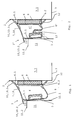
- FIG. 1 shows a door seal 1 according to the invention, which on an inner wall 2 of a door 3 of a drying cabinet 20 for laundry (see FIG. 4 ) is arranged.
- the door seal 1 is fixed in a lower portion 3.1 of the door 3.
- the door seal 1 is configured circumferentially and attached to the entire door 3 on the inner wall, the door seal 1, however, must be provided only in the lower area 3.1 with the drainage surface 10 described below.
- the door seal 1 has an elastic, deformable sealing body 4 with a stop surface 5, a stop surface 5 opposite mounting surface 6, a top 7 and a bottom 8.
- the attachment surface 6 is attached to the inner wall 2 of the door 3 via an adhesive 9, for example a double-sided adhesive strip.
- the stop surface 5 is connected via a lateral connecting surface 15 with the upper side 7.
- the upper edge 6.1 of the mounting surface 6 is above or higher than the upper edge 5.1 of the stop surface 5.
- As the upper edge 5.1 of the stop surface 5 is the uppermost point of the stop surface 5 defined in the closed state of the door 3 and the drying cabinet 20 whose bottom 11 contacted.
- the upper side 7 of the sealing body 4 extends obliquely upward toward the door 3, for which purpose the lateral connecting surface 15 is designed to be correspondingly short or correspondingly.
- the sealing body 4 has in cross section the shape of a parallelogram as in FIG. 1 shown.
- the upper side 7 of the sealing body 4 is formed by a correspondingly the course of the top 7 obliquely upwardly extending drainage surface 10 for condensed water in a substantially horizontal direction while maintaining its oblique course on one side on the stop surface 5 and on the other side over the attachment surface 6 (or the upper edges 5.1, 6.1) protrudes.
- the section 10.1 of the drainage surface 10 protruding beyond the fastening surface 6 abuts against the inner wall 2 of the door 3 and above the adhesive 9.
- the upper edge 5.1 is preferably so via the lateral connecting surface 15 of the sealing body 4 with its surface 7 (and thus connected to the drainage surface 10), that the portion 10.2 of the drainage surface 10 projects laterally from the sealing body 4 or protrudes.
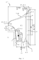
- the door seal 1 is attached to the inner wall 2 of the door 3 in such a height that the sealing body 4 of the door seal 1 strikes the floor 3 of the drying cabinet 20 or the front wall 11. 1 of the floor 11 when closing the door 3 is pressed, wherein the portion 10.2 of the drainage surface 10, which extends beyond the upper edge 5.1 of the stop surface 5 also extends above the bottom 11 and a top 11.2 of the bottom 11, ie in the lateral direction over the top 11.2 of the bottom 11 extends. When the door 3 is closed, therefore, the section 10.2 of the drainage surface 10 projects into the interior 21 of the drying cabinet 20 (see FIG FIG. 4 ).
- the stop surface 5 preferably extends inclined to the front wall 11.1 of the bottom 11, so that the sealing body 4 tapers from the top 7 to the bottom 8. For better adhesion to the front wall 11.1 of the bottom 11, the stop surface 5 can be roughened or rough.
- Condensation which forms on the inner wall 2 of the door 3 and runs down on the inner wall 2, reaches the drainage surface 10 (via its abutting against the inner wall 2 section 10.1) and flows along this until it finally down from the section 10.2 meets the top 11.2 of the bottom 11, via which it (not shown) can be removed to a condensate tank.
- the drainage surface 10 is preferably formed curved inwards as in the characters 1 and 2 shown.
- the curvature is preferably configured such that condensation water can not collect on the drainage surface 10 or can not remain lying there.
- the curvature is thus preferably designed so that no "condensation puddles" can form on the drainage surface 10.
- a sealing lip 12 is preferably provided, which protrudes obliquely downward and directionally from the stop surface 5 pioneering the seal body 4. In the attached state, the sealing lip 12 to the inner wall 2 of the door 3 and is located on this and below the adhesive 9.
- the sealing lip 12 forms a counterpart to the protruding over the mounting surface 6 section 10.1 of the drainage surface 10, which above the adhesive 9 at the inner wall 2 of the door 3 rests.
- FIG. 2 shows a second embodiment of an inventive door seal 1 '.
- the door seal 1 ' substantially corresponds to the in FIG. 1 shown door seal 1 and the above with respect to the door seal 1 performed accordingly.
- FIG. 4 also applies to the door seal 1 '.
- In contrast to the door seal 1 is in the in FIG. 2 illustrated door seal 1 'in the bottom 8' of the sealing body 4 'an indentation 13 is provided which forms a cavity 14 in the sealing body 4'.
- the sealing body 4 ' is thus constructed according to the principle of a bellows. By the indentation 13 or the cavity 14 in the sealing body 4 ', the elasticity and the deformability of the sealing body 4' are increased, which has an increased sealing effect of the door seal 1 'result.
- FIG. 3 shows a further embodiment of an inventive door seal 1 ", for which FIG. 4 also applies. While with in the Figures 1 and 2 illustrated embodiments 1, 1 'of the portion 10.2 of the drainage surface 10 of the sealing body 4 and 4' laterally protrudes, is in the in FIG. 3 illustrated embodiment 1 "the seal body 4" is formed such that it above the upper edge 5.1 of the stop surface 5 has a bulge 4.1 with a corresponding lateral connection surface 15 ', which points laterally in the same direction as the section 10.2 of the drainage surface, wherein the section 10.2 forms the top of the bulge 4.1.
- the section 10.2 preferably has an outwardly curved course, as in FIG. 3 so that condensation can drain better.
- the lateral connecting surface 15 preferably has an inwardly curved course.
- the door seal 1 can with (as in FIG. 3 shown) but also without a cavity 14 in the seal body 4 '' forming indentation 13 be executed. With respect to the recess 13 and the cavity 14 is on the above description of FIG. 2 directed.
- the horizontal extent can be up to 20 millimeters
- the vertical extent can be in the range of 25 to 35 millimeters.
- the horizontal extent of the portion 10.1 of the drainage surface 10 and corresponding to the sealing lip 12 is for example in the range of 2 to 4 millimeters, wherein the vertical extent of the portion 10.1 and the sealing lip 12 is for example in the range of 4 to 6 millimeters.
- the horizontal extent of the portion 10.2 of the drainage surface 10 is preferably in the range of 2 to 4 millimeters, while the vertical extent may be in the range of 1 to 2 millimeters.
- the vertical distance between the end of the section 10.2 in the interior 21 of the drying cabinet 20 and the top 11.2 of the bottom 11 is for example in the range of 3.5 to 5 millimeters.
- the horizontal extent of the adhesive 9 For example, it is about 15 millimeters, while its vertical extent is, for example, about 3 millimeters.
- the terms "horizontal” and “vertical” refer to a door seal 1, 1 ', 1 "mounted on a door 3 of a drying cabinet 20, as shown in the figures.
Landscapes
- Engineering & Computer Science (AREA)
- Textile Engineering (AREA)
- Specific Sealing Or Ventilating Devices For Doors And Windows (AREA)
Description
- Die Erfindung einen Trockenschrank gemäss Oberbegriff des unabhängigen Anspruchs. Bei dem Trockenschrank handelt es sich insbesondere um einen Trockenschrank für Wäsche.
- Ein Gerät dieser Art ist in
FR 1589565 - Im Betrieb liegt bei Trockenschränken die Temperatur im Innenraum in der Regel oberhalb der Umgebungstemperatur. Ferner herrscht im Innenraum eines Trockenschranks typischerweise eine hohe Luftfeuchtigkeit. Dadurch kommt es an den kühleren Innenwänden des Trockenschranks, insbesondere auch an der Innenwand der Tür, zu Kondensation. Das Kondenswasser wird üblicherweise am Boden des Trockenschranks gesammelt.
- Zwischen Tür und Vorderwand des Bodens eines Trockenschranks ist typischerweise eine Türdichtung vorgesehen, die dazu dient, das Entweichen von Temperatur und Feuchte im Betrieb des Trockenschranks zu verhindern. Aus dem Stand der Technik ist eine Türdichtung bekannt, die am Boden des Trockenschranks befestigt ist und nach oben in Richtung auf die Tür ragt. Diese Türdichtung hat jedoch den Nachteil, dass sie beim Be- und Entladen des Trockenschranks stört und die Abstellfläche auf dem Boden des Trockenschranks - z.B. für Wäschekörbe - vermindert.
- Es ist Aufgabe der Erfindung, einen Trockenschrank mit einer Türdichtung zu schaffen, mit Hilfe derer sich an einer Innenwand einer Tür eines Trockenschranks bildendes Kondenswasser zum Boden des Trockenschranks geleitet werden kann, ohne dass die Türdichtung beim Be- und Entladen des Trockenschranks stören und die nutzbare Bodenfläche des Trockenschranks vermindern würde. Es ist insbesondere Aufgabe der Erfindung, einen Trockenschrank mit einer Türdichtung zu schaffen, mittels derer sich an einer Innenwand einer Tür eines Trockenschranks bildendes Kondenswasser zum Boden des Trockenschranks geleitet werden kann, ohne dass sich Kondenswasser im Bereich der Türdichtung sammelt.
- Diese Aufgabe wird durch einen Trockenschrank mit einer Türdichtung gemäss dem unabhängigen Anspruch gelöst.
- Die Türdichtung des Trockenschranks gemäss der Erfindung umfasst einen elastisch deformierbaren Dichtungskörper mit einer Anschlagfläche für einen Boden eines Trockenschranks und mit einer Befestigungsfläche zur Befestigung der Türdichtung an einer Innenwand einer Tür des Trockenschranks. Es ist eine schräg nach oben verlaufende Ablauffläche für Kondenswasser vorgesehen, die (unter anderem) eine Oberseite des Dichtungskörpers bildet. Die Ablauffläche ragt seitlich über die Anschlagfläche bzw. deren obere Kante hinaus, wobei sie ihren schrägen Verlauf beibehält. Die obere Kante der Anschlagfläche ist dabei als die oberste Stelle der Anschlagfläche definiert, die im in einem Trockenschrank angebrachten Zustand der Türdichtung und bei geschlossener Tür mit dem Boden des Trockenschranks in Kontakt steht. Ferner ragt die Ablauffläche unter Beibehaltung ihres schrägen Verlaufs auch seitlich über die Befestigungsfläche bzw. deren obere Kante hinaus. Die Ablauffläche weist insbesondere eine glatte Oberfläche auf, damit sich auf ihr kein Wasser sammeln kann. Als Material für die Türdichtung können beispielsweise ein oder mehrere Elastomere eingesetzt werden.
- Begriffe wie "oben", "oberste", "unten", "unterste", "höher", "obere", "untere", "vertikal", "horizontal" und Ähnliches sind dabei in Bezug auf eine an einer Türinnenwand eines Trockenschranks befestigte Türdichtung gemäss der Erfindung zu verstehen, wie sie in den Figuren dargestellt ist.
- Bei dem erfindungsgemässen Trockenschrank ist die Türdichtung gemäss der Erfindung an einem unteren Rand der Innenwand der Tür des Trockenschranks befestigt und zwar derart bzw. in einer Höhe, dass die Anschlagfläche der Türdichtung bei geschlossener Tür dichtend an einem Boden des Trockenschranks bzw. an einer parallel zur Innenwand der Tür verlaufenden Vorderwand des Bodens anliegt, wobei die Ablauffläche höher als der Boden angeordnet ist und (teilweise) über diesen ragt. Dabei kann die Türdichtung umlaufend ausgestaltet sein. Die Ablauffläche ragt also auf einer Seite in den Innenraum des Trockenschranks hinein. Beim Schliessen der Tür wird die Anschlagfläche der Türdichtung gegen die Vorderwand des Bodens gedrückt, was zur Deformation des Dichtungskörpers führt.
- Mittels der sowohl an der Innenwand der Tür anliegenden als auch über den Boden ragenden Ablauffläche kann an der Türinnenwand kondensiertes Wasser zuverlässig und kontrolliert auf die im Innenraum des Trockenschranks befindliche Oberseite des Bodens umgeleitet werden. Dabei weist die Ablauffläche vorzugsweise zumindest teilweise einen in Bezug auf den Dichtungskörper nach innen gekrümmten Verlauf auf. Die Krümmung ist bevorzugt derart ausgebildet, dass sich Kondenswasser nicht auf der Ablauffläche sammeln kann, sondern von der Ablauffläche auf die Oberseite des Trockenschrankbodens abläuft.
- Da die Türdichtung an der Innenwand der Tür angebracht werden soll, behindert die Türdichtung das Beund Entladen des Trockenschranks nicht und limitiert auch nicht die von dem Boden des Trockenschranks gebildete Stellfläche.
- Für eine gute Deformierbarkeit des Dichtungskörpers verläuft die Anschlagfläche vorzugsweise schräg, sodass sich der Dichtungskörper von der Ablauffläche weg verjüngt. Im angebrachten Zustand verläuft die Befestigungsfläche dabei parallel zur Türinnenwand, an welcher sie bevorzugt mit einem Klebemittel, beispielsweise einem beidseitigen Klebeband, befestigt ist. Die Ablauffläche liegt oberhalb der Befestigungsfläche an der Türinnenwand an und überdeckt auf diese Weise das Klebemittel.
- Um die Flexibilität und die Deformierbarkeit des Dichtungskörpers der Türdichtung weiter zu erhöhen, kann in der der Oberseite des Dichtungskörpers gegenüberliegenden Unterseite des Dichtungskörpers eine Einbuchtung vorgesehen sein, durch die in dem Dichtungskörper ein zusammendrückbarer Hohlraum gebildet wird, sodass der Dichtungskörper ähnlich einem Balg ausgebildet ist.
- Um die Abdichtung bei geschlossener Tür noch weiter zu erhöhen und das Klebemittel bzw. die Befestigung der Türdichtung auch von unten zu schützen, ist an einer unteren Kante zwischen Befestigungsfläche und Unterseite des Dichtungskörpers vorzugsweise eine Dichtlippe vorgesehen ist, die schräg nach unten und entgegengesetzt zur Anschlagfläche vom Dichtungskörper abragt und im angebrachten Zustand an der Türinnenwand anliegt.
- Weitere vorteilhafte Ausgestaltungen der Erfindung ergeben sich aus den abhängigen Ansprüchen und den anhand der Zeichnungen nachfolgend dargestellten Ausführungsbeispielen. Es zeigen:
-
Fig. 1 einen Querschnitt eines ersten Ausführungsbeispiels einer erfindungsgemässen Türdichtung, -
Fig. 2 einen Querschnitt eines zweiten Ausführungsbeispiels einer erfindungsgemässen Türdichtung, -
Fig. 3 einen Querschnitt eines weiteren Ausführungsbeispiels einer erfindungsgemässen Türdichtung und -
Fig. 4 einen Querschnitt eines Trockenschranks mit einer Türdichtung gemäss der Erfindung bei geschlossener Tür in schematischer Darstellung. - In den Figuren bezeichnen gleiche Bezugszeichen gleiche oder gleich wirkende Komponenten. Dimensionsangaben in den Figuren sind rein beispielhafter Natur und sind in der Einheit Millimeter.
-
Figur 1 zeigt eine erfindungsgemässe Türdichtung 1, die an einer Innenwand 2 einer Tür 3 eines Trockenschranks 20 für Wäsche (sieheFigur 4 ) angeordnet ist. Die Türdichtung 1 ist in einem unteren Bereich 3.1 der Tür 3 befestigt. Vorzugsweise ist die Türdichtung 1 umlaufend ausgestaltet und an der gesamten Tür 3 an dessen Innenwand befestigt, wobei die Türdichtung 1 jedoch nur im unteren Bereich 3.1 mit der weiter unten beschriebenen Ablauffläche 10 versehen sein muss. - Die Türdichtung 1 weist einen elastischen, deformierbaren Dichtungskörper 4 mit einer Anschlagfläche 5, einer der Anschlagfläche 5 gegenüberliegenden Befestigungsfläche 6, einer Oberseite 7 und einer Unterseite 8 auf. Die Befestigungsfläche 6 ist über ein Klebemittel 9, beispielsweise einen beidseitigen Klebestreifen, an der Innenwand 2 der Tür 3 befestigt. Die Anschlagfläche 5 ist über eine seitliche Verbindungsfläche 15 mit der Oberseite 7 verbunden.
- Die obere Kante 6.1 der Befestigungsfläche 6 liegt oberhalb der bzw. höher als die obere Kante 5.1 der Anschlagfläche 5. Als obere Kante 5.1 der Anschlagfläche 5 ist dabei die oberste Stelle der Anschlagfläche 5 definiert, die im geschlossenen Zustand der Tür 3 bzw. des Trockenschranks 20 dessen Boden 11 kontaktiert. Die Oberseite 7 des Dichtungskörpers 4 verläuft zur Tür 3 hin schräg nach oben, wofür die seitliche Verbindungsfläche 15 entsprechend kurz bzw. entsprechend ausgestaltet ist. Beispielhaft hat der Dichtungskörper 4 im Querschnitt die Form eines Parallelogramms wie in
Figur 1 dargestellt. - Die Oberseite 7 des Dichtungskörpers 4 wird durch eine entsprechend dem Verlauf der Oberseite 7 schräg nach oben verlaufende Ablauffläche 10 für Kondenswasser gebildet, die in im Wesentlichen horizontaler Richtung unter Beibehaltung ihres schrägen Verlaufs auf der einen Seite über die Anschlagfläche 5 und auf der anderen Seite über die Befestigungsfläche 6 (bzw. deren obere Kanten 5.1, 6.1) hinausragt. Im angebrachten Zustand liegt dabei der über die Befestigungsfläche 6 hinausragende Abschnitt 10.1 der Ablauffläche 10 an der Innenwand 2 der Tür 3 an und zwar oberhalb des Klebemittels 9. Die obere Kante 5.1 ist vorzugsweise derart über die seitliche Verbindungsfläche 15 des Dichtungskörpers 4 mit dessen Oberfläche 7 (und somit mit der Ablauffläche 10) verbunden, dass der Abschnitt 10.2 der Ablauffläche 10 seitlich von dem Dichtungskörper 4 absteht bzw. abragt.
- Die Türdichtung 1 ist derart bzw. in einer solchen Höhe an der Innenwand 2 der Tür 3 angebracht, dass der Dichtungskörper 4 der Türdichtung 1 beim Schliessen der Tür 3 auf einen Boden 11 des Trockenschranks 20 bzw. auf die Vorderwand 11.1 des Bodens 11 trifft bzw. gedrückt wird, wobei der Abschnitt 10.2 der Ablauffläche 10, der sich über die obere Kante 5.1 der Anschlagfläche 5 hinaus erstreckt, oberhalb des Bodens 11 bzw. einer Oberseite 11.2 des Bodens 11 verläuft, d.h. sich in seitlicher Richtung über die Oberseite 11.2 des Bodens 11 erstreckt. Bei geschlossener Tür 3 ragt also der Abschnitt 10.2 der Ablauffläche 10 in den Innenraum 21 des Trockenschranks 20 hinein (siehe
Figur 4 ). Die Anschlagfläche 5 verläuft vorzugsweise geneigt zur Vorderwand 11.1 des Bodens 11, sodass sich der Dichtungskörper 4 von der Oberseite 7 zur Unterseite 8 verjüngt. Zur besseren Haftung an der Vorderwand 11.1 des Bodens 11 kann die Anschlagfläche 5 aufgeraut bzw. rau sein. - Kondenswasser, das sich auf der Innenwand 2 der Tür 3 bildet und an der Innenwand 2 nach unten läuft, gelangt auf die Ablauffläche 10 (über deren an der Innenwand 2 anliegenden Abschnitt 10.1) und fliesst an dieser entlang, bis es schliesslich vom Abschnitt 10.2 herab auf die Oberseite 11.2 des Bodens 11 trifft, über welchen es zu einem Kondensatbehälter (nicht dargestellt) abgeführt werden kann.
- Damit das Kondenswasser gut über die Ablauffläche 10 ablaufen kann, ist die Ablauffläche 10 vorzugsweise nach innen gekrümmt ausgebildet wie in den
Figuren 1 und 2 dargestellt. Dabei ist die Krümmung bevorzugt derart ausgestaltet, dass Kondenswasser sich auf der Ablauffläche 10 nicht sammeln bzw. nicht liegen bleiben kann. Die Krümmung ist also bevorzugt so ausgestaltet, dass sich auf der Ablauffläche 10 keine "Kondenswasser-Pfützen" bilden können. - An der unteren Kante 6.2 der Befestigungsfläche 6 ist vorzugsweise eine Dichtlippe 12 vorgesehen, die schräg nach unten und richtungsmässig von der Anschlagfläche 5 wegweisend vom Dichtungskörper 4 abragt. Im angebrachten Zustand weist die Dichtlippe 12 zur Innenwand 2 der Tür 3 und liegt an dieser an und zwar unterhalb des Klebemittels 9. Die Dichtlippe 12 bildet ein Pendant zu dem über die Befestigungsfläche 6 herausragenden Abschnitt 10.1 der Ablauffläche 10, der oberhalb des Klebemittels 9 an der Innenwand 2 der Tür 3 anliegt.
-
Figur 2 zeigt ein zweites Ausführungsbeispiel einer erfindungsgemässen Türdichtung 1'. Die Türdichtung 1' entspricht im Wesentlichen der inFigur 1 dargestellten Türdichtung 1 und das oben in Bezug auf die Türdichtung 1 Ausgeführte gilt entsprechend.Figur 4 gilt ebenfalls für die Türdichtung 1'. Im Unterschied zu der Türdichtung 1 ist bei der inFigur 2 dargestellten Türdichtung 1' in der Unterseite 8' von deren Dichtungskörper 4' eine Einbuchtung 13 vorgesehen, die in dem Dichtungskörper 4' einen Hohlraum 14 formt. Der Dichtungskörper 4' ist somit nach dem Prinzip eines Balgs aufgebaut. Durch die Einbuchtung 13 bzw. den Hohlraum 14 in dem Dichtungskörper 4' werden die Elastizität und die Deformierbarkeit des Dichtungskörpers 4' erhöht, was eine erhöhte Dichtwirkung der Türdichtung 1' zur Folge hat. -
Figur 3 zeigt ein weiteres Ausführungsbeispiel einer erfindungsgemässen Türdichtung 1", für welcheFigur 4 ebenfalls gilt. Während bei den in denFiguren 1 und 2 dargestellten Ausführungsbeispielen 1, 1' der Abschnitt 10.2 der Ablauffläche 10 von dem Dichtungskörper 4 bzw. 4' seitlich absteht, ist bei dem inFigur 3 dargestellten Ausführungsbeispiel 1" der Dichtungskörper 4" derart ausgebildet, dass er oberhalb der oberen Kante 5.1 der Anschlagfläche 5 eine Ausbuchtung 4.1 mit entsprechender seitlicher Verbindungsfläche 15' aufweist, die seitlich in die gleiche Richtung weist, wie der Abschnitt 10.2 der Ablauffläche, wobei der Abschnitt 10.2 die Oberseite der Ausbuchtung 4.1 bildet. Der Abschnitt 10.2 weist vorzugsweise einen nach aussen gekrümmten Verlauf auf, wie es inFigur 3 dargestellt, sodass dass Kondenswasser besser ablaufen/abtropfen kann. Die seitliche Verbindungsfläche 15" weist dabei vorzugsweise einen nach innen gekrümmten Verlauf auf. - Die Türdichtung 1" kann mit (wie in
Figur 3 dargestellt) aber auch ohne eine einen Hohlraum 14 im Dichtungskörper 4'' bildende Einbuchtung 13 ausgeführt sein. Bezüglich der Einbuchtung 13 und des Hohlraums 14 wird auf die obige Beschreibung derFigur 2 verwiesen. - Rein beispielhafte Dimensionen der erfindungsgemässen Türdichtung 1, 1' sind wie folgt: Die horizontale Ausdehnung kann bis zu 20 Millimetern betragen, die vertikale Ausdehnung kann im Bereich von 25 bis 35 Millimetern liegen. Dabei liegt die horizontale Ausdehnung des Abschnitts 10.1 der Ablauffläche 10 und entsprechend der Dichtlippe 12 beispielhaft im Bereich von 2 bis 4 Millimetern, wobei die vertikale Ausdehnung des Abschnitts 10.1 und der Dichtlippe 12 beispielhaft im Bereich von 4 bis 6 Millimetern liegt. Für den Fall, dass der Abschnitt 10.2 von dem Dichtungskörper 4, 4' seitlich absteht, wie es in den
Figuren 1 und 2 dargestellt ist, liegt die horizontale Ausdehnung des Abschnitts 10.2 der Ablauffläche 10 vorzugsweise im Bereich von 2 bis 4 Millimetern, während dessen vertikale Ausdehnung im Bereich von 1 bis 2 Millimetern liegen kann. Der vertikale Abstand zwischen dem Ende des Abschnitts 10.2 im Innenraum 21 des Trockenschranks 20 und der Oberseite 11.2 des Bodens 11 liegt beispielhaft im Bereich von 3.5 bis 5 Millimetern. Die horizontale Ausdehnung des Klebemittels 9 liegt beispielsweise bei etwa 15 Millimetern, während dessen vertikale Ausdehnung z.B. bei etwa 3 Millimetern liegt. Wie bereits oben erwähnt beziehen sich die Begriffe "horizontal" und "vertikal" auf eine an einer Tür 3 eines Trockenschranks 20 montierte Türdichtung 1, 1', 1" wie sie in den Figuren dargestellt ist.
Claims (9)
- Trockenschrank mit einer Tür (3) mit einer Türdichtung (1, 1', 1"), wobei die Türdichtung einen elastisch deformierbaren Dichtungskörper (4, 4', 4") aufweist, dadurch gekennzeichnet, dass- der Dichtungskörper (4, 4', 4") eine Anschlagfläche (5) für einen Boden (11) des Trockenschranks (20) und gegenüber der Anschlagfläche (20) eine Befestigungsfläche (6) zur Befestigung der Türdichtung (1, 1', 1") an einer Innenwand (2) der Tür (3) des Trockenschranks (20) aufweist,- wobei eine Oberseite (7) des Dichtungskörpers (4, 4', 4") durch eine schräg nach oben verlaufende Ablauffläche (10, 10.1, 10.2) für Kondenswasser gebildet ist,- wobei die Ablauffläche (10, 10.1, 10.2) seitlich über die Anschlagfläche (5) und über die Befestigungsfläche (6) hinausragt,- wobei die Türdichtung (1, 1', 1'') über die Befestigungsfläche (6) innenwandig an einem unteren Rand (3.1) der Tür (3) befestigt ist, sodass die Anschlagfläche (5) bei geschlossener Tür (3) dichtend an dem Boden (11) des Trockenschranks (20) anliegt,- wobei die Ablauffläche (10, 10.1, 10.2) der Türdichtung (1, 1', 1'') höher als der Boden (11) angeordnet ist und diesen bei geschlossener Tür überragt, und- wobei die Ablauffläche (10, 10.1, 10.2) an der Innenwand (2) der Tür (3) anliegt.
- Trockenschrank nach Anspruch 1, dadurch gekennzeichnet, dass die Ablauffläche (10, 10.1, 10.2) zumindest teilweise einen nach innen gekrümmten Verlauf aufweist.
- Trockenschrank nach Anspruch 2, dadurch gekennzeichnet, dass die Krümmung der Ablauffläche (10, 10.1, 10.2) derart ausgebildet ist, dass Kondenswasser sich nicht auf der Ablauffläche (10, 10.1, 10.2) sammeln kann, sondern von der Ablauffläche auf die Oberseite des Bodens (11) des Trockenschranks (20) abläuft.
- Trockenschrank nach einem der vorhergehenden Ansprüche, dadurch gekennzeichnet, dass die Anschlagfläche (5) schräg verläuft, wobei der Abstand zwischen Anschlagfläche (5) und Befestigungsfläche (6) von der Ablauffläche (10, 10.1, 10.2) weg abnimmt.
- Trockenschrank nach einem der vorhergehenden Ansprüche, dadurch gekennzeichnet, dass an einer unteren Kante (6.2) der Befestigungsfläche (6) eine Dichtlippe (12) vorgesehen ist, die schräg nach unten und weg von der Anschlagfläche (5) von dem Dichtungskörper (4, 4', 4'') abragt.
- Trockenschrank nach einem der vorhergehenden Ansprüche, dadurch gekennzeichnet, dass der Dichtungskörper (4'') oberhalb der Anschlagfläche (5) eine Ausbuchtung (4.1) aufweist, welche in die gleiche Richtung wie der seitlich über die Anschlagfläche (5) herausragende Abschnitt (10.2) der Ablauffläche (10) weist, wobei der Abschnitt (10.2) die Oberseite der Ausbuchtung bildet.
- Trockenschrank nach einem der vorhergehenden Ansprüche, dadurch gekennzeichnet, dass in einer Unterseite (8') des Dichtungskörpers (4', 4") eine Einbuchtung (13) vorgesehen ist, die einen Hohlraum (14) bildet.
- Trockenschrank nach einem der vorhergehenden Ansprüche, dadurch gekennzeichnet, dass an einer unteren Kante (6.2) der Befestigungsfläche (6) der Türdichtung (1, 1', 1") eine Dichtlippe (12) vorgesehen ist, die schräg nach unten und weg von der Anschlagfläche (5) von dem Dichtungskörper (4, 4', 4") abragt und an der Innenwand (2) der Tür (3) anliegt.
- Trockenschrank nach einem der vorhergehenden Ansprüche, dadurch gekennzeichnet, dass die Befestigungsfläche (6) der Türdichtung (1, 1', 1'') über ein Klebemittel (9) an der Innenwand (2) der Tür (3) befestigt ist.
Priority Applications (4)
| Application Number | Priority Date | Filing Date | Title |
|---|---|---|---|
| EP13000508.5A EP2762633B1 (de) | 2013-02-01 | 2013-02-01 | Trockenschrank mit einer Türdichtung |
| PL13000508T PL2762633T3 (pl) | 2013-02-01 | 2013-02-01 | Szafa suszarnicza z uszczelnieniem drzwiowym |
| DK13000508.5T DK2762633T3 (en) | 2013-02-01 | 2013-02-01 | Drying cabinet with a door seal |
| SI201330495A SI2762633T1 (sl) | 2013-02-01 | 2013-02-01 | Sušilna omara s tesnilom vrat |
Applications Claiming Priority (1)
| Application Number | Priority Date | Filing Date | Title |
|---|---|---|---|
| EP13000508.5A EP2762633B1 (de) | 2013-02-01 | 2013-02-01 | Trockenschrank mit einer Türdichtung |
Publications (2)
| Publication Number | Publication Date |
|---|---|
| EP2762633A1 EP2762633A1 (de) | 2014-08-06 |
| EP2762633B1 true EP2762633B1 (de) | 2016-11-16 |
Family
ID=47721934
Family Applications (1)
| Application Number | Title | Priority Date | Filing Date |
|---|---|---|---|
| EP13000508.5A Active EP2762633B1 (de) | 2013-02-01 | 2013-02-01 | Trockenschrank mit einer Türdichtung |
Country Status (4)
| Country | Link |
|---|---|
| EP (1) | EP2762633B1 (de) |
| DK (1) | DK2762633T3 (de) |
| PL (1) | PL2762633T3 (de) |
| SI (1) | SI2762633T1 (de) |
Families Citing this family (2)
| Publication number | Priority date | Publication date | Assignee | Title |
|---|---|---|---|---|
| KR101597106B1 (ko) | 2014-12-19 | 2016-03-07 | 엘지전자 주식회사 | 의류처리장치 |
| CN114908535B (zh) * | 2021-02-07 | 2024-09-06 | 苏州三星电子有限公司 | 干衣机及其密封结构 |
Family Cites Families (9)
| Publication number | Priority date | Publication date | Assignee | Title |
|---|---|---|---|---|
| DE1261641B (de) * | 1961-08-18 | 1968-02-22 | Siemens Elektrogeraete Gmbh | Einrichtung zum Dichten der Tuer bzw. des Deckels einer innen mit Fluessigkeit beaufschlagten und eine Fluessigkeitspumpe aufweisenden Haushaltmaschine |
| DE1182784B (de) * | 1962-05-23 | 1964-12-03 | Linde Eismasch Ag | Wasch- und/oder Spuelmaschine, insbesondere fuer Geschirr |
| FR1531338A (fr) * | 1965-10-29 | 1968-07-05 | Armoire sèche-linge | |
| FR1589565A (de) * | 1968-10-18 | 1970-03-31 | ||
| DE102004060953A1 (de) * | 2003-12-22 | 2006-03-23 | BSH Bosch und Siemens Hausgeräte GmbH | Geschirrspülmaschine mit Türdichtung |
| KR101054115B1 (ko) * | 2004-05-20 | 2011-08-03 | 엘지전자 주식회사 | 식기 세척기의 도어 실링 개스킷 구조 |
| KR20070060931A (ko) * | 2005-12-09 | 2007-06-13 | 삼성전자주식회사 | 의류건조기 |
| KR100898928B1 (ko) * | 2007-08-06 | 2009-05-26 | 엘지전자 주식회사 | 건조기 |
| DE202008007706U1 (de) * | 2008-06-10 | 2009-10-22 | Rehau Ag + Co | Dichtungsprofil |
-
2013
- 2013-02-01 EP EP13000508.5A patent/EP2762633B1/de active Active
- 2013-02-01 SI SI201330495A patent/SI2762633T1/sl unknown
- 2013-02-01 PL PL13000508T patent/PL2762633T3/pl unknown
- 2013-02-01 DK DK13000508.5T patent/DK2762633T3/en active
Non-Patent Citations (1)
| Title |
|---|
| None * |
Also Published As
| Publication number | Publication date |
|---|---|
| DK2762633T3 (en) | 2017-02-20 |
| PL2762633T3 (pl) | 2017-05-31 |
| EP2762633A1 (de) | 2014-08-06 |
| SI2762633T1 (sl) | 2017-02-28 |
Similar Documents
| Publication | Publication Date | Title |
|---|---|---|
| DE10333578B3 (de) | Abdeckkappe | |
| DE102011116559A1 (de) | Verfahren zur Herstellung eines Spindelantriebs für ein Verstellelement eines Kraftfahrzeugs | |
| WO2007009437A2 (de) | Dachaufbau mit einem dachausschnitt und dichtung hierfür | |
| DE112014005329T5 (de) | Hecktüraufbau für ein Kraftfahrzeug | |
| EP2902567B1 (de) | Bodenbelag aus Plattenelementen | |
| EP2762633A1 (de) | Türdichtung für einen Trockenschrank und Trockenschrank mit einer solchen Türdichtung | |
| EP3157794B1 (de) | Schienenfahrzeug mit einer entwässerungsvorrichtung aufweisenden unterbodenplatte | |
| WO2010130483A1 (de) | Vorrichtung zum wischen einer kraftfahrzeugscheibe | |
| DE19736467C2 (de) | Statische Dichtung | |
| EP2996908A1 (de) | Fahrzeug mit einem knickelement zwischen der grundkarosserie und einem aussenkarosserieteil | |
| DE202013103871U1 (de) | Abdichtungsprofil zum Anschluss eines Anbauteils an eine Scheibe, sowie Abdichtungsanordnung | |
| DE202009008215U1 (de) | Futtermischer | |
| DE102012100779B4 (de) | Wischblatt zum Reinigen von Fahrzeugscheiben | |
| DE19712847B4 (de) | Vorrichtung zum Abdichten einer von einer Lenkspindel durchsetzten Öffnung | |
| EP3238537A1 (de) | Bienenstock und schädlingsfalle für diesen bienenstock | |
| EP3064102B1 (de) | Kaffeeautomat | |
| EP2292860B1 (de) | Wohndachfenster mit Abdeckblech | |
| DE102017130263A1 (de) | Kraftfahrzeug-wasserschutz mit abtropfleiste zur verhinderung von wasserlecks | |
| EP0541849A1 (de) | Verbindung von Flächengebilden sowie Wasch- und/oder Trockenmaschine | |
| DE102010062780A1 (de) | Geschirrspülmaschine, insbesondere Haushaltsgeschirrspülmaschine | |
| DE102017120641A1 (de) | Installation einer Sanitärwanne auf einem Traggestell und Verfahren zur Montage | |
| EP2929819A1 (de) | Fensterreinigungsvorrichtung mit auffangbehältnis | |
| DE102009012046A1 (de) | Auffanggrube für eine Waschstraße | |
| DE19732529C2 (de) | Verschlußdeckel für eine Karosserieöffnung | |
| EP3024679B1 (de) | Abdichtungsprofil zum anschluss eines anbauteils an eine scheibe, sowie abdichtungsanordnung |
Legal Events
| Date | Code | Title | Description |
|---|---|---|---|
| PUAI | Public reference made under article 153(3) epc to a published international application that has entered the european phase |
Free format text: ORIGINAL CODE: 0009012 |
|
| 17P | Request for examination filed |
Effective date: 20130201 |
|
| AK | Designated contracting states |
Kind code of ref document: A1 Designated state(s): AL AT BE BG CH CY CZ DE DK EE ES FI FR GB GR HR HU IE IS IT LI LT LU LV MC MK MT NL NO PL PT RO RS SE SI SK SM TR |
|
| AX | Request for extension of the european patent |
Extension state: BA ME |
|
| R17P | Request for examination filed (corrected) |
Effective date: 20150126 |
|
| RBV | Designated contracting states (corrected) |
Designated state(s): AL AT BE BG CH CY CZ DE DK EE ES FI FR GB GR HR HU IE IS IT LI LT LU LV MC MK MT NL NO PL PT RO RS SE SI SK SM TR |
|
| GRAP | Despatch of communication of intention to grant a patent |
Free format text: ORIGINAL CODE: EPIDOSNIGR1 |
|
| RIC1 | Information provided on ipc code assigned before grant |
Ipc: D06F 58/10 20060101AFI20160616BHEP |
|
| INTG | Intention to grant announced |
Effective date: 20160707 |
|
| GRAS | Grant fee paid |
Free format text: ORIGINAL CODE: EPIDOSNIGR3 |
|
| GRAA | (expected) grant |
Free format text: ORIGINAL CODE: 0009210 |
|
| AK | Designated contracting states |
Kind code of ref document: B1 Designated state(s): AL AT BE BG CH CY CZ DE DK EE ES FI FR GB GR HR HU IE IS IT LI LT LU LV MC MK MT NL NO PL PT RO RS SE SI SK SM TR |
|
| REG | Reference to a national code |
Ref country code: GB Ref legal event code: FG4D Free format text: NOT ENGLISH |
|
| REG | Reference to a national code |
Ref country code: DE Ref legal event code: R082 Ref document number: 502013005351 Country of ref document: DE |
|
| REG | Reference to a national code |
Ref country code: CH Ref legal event code: NV Representative=s name: E. BLUM AND CO. AG PATENT- UND MARKENANWAELTE , CH Ref country code: CH Ref legal event code: EP |
|
| REG | Reference to a national code |
Ref country code: IE Ref legal event code: FG4D Free format text: LANGUAGE OF EP DOCUMENT: GERMAN |
|
| REG | Reference to a national code |
Ref country code: AT Ref legal event code: REF Ref document number: 846060 Country of ref document: AT Kind code of ref document: T Effective date: 20161215 |
|
| REG | Reference to a national code |
Ref country code: DE Ref legal event code: R096 Ref document number: 502013005351 Country of ref document: DE |
|
| REG | Reference to a national code |
Ref country code: FR Ref legal event code: PLFP Year of fee payment: 5 |
|
| REG | Reference to a national code |
Ref country code: DK Ref legal event code: T3 Effective date: 20170214 |
|
| PG25 | Lapsed in a contracting state [announced via postgrant information from national office to epo] |
Ref country code: LV Free format text: LAPSE BECAUSE OF FAILURE TO SUBMIT A TRANSLATION OF THE DESCRIPTION OR TO PAY THE FEE WITHIN THE PRESCRIBED TIME-LIMIT Effective date: 20161116 |
|
| REG | Reference to a national code |
Ref country code: SE Ref legal event code: TRGR |
|
| REG | Reference to a national code |
Ref country code: NL Ref legal event code: MP Effective date: 20161116 |
|
| REG | Reference to a national code |
Ref country code: LT Ref legal event code: MG4D |
|
| PG25 | Lapsed in a contracting state [announced via postgrant information from national office to epo] |
Ref country code: NO Free format text: LAPSE BECAUSE OF FAILURE TO SUBMIT A TRANSLATION OF THE DESCRIPTION OR TO PAY THE FEE WITHIN THE PRESCRIBED TIME-LIMIT Effective date: 20170216 Ref country code: LT Free format text: LAPSE BECAUSE OF FAILURE TO SUBMIT A TRANSLATION OF THE DESCRIPTION OR TO PAY THE FEE WITHIN THE PRESCRIBED TIME-LIMIT Effective date: 20161116 Ref country code: GR Free format text: LAPSE BECAUSE OF FAILURE TO SUBMIT A TRANSLATION OF THE DESCRIPTION OR TO PAY THE FEE WITHIN THE PRESCRIBED TIME-LIMIT Effective date: 20170217 Ref country code: NL Free format text: LAPSE BECAUSE OF FAILURE TO SUBMIT A TRANSLATION OF THE DESCRIPTION OR TO PAY THE FEE WITHIN THE PRESCRIBED TIME-LIMIT Effective date: 20161116 |
|
| PG25 | Lapsed in a contracting state [announced via postgrant information from national office to epo] |
Ref country code: RS Free format text: LAPSE BECAUSE OF FAILURE TO SUBMIT A TRANSLATION OF THE DESCRIPTION OR TO PAY THE FEE WITHIN THE PRESCRIBED TIME-LIMIT Effective date: 20161116 Ref country code: ES Free format text: LAPSE BECAUSE OF FAILURE TO SUBMIT A TRANSLATION OF THE DESCRIPTION OR TO PAY THE FEE WITHIN THE PRESCRIBED TIME-LIMIT Effective date: 20161116 Ref country code: BE Free format text: LAPSE BECAUSE OF NON-PAYMENT OF DUE FEES Effective date: 20170228 Ref country code: HR Free format text: LAPSE BECAUSE OF FAILURE TO SUBMIT A TRANSLATION OF THE DESCRIPTION OR TO PAY THE FEE WITHIN THE PRESCRIBED TIME-LIMIT Effective date: 20161116 Ref country code: FI Free format text: LAPSE BECAUSE OF FAILURE TO SUBMIT A TRANSLATION OF THE DESCRIPTION OR TO PAY THE FEE WITHIN THE PRESCRIBED TIME-LIMIT Effective date: 20161116 Ref country code: PT Free format text: LAPSE BECAUSE OF FAILURE TO SUBMIT A TRANSLATION OF THE DESCRIPTION OR TO PAY THE FEE WITHIN THE PRESCRIBED TIME-LIMIT Effective date: 20170316 |
|
| PG25 | Lapsed in a contracting state [announced via postgrant information from national office to epo] |
Ref country code: EE Free format text: LAPSE BECAUSE OF FAILURE TO SUBMIT A TRANSLATION OF THE DESCRIPTION OR TO PAY THE FEE WITHIN THE PRESCRIBED TIME-LIMIT Effective date: 20161116 Ref country code: CZ Free format text: LAPSE BECAUSE OF FAILURE TO SUBMIT A TRANSLATION OF THE DESCRIPTION OR TO PAY THE FEE WITHIN THE PRESCRIBED TIME-LIMIT Effective date: 20161116 Ref country code: SK Free format text: LAPSE BECAUSE OF FAILURE TO SUBMIT A TRANSLATION OF THE DESCRIPTION OR TO PAY THE FEE WITHIN THE PRESCRIBED TIME-LIMIT Effective date: 20161116 Ref country code: RO Free format text: LAPSE BECAUSE OF FAILURE TO SUBMIT A TRANSLATION OF THE DESCRIPTION OR TO PAY THE FEE WITHIN THE PRESCRIBED TIME-LIMIT Effective date: 20161116 |
|
| REG | Reference to a national code |
Ref country code: DE Ref legal event code: R097 Ref document number: 502013005351 Country of ref document: DE |
|
| PG25 | Lapsed in a contracting state [announced via postgrant information from national office to epo] |
Ref country code: SM Free format text: LAPSE BECAUSE OF FAILURE TO SUBMIT A TRANSLATION OF THE DESCRIPTION OR TO PAY THE FEE WITHIN THE PRESCRIBED TIME-LIMIT Effective date: 20161116 Ref country code: BG Free format text: LAPSE BECAUSE OF FAILURE TO SUBMIT A TRANSLATION OF THE DESCRIPTION OR TO PAY THE FEE WITHIN THE PRESCRIBED TIME-LIMIT Effective date: 20170216 Ref country code: IT Free format text: LAPSE BECAUSE OF FAILURE TO SUBMIT A TRANSLATION OF THE DESCRIPTION OR TO PAY THE FEE WITHIN THE PRESCRIBED TIME-LIMIT Effective date: 20161116 |
|
| PLBE | No opposition filed within time limit |
Free format text: ORIGINAL CODE: 0009261 |
|
| STAA | Information on the status of an ep patent application or granted ep patent |
Free format text: STATUS: NO OPPOSITION FILED WITHIN TIME LIMIT |
|
| PG25 | Lapsed in a contracting state [announced via postgrant information from national office to epo] |
Ref country code: MC Free format text: LAPSE BECAUSE OF FAILURE TO SUBMIT A TRANSLATION OF THE DESCRIPTION OR TO PAY THE FEE WITHIN THE PRESCRIBED TIME-LIMIT Effective date: 20161116 |
|
| 26N | No opposition filed |
Effective date: 20170817 |
|
| REG | Reference to a national code |
Ref country code: IE Ref legal event code: MM4A |
|
| PG25 | Lapsed in a contracting state [announced via postgrant information from national office to epo] |
Ref country code: LU Free format text: LAPSE BECAUSE OF NON-PAYMENT OF DUE FEES Effective date: 20170201 |
|
| REG | Reference to a national code |
Ref country code: BE Ref legal event code: MM Effective date: 20170228 |
|
| REG | Reference to a national code |
Ref country code: FR Ref legal event code: PLFP Year of fee payment: 6 |
|
| PG25 | Lapsed in a contracting state [announced via postgrant information from national office to epo] |
Ref country code: IE Free format text: LAPSE BECAUSE OF NON-PAYMENT OF DUE FEES Effective date: 20170201 |
|
| REG | Reference to a national code |
Ref country code: SI Ref legal event code: SP73 Owner name: V-ZUG AG; CH Effective date: 20180629 |
|
| PG25 | Lapsed in a contracting state [announced via postgrant information from national office to epo] |
Ref country code: MT Free format text: LAPSE BECAUSE OF FAILURE TO SUBMIT A TRANSLATION OF THE DESCRIPTION OR TO PAY THE FEE WITHIN THE PRESCRIBED TIME-LIMIT Effective date: 20161116 |
|
| REG | Reference to a national code |
Ref country code: AT Ref legal event code: MM01 Ref document number: 846060 Country of ref document: AT Kind code of ref document: T Effective date: 20180201 |
|
| PG25 | Lapsed in a contracting state [announced via postgrant information from national office to epo] |
Ref country code: AT Free format text: LAPSE BECAUSE OF NON-PAYMENT OF DUE FEES Effective date: 20180201 |
|
| PGFP | Annual fee paid to national office [announced via postgrant information from national office to epo] |
Ref country code: PL Payment date: 20190123 Year of fee payment: 7 Ref country code: GB Payment date: 20190218 Year of fee payment: 7 |
|
| PGFP | Annual fee paid to national office [announced via postgrant information from national office to epo] |
Ref country code: DK Payment date: 20190220 Year of fee payment: 7 Ref country code: FR Payment date: 20190220 Year of fee payment: 7 Ref country code: SI Payment date: 20190121 Year of fee payment: 7 Ref country code: SE Payment date: 20190218 Year of fee payment: 7 |
|
| PG25 | Lapsed in a contracting state [announced via postgrant information from national office to epo] |
Ref country code: HU Free format text: LAPSE BECAUSE OF FAILURE TO SUBMIT A TRANSLATION OF THE DESCRIPTION OR TO PAY THE FEE WITHIN THE PRESCRIBED TIME-LIMIT; INVALID AB INITIO Effective date: 20130201 |
|
| PG25 | Lapsed in a contracting state [announced via postgrant information from national office to epo] |
Ref country code: CY Free format text: LAPSE BECAUSE OF NON-PAYMENT OF DUE FEES Effective date: 20161116 |
|
| PG25 | Lapsed in a contracting state [announced via postgrant information from national office to epo] |
Ref country code: MK Free format text: LAPSE BECAUSE OF FAILURE TO SUBMIT A TRANSLATION OF THE DESCRIPTION OR TO PAY THE FEE WITHIN THE PRESCRIBED TIME-LIMIT Effective date: 20161116 |
|
| PG25 | Lapsed in a contracting state [announced via postgrant information from national office to epo] |
Ref country code: TR Free format text: LAPSE BECAUSE OF FAILURE TO SUBMIT A TRANSLATION OF THE DESCRIPTION OR TO PAY THE FEE WITHIN THE PRESCRIBED TIME-LIMIT Effective date: 20161116 |
|
| PG25 | Lapsed in a contracting state [announced via postgrant information from national office to epo] |
Ref country code: AL Free format text: LAPSE BECAUSE OF FAILURE TO SUBMIT A TRANSLATION OF THE DESCRIPTION OR TO PAY THE FEE WITHIN THE PRESCRIBED TIME-LIMIT Effective date: 20161116 Ref country code: IS Free format text: LAPSE BECAUSE OF FAILURE TO SUBMIT A TRANSLATION OF THE DESCRIPTION OR TO PAY THE FEE WITHIN THE PRESCRIBED TIME-LIMIT Effective date: 20170316 |
|
| REG | Reference to a national code |
Ref country code: DK Ref legal event code: EBP Effective date: 20200229 |
|
| REG | Reference to a national code |
Ref country code: SE Ref legal event code: EUG |
|
| GBPC | Gb: european patent ceased through non-payment of renewal fee |
Effective date: 20200201 |
|
| PG25 | Lapsed in a contracting state [announced via postgrant information from national office to epo] |
Ref country code: SE Free format text: LAPSE BECAUSE OF NON-PAYMENT OF DUE FEES Effective date: 20200202 |
|
| PG25 | Lapsed in a contracting state [announced via postgrant information from national office to epo] |
Ref country code: SI Free format text: LAPSE BECAUSE OF NON-PAYMENT OF DUE FEES Effective date: 20200202 |
|
| REG | Reference to a national code |
Ref country code: SI Ref legal event code: KO00 Effective date: 20201030 |
|
| PG25 | Lapsed in a contracting state [announced via postgrant information from national office to epo] |
Ref country code: FR Free format text: LAPSE BECAUSE OF NON-PAYMENT OF DUE FEES Effective date: 20200229 Ref country code: GB Free format text: LAPSE BECAUSE OF NON-PAYMENT OF DUE FEES Effective date: 20200201 Ref country code: DK Free format text: LAPSE BECAUSE OF NON-PAYMENT OF DUE FEES Effective date: 20200229 |
|
| PG25 | Lapsed in a contracting state [announced via postgrant information from national office to epo] |
Ref country code: PL Free format text: LAPSE BECAUSE OF NON-PAYMENT OF DUE FEES Effective date: 20200201 |
|
| P01 | Opt-out of the competence of the unified patent court (upc) registered |
Effective date: 20230426 |
|
| REG | Reference to a national code |
Ref country code: CH Ref legal event code: U11 Free format text: ST27 STATUS EVENT CODE: U-0-0-U10-U11 (AS PROVIDED BY THE NATIONAL OFFICE) Effective date: 20260301 |
|
| PGFP | Annual fee paid to national office [announced via postgrant information from national office to epo] |
Ref country code: DE Payment date: 20260218 Year of fee payment: 14 |
|
| PGFP | Annual fee paid to national office [announced via postgrant information from national office to epo] |
Ref country code: CH Payment date: 20260301 Year of fee payment: 14 |