EP2762391A2 - Arretierende Positionierhilfe von geklebten Karosseriebauteilen - Google Patents
Arretierende Positionierhilfe von geklebten Karosseriebauteilen Download PDFInfo
- Publication number
- EP2762391A2 EP2762391A2 EP13196038.7A EP13196038A EP2762391A2 EP 2762391 A2 EP2762391 A2 EP 2762391A2 EP 13196038 A EP13196038 A EP 13196038A EP 2762391 A2 EP2762391 A2 EP 2762391A2
- Authority
- EP
- European Patent Office
- Prior art keywords
- joining
- holding device
- holding
- components
- roof
- Prior art date
- Legal status (The legal status is an assumption and is not a legal conclusion. Google has not performed a legal analysis and makes no representation as to the accuracy of the status listed.)
- Granted
Links
- 238000004026 adhesive bonding Methods 0.000 title 1
- 239000000853 adhesive Substances 0.000 claims abstract description 35
- 230000001070 adhesive effect Effects 0.000 claims abstract description 35
- 238000000034 method Methods 0.000 claims abstract description 23
- 230000008569 process Effects 0.000 claims abstract description 4
- 229920003023 plastic Polymers 0.000 claims description 7
- 230000005355 Hall effect Effects 0.000 claims description 3
- 238000006243 chemical reaction Methods 0.000 claims description 2
- 238000001514 detection method Methods 0.000 claims description 2
- 238000005259 measurement Methods 0.000 claims description 2
- 230000007246 mechanism Effects 0.000 claims description 2
- 238000009736 wetting Methods 0.000 claims description 2
- 230000013011 mating Effects 0.000 claims 1
- 230000008901 benefit Effects 0.000 description 6
- 230000008859 change Effects 0.000 description 6
- 230000007704 transition Effects 0.000 description 5
- 238000004873 anchoring Methods 0.000 description 3
- 230000005484 gravity Effects 0.000 description 3
- 230000009471 action Effects 0.000 description 2
- 239000011324 bead Substances 0.000 description 2
- 238000010276 construction Methods 0.000 description 2
- 239000011521 glass Substances 0.000 description 2
- 239000002184 metal Substances 0.000 description 2
- 230000035515 penetration Effects 0.000 description 2
- XLYOFNOQVPJJNP-UHFFFAOYSA-N water Substances O XLYOFNOQVPJJNP-UHFFFAOYSA-N 0.000 description 2
- 229910000831 Steel Inorganic materials 0.000 description 1
- 230000000712 assembly Effects 0.000 description 1
- 238000000429 assembly Methods 0.000 description 1
- 230000006835 compression Effects 0.000 description 1
- 238000007906 compression Methods 0.000 description 1
- 230000001419 dependent effect Effects 0.000 description 1
- 238000011161 development Methods 0.000 description 1
- 230000018109 developmental process Effects 0.000 description 1
- 238000006073 displacement reaction Methods 0.000 description 1
- 238000009434 installation Methods 0.000 description 1
- 239000000463 material Substances 0.000 description 1
- 230000003716 rejuvenation Effects 0.000 description 1
- 239000000523 sample Substances 0.000 description 1
- 238000007789 sealing Methods 0.000 description 1
- 239000010959 steel Substances 0.000 description 1
- 230000001502 supplementing effect Effects 0.000 description 1
- 238000005406 washing Methods 0.000 description 1
Images


Classifications
-
- B—PERFORMING OPERATIONS; TRANSPORTING
- B62—LAND VEHICLES FOR TRAVELLING OTHERWISE THAN ON RAILS
- B62D—MOTOR VEHICLES; TRAILERS
- B62D27/00—Connections between superstructure or understructure sub-units
- B62D27/02—Connections between superstructure or understructure sub-units rigid
- B62D27/026—Connections by glue bonding
-
- B—PERFORMING OPERATIONS; TRANSPORTING
- B62—LAND VEHICLES FOR TRAVELLING OTHERWISE THAN ON RAILS
- B62D—MOTOR VEHICLES; TRAILERS
- B62D65/00—Designing, manufacturing, e.g. assembling, facilitating disassembly, or structurally modifying motor vehicles or trailers, not otherwise provided for
- B62D65/02—Joining sub-units or components to, or positioning sub-units or components with respect to, body shell or other sub-units or components
- B62D65/024—Positioning of sub-units or components with respect to body shell or other sub-units or components
- B62D65/026—Positioning of sub-units or components with respect to body shell or other sub-units or components by using a jig or the like; Positioning of the jig
-
- B—PERFORMING OPERATIONS; TRANSPORTING
- B62—LAND VEHICLES FOR TRAVELLING OTHERWISE THAN ON RAILS
- B62D—MOTOR VEHICLES; TRAILERS
- B62D65/00—Designing, manufacturing, e.g. assembling, facilitating disassembly, or structurally modifying motor vehicles or trailers, not otherwise provided for
- B62D65/02—Joining sub-units or components to, or positioning sub-units or components with respect to, body shell or other sub-units or components
- B62D65/06—Joining sub-units or components to, or positioning sub-units or components with respect to, body shell or other sub-units or components the sub-units or components being doors, windows, openable roofs, lids, bonnets, or weather strips or seals therefor
-
- F—MECHANICAL ENGINEERING; LIGHTING; HEATING; WEAPONS; BLASTING
- F16—ENGINEERING ELEMENTS AND UNITS; GENERAL MEASURES FOR PRODUCING AND MAINTAINING EFFECTIVE FUNCTIONING OF MACHINES OR INSTALLATIONS; THERMAL INSULATION IN GENERAL
- F16B—DEVICES FOR FASTENING OR SECURING CONSTRUCTIONAL ELEMENTS OR MACHINE PARTS TOGETHER, e.g. NAILS, BOLTS, CIRCLIPS, CLAMPS, CLIPS OR WEDGES; JOINTS OR JOINTING
- F16B11/00—Connecting constructional elements or machine parts by sticking or pressing them together, e.g. cold pressure welding
- F16B11/006—Connecting constructional elements or machine parts by sticking or pressing them together, e.g. cold pressure welding by gluing
Definitions
- the invention relates to a joining arrangement of at least two body components of a vehicle with a first joining component and at least one second joining component, wherein at least one holding device is provided for connection.
- This holding device allows a locking connection between the body parts.
- a previously applied adhesive is located between the components in the joining area.
- a joining arrangement for joining joining partners of a vehicle is known. It is connected to a joining partner with at least one second joining partner via a holding device.
- the adhesive is applied here beforehand within the holding element, wherein the positioning can be done in one direction as long as the adhesive is not cured.
- prefabricated assemblies of a vehicle are aligned in a well-defined position to a body part of the vehicle.
- the subassemblies front end module, Rearendmodul, tailgate, door module, bumper, especially bumper cover are named to a body part of the vehicle, also light units with or without mounting bracket and / or a cockpit unit in the vehicle. In this method, a change in the position of the body parts to each other by slight force is possible.
- the weight of a component would be sufficient to cause a displacement.
- the disadvantage of this method is that it is not suitable for alignment in or against the z-axis.
- the z-axis in vehicle construction refers to the axis through the vehicle center as normal to the imaginary road course, ie perpendicular to the vehicle roof center.
- Object of the present invention is to provide a joining assembly for joining body components, in which the positioning of the components is ensured to each other.
- a joining arrangement of at least two body components of a vehicle with a first joining component and at least one second joining component wherein at least one holding device is provided for the lockable connection.
- the holding device ensures that the adhesive inserted between the body components cures without the position of the components being changed by yielding of the adhesive during hardening.
- Advantage of this invention is that the positioning is ensured by the holding device at the time of assembly.
- the adhesive may be applied sealingly at other locations and / or at the holding elements, in planar or punctiform form or the entire joining areas.
- the joining arrangement has two, three or preferably four holding devices.
- more holding devices in the joining region of the body parts are provided for very large body parts, so that an exact positioning is ensured even over large joint areas.
- At least one holding device is designed in one or more parts.
- the one-piece holding device is conceivable as a pin on one of the two joining components with a perforation on the other joining component, so that the pin is fastened as a holding element in the perforation.
- a one-piece holding device implemented as a plastically deformable holding element, which is deformed so far until a desired defined position of the two joining components is achieved to each other.
- a two-part embodiment of the holding device has in particular a pin and a holding element, wherein the holding element and the pin, ensure the exact positioning of the joining components by frictional engagement or positive locking.
- a three-part design preferably has a pin or a first holding element, a second holding element or counterpart and a connecting part between the two holding elements, wherein the connecting element can also be plastically deformable. in this connection frictional and / or positive connections, which are possible in all combinations, provide.
- the frictional locking and the plastic deformation of the holding elements allows a stepless positioning, whereas the positive locking provides a positioning in the steps of the spacings of the locking elements in the holding elements.
- Another embodiment provides a joining method for body components by means of a chemical reaction of a single or multi-component mass.
- the retaining elements are displaceable only by a force which is greater than the force by the action of gravity of the body components.
- the body components are thus not only by their weight alone movable to each other.
- a particular advantage of these holding devices is that they not only ensure the positioning for a limited time as long as the adhesive is viscous, but that they remain in the vehicle even after the adhesive has cured.
- the joining arrangement has body components, in particular a vehicle roof, preferably consisting of a metal sheet.
- vehicle roof has an omission for the panoramic roof, which preferably consists of transparent or partially transparent plastic or glass.
- An adhesive area is provided for this version.
- the adhesive is preferably circumferentially sealingly attached to the outer edge of the panoramic roof to be inserted into the body roof, so that the adhesive seam also simultaneously protects against the ingress of rain or washing water from the outside into the vehicle interior.
- the invention proposes a method for joining body components of a vehicle with a first body component and at least one second body component, wherein at least one retaining device is provided.
- the method is characterized in that the at least one holding device ensures a lockable connection between the body components.
- adhesive is applied to at least one body component on at least one splice in the area to be joined and the second body component with wetting with the adhesive and locking the first and second body component to each other by means of at least one holding device positioned.
- the force required for positioning force is preferably much higher than the force introduced by the weight of one of the two body parts, so that the holding device may not be changed in its positioning by the weight of the overhead body component.
- the adhesive is applied in particular flat, punctiform or over the entire contact area, on one side or on both contact sides, wherein at least one holding device is mounted before or after the application of the adhesive.
- the body components are first connected via the at least one holding device and then pressed together until the desired position is reached. If no more external force acts, the position of the body components does not change any more. Subsequently, the curing phase of the adhesive begins and the body components remain positioned to each other in the desired manner.
- the exact alignment of the body components to each other is advantageously carried out by means of a manipulator or by means of a robot wherein the predetermined position is adjusted in each case with the actual position. This is advantageously done by means of electrical or photoelectric sensors. Furthermore, pneumatic sensors or a distance detection using the Hall effect for position determination are conceivable.
- the method is suitable for attaching a body component to the second body component of a motor vehicle in such a way that the components form a steadily extending surface or area contour with one another in a form-fitting manner.
- a two-part gripping means consisting of an inner and an outer frame, possible.
- the end position of a manipulator is set so that the first body component is referenced to the contour of the second body component.
- the installation of a panoramic roof on the bodywork roof of a motor vehicle is preferably carried out with the method according to the invention.
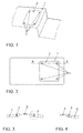
- Fig. 1 shows a perspective view of a joint assembly on the example of a vehicle roof 1 with a panoramic roof 2, wherein a first body component through the vehicle roof 1 and a second body component is formed by the panoramic roof 2.
- the vehicle roof 1 is preferably made of deep-drawn metal, in particular sheet steel or plastic and is not transparent.
- the panoramic roof 2 is made of plastic or glass and is transparent or partially transparent in particular tinted.
- holding devices 3 are provided in the rounded corner regions of the panoramic roof, their possible embodiment in the FIGS. 5 to 9 is shown. There is a different number of holding devices 3 for a variety of joining tasks in the assembly of body parts conceivable. For very small components that are to be attached to a second body component, a single holding device 3 may be sufficient.
- the holding device 3 according to the invention for supplementing a glued joint is particularly suitable for an accurate alignment of two components in the Z direction, which corresponds to the surface normal on the vehicle roof, since the second component can be pressed in the direction of gravity until it is in the desired position or that body roof and panoramic roof together, except for the transition areas, forms a continuous roof surface without cracks in the Z direction, wherein the Z direction in the vehicle is the surface normal to the vehicle roof center. Since a greater force is required for the compression of the holding devices 3 as is registered by the weight of the second body component, it is ensured that solely by the weight, in this case the panoramic roof 2, no change in position is possible.
- the method is therefore particularly suitable for all joining tasks in which the distance between the body parts to be joined is precisely specified. This can be ensured for components of any size, since only the number of holders 3 must be adapted to the size of the component or components and the desired tolerance accuracies.
- Fig. 2 shows the top view of in Fig. 1 shown assembly and Fig. 3 a lateral section according to AA in Fig. 2
- the body roof 1 an opening for the panoramic roof 2 is provided, wherein the panoramic roof 2 is arranged overlapping on this opening of the body roof 1, so that fully the body roof 1 with the panoramic roof 2 can be joined together via a gapless support surface.
- the design of the body roof 1 in the overlapping area is tapered, that is designed thinner in this area that the panoramic roof fits exactly into the resulting depression.
- the two body components 1,2 form a single continuous surface.
- the rejuvenation would instead also in the panoramic roof 2 conceivable.
- a third embodiment is possible in that both body components 1, 2 are tapered in the overlapping area, so that in turn both areas of body roof 1 and panoramic roof 2 form a continuous running surface. It can not penetrate during the use phase of the motor vehicle rain or wash water from outside to inside, since the adhesive region 6 is cohesive and sealing.
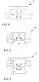
- FIG. 5 to 9 are shown in detail different embodiments for the design of the holding devices 3, wherein the embodiments in the FIGS. 5 to 8 are shown so that both body parts 1,2 are penetrated by the holding elements 5, 15, 16, 35 and the head portions of the holding elements 5, 16, 27, 35, the further penetration of the holding elements 5, 16, 27, 35 through the Prevent body parts 1, 2, are arranged raised above the body parts.
- FIG. 6 illustrated embodiment conceivable in which the head portion of the holding member 15 has been inserted into a recess of the body component, so that both together form a continuous surface.
- An advantageous embodiment, here in FIG. 7 is shown, is that the holding element 25, the body component 2 does not penetrate, but is attached to the underside and in this way, both body parts 1, 2 interconnected.
- the holding element may be fastened to the body or mounted in a recess provided for the holding element in the body component.
- the first or second body component is referred to below as an example body part roof 1 and the panoramic roof 2, but can be found anywhere in vehicle application.
- a first embodiment of a one-piece holding device 13 which consists of a single holding element 5.
- the holding element 5 consists of a pin-shaped area, which fits its size through the openings of the body components and a head portion, which excludes a deeper penetration into the body part 2 due to its size.
- the body roof 1 is located below the panoramic roof 2 in the transition region in which overlap both body parts 1.2. In between, a layer of adhesive 6 is arranged.
- an opening is provided, through which the holding member 5 is carried out without resistance.
- the opening is provided such that the holding member 5 is pressed against a resistance in the opening.
- a positive locking device 3 incorporated steps, notches or teeth in the longitudinal direction of the holding element 5 are present, so that the detents of a holding element 5 from one to the next stage, in this case in the body roof 1, jumps.
- a second embodiment of a two-part holding device 23 wherein a first holding element 16 is anchored in a second holding element 15.
- the anchoring of the holding elements 15 and 16 is also provided here by locking teeth along the holding elements 15, 16, which interlock positively with each other, wherein the holding element 16 in an opening of the holding element 15 is inserted.
- the holding element 15 has the latching teeth arranged in the longitudinal direction on its inner side and the holding element 16 on its outer side.
- the holding elements 15 and 16 consist of a pin-shaped area which can be moved through the openings provided in the body parts 1 and 2 and a head part, which prevents further movement of the holding elements 15 and 16 through these openings by he due to its size with the body components makes a stop.
- the panoramic roof has a recess in this embodiment, so that the head of the holding element 15 is completely in this depression and forms a uniform surface with the panoramic roof.
- the body roof 1 is arranged in the transition region of the body parts 1, 2 below the panoramic roof 2 with an intermediate layer of adhesive 6. In both body parts 1 and 2, an opening is provided, through which the holding elements 15 and 16 are flush.
- a third embodiment of a three-part holding device 33 is shown, wherein a first holding element 26 is anchored in two other identical retaining elements 25 and 27.
- the anchoring of the support member 26 in the support members 25 and 27 is also provided here by locking teeth along the support members which interlock positively with each other, wherein the support member 26 is inserted into each of the openings of the support members 25 and 27, that is, the ratchet teeth the holding elements 25, 26 are provided on its inner side and on the holding element 26 respectively on the outside.
- the holding member 27 consists of a pin-shaped portion which can be moved through the openings provided in the body components 1 and a head portion which prevents further movement of the holding member 27 through these openings.
- the holding element 25, also formed here with a head, is fixedly attached to the underside of the body component 2, here in a recess provided for this purpose.
- the holding member 26 is consistently pin-shaped in a constant width with external latching teeth for locking in the holding elements 25,27 carried out so that it can be introduced with approximately half the total length in both the holding member 25 and in the holding member 27 and thus positioned the body parts.
- the body roof 1 is arranged in the transition region of the body parts 1, 2 below the panoramic roof 2 with an intermediate layer of adhesive 6. In both body parts 1 and 2, an opening is provided through which the holding elements 25 and 27 are flush.
- FIG. 8 A fourth embodiment of a two-part holding device 43 is shown, wherein a first holding element 35 is anchored in a second holding element 36.
- the anchoring of the holding elements 35 and 36 is provided here by frictional engagement, wherein the retaining element 35 is inserted into an opening of the holding element 36 and the opening in the holding element 36 is just so large that the holding element 35 must be pressed with a force greater than the gravity of the overhead body component, here the panoramic roof 2, in the holding member 36, so that there is a press fit.
- the holding member 35 consists of a pin-shaped portion which can be moved through the openings provided in the body components 1 and 2 and a head portion which prevents further movement of the holding member 35 through these openings.
- the body roof 1 is arranged in the transition region of the body parts 1, 2 below the panoramic roof 2 with an intermediate layer of adhesive 6.
- an opening is provided through which the holding members 35 and 36 are flush.
- the holding device 43 secures by friction the positions of the body parts to each other, in which case a one-, two- or three-part construction of the holding device is also possible.
- the holding elements have different material properties, so that an intermediate holding element, as in Fig. 7 Comparable with the holding element 26, in a three-part design is softer than the other two holding elements, so that it has such plastic properties that yields when pressed the two other holding elements in the mold.
- the holding devices 43 which ensure the positioning of the body components by means of friction, a continuous positioning of the components to each other is possible.
- a fifth embodiment of a holding device 53 which ensures the positioning of the body parts by means of a single plastically deformable retaining element 45a, which also must be ensured that no plastic deformation by the weight forces of the body parts, even over a longer period, are possible.
- the retaining element 45a becomes the retaining element 45b after the joining operation due to the deformation. Even with a holding device 3 with plastically deformable holding elements stepless positioning is possible.
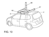
- Fig. 10 the assembly of the roof by means of a manipulator 46 is shown.
- the manipulator 46 has a two-part gripping means, an outer frame 47 which is fixed to the manipulator and an inner frame 48 for holding the panoramic roof 2.
- the position of the panoramic roof 2 is referenced directly to the position of the body roof 1.
- the two-piece gripping means with an outer frame 47 and an inner frame 48 is provided with a mechanism which references the surrounding contour. Once the contour of the body roof 1 is touched, the end position of the manipulator 46 is determined by this touch.
- the outer frame 47 initially moves into a pre-centered position until a reference sensor 50 attached to this frame 47 indicates the end position of the stroke.
- the reference sensor 50 may be mechanically or directly coupled. There are electrical and pneumatic sensors conceivable that are indirectly coupled to the stop.
- holding devices 3, 13, 23, 33, 43, 53 are provided, which are arranged so that they are initially selectively attached to one of the two body components 1, 2 and locked exactly in one another while the inner frame 48 is moved to its target position, what they need to be aligned exactly. In the target position, that is, when the inner frame 48 stops moving, the holding device 3, 13, 23, 33, 43, 53 ensure that, even after removing the components from the two frames 47, 48, their positioning relative to one another is unchangeable remains.
- Fig. 11 is a possible detail view Y of Fig. 10 is shown by means of a reference sensor 50 for controlling a servo motor 49, so that an exact positioning of the panoramic roof 2 on the surface of the body roof 1 is ensured.
- the reference sensor 50 is mounted on the outer frame 47 and moves together with this in the direction of body roof 1. If the reference sensor 50 indicates the desired distance or touches the body roof, depending on the embodiment, so stops the servomotor 49, the velvet outer frame 47 together Reference sensor 50 moves.
- the reference sensor 50 can operate mechanically, photoelectrically, magnetically, by means of an ultrasonic sensor, by means of measurement with the Hall effect or other measuring methods.
- the inner frame 48 which carries the panoramic roof 2 moves against the outer frame 47, so that an exact positioning of the two body parts 1, 2 is ensured to each other. If the holding devices 3, 13, 23, 33, 43, 53 are brought into their target position, the curing begins the adhesive in the adhesive bead 6 without the position of the body parts to each other can change until fully cured.
- Fig. 12 is a second possible detail view Y of Fig. 10 is shown by means of a mechanically coupled reference sensor 51 for controlling a pneumatic cylinder 52, so that an exact positioning of the panoramic roof 2 is ensured on the surface of the body roof 1.
- the reference sensor 51 is attached to the outer frame 47 and moves along with it in the direction of body roof 1. Touches the reference sensor 51, the body roof so the pneumatic cylinder 52, which moves the outer frame 47 together with reference sensor 51, stops any further movement.
- the inner frame 48 which carries the panoramic roof 2 moves against the outer frame 47, so that an exact positioning of the two body parts 1, 2 is ensured to each other. If the holding devices 3, 13, 23, 33, 43, 53 are brought into their target position, then the curing of the adhesive in the adhesive bead 6 begins without the position of the body components being able to change until complete curing.
Landscapes
- Engineering & Computer Science (AREA)
- Mechanical Engineering (AREA)
- Chemical & Material Sciences (AREA)
- Combustion & Propulsion (AREA)
- Transportation (AREA)
- General Engineering & Computer Science (AREA)
- Manufacturing & Machinery (AREA)
- Body Structure For Vehicles (AREA)
- Automobile Manufacture Line, Endless Track Vehicle, Trailer (AREA)
- Standing Axle, Rod, Or Tube Structures Coupled By Welding, Adhesion, Or Deposition (AREA)
Abstract
Description
- Die Erfindung betrifft eine Fügeanordnung von mindestens zwei Karosseriebauteilen eines Fahrzeugs mit einem ersten Fügebauteil und zumindestens einem zweiten Fügebauteil, wobei mindestens eine Haltevorrichtung zur Verbindung vorgesehen ist. Diese Haltevorrichtung ermöglicht eine arretierende Verbindung zwischen den Karosseriebauteilen. Des Weiteren befindet sich zwischen den Bauteilen im Fügebereich ein zuvor aufgebrachter Kleber.
- Aus der
WO2010/127884 ist eine Fügeanordnung zum Fügen von Fügepartnern eines Fahrzeugs bekannt. Es wird ein Fügepartner mit mindestens einem zweiten Fügepartner über eine Haltevorrichtung verbunden. Der Kleber ist hier vorher innerhalb des Halteelementes aufgetragen, wobei die Positionierung in einer Richtung solange erfolgen kann, wie der Kleber nicht ausgehärtet ist. Auch hierbei werden vorkonfektionierte Baugruppen eines Fahrzeuges in eine genau definierte Lage zu einem Karosserieteil des Fahrzeuges ausgerichtet. Hier werden insbesondere die Baugruppen Frontendmodul, Rearendmodul, Heckklappe, Türmodul, Stoßfänger, insbesondere Stoßfängerüberzug an ein Karosserieteil des Fahrzeugs benannt, außerdem Leuchteinheiten mit oder ohne Montageträger und/oder einer Cockpiteinheit im Fahrzeug. Bei diesem Verfahren ist eine Veränderung der Lage der Karosseriebauteile zueinander durch leichte Krafteinwirkung möglich. Die Gewichtskraft eines Bauteils würde ausreichen eine Verlagerung zu bewirken. Darin besteht auch der Nachteil dieses Verfahrens, dass es nicht für eine Ausrichtung in oder gegen die z-Achse geeignet ist. Die z-Achse bezeichnet im Fahrzeugbau allgemein die Achse durch die Fahrzeugmitte als Normale zum gedachten Straßenverlauf also senkrecht zur Fahrzeugdachmitte. - Bisher war eine klebende Verbindung zweier Karosseriebauteile nicht exakt zueinander positionierbar, da der Kleber im Laufe des Aushärtevorganges noch nachgibt, schrumpft oder sich auf andere Weise verformt. Durch die nun zusätzlich eingebrachten Halteelemente ist eine exakte Positionierung von den Karosseriebauteilen zueinander gesichert. Es findet keine Änderung der Position während des Aushärtevorganges mehr statt, da die Haltevorrichtungen nur unter Krafteinwirkung in Position gebracht werden können. Die Haltevorrichtungen verbleiben an den Bauteilen.
- Aufgabe der vorliegenden Erfindung ist es, eine Fügeanordnung zum Fügen von Karosseriebauteilen zu schaffen, bei der die Positionierung der Bauteile zueinander sichergestellt ist.
- Der besondere Vorteil des Verfahrens ist, dass selbst sehr große Karosseriebauteile unter gesicherten Toleranzwerten aneinander gefügt werden können und dies auch mit einem Kleber, der erst nach der Aushärtephase seine Viskosität weitgehend verliert und deshalb alleine verwendet eine sichere Positionierung nicht gewährleisten könnte.
- Zur Lösung dieser Aufgabe wird eine Fügeanordnung mit den Merkmalen des Anspruches 1 und ein Verfahren zum Fügen mit den Merkmalen des Anspruchs 9 vorgeschlagen. In den abhängigen Ansprüchen sind bevorzugte Weiterbildungen ausgeführt.
- Erfindungsgemäß ist eine Fügeanordnung von mindestens zwei Karosseriebauteilen eines Fahrzeuges mit einem ersten Fügebauteil und zumindest einem zweiten Fügebauteil vorgeschlagen, wobei mindestens eine Haltevorrichtung zur arretierbaren Verbindung vorgesehen ist. Die Haltevorrichtung stellt bei dieser Fügeanordnung sicher, dass der zwischen den Karosseriebauteilen eingefügte Kleber aushärtet, ohne dass sich die Position der Bauteile durch Nachgeben des Klebers während des Aushärtens verändert. Vorteil dieser Erfindung ist, dass die Positionierung durch die Haltevorrichtung mit dem Zeitpunkt des Zusammenfügens sichergestellt ist. Der Kleber kann an anderen Stellen und/oder an den Haltelementen, in flächiger oder punktueller Form oder die gesamten Fügebereiche abdichtend aufgebracht sein.
- Insbesondere weist die Fügeanordnung zwei, drei oder vorzugsweise vier Haltevorrichtungen auf. Vorteilhaft sind für sehr große Karosseriebauteile auch mehr Haltevorrichtungen im Fügebereich der Karosseriebauteile vorgesehen, so dass eine exakte Positionierung auch über große Fügebereiche sichergestellt ist.
- Bevorzugt ist zumindest eine Haltevorrichtung ein- oder mehrteilig ausgeführt. Die einteilige Haltevorrichtung ist als Stift an einem der beiden Fügebauteile mit einer Lochung am anderen Fügebauteil denkbar, so dass der Stift als Halteelement in der Lochung befestigt wird. Vorteilhaft ist eine einteilige Haltevorrichtung als plastisch verformbares Halteelement umgesetzt, das so weit verformt wird, bis eine gewünschte definierte Position der beiden Fügebauteile zueinander erreicht ist.
- Eine zweiteilige Ausführung der Haltevorrichtung weist insbesondere einen Stift und ein Halteelement auf, wobei das Halteelement und der Stift, durch Reibschluss oder Formschluss die genaue Positionierung der Fügebauteile sicherstellen.
- Eine dreiteilige Ausführung weist bevorzugt einen Stift oder ein erstes Halteelement, ein zweites Halteelement oder Gegenstück und ein Verbindungsteil zwischen den beiden Halteelementen auf, wobei das Verbindungselement auch plastisch verformbar sein kann. Hierbei sind reibschlüssige und/oder formschlüssige Verbindungen, die in allen Kombinationen möglich sind, vorzusehen.
- Das reibschlüssige Rasten und die plastische Verformung der Halteelemente ermöglicht eine stufenlose Positionierung, wohingegen das formschlüssige Rasten eine Positionierung in den Abstufungen der Abstände der Rastelemente in den Halteelementen vorsieht.
- Eine weitere Ausführungsform sieht ein Fügeverfahren für Karosseriebauteile mittels einer chemischen Reaktion einer Ein- oder Mehrkomponentenmasse vor.
- Bevorzugt sind die Halteelemente nur durch eine Kraft verschiebbar, die grösser ist als die Kraft durch die Wirkung der Schwerkraft der Karosseriebauteile. Die Karosseriebauteile sind damit nicht nur durch ihre Gewichtskraft allein zueinander beweglich.
- Besonders vorteilhaft an diesen Haltevorrichtungen ist, dass sie nicht nur zeitlich begrenzt die Positionierung solange sicherstellen, wie der Kleber viskos ist, sondern dass sie auch nach Aushärten des Klebers im Fahrzeug verbleiben.
- Die Fügeanordnung weist Karosseriebauteile auf, insbesondere ein Fahrzeugdach vorzugsweise aus einem Metallblech bestehend. Das Fahrzeugdach weist eine Auslassung für das Panoramadach auf, das vorzugsweise aus durchsichtigem oder teildurchsichtigem Kunststoff oder Glas besteht. Für diese Ausführung ist ein Klebebereich vorgesehen. Der Kleber ist bevorzugt umlaufend um den äußeren Rand des in das Karosseriedach einzufügenden Panoramadaches abdichtend angebracht, so dass die Klebenaht auch gleichzeitig gegen das Eindringen von Regen- oder Waschwasser von außen in das Fahrzeuginnere schützt.
- Des Weiteren wird erfindungsgemäß ein Verfahren zum Fügen von Karosseriebauteilen eines Fahrzeugs mit einem ersten Karosseriebauteil und mindestens einem zweiten Karosseriebauteil vorgeschlagen, wobei mindestens eine Haltevorrichtung vorgesehen ist. Gekennzeichnet wird das Verfahren dadurch, dass die mindestens eine Haltevorrichtung eine arretierbare Verbindung zwischen den Karosseriebauteilen sicherstellt. Dazu wird auf mindestens einem Karosseriebauteil an zumindest einer Klebestelle in dem zu fügenden Bereich Kleber aufgetragen und das zweite Karosseriebauteil unter Benetzung mit dem Kleber und Arretierung des ersten und zweiten Karosseriebauteils zueinander mittels der zumindest einer Haltevorrichtung positioniert. Der zur Positionierung notwendige Kraftaufwand ist bevorzugt deutlich höher als die durch das Gewicht eines der beiden Karosseriebauteile eingebrachte Kraft, so dass durch das Eigengewicht des oben aufliegenden Karosseriebauteils, die Haltevorrichtung in seiner Positionierung nicht veränderbar sein darf.
- Der Kleber wird insbesondere flächig, punktuell oder über den gesamten Kontaktbereich, einseitig oder auf beiden Kontaktseiten aufgebracht, wobei zumindest eine Haltevorrichtung vor oder nach dem Auftrag des Klebers angebracht wird.
- Nachdem der Kleber und die zumindest eine Haltevorrichtung aufgebracht bzw. platziert sind, werden die Karosseriebauteile zunächst über die zumindest eine Haltevorrichtung verbunden und dann soweit aufeinander gedrückt bis die gewünschte Position erreicht ist. Wirkt keine Kraft mehr von außen ein, so verändert sich auch die Position der Karosseriebauteile nicht mehr zueinander. Anschließend beginnt die Aushärtephase des Klebers und die Karosseriebauteile bleiben zueinander in der erwünschten Weise positioniert.
- Die exakte Ausrichtung der Karosseriebauteile zueinander erfolgt vorteilhaft mittels eines Manipulators oder mit Hilfe eines Roboters wobei die vorbestimmte Position jeweils mit der tatsächlichen Position abgeglichen wird. Dies erfolgt vorteilhaft mittels elektrischer oder photoelektrischer Sensoren. Des Weiteren sind pneumatische Sensoren oder eine Abstandsdetektion unter Ausnutzung des Hall-Effektes zur Positionsbestimmung denkbar.
- Das Verfahren ist im vorliegenden Fall dazu geeignet ein Karosseriebauteil derartig an das zweite Karosseriebauteil eines Kraftfahrzeuges anzufügen, dass die Bauteile formschlüssig miteinander eine stetig verlaufende Fläche bzw. Flächenkontur bilden.
- Bevorzugt um eine exakte Positionierung der Karosseriebauteile zueinander sicherzustellen ist die Verwendung eines zweiteiligen Greifmittels, bestehend aus einem Innen- und einem Außenrahmen, möglich. Durch diese Greifmittel wird die Endlage eines Manipulators so festgelegt, dass das erste Karosseriebauteil an der Kontur des zweiten Karosseriebauteils referenziert wird.
- Bevorzugt wird mit dem erfindungsgemäßen Verfahren die Montage eines Panoramadaches an das Karosseriedach eines Kraftfahrzeuges durchgeführt.
- Weitere Vorteile, Merkmale und Einzelheiten der Erfindung ergeben sich aus der nachfolgenden Beschreibung, in der unter Bezugnahme auf die Zeichnungen ein mögliches Ausführungsbeispiel der Erfindung im Einzelnen beschrieben ist. Es zeigen:
-
Fig. 1 eine perspektivische Darstellung einer Fügeanordnung am Beispiel eines Fahrzeugdaches, wobei ein erstes Karosseriebauteil durch das Fahrzeugdach und ein zweites Karosseriebauteil durch das Panoramadach gebildet wird, -
Fig. 2 eine Draufsicht auf die Fügeanordnung nachFig. 1 , -
Fig. 3 eine Schnittdarstellung gemäß Schnitt A - A inFig. 2 , -
Fig. 4 ein Detail X aus dem Schnitt A - A ausFig. 3 , -
Fig. 5 eine Schnittdarstellung gemäß einer ersten Ausführung der Fügeanordnung mit einer einteiligen Haltevorrichtung und formschlüssiger Arretierung, -
Fig. 6 eine Schnittdarstellung gemäß einer zweiten Ausführung der Fügeanordnung mit einer zweiteiligen Haltevorrichtung und formschlüssiger Arretierung, -
Fig. 7 eine Schnittdarstellung gemäß einer dritten Ausführung der Fügeanordnung mit einer dreiteiligen Haltevorrichtung und formschlüssiger Arretierung, -
Fig. 8 eine Schnittdarstellung gemäß einer vierten Ausführung der Fügeanordnung mit einer zweiteiligen Haltevorrichtung und reibschlüssiger Arretierung, -
Fig. 9a, 9b eine Schnittdarstellung gemäß einer fünften Ausführung der Fügeanordnung mit einer einteiligen Haltevorrichtung und arretierend mittels eines plastisch verformbaren Halteelements vor und nach der Verformung, -
Fig. 10 eine Schnittdarstellung durch die Fügeanordnung mit einem Manipulator, -
Fig. 11 ein Detail Y aus der Schnittdarstellung durch die Fügeanordnung mit einem Manipulator und Stellantrieb in der Detailansicht, -
Fig. 12 ein Detail Y aus der Schnittdarstellung durch die Fügeanordnung mit einem Manipulator ohne Nachstellen in der Detailansicht, -
Fig. 1 zeigt eine perspektivische Darstellung einer Fügeanordnung am Beispiel eines Fahrzeugdaches 1 mit einem Panoramadach 2, wobei ein erstes Karosseriebauteil durch das Fahrzeugdach 1 und ein zweites Karosseriebauteil durch das Panoramadach 2 gebildet ist. Das Fahrzeugdach 1 besteht vorzugsweise aus tiefgezogenem Metall, insbesondere Stahlblech oder aus Kunststoff und ist nicht durchsichtig. Das Panoramadach 2 besteht aus Kunststoff oder Glas und ist durchsichtig oder teildurchsichtig insbesondere getönt. - Des Weiteren sind in diesem Ausführungsbeispiel vier Haltevorrichtungen 3 in den abgerundeten Eckbereichen des Panoramadachs vorgesehen, deren mögliche Ausgestaltung in den
Figuren 5 bis 9 dargestellt ist. Es ist eine unterschiedliche Anzahl von Haltevorrichtungen 3 für unterschiedlichste Fügeaufgaben in der Montage von Karosseriebauteilen denkbar. Bei sehr kleinen Bauteilen, die an einem zweiten Karosseriebauteil befestigt werden sollen, ist gegebenenfalls eine einzelne Haltevorrichtung 3 ausreichend. Die erfindungsgemäße Haltevorrichtung 3 zur Ergänzung einer geklebten Fügung ist besonders geeignet für eine genaue Angleichung zweier Bauteile in Z-Richtung, die der Oberflächennormalen auf dem Fahrzeugdach entspricht, da das zweite Bauteil so lange in Schwerkraftrichtung gedrückt werden kann, bis es in der gewünschten Position liegt, bzw. dass Karosseriedach und Panoramadach gemeinsam, abgesehen von den Übergangsbereichen, eine stetige Dachfläche ohne Sprünge in Z-Richtung bildet, wobei die Z-Richtung im Fahrzeugbau die Oberflächennormale zum Fahrzeugdachmittelpunkt ist. Da für das Zusammendrücken der Haltevorrichtungen 3 eine größere Kraft nötig ist als durch die Gewichtskraft des zweiten Karosseriebauteiles eingetragen wird, ist sichergestellt, dass allein durch die Gewichtskraft, in diesem Falle des Panoramadaches 2, keine Veränderung der Position mehr möglich ist. Das Verfahren ist daher für alle Fügeaufgaben besonders geeignet, bei denen der Abstand der zu fügenden Karosseriebauteile genau vorgegeben ist. Dies kann für Bauteile in beliebiger Größe sichergestellt werden, da lediglich die Anzahl der Haltevorrichtungen 3 an die Größe des Bauteiles oder der Bauteile und der gewünschten Toleranzgenauigkeiten angepasst werden muss. -
Fig. 2 zeigt die Draufsicht der inFig. 1 dargestellten Baugruppe undFig. 3 einen seitlichen Schnitt gemäß A-A inFig. 2 . In dem Karosseriedach 1 ist eine Öffnung für das Panoramadach 2 vorgesehen, wobei das Panoramadach 2 überlappend auf dieser Öffnung des Karosseriedaches 1 angeordnet ist, so dass vollumfänglich das Karosseriedach 1 mit dem Panoramadach 2 über eine lückenlose Auflagefläche zusammen gefügt werden kann. Damit bei einer überlappenden Ausführung der beiden Karosseriebauteile 1, 2 die Flächen trotzdem stetig verlaufen, ist die Ausführung des Karosseriedaches 1 im Überlappungsbereich derartig verjüngt, das heißt in diesem Bereich dünner ausgestaltet, dass das Panoramadach genau in die dadurch entstandene Vertiefung passt. Die beiden Karosseriebauteile 1,2 bilden eine einzige stetig verlaufende Fläche. Die Verjüngung wäre stattdessen ebenfalls im Panoramadach 2 denkbar. Eine dritte Ausführungsart ist möglich, indem beide Karosseriebauteile 1, 2 im Überlappungsbereich verjüngt sind, so dass wiederum beide Flächen von Karosseriedach 1 und Panoramadach 2 eine stetig ineinander laufende Fläche bilden. Es kann während der Gebrauchsphase des Kraftfahrzeuges kein Regen- oder Waschwasser von außen nach innen eindringen, da der Klebebereich 6 stoffschlüssig und abdichtend ist. - In
Fig. 5 bis 9 sind detailliert unterschiedliche Ausführungsbeispiele für die Ausgestaltung der Haltevorrichtungen 3 dargestellt, wobei die Ausführungsbeispiele in denFiguren 5 bis 8 so dargestellt sind, dass beide Karosseriebauteile 1,2 von den Halteelementen 5, 15, 16, 35 durchdrungen werden und die Kopfbereiche der Haltelemente 5, 16, 27, 35, die ein weiteres Durchdringen der Haltelemente 5, 16, 27, 35 durch die Karosseriebauteile 1, 2 verhindern, erhaben über den Karosseriebauteilen angeordnet sind. Außerdem ist hier eine in derFigur 6 dargestellte Ausführung denkbar, bei der der Kopfbereich des Halteelements 15 in eine Vertiefung des Karosseriebauteils eingelassen wurde, so dass beide miteinander eine stetige Fläche bilden. Eine vorteilhafte Ausführung, die hier inFigur 7 dargestellt ist, besteht darin dass das Halteelement 25 das Karosseriebauteil 2 nicht durchdringt, sondern an dessen Unterseite befestigt ist und auf diese Weise beide Karosseriebauteile 1, 2 miteinander verbindet. Hierbei kann das Halteelement an der Karosserie befestigt sein oder in einer für das Halteelement vorgesehene Vertiefung im Karosseriebauteil angebracht sein. Diese drei unterschiedlichen Anbindungen an den Karosseriebauteilen sind in denFiguren 5 bis 8 beispielhaft dargestellt und sind in jeder Kombination denkbar.
Das erste oder zweite Karosseriebauteil ist im Folgenden beispielhaft als Karosseriebauteil-Dach 1 als auch das Panoramadach 2 bezeichnet, kann aber überall im Fahrzeugbau Anwendung finden. - In
Fig. 5 ist eine erste Ausführungsform einer einteilige Haltevorrichtung 13 gezeigt, die aus einem einzigen Halteelement 5 besteht. Das Halteelement 5 besteht aus einem stiftförmigen Bereich, der seiner Größe nach durch die Öffnungen der Karosseriebauteile passt und einem Kopfbereich, der aufgrund seiner Größe ein tieferes Eindringen in das Karosseriebauteil 2 ausschließt. Das Karosseriedach 1 ist im Übergangsbereich, in dem sich beide Karosseriebauteile 1,2 überlappen, unterhalb des Panoramadachs 2 angeordnet. Dazwischen ist eine Schicht Kleber 6 angeordnet. Im Panoramadach 2 ist eine Öffnung vorgesehen, durch die das Halteelement 5 widerstandsfrei durchzuführen ist. In Gegensatz dazu ist im Karosseriedach 1 die Öffnung derart vorgesehen, dass das Halteelement 5 gegen einen Widerstand in die Öffnung gedrückt wird. Die am Haltelement 5 vorgesehenen Rastzähne längs des Halteelements 5 verhaken sich formschlüssig im Karosseriedach 1. Bei einer formschlüssigen Haltevorrichtung 3 sind eingearbeitete Stufen, Rasten oder Zähne in Längsrichtung des Halteelements 5 vorhanden, so dass die Rasten eines Halteelementes 5 von einer zur nächsten Stufe, in diesem Fall in dem Karosseriedach 1, springt. - In
Fig. 6 ist eine zweite Ausführungsform einer zweiteiligen Haltevorrichtung 23 gezeigt, wobei ein erstes Halteelement 16 in einem zweiten Halteelement 15 verankert ist. Die Verankerung der Haltelemente 15 und 16 ist auch hier durch Rastzähne längs der Halteelemente 15, 16 vorgesehen, die sich formschlüssig ineinander verhaken, wobei das Halteelement 16 in eine Öffnung des Halteelementes 15 eingefügt wird. Das Halteelement 15 weist die in Längsrichtung angeordneten Rastzähnchen an seiner Innenseite auf und das Halteelement 16 an seiner Außenseite. Die Halteelemente 15 und 16 bestehen aus einem stiftförmigen Bereich, der sich durch die vorgesehenen Öffnungen in den Karosseriebauteilen 1 und 2 bewegen lässt und einem Kopfteil, der eine weitere Bewegung der Halteelemente 15 und 16 durch diese Öffnungen verhindert indem er aufgrund seiner Größe mit den Karosseriebauteilen einen Anschlag bildet. Das Panoramadach hat in diesem Ausführungsbeispiel eine Vertiefung, so dass der Kopf des Halteelements 15 vollständig in dieser Vertiefung liegt und mit dem Panoramadach eine einheitliche Fläche bildet. Das Karosseriedach 1 ist im Übergangsbereich der Karosseriebauteile 1, 2 unterhalb des Panoramadachs 2 mit einer dazwischen liegenden Schicht Kleber 6 angeordnet. In beiden Karosseriebauteilen 1 und 2 ist eine Öffnung vorgesehen, durch die die Halteelemente 15 und 16 bündig durchzuführen sind. - In
Fig. 7 ist eine dritte Ausführungsform einer dreiteiligen Haltevorrichtung 33 gezeigt, wobei ein erstes Halteelement 26 in zwei weiteren baugleichen Halteelementen 25 und 27 verankert ist. Die Verankerung des Halteelements 26 in den Halteelementen 25 und 27 ist auch hier durch Rastzähne längs der Halteelemente vorgesehen, die sich formschlüssig ineinander verhaken, wobei das Halteelement 26 jeweils in die Öffnungen der Halteelemente 25 und 27 eingefügt wird, das heißt, dass die Rastzähne an den Halteelementen 25, 26 auf ihrer Innenseite und an dem Halteelement 26 jeweils an der Außenseite vorgesehen sind. Das Haltelement 27 besteht aus einem stiftförmigen Bereich, der sich durch die vorgesehenen Öffnungen in den Karosseriebauteilen 1 bewegen lässt und einem Kopfteil, der eine weitere Bewegung des Halteelements 27 durch diese Öffnungen verhindert. Das Halteelement 25, hier ebenfalls mit einem Kopf ausgebildet, ist an der Unterseite von Karosseriebauteil 2, hier in einer dafür vorgesehenen Vertiefung, fest angebracht. Das Halteelement 26 ist durchgängig stiftförmig in gleichbleibender Breite mit außenliegenden Rastzähnchen zur Verrastung in den Haltelementen 25,27 ausgeführt, so dass es jeweils mit etwa halber Gesamtlänge sowohl in das Haltelement 25 als auch in das Halteelement 27 eingeführt werden kann und somit die Karosseriebauteile positioniert. Bei dieser Variante ist es denkbar zunächst zwei Halteelemente 25 und 26 miteinander zu verbinden und anschließend das dritte Halteelement 27 zu positionieren. Das Karosseriedach 1 ist im Übergangsbereich der Karosseriebauteile 1, 2 unterhalb des Panoramadachs 2 mit einer dazwischen liegenden Schicht Kleber 6 angeordnet. In beiden Karosseriebauteilen 1 und 2 ist eine Öffnung vorgesehen, durch die die Halteelemente 25 und 27 bündig durchzuführen sind. - In
Fig. 8 ist eine vierte Ausführungsform einer zweiteiligen Haltevorrichtung 43 gezeigt, wobei ein erstes Halteelement 35 in einem zweiten Halteelement 36 verankert ist. Die Verankerung der Haltelemente 35 und 36 ist hier durch Reibschluss vorgesehen, wobei das Halteelement 35 in eine Öffnung des Halteelementes 36 eingefügt wird und die Öffnung im Halteelement 36 gerade so groß ist, dass das Halteelement 35 mit einer Kraft größer als der Schwerkraft des oben liegenden Karosseriebauteils, hier die des Panoramadaches 2, in das Halteelement 36 gedrückt werden muss, so dass sich eine Presspassung ergibt. Das Haltelement 35 besteht aus einem stiftförmigen Bereich, der sich durch die vorgesehenen Öffnungen in den Karosseriebauteilen 1 und 2 bewegen lässt und einem Kopfteil, der eine weitere Bewegung des Halteelements 35 durch diese Öffnungen verhindert. Das Karosseriedach 1 ist im Übergangsbereich der Karosseriebauteile 1, 2 unterhalb des Panoramadachs 2 mit einer dazwischen liegenden Schicht Kleber 6 angeordnet. In beiden Karosseriebauteilen 1 und 2 ist eine Öffnung vorgesehen, durch die die Halteelemente 35 und 36 bündig durchzuführen sind. Die Haltevorrichtung 43 sichert mittels Reibschluss die Positionen der Karosseriebauteile zueinander, wobei hierbei ein ein-, zwei- oder dreiteiliger Aufbau der Haltevorrichtung ebenfalls möglich ist. Hierbei ist auch denkbar, dass die Halteelemente unterschiedliche Materialeigenschaften aufweisen, so dass ein zwischenliegendes Halteelement, wie inFig. 7 mit dem Haltelement 26 vergleichbar, bei einer dreiteiligen Ausführung weicher ist als die andern beiden Halteelemente, so dass es derartige plastische Eigenschaften hat, dass beim Andrücken den beiden übrigen Halteelementen in der Form nachgibt. Bei den Haltevorrichtungen 43, die mittels Reibschluss die Positionierung der Karosseriebauteile sicherstellen, ist eine stufenlose Positionierung der Bauteile zueinander möglich. - In
Fig. 9 ist eine fünfte Ausführungsform einer Haltevorrichtung 53 gezeigt, die die Positionierung der Karosseriebauteile mittels eines einzelnen plastisch verformbaren Halteelements 45a sicherstellt, wobei auch hier gewährleistet sein muss, dass keinerlei plastische Verformung durch die Gewichtskräfte der Karosseriebauteile, auch nicht über einen längeren Zeitraum, möglich sind. Das Halteelement 45a wird nach dem Fügevorgang durch die Verformung zu dem Halteelement 45b. Auch bei einer Haltevorrichtung 3 mit plastisch verformbaren Halteelementen ist eine stufenlose Positionierung möglich. - Es ist auch eine Kombination unterschiedlicher Ausführungen von Halteelementen denkbar um die Vorteile der jeweiligen Fügemöglichkeiten zu nutzen. Auch wenn an unterschiedlichen Fügebereichen der Karosseriebauteile unterschiedliche Kräfte wirken, so kann diesem Aspekt durch geeignete Auslegung der Haltevorrichtungen 3 Rechnung getragen werden. Es ist denkbar, dass die Ansprüche an die Lastaufnahmekapazität der Halteelemente unterschiedlich sind. Liegt beispielsweise die höchste Gewichtslast eines Karosseriebauteiles an einer ersten Stelle an, so kann an dieser Stelle eine zweiteilige Haltevorrichtung, die durch Formschluss oder Reibschluss die Positionierung sicherstellt vorgesehen werden, während an einer anderen Stelle, an der Gewichtskräfte des Karosseriebauteils keine oder nur eine geringe Rolle spielen ein plastisch verformbares einzelnes Halteelement als Haltevorrichtung vorgesehen werden kann, das lediglich die Aufgabe hat eine Positionierung sicherzustellen ohne große Kräfte aufnehmen zu müssen.
- In
Fig. 10 ist die Montage des Daches mittels eines Manipulators 46 gezeigt. Der Manipulator 46 weist ein zweiteiliges Greifmittel, einem äußeren Rahmen 47, der am Manipulator befestigt ist und einem inneren Rahmen 48 zur Halterung des Panoramadaches 2 auf. Vorteilhafterweise wird bei diesem Verfahren die Position des Panoramadaches 2 direkt an der Position des Karosseriedaches 1 referenziert. Das zweiteilige Greifmittel mit einem äußeren Rahmen 47 und einem inneren Rahmen 48 ist mit einem Mechanismus ausgestattet, der sich an der umgebenden Kontur referenziert. Sobald die Kontur des Karosseriedaches 1 berührt wird, ist durch diese Berührung die Endlage des Manipulators 46 festgelegt. Erfindungsgemäß fährt der äußere Rahmen 47 zunächst in eine vorzentrierte Position bis ein, an diesem Rahmen 47 angebrachter Referenzfühler 50 die Endlage des Hubes anzeigt. Anschließend wird der äußere Rahmen 47 genau hier blockiert, damit der innere Rahmen 48 in entgegengesetzter Richtung zum äußeren Rahmen 47 genau bis zu diesem gefahren werden kann und dort dann blockiert. Der Referenzfühler 50 kann mechanisch oder direkt gekoppelt sein. Es sind elektrische und pneumatische Sensoren denkbar, die indirekt mit dem Anschlag gekoppelt sind. Außerdem sind Haltevorrichtungen 3, 13, 23, 33, 43, 53 vorgesehen, die so angeordnet sind, dass sie zunächst wahlweise an einem der beiden Karosseriebauteile 1,2 angebracht werden und exakt ineinander verrasten während der innere Rahmen 48 in seine Zielposition gefahren wird, wozu sie exakt ausgerichtet sein müssen. In der Zielposition, das heißt, wenn der innere Rahmen 48 sich nicht mehr bewegt, stellen die Haltevorrichtung 3, 13, 23, 33, 43, 53 sicher, dass auch nach Entfernen der Bauteile aus den beiden Rahmen 47, 48 deren Positionierung zueinander unveränderlich bleibt. - In
Fig. 11 ist eine mögliche Detailansicht Y vonFig. 10 mittels eines Referenzfühlers 50 zur Steuerung eines Stellmotors 49 gezeigt, so dass eine exakte Positionierung des Panoramadaches 2 an der Fläche des Karosseriedaches 1 sichergestellt ist. Hierbei ist der Referenzfühler 50 am äußeren Rahmen 47 angebracht und bewegt sich zusammen mit diesem in Richtung Karosseriedach 1. Signalisiert der Referenzfühler 50 den angestrebten Abstand oder berührt er das Karosseriedach, je nach Ausführungsart, so stoppt der Stellmotor 49, der den äußeren Rahmen 47 samt Referenzfühler 50 bewegt. Der Referenzfühler 50 kann mechanisch, photoelektrisch, magnetisch, mittels eines Ultraschall-Sensors, mittels Messung mit dem Hall-Effekt oder anderen Messmethoden arbeiten. In der Folge fährt nun der innere Rahmen 48, der das Panoramadach 2 trägt, gegen den äußeren Rahmen 47, so dass eine exakte Positionierung beider Karosseriebauteile 1, 2 zueinander sichergestellt ist. Sind die Haltevorrichtungen 3, 13, 23, 33, 43, 53 in ihre Zielposition gebracht, so beginnt die Aushärtung des Klebers in der Kleberaupe 6 ohne dass sich die Position der Karosseriebauteile zueinander bis zur vollständigen Aushärtung noch verändern kann. - In
Fig. 12 ist eine zweite mögliche Detailansicht Y vonFig. 10 mittels eines mechanisch gekoppelten Referenzfühlers 51 zur Steuerung eines Pneumatikzylinders 52 gezeigt, so dass eine exakte Positionierung des Panoramadaches 2 an der Fläche des Karosseriedaches 1 sichergestellt ist. Hierbei ist der Referenzfühler 51 am äußeren Rahmen 47 angebracht und bewegt sich zusammen mit diesem in Richtung Karosseriedach 1. Berührt der Referenzfühler 51 das Karosseriedach so stoppt der Pneumatikzylinder 52, der den äußeren Rahmen 47 samt Referenzfühler 51 bewegt, jede weitere Bewegung. In der Folge fährt nun der innere Rahmen 48, der das Panoramadach 2 trägt, gegen den äußeren Rahmen 47, so dass eine exakte Positionierung beider Karosseriebauteile 1, 2 zueinander sichergestellt ist. Sind die Haltevorrichtungen 3, 13, 23, 33, 43, 53 in ihre Zielposition gebracht, so beginnt die Aushärtung des Klebers in der Kleberaupe 6 ohne dass sich die Position der Karosseriebauteile zueinander bis zur vollständigen Aushärtung noch verändern kann. - Die Erfindung beschränkt sich in Ihrer Ausführung nicht auf das vorstehend angegebene bevorzugte Ausführungsbeispiel. Vielmehr ist eine Anzahl von Varianten denkbar, welche von der dargestellten Lösung auch bei grundsätzlich anders gearteten Ausführungen Gebrauch macht. Sämtliche aus den Ansprüchen, der Beschreibung oder den Zeichnungen hervorgehenden Merkmale und/oder Vorteile, einschließlich konstruktiver Einzelheiten, räumliche Anordnungen und Verfahrensschritte, können sowohl für sich als auch in den verschiedensten Kombinationen erfindungswesentlich sein.
-
- 1, 2
- Karosseriebauteil
- 3, 13, 23, 33, 43, 53a, 53b
- Haltevorrichtung
- 5,15,16,25,26,27,35,36,45a,45b
- Halteelement
- 6
- Klebefläche
- 46
- Manipulator
- 47
- äußerer Rahmen
- 48
- innerer Rahmen
- 49
- Stellmotor
- 50, 51
- Referenzfühler
- 52
- Pneumatikzylinder
Claims (13)
- Fügeanordnung von mindestens zwei Karosseriebauteilen (1,2) eines Fahrzeuges mit einem ersten Fügebauteil und zumindestens einem zweiten Fügebauteil, wobei mindestens eine Haltevorrichtung (3) zur arretierbaren Verbindung vorgesehen ist, dadurch gekennzeichnet, dass zusätzlich zu der zumindest einen Haltevorrichtungen mindestens eine Klebestelle (6) an den Fügebereichen der Fügebauteile vorgesehen ist, so dass zumindest in einem Bereich miteinander verklebte Fügebauteile in ihrer Positionierung zueinander während des Aushärtevorgangs des Klebers durch die Haltevorrichtung (3) fixiert sind.
- Fügeanordnung nach Anspruch 1 dadurch gekennzeichnet, dass zumindest zwei oder drei, vorzugsweise vier Haltevorrichtungen (3) vorgesehen sind.
- Fügeanordnung nach zumindest einem der Ansprüche 1 bis 2 dadurch gekennzeichnet, dass zumindest eine Haltevorrichtung einen Stift (5) und einen Aufnahmeraum aufweist.
- Fügeanordnung nach zumindest einem der Ansprüche 1 bis 3 dadurch gekennzeichnet, dass zumindest eine Haltevorrichtung (3) durch formschlüssiges Rasten und/oder reibschlüssig und/oder durch plastische Verformung und/oder durch chemische Reaktion einer Ein- oder Mehrkomponentenmasse miteinander verbunden sind.
- Fügeanordnung nach zumindest einem der Ansprüche 1 bis 4 dadurch gekennzeichnet, dass zumindest eine Haltevorrichtung (3) ein - oder mehrteilig ausgelegt ist.
- Fügeanordnung nach zumindest einem der Ansprüche 1 bis 5 dadurch gekennzeichnet, dass zumindest eine Haltevorrichtung einen Stift (15) und ein dazu passendes Halteelement (16) aufweist.
- Fügeanordnung nach zumindest einem der Ansprüche 1 bis 6 dadurch gekennzeichnet, dass zumindest eine Haltevorrichtung einen Stift (25) und ein Gegenstück (27) aufweist, die über ein dazwischenliegendes Halteelement (26) miteinander verbunden sind.
- Fügeanordnung nach einem der vorhergehenden Ansprüche dadurch gekennzeichnet, dass die Karosseriebauteile (1,2) Teil eines Fahrzeugdaches (1), insbesondere eines Panoramadaches (2) sind.
- Verfahren zum Fügen von mindestens zwei Karosseriebauteilen (1,2) eines Fahrzeuges gekennzeichnet durch die Schritte:• Auftragen eines Klebers (6) auf mindestens einem ersten Karosseriebauteil an zumindest einer Klebestelle in dem zu fügenden Bereich• Positionierung eines zweiten Karosseriebauteiles unter Benetzung mit dem Kleber (6) und Arretierung des ersten und zweiten Karosseriebauteils zueinander mittels mindestens einer Haltevorrichtung (3)• Aushärten des Klebers (6) unter Beibehaltung der Position
- Verfahren nach Anspruch 9 dadurch gekennzeichnet, dass die Positionierung der Karosseriebauteile zueinander mittels eines Manipulators (46) oder Roboters erfolgt.
- Verfahren nach Anspruch 9 oder 10 dadurch gekennzeichnet, dass die Positionierung der Karosseriebauteile zueinander mittels elektrischer Sensoren (50) und/oder photoelektrischer Sensoren und/oder pneumatischer Sensoren und/oder eine Abstandsdetektion mittels der Messung mittels des Hall-Effekts gesteuert wird.
- Verfahren nach Anspruch 9 oder 10 dadurch gekennzeichnet, dass die Positionierung der Karosseriebauteile zueinander durch ein zweiteiliges Greifmittel, bestehend aus einem Innen- (48) und einem Außenrahmen (47) mit einem Mechanismus versehen ist, der die Endlage des Manipulators (46) festlegt, so dass an der umgebenden Kontur referenziert wird.
- Verfahren nach Anspruch 9, 10, 11 oder 12 dadurch gekennzeichnet, dass es sich bei den beschriebenen Karosseriebauteilen um den Zusammenbau eines Fahrzeugdaches (1) mit einem Panoramadach (2) handelt.
Applications Claiming Priority (1)
| Application Number | Priority Date | Filing Date | Title |
|---|---|---|---|
| DE102013001671.1A DE102013001671A1 (de) | 2013-01-31 | 2013-01-31 | Arretierende Positionierhilfe von Anbauteilen |
Publications (3)
| Publication Number | Publication Date |
|---|---|
| EP2762391A2 true EP2762391A2 (de) | 2014-08-06 |
| EP2762391A3 EP2762391A3 (de) | 2018-03-14 |
| EP2762391B1 EP2762391B1 (de) | 2019-10-09 |
Family
ID=49766892
Family Applications (1)
| Application Number | Title | Priority Date | Filing Date |
|---|---|---|---|
| EP13196038.7A Active EP2762391B1 (de) | 2013-01-31 | 2013-12-06 | Arretierende Positionierhilfe von geklebten Karosseriebauteilen |
Country Status (2)
| Country | Link |
|---|---|
| EP (1) | EP2762391B1 (de) |
| DE (1) | DE102013001671A1 (de) |
Cited By (1)
| Publication number | Priority date | Publication date | Assignee | Title |
|---|---|---|---|---|
| EP3054172A1 (de) * | 2015-02-09 | 2016-08-10 | Faurecia Bloc Avant | Montageanlage, entsprechende anordnung und entsprechendes montageverfahren |
Families Citing this family (2)
| Publication number | Priority date | Publication date | Assignee | Title |
|---|---|---|---|---|
| DE102024001591B3 (de) | 2024-05-16 | 2025-05-08 | Mercedes-Benz Group AG | Kunststoff-Nietelement zur Fixierung einer Fahrzeug-Außenhaut in der Montage |
| US12420879B1 (en) * | 2024-05-29 | 2025-09-23 | Tesla, Inc. | Automated exterior vehicle part assembly using global datum |
Citations (1)
| Publication number | Priority date | Publication date | Assignee | Title |
|---|---|---|---|---|
| WO2010127884A2 (de) | 2009-05-05 | 2010-11-11 | Hbpo Gmbh | Fügeanordnung zum fügen eines ersten fügepartners mit einem zweiten fügepartner eines fahrzeugs |
Family Cites Families (8)
| Publication number | Priority date | Publication date | Assignee | Title |
|---|---|---|---|---|
| DE3202594A1 (de) * | 1982-01-27 | 1983-08-11 | Ford-Werke AG, 5000 Köln | Kraftfahrzeugkarosserie mit einem fest verbundenen dach aus verbundwerkstoff |
| WO2001083246A1 (en) * | 2000-04-27 | 2001-11-08 | Asahi Glass Company, Limited | Window pane installation structure and window pane removing method |
| DE10146563A1 (de) * | 2001-09-21 | 2003-04-10 | Bayerische Motoren Werke Ag | Verfahren zum Fügen einer flächigen Struktur |
| DE10237322B4 (de) * | 2002-08-14 | 2007-07-19 | Webasto Ag | Anordnung für ein Fahrzeugdach mit zwei verklebten Elementen sowie Herstellungsverfahren dafür |
| DE102006007102A1 (de) * | 2006-02-16 | 2007-08-23 | Ford Global Technologies, LLC, Dearborn | Verfahren zur Befestigung eines Dachaufbaus einer Rohkarosse eines Kraftfahrzeugs |
| DE102008025800B4 (de) * | 2008-05-29 | 2021-02-04 | Bayerische Motoren Werke Aktiengesellschaft | Verfahren und Vorrichtung zur automatisierten Montage von Scheiben in einem Scheibenrahmen einer Karosserie eines Kraftfahrzeugs |
| DE102008054206A1 (de) * | 2008-10-31 | 2010-05-12 | Daimler Ag | Bodenteil für einen Kraftfahrzeugladeraum |
| DE202010016886U1 (de) * | 2010-12-21 | 2011-03-10 | Henniges Automotive Gmbh & Co. Kg | Befestigung einer mit einem umspritzten Randprofil ausgerüsteten Glasscheibe, insbesondere Automobilglasscheibe |
-
2013
- 2013-01-31 DE DE102013001671.1A patent/DE102013001671A1/de not_active Withdrawn
- 2013-12-06 EP EP13196038.7A patent/EP2762391B1/de active Active
Patent Citations (1)
| Publication number | Priority date | Publication date | Assignee | Title |
|---|---|---|---|---|
| WO2010127884A2 (de) | 2009-05-05 | 2010-11-11 | Hbpo Gmbh | Fügeanordnung zum fügen eines ersten fügepartners mit einem zweiten fügepartner eines fahrzeugs |
Cited By (2)
| Publication number | Priority date | Publication date | Assignee | Title |
|---|---|---|---|---|
| EP3054172A1 (de) * | 2015-02-09 | 2016-08-10 | Faurecia Bloc Avant | Montageanlage, entsprechende anordnung und entsprechendes montageverfahren |
| FR3032370A1 (fr) * | 2015-02-09 | 2016-08-12 | Faurecia Bloc Avant | Installation d'assemblage, ensemble, et procede d'assemblage associes |
Also Published As
| Publication number | Publication date |
|---|---|
| DE102013001671A1 (de) | 2014-07-31 |
| EP2762391A3 (de) | 2018-03-14 |
| EP2762391B1 (de) | 2019-10-09 |
Similar Documents
| Publication | Publication Date | Title |
|---|---|---|
| DE102010042803B4 (de) | Bauteilverbindung | |
| DE10158401B4 (de) | Moduldach für ein Kraftfahrzeug und Verfahren zu seiner Montage | |
| EP3052348B1 (de) | Kapazitive sensoranordnung eines kraftfahrzeugs | |
| EP3526476B1 (de) | Clip mit schwimmender lagerung | |
| EP0490064A1 (de) | Ski | |
| EP3721097B1 (de) | Befestigungsanordnung mit winkelausgleichsfunktion | |
| EP1427565B1 (de) | Vorrichtung zum anbringen von dichtungsprofilen an fahrzeugtüren | |
| EP2762391B1 (de) | Arretierende Positionierhilfe von geklebten Karosseriebauteilen | |
| DE3011386C2 (de) | Fahrzeugkarosserie, insbesondere für Personenkraftwagen | |
| EP2946988B1 (de) | Bauteilgruppe zum zusammenfügen von fahrzeugteilen | |
| DE102012010429A1 (de) | Befestigungsverfahren und Befestigungseinrichtung | |
| DE102022127878A1 (de) | Baugruppe zur Befestigung und Positionierung von Zierprofilen einer Tür eines Fahrzeugs | |
| WO2015128073A1 (de) | Verfahren und montageanlage zum automatischen fügen von bauteilen | |
| EP2839987B1 (de) | Tragstangenbügel, Kopfstütze und Verfahren zur Montage | |
| DE102015001645B4 (de) | Verfahren und Verwendung eines Verfahrens zur Herstellung eines Rumpfschalenbauteils für ein Flugzeug | |
| EP2497605B1 (de) | Anschlagpositionierer für ein Eintreibgerät für stiftförmige Verbindungselemente | |
| DE19817056C2 (de) | Fahrzeug-Dachaufbau sowie Verfahren zur Montage eines Moduldachs | |
| EP3447439B1 (de) | Lehre zur verkörperung eines geometrischen bezugsverlaufs, sowie verwendungen einer derartigen lehre | |
| EP3786405B1 (de) | Möbelantrieb zum bewegen eines bewegbar gelagerten möbelteiles | |
| EP1575795A1 (de) | Verfahren zur herstellung einer tür eines kraftfahrzeugs sowie eine nach diesem verfahren hergestellte tür | |
| WO2018162126A1 (de) | Montageanordnung und verfahren zum anordnen von fahrzeugbauteilen für einen lackiervorgang der fahrzeugbauteile | |
| DE10016144A1 (de) | Vorrichtung zum Justieren einer Baugruppe, insbesondere einer Instrumententafel eines Kraftfahrzeuges | |
| EP0610691A1 (de) | Ausstellbares Karosseriefenster für Kraftfahrzeuge | |
| DE4434589A1 (de) | Vorrichtung zum Verbinden einer Fensterscheibe mit einem Fensterheber | |
| DE4118574C2 (de) | Scharnierflügelbefestigung für Kraftwagentüren |
Legal Events
| Date | Code | Title | Description |
|---|---|---|---|
| PUAI | Public reference made under article 153(3) epc to a published international application that has entered the european phase |
Free format text: ORIGINAL CODE: 0009012 |
|
| 17P | Request for examination filed |
Effective date: 20131206 |
|
| AK | Designated contracting states |
Kind code of ref document: A2 Designated state(s): AL AT BE BG CH CY CZ DE DK EE ES FI FR GB GR HR HU IE IS IT LI LT LU LV MC MK MT NL NO PL PT RO RS SE SI SK SM TR |
|
| AX | Request for extension of the european patent |
Extension state: BA ME |
|
| PUAL | Search report despatched |
Free format text: ORIGINAL CODE: 0009013 |
|
| AK | Designated contracting states |
Kind code of ref document: A3 Designated state(s): AL AT BE BG CH CY CZ DE DK EE ES FI FR GB GR HR HU IE IS IT LI LT LU LV MC MK MT NL NO PL PT RO RS SE SI SK SM TR |
|
| AX | Request for extension of the european patent |
Extension state: BA ME |
|
| RIC1 | Information provided on ipc code assigned before grant |
Ipc: B62D 27/02 20060101AFI20180202BHEP Ipc: B62D 65/02 20060101ALI20180202BHEP Ipc: F16B 11/00 20060101ALI20180202BHEP Ipc: B62D 65/06 20060101ALI20180202BHEP |
|
| STAA | Information on the status of an ep patent application or granted ep patent |
Free format text: STATUS: REQUEST FOR EXAMINATION WAS MADE |
|
| R17P | Request for examination filed (corrected) |
Effective date: 20180914 |
|
| RBV | Designated contracting states (corrected) |
Designated state(s): AL AT BE BG CH CY CZ DE DK EE ES FI FR GB GR HR HU IE IS IT LI LT LU LV MC MK MT NL NO PL PT RO RS SE SI SK SM TR |
|
| GRAP | Despatch of communication of intention to grant a patent |
Free format text: ORIGINAL CODE: EPIDOSNIGR1 |
|
| STAA | Information on the status of an ep patent application or granted ep patent |
Free format text: STATUS: GRANT OF PATENT IS INTENDED |
|
| INTG | Intention to grant announced |
Effective date: 20190523 |
|
| GRAS | Grant fee paid |
Free format text: ORIGINAL CODE: EPIDOSNIGR3 |
|
| GRAA | (expected) grant |
Free format text: ORIGINAL CODE: 0009210 |
|
| STAA | Information on the status of an ep patent application or granted ep patent |
Free format text: STATUS: THE PATENT HAS BEEN GRANTED |
|
| AK | Designated contracting states |
Kind code of ref document: B1 Designated state(s): AL AT BE BG CH CY CZ DE DK EE ES FI FR GB GR HR HU IE IS IT LI LT LU LV MC MK MT NL NO PL PT RO RS SE SI SK SM TR |
|
| REG | Reference to a national code |
Ref country code: GB Ref legal event code: FG4D Free format text: NOT ENGLISH |
|
| REG | Reference to a national code |
Ref country code: CH Ref legal event code: EP |
|
| REG | Reference to a national code |
Ref country code: DE Ref legal event code: R096 Ref document number: 502013013719 Country of ref document: DE |
|
| REG | Reference to a national code |
Ref country code: IE Ref legal event code: FG4D Free format text: LANGUAGE OF EP DOCUMENT: GERMAN |
|
| REG | Reference to a national code |
Ref country code: AT Ref legal event code: REF Ref document number: 1188475 Country of ref document: AT Kind code of ref document: T Effective date: 20191115 |
|
| REG | Reference to a national code |
Ref country code: NL Ref legal event code: MP Effective date: 20191009 |
|
| REG | Reference to a national code |
Ref country code: LT Ref legal event code: MG4D |
|
| PG25 | Lapsed in a contracting state [announced via postgrant information from national office to epo] |
Ref country code: GR Free format text: LAPSE BECAUSE OF FAILURE TO SUBMIT A TRANSLATION OF THE DESCRIPTION OR TO PAY THE FEE WITHIN THE PRESCRIBED TIME-LIMIT Effective date: 20200110 Ref country code: BG Free format text: LAPSE BECAUSE OF FAILURE TO SUBMIT A TRANSLATION OF THE DESCRIPTION OR TO PAY THE FEE WITHIN THE PRESCRIBED TIME-LIMIT Effective date: 20200109 Ref country code: FI Free format text: LAPSE BECAUSE OF FAILURE TO SUBMIT A TRANSLATION OF THE DESCRIPTION OR TO PAY THE FEE WITHIN THE PRESCRIBED TIME-LIMIT Effective date: 20191009 Ref country code: PL Free format text: LAPSE BECAUSE OF FAILURE TO SUBMIT A TRANSLATION OF THE DESCRIPTION OR TO PAY THE FEE WITHIN THE PRESCRIBED TIME-LIMIT Effective date: 20191009 Ref country code: SE Free format text: LAPSE BECAUSE OF FAILURE TO SUBMIT A TRANSLATION OF THE DESCRIPTION OR TO PAY THE FEE WITHIN THE PRESCRIBED TIME-LIMIT Effective date: 20191009 Ref country code: LV Free format text: LAPSE BECAUSE OF FAILURE TO SUBMIT A TRANSLATION OF THE DESCRIPTION OR TO PAY THE FEE WITHIN THE PRESCRIBED TIME-LIMIT Effective date: 20191009 Ref country code: NO Free format text: LAPSE BECAUSE OF FAILURE TO SUBMIT A TRANSLATION OF THE DESCRIPTION OR TO PAY THE FEE WITHIN THE PRESCRIBED TIME-LIMIT Effective date: 20200109 Ref country code: ES Free format text: LAPSE BECAUSE OF FAILURE TO SUBMIT A TRANSLATION OF THE DESCRIPTION OR TO PAY THE FEE WITHIN THE PRESCRIBED TIME-LIMIT Effective date: 20191009 Ref country code: PT Free format text: LAPSE BECAUSE OF FAILURE TO SUBMIT A TRANSLATION OF THE DESCRIPTION OR TO PAY THE FEE WITHIN THE PRESCRIBED TIME-LIMIT Effective date: 20200210 Ref country code: LT Free format text: LAPSE BECAUSE OF FAILURE TO SUBMIT A TRANSLATION OF THE DESCRIPTION OR TO PAY THE FEE WITHIN THE PRESCRIBED TIME-LIMIT Effective date: 20191009 Ref country code: NL Free format text: LAPSE BECAUSE OF FAILURE TO SUBMIT A TRANSLATION OF THE DESCRIPTION OR TO PAY THE FEE WITHIN THE PRESCRIBED TIME-LIMIT Effective date: 20191009 |
|
| PG25 | Lapsed in a contracting state [announced via postgrant information from national office to epo] |
Ref country code: IS Free format text: LAPSE BECAUSE OF FAILURE TO SUBMIT A TRANSLATION OF THE DESCRIPTION OR TO PAY THE FEE WITHIN THE PRESCRIBED TIME-LIMIT Effective date: 20200224 Ref country code: HR Free format text: LAPSE BECAUSE OF FAILURE TO SUBMIT A TRANSLATION OF THE DESCRIPTION OR TO PAY THE FEE WITHIN THE PRESCRIBED TIME-LIMIT Effective date: 20191009 Ref country code: RS Free format text: LAPSE BECAUSE OF FAILURE TO SUBMIT A TRANSLATION OF THE DESCRIPTION OR TO PAY THE FEE WITHIN THE PRESCRIBED TIME-LIMIT Effective date: 20191009 |
|
| PG25 | Lapsed in a contracting state [announced via postgrant information from national office to epo] |
Ref country code: AL Free format text: LAPSE BECAUSE OF FAILURE TO SUBMIT A TRANSLATION OF THE DESCRIPTION OR TO PAY THE FEE WITHIN THE PRESCRIBED TIME-LIMIT Effective date: 20191009 |
|
| REG | Reference to a national code |
Ref country code: DE Ref legal event code: R097 Ref document number: 502013013719 Country of ref document: DE |
|
| PG2D | Information on lapse in contracting state deleted |
Ref country code: IS |
|
| PG25 | Lapsed in a contracting state [announced via postgrant information from national office to epo] |
Ref country code: EE Free format text: LAPSE BECAUSE OF FAILURE TO SUBMIT A TRANSLATION OF THE DESCRIPTION OR TO PAY THE FEE WITHIN THE PRESCRIBED TIME-LIMIT Effective date: 20191009 Ref country code: DK Free format text: LAPSE BECAUSE OF FAILURE TO SUBMIT A TRANSLATION OF THE DESCRIPTION OR TO PAY THE FEE WITHIN THE PRESCRIBED TIME-LIMIT Effective date: 20191009 Ref country code: CZ Free format text: LAPSE BECAUSE OF FAILURE TO SUBMIT A TRANSLATION OF THE DESCRIPTION OR TO PAY THE FEE WITHIN THE PRESCRIBED TIME-LIMIT Effective date: 20191009 Ref country code: RO Free format text: LAPSE BECAUSE OF FAILURE TO SUBMIT A TRANSLATION OF THE DESCRIPTION OR TO PAY THE FEE WITHIN THE PRESCRIBED TIME-LIMIT Effective date: 20191009 Ref country code: IS Free format text: LAPSE BECAUSE OF FAILURE TO SUBMIT A TRANSLATION OF THE DESCRIPTION OR TO PAY THE FEE WITHIN THE PRESCRIBED TIME-LIMIT Effective date: 20200209 |
|
| REG | Reference to a national code |
Ref country code: CH Ref legal event code: PL |
|
| PLBE | No opposition filed within time limit |
Free format text: ORIGINAL CODE: 0009261 |
|
| STAA | Information on the status of an ep patent application or granted ep patent |
Free format text: STATUS: NO OPPOSITION FILED WITHIN TIME LIMIT |
|
| REG | Reference to a national code |
Ref country code: BE Ref legal event code: MM Effective date: 20191231 |
|
| PG25 | Lapsed in a contracting state [announced via postgrant information from national office to epo] |
Ref country code: SM Free format text: LAPSE BECAUSE OF FAILURE TO SUBMIT A TRANSLATION OF THE DESCRIPTION OR TO PAY THE FEE WITHIN THE PRESCRIBED TIME-LIMIT Effective date: 20191009 Ref country code: IT Free format text: LAPSE BECAUSE OF FAILURE TO SUBMIT A TRANSLATION OF THE DESCRIPTION OR TO PAY THE FEE WITHIN THE PRESCRIBED TIME-LIMIT Effective date: 20191009 Ref country code: MC Free format text: LAPSE BECAUSE OF FAILURE TO SUBMIT A TRANSLATION OF THE DESCRIPTION OR TO PAY THE FEE WITHIN THE PRESCRIBED TIME-LIMIT Effective date: 20191009 Ref country code: SK Free format text: LAPSE BECAUSE OF FAILURE TO SUBMIT A TRANSLATION OF THE DESCRIPTION OR TO PAY THE FEE WITHIN THE PRESCRIBED TIME-LIMIT Effective date: 20191009 |
|
| 26N | No opposition filed |
Effective date: 20200710 |
|
| GBPC | Gb: european patent ceased through non-payment of renewal fee |
Effective date: 20200109 |
|
| PG25 | Lapsed in a contracting state [announced via postgrant information from national office to epo] |
Ref country code: LU Free format text: LAPSE BECAUSE OF NON-PAYMENT OF DUE FEES Effective date: 20191206 Ref country code: GB Free format text: LAPSE BECAUSE OF NON-PAYMENT OF DUE FEES Effective date: 20200109 Ref country code: IE Free format text: LAPSE BECAUSE OF NON-PAYMENT OF DUE FEES Effective date: 20191206 |
|
| PG25 | Lapsed in a contracting state [announced via postgrant information from national office to epo] |
Ref country code: CH Free format text: LAPSE BECAUSE OF NON-PAYMENT OF DUE FEES Effective date: 20191231 Ref country code: LI Free format text: LAPSE BECAUSE OF NON-PAYMENT OF DUE FEES Effective date: 20191231 Ref country code: SI Free format text: LAPSE BECAUSE OF FAILURE TO SUBMIT A TRANSLATION OF THE DESCRIPTION OR TO PAY THE FEE WITHIN THE PRESCRIBED TIME-LIMIT Effective date: 20191009 Ref country code: BE Free format text: LAPSE BECAUSE OF NON-PAYMENT OF DUE FEES Effective date: 20191231 |
|
| REG | Reference to a national code |
Ref country code: AT Ref legal event code: MM01 Ref document number: 1188475 Country of ref document: AT Kind code of ref document: T Effective date: 20191206 |
|
| PG25 | Lapsed in a contracting state [announced via postgrant information from national office to epo] |
Ref country code: CY Free format text: LAPSE BECAUSE OF FAILURE TO SUBMIT A TRANSLATION OF THE DESCRIPTION OR TO PAY THE FEE WITHIN THE PRESCRIBED TIME-LIMIT Effective date: 20191009 Ref country code: AT Free format text: LAPSE BECAUSE OF NON-PAYMENT OF DUE FEES Effective date: 20191206 |
|
| PG25 | Lapsed in a contracting state [announced via postgrant information from national office to epo] |
Ref country code: MT Free format text: LAPSE BECAUSE OF FAILURE TO SUBMIT A TRANSLATION OF THE DESCRIPTION OR TO PAY THE FEE WITHIN THE PRESCRIBED TIME-LIMIT Effective date: 20191009 Ref country code: HU Free format text: LAPSE BECAUSE OF FAILURE TO SUBMIT A TRANSLATION OF THE DESCRIPTION OR TO PAY THE FEE WITHIN THE PRESCRIBED TIME-LIMIT; INVALID AB INITIO Effective date: 20131206 |
|
| PG25 | Lapsed in a contracting state [announced via postgrant information from national office to epo] |
Ref country code: TR Free format text: LAPSE BECAUSE OF FAILURE TO SUBMIT A TRANSLATION OF THE DESCRIPTION OR TO PAY THE FEE WITHIN THE PRESCRIBED TIME-LIMIT Effective date: 20191009 |
|
| PG25 | Lapsed in a contracting state [announced via postgrant information from national office to epo] |
Ref country code: MK Free format text: LAPSE BECAUSE OF FAILURE TO SUBMIT A TRANSLATION OF THE DESCRIPTION OR TO PAY THE FEE WITHIN THE PRESCRIBED TIME-LIMIT Effective date: 20191009 |
|
| P01 | Opt-out of the competence of the unified patent court (upc) registered |
Effective date: 20230523 |
|
| PGFP | Annual fee paid to national office [announced via postgrant information from national office to epo] |
Ref country code: DE Payment date: 20241231 Year of fee payment: 12 |
|
| PGFP | Annual fee paid to national office [announced via postgrant information from national office to epo] |
Ref country code: FR Payment date: 20241227 Year of fee payment: 12 |