EP2761995B1 - Pflanzenzuchtlampe und Pflanzenzuchtverfahren damit - Google Patents
Pflanzenzuchtlampe und Pflanzenzuchtverfahren damit Download PDFInfo
- Publication number
- EP2761995B1 EP2761995B1 EP14153619.3A EP14153619A EP2761995B1 EP 2761995 B1 EP2761995 B1 EP 2761995B1 EP 14153619 A EP14153619 A EP 14153619A EP 2761995 B1 EP2761995 B1 EP 2761995B1
- Authority
- EP
- European Patent Office
- Prior art keywords
- light emitting
- emitting elements
- light
- red
- blue light
- Prior art date
- Legal status (The legal status is an assumption and is not a legal conclusion. Google has not performed a legal analysis and makes no representation as to the accuracy of the status listed.)
- Not-in-force
Links
- 238000012364 cultivation method Methods 0.000 title claims description 17
- 230000001678 irradiating effect Effects 0.000 claims description 33
- 238000006243 chemical reaction Methods 0.000 claims description 29
- 241000196324 Embryophyta Species 0.000 description 182
- 230000000694 effects Effects 0.000 description 28
- 230000001737 promoting effect Effects 0.000 description 23
- 238000000034 method Methods 0.000 description 22
- 230000004907 flux Effects 0.000 description 12
- 230000000243 photosynthetic effect Effects 0.000 description 12
- 240000004201 Lactuca sativa var. crispa Species 0.000 description 5
- 230000000052 comparative effect Effects 0.000 description 5
- 238000005401 electroluminescence Methods 0.000 description 5
- 235000015802 Lactuca sativa var crispa Nutrition 0.000 description 3
- 241000195940 Bryophyta Species 0.000 description 2
- 241000195493 Cryptophyta Species 0.000 description 2
- 238000010586 diagram Methods 0.000 description 2
- 235000013399 edible fruits Nutrition 0.000 description 2
- 238000003306 harvesting Methods 0.000 description 2
- 238000002156 mixing Methods 0.000 description 2
- 235000013311 vegetables Nutrition 0.000 description 2
- QIVUCLWGARAQIO-OLIXTKCUSA-N (3s)-n-[(3s,5s,6r)-6-methyl-2-oxo-1-(2,2,2-trifluoroethyl)-5-(2,3,6-trifluorophenyl)piperidin-3-yl]-2-oxospiro[1h-pyrrolo[2,3-b]pyridine-3,6'-5,7-dihydrocyclopenta[b]pyridine]-3'-carboxamide Chemical compound C1([C@H]2[C@H](N(C(=O)[C@@H](NC(=O)C=3C=C4C[C@]5(CC4=NC=3)C3=CC=CN=C3NC5=O)C2)CC(F)(F)F)C)=C(F)C=CC(F)=C1F QIVUCLWGARAQIO-OLIXTKCUSA-N 0.000 description 1
- VZSRBBMJRBPUNF-UHFFFAOYSA-N 2-(2,3-dihydro-1H-inden-2-ylamino)-N-[3-oxo-3-(2,4,6,7-tetrahydrotriazolo[4,5-c]pyridin-5-yl)propyl]pyrimidine-5-carboxamide Chemical compound C1C(CC2=CC=CC=C12)NC1=NC=C(C=N1)C(=O)NCCC(N1CC2=C(CC1)NN=N2)=O VZSRBBMJRBPUNF-UHFFFAOYSA-N 0.000 description 1
- YLZOPXRUQYQQID-UHFFFAOYSA-N 3-(2,4,6,7-tetrahydrotriazolo[4,5-c]pyridin-5-yl)-1-[4-[2-[[3-(trifluoromethoxy)phenyl]methylamino]pyrimidin-5-yl]piperazin-1-yl]propan-1-one Chemical compound N1N=NC=2CN(CCC=21)CCC(=O)N1CCN(CC1)C=1C=NC(=NC=1)NCC1=CC(=CC=C1)OC(F)(F)F YLZOPXRUQYQQID-UHFFFAOYSA-N 0.000 description 1
- 240000004507 Abelmoschus esculentus Species 0.000 description 1
- 235000001674 Agaricus brunnescens Nutrition 0.000 description 1
- 240000006108 Allium ampeloprasum Species 0.000 description 1
- 235000005254 Allium ampeloprasum Nutrition 0.000 description 1
- 244000257727 Allium fistulosum Species 0.000 description 1
- 235000008553 Allium fistulosum Nutrition 0.000 description 1
- 240000002022 Anthriscus cerefolium Species 0.000 description 1
- 235000007258 Anthriscus cerefolium Nutrition 0.000 description 1
- 235000008534 Capsicum annuum var annuum Nutrition 0.000 description 1
- 240000008384 Capsicum annuum var. annuum Species 0.000 description 1
- 241000195628 Chlorophyta Species 0.000 description 1
- 244000241257 Cucumis melo Species 0.000 description 1
- 235000015510 Cucumis melo subsp melo Nutrition 0.000 description 1
- 240000009088 Fragaria x ananassa Species 0.000 description 1
- 235000007688 Lycopersicon esculentum Nutrition 0.000 description 1
- 235000017879 Nasturtium officinale Nutrition 0.000 description 1
- 240000005407 Nasturtium officinale Species 0.000 description 1
- 235000004347 Perilla Nutrition 0.000 description 1
- 244000124853 Perilla frutescens Species 0.000 description 1
- 240000003768 Solanum lycopersicum Species 0.000 description 1
- 244000061456 Solanum tuberosum Species 0.000 description 1
- 235000002595 Solanum tuberosum Nutrition 0.000 description 1
- 238000007792 addition Methods 0.000 description 1
- 235000013339 cereals Nutrition 0.000 description 1
- 229930002875 chlorophyll Natural products 0.000 description 1
- 235000019804 chlorophyll Nutrition 0.000 description 1
- ATNHDLDRLWWWCB-AENOIHSZSA-M chlorophyll a Chemical compound C1([C@@H](C(=O)OC)C(=O)C2=C3C)=C2N2C3=CC(C(CC)=C3C)=[N+]4C3=CC3=C(C=C)C(C)=C5N3[Mg-2]42[N+]2=C1[C@@H](CCC(=O)OC\C=C(/C)CCC[C@H](C)CCC[C@H](C)CCCC(C)C)[C@H](C)C2=C5 ATNHDLDRLWWWCB-AENOIHSZSA-M 0.000 description 1
- 238000005516 engineering process Methods 0.000 description 1
- 230000002708 enhancing effect Effects 0.000 description 1
- 230000035784 germination Effects 0.000 description 1
- 230000020169 heat generation Effects 0.000 description 1
- 230000031700 light absorption Effects 0.000 description 1
- 238000012986 modification Methods 0.000 description 1
- 230000004048 modification Effects 0.000 description 1
- 235000014571 nuts Nutrition 0.000 description 1
- XULSCZPZVQIMFM-IPZQJPLYSA-N odevixibat Chemical compound C12=CC(SC)=C(OCC(=O)N[C@@H](C(=O)N[C@@H](CC)C(O)=O)C=3C=CC(O)=CC=3)C=C2S(=O)(=O)NC(CCCC)(CCCC)CN1C1=CC=CC=C1 XULSCZPZVQIMFM-IPZQJPLYSA-N 0.000 description 1
- 239000003415 peat Substances 0.000 description 1
- 235000012015 potatoes Nutrition 0.000 description 1
- 235000021251 pulses Nutrition 0.000 description 1
- 230000005855 radiation Effects 0.000 description 1
- 238000009331 sowing Methods 0.000 description 1
- 235000021012 strawberries Nutrition 0.000 description 1
- 238000006467 substitution reaction Methods 0.000 description 1
- 230000005945 translocation Effects 0.000 description 1
Images


Classifications
-
- A—HUMAN NECESSITIES
- A01—AGRICULTURE; FORESTRY; ANIMAL HUSBANDRY; HUNTING; TRAPPING; FISHING
- A01G—HORTICULTURE; CULTIVATION OF VEGETABLES, FLOWERS, RICE, FRUIT, VINES, HOPS OR SEAWEED; FORESTRY; WATERING
- A01G7/00—Botany in general
- A01G7/04—Electric or magnetic or acoustic treatment of plants for promoting growth
- A01G7/045—Electric or magnetic or acoustic treatment of plants for promoting growth with electric lighting
-
- A—HUMAN NECESSITIES
- A01—AGRICULTURE; FORESTRY; ANIMAL HUSBANDRY; HUNTING; TRAPPING; FISHING
- A01H—NEW PLANTS OR NON-TRANSGENIC PROCESSES FOR OBTAINING THEM; PLANT REPRODUCTION BY TISSUE CULTURE TECHNIQUES
- A01H3/00—Processes for modifying phenotypes, e.g. symbiosis with bacteria
- A01H3/02—Processes for modifying phenotypes, e.g. symbiosis with bacteria by controlling duration, wavelength, intensity, or periodicity of illumination
-
- Y—GENERAL TAGGING OF NEW TECHNOLOGICAL DEVELOPMENTS; GENERAL TAGGING OF CROSS-SECTIONAL TECHNOLOGIES SPANNING OVER SEVERAL SECTIONS OF THE IPC; TECHNICAL SUBJECTS COVERED BY FORMER USPC CROSS-REFERENCE ART COLLECTIONS [XRACs] AND DIGESTS
- Y02—TECHNOLOGIES OR APPLICATIONS FOR MITIGATION OR ADAPTATION AGAINST CLIMATE CHANGE
- Y02P—CLIMATE CHANGE MITIGATION TECHNOLOGIES IN THE PRODUCTION OR PROCESSING OF GOODS
- Y02P60/00—Technologies relating to agriculture, livestock or agroalimentary industries
- Y02P60/14—Measures for saving energy, e.g. in green houses
Definitions
- the present invention relates to a plant cultivation lamp and a plant cultivation method using the same. More specifically, the present invention relates to a plant cultivation lamp that promotes growth of a plant by irradiating the plant with artificial light and a plant cultivation method using the same.
- Japanese Unexamined Patent Application, First Publication No. H6-276858 discloses an apparatus that irradiates a plant with light configured to alternatingly irradiate the plant with green light and white light.
- the irradiation apparatus is configured to switch conditions between day and night by alternatingly irradiating a plant with green light having a wavelength range between 500 nm and 570 nm and white light having a wavelength range between 300 nm and 800 nm and grows the plant by facilitating an operation of translocation of a plant.
- Japanese Unexamined Patent Application, First Publication No. H8-103167 discloses a light source for plant cultivation that irradiates a plant with light energy to culture, grow, cultivate, and tissue-culture a plant by simultaneously or alternatingly turning on a light emitting diode that emits blue light (400 nm to 480 nm) and a light emitting diode that emits red light (620 nm to 700 nm).
- the light source for plant cultivation is designed to cultivate a plant with good energy efficiency by irradiating a plant only with light having a wavelength that corresponds to a light-absorption peak of chlorophyll (near 450 nm and near 660 nm).
- Japanese Unexamined Patent Application, First Publication No.H8-103167 defines that the plant may be simultaneously or alternatingly irradiated with the blue light and the red light (refer to [Claim 1] of the document).
- Japanese Unexamined Patent Application, First Publication No. H8-103167 confirms healthy growth (compared to unhealthy growth such as succulent growth in independent irradiation) under a cultivation condition of simultaneous irradiation with the blue light and the red light similarly to a cultivation condition in the sunlight, in comparison among independent irradiation with blue light, independent irradiation with red light, and simultaneous irradiation of blue light and red light (refer to paragraph [0011] of the document).
- Japanese Unexamined Patent Application, First Publication No. H8-103167 does not confirm any effect for promoting the growth in a case of alternating irradiation with the blue light and the red light. Accordingly, Japanese Unexamined Patent Application, First Publication No. H8-103167 does not substantially disclose a plant cultivation method using alternating irradiation of the blue light and the red light.
- US-A1-2012/023993 discloses a plant cultivation lamp with red and blue light emitting elements that can be controlled to give a varying mix of wavelengths.
- a plant cultivation method that includes a step of independently performing a sequence of irradiating a plant with red light and a sequence of irradiating a plant with blue light within a certain period of time (hereinafter, referred to as "Shigyo method").
- red light more than blue light As a method of effectively promoting the growth of such plants, it is conceivable to make the intensity of the red light irradiated to a plant stronger than the intensity of blue light irradiated to a plant. However, it is complicated to change the intensity ratio of red light to blue light with which a plant is irradiated in the plant cultivation apparatus.
- An object of the present invention is to provide a plant cultivation lamp that can simultaneously or alternatingly irradiate a plant with red light and blue light; can easily secure a space used to dispose irradiation means; has no deviation between the direction from which a plant is irradiated with red light and the direction from which a plant is irradiated with blue light; can easily change the intensity ratio of red light to blue light; and has an excellent effect for promoting growth of a plant, and a plant cultivation method using the same.
- the present invention relates to the following.
- At least leafy vegetables, fruit trees, grains, and algae are included in the "plant”.
- phytoplankton such as green algae or mosses is also widely included in the "plant” referred in the present invention.
- the plant cultivation lamp of an aspect of the present invention includes the control unit that independently turns on and off the red light emitting elements and the blue light emitting elements. Therefore, it is possible to simultaneously or alternatingly irradiate a plant with red light and blue light depending on the plant to be grown so as to obtain a sufficient effect for promoting the growth of the plant using the Shigyo method, thereby obtaining an excellent effect of promoting the growth of the plant.
- the plant cultivation lamp of an aspect of the present invention includes the light irradiation unit having the red light emitting elements and the blue light emitting elements. Therefore, it is possible to easily secure a space used to dispose the irradiation means and to reduce the deviation between the direction from which a plant is irradiated with red light and the direction from which a plant is irradiated with blue light compared to a case where two types of irradiation means, a means for irradiating red light and a means for irradiating blue light, are disposed in the lamp.
- control unit of the plant cultivation lamp of an aspect of the present invention includes the light emission intensity control means used to control the light emission intensity ratio of red light to blue light emitted from the light irradiation unit, it is possible to easily change the intensity ratio of red light to blue light, thereby easily providing an optimum intensity ratio to a plant to be grown.
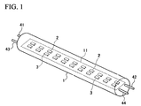
- FIG. 1 is a schematic diagram for illustrating an example of a plant cultivation lamp of the present invention.
- the plant cultivation lamp 1 shown in FIG. 1 is used in a plant cultivation method (Shigyo method) including a step of independently performing a sequence (process) of irradiating a plant with red light and a sequence (process) of irradiating a plant with blue light in fixed time periods (within a certain period of time), and the plant cultivation lamp includes a light irradiation unit 11 and a control unit (not shown) used to control the light irradiation unit.
- a plant cultivation method Shigyo method
- the plant cultivation lamp includes a light irradiation unit 11 and a control unit (not shown) used to control the light irradiation unit.
- irradiation light may include red light, and if the intensity of the red light included in the irradiation light is greater than or equal to 60%, the irradiation light may include light other than red light, such as, for example, blue light.
- the process of irradiating a plant with red light in the Shigyo method allows mixing of the red light with about 30% of blue light in an intensity ratio, and thus it is possible to obtain an effect of enhancing growth of a plant within the allowable range.
- the mixed amount of blue light is more preferably set to be less than or equal to 20% and most preferably set to be 0%.
- An example of the irradiation light intensity ratio in the sequence of irradiating a plant with red light includes 60% of red light, 20% of far infrared light, and 20% of blue light, and the most preferable intensity ratio is 100% of red light.
- the intensity ratio of the irradiation light in the present invention is obtained using the photosynthetic photon flux density (PPFD, unit: ⁇ mol/m 2 s).
- irradiation light may include blue light, and if the intensity of the blue light included in the irradiation light is greater than or equal to 60%, the irradiation light may include light other than blue light, such as, for example, red light.
- the process of irradiating a plant with blue light in the Shigyo method allows mixing of the blue light with 30% of red light based on intensity and it is possible to obtain an effect of promoting growth of a plant within the allowable range.
- the mixed amount of red light is more preferably set to be less than or equal to 20% and most preferably set to be 0%.
- An example of the irradiation light intensity ratio in the sequence of irradiating a plant with blue light includes 60% of blue light, 20% of far infrared light, and 20% of red light, and the most preferable intensity ratio is 100% of blue light.
- the light irradiation unit 11 has a long rectangular shape in planar view and has an outer shape compatible with a customized straight tube fluorescent lamp.
- the light irradiation unit 11 has a plurality of red light emitting elements 2 that emit red light and a plurality of blue light emitting elements 3 that emit blue light.
- the number of red light emitting elements 2 is the same as the number of blue light emitting elements 3.
- the plurality of red light emitting elements 2 and the plurality of blue light emitting elements 3 are each arranged in a line at regular intervals along the longitudinal direction of the light irradiation unit 11.
- the linearly arranged plurality of red light emitting elements 2 and the plurality of blue light emitting elements 3 are disposed approximately in parallel to each other.
- the number of red light emitting elements 2 and the number of blue light emitting elements 3 in the plant cultivation lamp 1 shown in FIG. 1 are the same, but they may be different from each other. Depending on the type of plant to be cultivated, growth of a plant is promoted by making the light emission intensity of red light higher than the light emission intensity of blue light in some cases. In a case of cultivating such a plant, it is preferable to use a plant cultivation lamp 1 where the number of red light emitting elements 2 is increased more than the number of blue light emitting elements 3 included in the light irradiation unit 11. It is possible to make the light emission intensity of red light higher than the light emission intensity of blue light in emitted light from the light irradiation unit 11 by making the number of red light emitting elements 2 higher than the number of blue light emitting elements 3.
- a light irradiation unit in which the light emission intensity of red light and the light emission intensity of blue light are different can be made by adjusting any one of the number of the light emitting element and the light emission intensity of the light emitting element. For example, it can be made by making the number of the red light emitting element and the number of the blue light emitting element the same and making the light emission intensity of the red light emitting element and the light emission intensity of the blue light emitting element different from each other. It can be made by making the ratio of the number of identical red light emitting elements and the number of identical blue light emitting elements corresponding to the ratio of the light emission intensities of red light and blue light.
- a light irradiation unit in which the light emission intensity of red light and the light emission intensity of blue light are different can also be made by adjusting both of the number of the light emitting element and the light emission intensity of the light emitting element.
- the light emission intensity ratio of the red light emitting element 2 to the blue light emitting element 3 (total intensity of red light : total intensity of blue light) is preferably within a range between 2:1 to 9:1, and more preferably within a range between 2:1 to 5:1.
- the light emission intensity of blue light is sufficiently higher than the light emission intensity of red light.
- the light emission intensity of red light in the emitted light from the light irradiation unit 11 can be easily made to be sufficiently higher than the light emission intensity of blue light, which is preferable.
- the electric current value can be easily adjusted when making the value of the intensity ratio of the red light to the blue light suitable for plant cultivation.
- the light emission intensity ratio of the red light emitting element 2 to the blue light emitting element 3 is lower than the above-described range (in a case where the light emission intensity of blue light is too high), there is a concern that it is impossible to obtain a sufficient effect of promoting the growth of a plant, the effect being caused by making the light emission intensity of red light higher than the light emission intensity of blue light.
- the light emission intensity ratio of the red light emitting element 2 to the blue light emitting element 3 is higher than the above-described range, there is a concern that it is impossible to obtain a sufficient effect for promoting the growth of a plant because the light emission intensity of red light is too high.
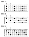
- FIGS 2A to 2D are plan views showing other examples of disposition of red light emitting elements 2 and blue light emitting elements 3 in a light irradiation unit of a plant cultivation lamp, each of which shows a part of the light irradiation unit.
- the ratio of the number of red light emitting elements 2 to the number of blue light emitting elements 3 is set as 2:1.
- the symbol ⁇ indicates red light emitting elements 2 and the symbol ⁇ indicates blue light emitting elements 3.
- irregularity of intensity distribution of emission rarely occurs in a light emission surface, which is preferable.
- the light irradiation unit 11a shown in FIG. 2A there is a row along a direction orthogonal to the longitudinal direction of the light irradiation unit 11a and a line along the longitudinal direction of the light irradiation unit 11a which are formed by the light emitting elements configured to have the plurality of blue light emitting elements 3 and the plurality of red light emitting elements 2.
- the intervals between the light emitting elements adjacent to each other are regularly formed. All the lines configured to have the light emitting elements are linearly arranged with a plurality of units formed of a blue light emitting element 3 and two red light emitting elements 2.
- the rows configured to have the light emitting elements are formed with a blue element group 3a in which a plurality of blue light emitting elements 3 (three in the example shown in FIG. 2A ) are linearly arranged in a row and a red element group 2a in which a plurality of red light emitting elements 2 (three in the example shown in FIG. 2A ) are linearly arranged in two rows.
- the red element group 2a and the blue element group 3a are alternatingly arranged in the longitudinal direction of the light irradiation unit 11a.
- the light irradiation unit 11b shown in FIG. 2B similarly to the light irradiation unit 11a shown in FIG. 2A , there is a row along a direction orthogonal to the longitudinal direction of the light irradiation unit 11b and a line along the longitudinal direction of the light irradiation unit 11b which are formed by the light emitting elements configured to have the plurality of blue light emitting elements 3 and the plurality of red light emitting elements 2. The intervals between the light emitting elements adjacent to each other are regularly formed. Similarly to the light irradiation unit 11a shown in FIG. 2A , a plurality of units formed of a blue light emitting element 3 and two red light emitting elements 2 are arranged in a row.
- the rows configured to have the light emitting elements shown in FIG. 2B include a row linearly arranged with a blue light emitting element 3 between two red light emitting elements 2, a row linearly arranged with a red light emitting element 2 between two blue light emitting elements 3, and a row linearly arranged with three red light emitting elements 2, and these are arranged in the longitudinal direction of the light irradiation unit 11b in this order.
- the light irradiation unit 11c shown in FIG. 2C there are three lines formed along the longitudinal direction of the light irradiation unit 11c by the light emitting elements configured to have the plurality of blue light emitting elements 3 and the plurality of red light emitting elements 2.
- a line in which a plurality of blue light emitting elements 3 are linearly arranged between two lines in which a plurality of red light emitting elements 2 are linearly arranged is disposed.
- the intervals between the light emitting elements adjacent to each other are regularly formed in each line configured to have the light emitting elements.
- the position in a direction orthogonal to the longitudinal direction of the light irradiation unit 11c is disposed such that the center between the blue light emitting elements 3 adjacent to each other is substantially coincident with the center between the red light emitting elements 2.
- each line is linearly arranged in a row with a plurality of units formed of a blue light emitting element 3 and two red light emitting elements 2 similarly to the light irradiation unit 11a shown in FIG. 2A .
- the position in a direction orthogonal to the longitudinal direction of the light irradiation unit 11d is substantially coincident from two lines between which a line located in the center among the three lines is interposed.
- the position in a direction orthogonal to the longitudinal direction of the light irradiation unit 11d is disposed such that the center between the light emitting elements in the line located in the center is substantially coincident with the center between the light emitting elements in the other two lines.
- the combination of the light emitting elements disposed in the other two lines is set to be a blue light emitting element 3 and a red light emitting element 2 or to be two red light emitting elements 2.
- the light irradiation unit of the present invention have mixed color light emitting elements where the red light emitting elements and the blue light emitting elements are equipped in a package. It is preferable that such mixed color light emitting elements have a function of independently controlling the red light emitting elements and the blue light emitting elements.
- the light emission intensity ratio of the red light emitting element to the blue light emitting element included in mixed light emitting elements is preferably within a range between 2:1 to 9:1, and more preferably within a range between 2:1 to 5:1. It is possible to increase the density of light emitting units in the light irradiation unit using such mixed light emitting elements.
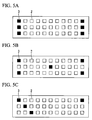
- the light irradiation units shown in FIGS. 3A to 3C are ones in which the ratio of the number of red light emitting elements 2 to the number of blue light emitting elements 3 is set as 3:1, and each of the light irradiation units shown in FIGS. 3A to 3 C corresponds to each of those shown in FIGS. 2A, 2B, 2D .
- Each of FIGS. 3A to 3C show a part of the light irradiation unit, in which all the lines configured to have the light emitting elements are repeatedly arranged with a plurality of units formed of a blue light emitting element 3 and three red light emitting elements 2.
- the light irradiation units shown in FIGS. 4A to 4C are ones in which the ratio of the number of red light emitting elements 2 to the number of blue light emitting elements 3 is set as 5:1, and each of the light irradiation units shown in FIGS. 4A to 4 C corresponds to each of those shown in FIGS. 2A, 2B, 2D .
- Each of FIGS. 4A to 4C show a part of the light irradiation unit, in which all the lines configured to have the light emitting elements are repeatedly arranged with a plurality of units formed of a blue light emitting element 3 and five red light emitting elements 2.
- the light irradiation units shown in FIGS. 5A to 5C are ones in which the ratio of the number of red light emitting elements 2 to the number of blue light emitting elements 3 is set as 5:1, and each of the light irradiation units shown in FIGS. 5A to 5C corresponds to each of those shown in FIGS. 2A, 2B, 2D .
- Each of FIGS. 5A to 5C show a part of the light irradiation unit, in which all the lines configured to have the light emitting elements are repeatedly arranged with a plurality of units formed of a blue light emitting element 3 and nine red light emitting elements 2.
- the red light emitting elements 2 and the blue light emitting elements 3 may be arranged respectively in separate lines, and the lines of the red light emitting elements and the lines of the blue light emitting elements are regularly arranged according to the ratio of the number of the red light emitting elements and the number of the blue light emitting elements, as shown in FIG. 2C .
- red light emitting elements 2 and blue light emitting elements 3 it is possible to use conventionally known ones as red light emitting elements 2 and blue light emitting elements 3.
- a light emitting diode (LED) element it is possible to use a light emitting diode (LED) element, a laser diode (LD) element, electroluminescence (EL) element or the like in which it is easy to select a wavelength and that emits light having a large proportion of light energy of an effective wavelength range.
- the EL element is used as the red light emitting elements 2 and the blue light emitting elements 3
- an organic EL element may be used or an inorganic EL element may be used.
- red light emitted from the red light emitting elements 2 include light having a wavelength between 570 nm and 730 nm and red light having a wavelength between 645 nm and 680 nm as a center wavelength is suitably used.
- blue light emitted from the blue light emitting elements 3 include light having a wavelength between 400 nm and 515 nm and blue light having a wavelength of 450 nm as a center wavelength is suitably used.
- the red light and the blue light can be set to have a predetermined wavelength range by setting the above-described wavelengths as center wavelengths. Examples of the wavelength range include, in a case of blue light, 450 nm ⁇ 30 nm, preferably 450 nm ⁇ 20 nm, more preferably, 450 nm ⁇ 10 nm.
- the light emission intensity of red light and blue light from the light irradiation unit 11 is not particularly limited, but it is preferable to set the light emission intensity ratio of the red light emitting element to the blue light emitting element to be in a range of 1 ⁇ mol/m 2 s to 1000 ⁇ mol/m 2 s, preferably 10 ⁇ mol/m 2 s to 500 ⁇ mol/m 2 s, and particularly preferably 50 ⁇ mol/m 2 s to 250 ⁇ mol/m 2 s by the photosynthetic photon flux density (PPFD).
- PPFD photosynthetic photon flux density
- the light emission intensity of red light and blue light from the light irradiation unit 11 can be controlled such that the amount of electric current supplied to the red light emitting elements 2 or blue light emitting elements 3 is adjusted by the control unit provided in the plant cultivation lamp 1.
- One end of the light irradiation unit 11 in the plant cultivation lamp 1 shown in FIG. 1 is provided with two input terminals 41 and 43 for the red light emitting elements 2 and the other end thereof is provided with two input terminals 42 and 44 for the blue light emitting elements 3.
- a plurality of red light emitting elements 2 is electrically connected to input terminals 41 and 43 for the red light emitting elements 2 via a wire (not shown).
- a plurality of blue light emitting elements 3 is electrically connected to input terminals 42 and 44 for the blue light emitting elements 3 via a wire (not shown).
- the control unit provided in the plant cultivation lamp 1 of the present embodiment independently turns on and off the red light emitting elements 2 and the blue light emitting elements 3 by supplying a predetermined electric current to the red light emitting elements 2 and the blue light emitting elements 3 via the input terminals 41 and 43 for the red light emitting elements 2 or input terminals 42 and 44 for the blue light emitting elements 3.
- control unit is provided with a lamp controller (light emission intensity control means) that controls the light emission intensity ratio of the red light to the blue light emitted from the light irradiation unit 11.
- lamp controller light emission intensity control means
- the lamp controller examples include a lamp controller that controls the light emission intensity ratio of the red light to the blue light omitted from the light irradiation unit 11 by adjusting the amount of electric current supplied to the red light emitting elements 2 or blue light emitting elements 3 and by changing the intensity ratio of part or all of red light emitting elements 2 and/or part or all of blue light emitting elements 3, or a lamp controller that controls the number of red light emitting elements 2 and/or blue light emitting elements 3 to be turned on and controls the light emission intensity ratio of the red light to the blue light emitted from the light irradiation unit 11 by supplying a predetermined electric current to a part of red light emitting elements 2 and/or blue light emitting elements 3.
- the plant cultivation lamp 1 shown in FIG. 1 may be a plant cultivation lamp that emits light in which the light emission intensity of blue light is the same as the light emission intensity of the red light, from the light irradiation unit 11 by supplying an identical electric current to all of the red light emitting elements 2 and all of the blue light emitting elements 3 using the lamp controller.
- the plant cultivation lamp 1 may not be provided with the lamp controller.
- the plant cultivation lamp 1 shown in FIG. 1 may be a plant cultivation lamp that emits light in which the light emission intensity ratio of the red light to the blue light is 2:1 (red light : blue light), from the light irradiation unit 11 by setting the light emission intensity of the blue light emitting elements 3 to be half of the light emission intensity of the red light emitting elements 2 using the lamp controller, for example.
- a used plant cultivation lamp may output emitted light in which the light emission intensity ratio of the red light to the blue light is 2:1 (red light : blue light), from the light irradiation unit by supplying an identical electric current to all of the red light emitting elements 2 and all of the blue light emitting elements 3 using the lamp controller, for example.
- the plant cultivation lamp since an identical electric current is supplied to all of the red light emitting elements 2 and all of the blue light emitting elements 3, the plant cultivation lamp may not be provided with the lamp controller.
- the lamps for plant cultivation 1 shown in FIGS. 2A to 2D may be lamps for plant cultivation that emit emitted light in which the light emission intensity ratio of red light to blue light is 4:1 (red light: blue light), from the light irradiation unit by setting the light emission intensity of the blue light emitting elements 3 to be half of the light emission intensity of the red light emitting elements 2 using the lamp controller, for example.
- the light emission intensity ratio of the red light to the blue light from the light irradiation unit 11 is preferably within a range between 2:1 to 9:1, and more preferably within a range between 2:1 to 5:1.
- the light emission intensity ratio of the red light to the blue light is within the above-described range, it is possible to obtain a sufficient effect of promoting the growth of a plant, the effect being caused by making the light emission intensity of red light higher than the light emission intensity of blue light.
- the light emission intensity ratio of red light to blue light is lower than the above-described range, there is a concern that it is impossible to obtain a sufficient effect of promoting the growth of a plant, the effect being caused by making the light emission intensity of red light higher than the light emission intensity of blue light because it is impossible to obtain a sufficient difference between the light emission intensity of the red light and the light emission intensity of the blue light.
- the light emission intensity ratio of red light to blue light is higher than the above-described range, there is a concern that it is impossible to obtain sufficient effect of promoting the growth of a plant because the light emission intensity of red light is too high.
- the plant cultivation method of the present embodiment includes a step of independently performing a sequence of irradiating a plant with red light (hereinafter, referred to as “red light irradiation step) and a sequence of irradiating a plant with blue light (hereinafter, referred to as “blue light irradiation step) within a certain period of time (Shigyo method).
- red light irradiation step a sequence of irradiating a plant with red light
- blue light irradiation step a sequence of irradiating a plant with blue light
- the "certain period of time” meansan arbitrary period of time during plant cultivation.
- the arbitrary period is the full length of the whole cultivation period at longest.
- the shortest period can be arbitrarily set as long as the present invention exhibits an effect.
- the unit of the length of time is between 3 hours and 48 hours.
- flashing irradiation with a high frequency of greater than or equal to 1 Hz is not included in the "certain period of time" of the present invention.
- the term "independently” means that there is a red light irradiation step and a blue light irradiation step separately within the period described above.
- At least one process of the red light irradiation step and at least one process of the blue light irradiation step are included within the period described above.
- the red light irradiation step and the blue light irradiation step may be alternatingly performed in a continuous manner or may be discontinuously repeated by having a sequence of simultaneously irradiating a plant with red light and blue light or a sequence of suspending light irradiation on a plant, each sequence being interposed between both steps.
- the plant cultivation method according to the present invention can start or finish at an arbitrary timing and can be applied for a length of arbitrary time.
- Plants cultivated using the plant cultivation method according to the present invention are not particularly limited, and examples thereof include vegetables, potatoes, mushrooms, fruits, pulses, grains, nuts, algae, ornamental plants, and mosses.
- the Shigyo method is performed using the plant cultivation lamp 1 of the present embodiment, it is possible to easily irradiate a plant to be grown with optimum artificial light thereby obtaining an excellent effect of promoting the growth of a plant.
- the control unit is provided with a lamp controller (light emission intensity control means) that controls the light emission intensity ratio of red light to blue light emitted from the light irradiation unit 11, as the plant cultivation lamp 1.
- the plant cultivation lamp 1 of the present embodiment includes a control unit that independently turns on and off the red light emitting elements 2 and the blue light emitting elements 3. Therefore, it is possible to simultaneously or alternatingly irradiate a plant with red light and blue light or to change the duration of the irradiation with red light and blue light depending on the plant to be grown so as to obtain a sufficient effect of promoting the growth of the plant using the Shigyo method, thereby obtaining an excellent effect of promoting the growth of the plant.
- the plant cultivation lamp 1 of the present embodiment includes the light irradiation unit having the red light emitting elements 2 and the blue light emitting elements 3. Therefore, it is possible to easily secure a space used to dispose the irradiation means and to reduce the deviation between the direction from which a plant is irradiated with red light and the direction from which a plant is irradiated with blue light in comparison with a case where two types of irradiation means, a means of irradiating red light and a means of irradiating blue light, are disposed in the lamp.
- control unit of the plant cultivation lamp 1 of the present embodiment includes the lamp controller used to control the light emission intensity ratio of red light to blue light emitted from the light irradiation unit 11, it is possible to easily change the intensity ratio of red light to blue light, thereby easily providing an optimum intensity ratio to a plant to be grown.
- the plant cultivation lamp 1 of the present embodiment includes a light irradiation unit 11 having a long rectangular shape in planar view. Therefore, it is possible to substitute the light irradiation unit with lighting equipment such as a straight tube fluorescent lamp of the related art, and the light irradiation unit thereby may be easily installed in a position in which lighting equipment of the related art is installed.
- the light irradiation unit have a red conversion means electrically connected to red light emitting elements and a blue conversion means electrically connected to blue light emitting elements.
- the red conversion means outputs AC power, which is input, by converting the AC power into DC power and has a function used to control an output electric current which is supplied to the red light emitting element.
- the blue conversion means outputs AC power, which is input, by converting the AC power into DC power and has a function used to control an output electric current which is supplied to the blue light emitting elements.
- the light irradiation unit includes the red conversion means and the blue conversion means
- the light irradiation unit includes the red conversion means and the conversion means for blue, it is possible to effectively utilize the space compared to a case where conversion means for converting the AC power into the DC power is separately installed from the plant cultivation lamp, which is desirable.
- the light irradiation unit has a long rectangular shape in planar view and includes red conversion means and conversion means for blue
- one end of the light irradiation unit be provided with two input terminals for red light emitting elements electrically connected to the red conversion means and the other end be provided with two input terminals for the blue light emitting elements electrically connected to the conversion means for blue.
- a plurality of lamps for plant cultivation are simultaneously used.
- a light dimmer system that can control the light emission intensity of the plurality of lamps for plant cultivation.
- the light dimmer systems include a light dimmer system that separately controls the power supplied to each plant cultivation lamp.
- the present invention is not limited to the above-described embodiment.
- control unit includes light emission intensity control means as the plant cultivation lamp of the present invention
- the control unit may not include the lamp controller.
- leaf lettuce (variety: Summer surge) was used as an objective plant to observe a growth state.
- 6 seeds of the leaf lettuce plants were sown in a peat plate used for growing at regular intervals and were germinated under a fluorescent light (12 hour day length). All the test groups were placed under an identical light environment for 3 days from sowing until germination.
- the leaf lettuce plants were placed in meteorological instruments under different light environments of Examples 1 to 3, and then were grown for 24 hours. All the environments within the meteorological instruments used in Examples 1 to 3 were set to identical conditions at 25°C to 27°C of the atmospheric temperature and 60% of humidity, except for the light irradiation condition.
- Example 1 a plant cultivation lamp that includes a light irradiation unit having red light emitting elements formed of 240 red LEDs (center wavelength: 660 nm, HRP-350F made by SHOWA DENKO K.K.) and having blue light emitting elements formed of 240 blue LEDs (center wavelength: 450 nm, GM2LR450G made by SHOWA DENKO K.K.), and a control unit that controls the light irradiation unit to independently turn on and off the red light emitting elements and the blue light emitting elements was used.
- a light irradiation unit having red light emitting elements formed of 240 red LEDs (center wavelength: 660 nm, HRP-350F made by SHOWA DENKO K.K.) and having blue light emitting elements formed of 240 blue LEDs (center wavelength: 450 nm, GM2LR450G made by SHOWA DENKO K.K.)
- a control unit that controls the light irradiation unit to independently turn on
- red light emitting elements and blue light emitting elements are arranged as shown in FIG. 1 .
- the photosynthetic photon flux density (PPFD) as a light emission intensity of red light from the light irradiation unit was set as 150 ⁇ mol/m 2 s in total and the photosynthetic photon flux density (PPFD) as a light emission intensity of blue light from the light irradiation unit was set as 150 ⁇ mol/m 2 s in total (light emission intensity ratio of red light to blue light is 1:1).
- a red light irradiation step of irradiating a plant only with red light and a blue light irradiation step of irradiating a plant only with blue light were separately performed in a continuous manner for 1 day, being 12 hours per each color. There was no time where irradiation was not performed using any light.
- Example 2 The same test as Example 1 was performed except that a plant cultivation lamp was used that includes a light irradiation unit having red light emitting elements formed of 320 red LEDs (center wavelength: 660 nm, HRP-350F made by SHOWA DENKO K.K.) and having blue light emitting elements formed of 160 blue LEDs (center wavelength: 450 nm, GM2LR450G made by SHOWA DENKO K.K.).
- a plant cultivation lamp includes a light irradiation unit having red light emitting elements formed of 320 red LEDs (center wavelength: 660 nm, HRP-350F made by SHOWA DENKO K.K.) and having blue light emitting elements formed of 160 blue LEDs (center wavelength: 450 nm, GM2LR450G made by SHOWA DENKO K.K.).
- red light emitting elements and blue light emitting elements are arranged as shown in FIG. 2A .
- the photosynthetic photon flux density (PPFD) of red light from the light irradiation unit was set as 200 ⁇ mol/m 2 s and the photosynthetic photon flux density (PPFD) of blue light from the light irradiation unit was set as 100 ⁇ mol/m 2 s (light emission intensity ratio of red light to blue light is 2:1).
- Example 2 The same test as Example 1 was performed except for the use of the same light irradiation unit as that in Example 2 and a plant cultivation lamp that has a control unit provided with a lamp controller (light emission intensity control means) which can be used to change the light emission intensity ratio of red light to blue light by the lamp controller.
- a lamp controller light emission intensity control means
- the photosynthetic photon flux density (PPFD) of red light as the light emission intensity of red light from the light irradiation unit was set to 225 ⁇ mol/m 2 s and the photosynthetic photon flux density (PPFD) of blue light from the light irradiation unit was set to 75 ⁇ mol/m 2 s (light emission intensity ratio of red light to blue light is 3:1).
- Example 2 The same test as Example 1 was performed except for the use of the same light irradiation unit as that in Example 2 and a plant cultivation lamp that has a control unit provided with a lamp controller (light emission intensity control means) which can be used to change the light emission intensity ratio of red light to blue light by the lamp controller.
- a lamp controller light emission intensity control means
- the photosynthetic photon flux density (PPFD) of red light as the light emission intensity of red light from the light irradiation unit was set to 250 ⁇ mol/m 2 s and the photosynthetic photon flux density (PPFD) of blue light from the light irradiation unit was set to 50 ⁇ mol/m 2 s (light emission intensity ratio of red light to blue light is 5:1).
- Example 1 The same test as Example 1 was performed except for the use of a light irradiation unit as shown in FIG. 5B , in which the ratio of the number of the red light emitting elements and the number of the blue light emitting elements is 9:1.
- the photosynthetic photon flux density (PPFD) of red light from the light irradiation unit was set as 270 ⁇ mol/m 2 s and the photosynthetic photon flux density (PPFD) of blue light from the light irradiation unit was set as 30 ⁇ mol/m 2 s (light emission intensity ratio of red light to blue light is 9:1).
- the light emission intensity ratio of red light to blue light was set as 1:1 and light including the red light and the blue light was turned on for 12 hours and turned off for 12 hours during a day using a lamp in which the red light and the blue light were not separated so as to be under the same light conditions as Example 1.
- Example 1 As to the leaf lettuces grown for 24 days in Examples 1 to 3 and Comparative Example, the weight of above-ground part (above-ground part fresh weight) was measured to obtain a mass ratio by setting the mass ratio of Example 1 as 100%. The result is shown in Table 1. TABLE 1 INTENSITY RATIO OF RED LIGHT TO BLUE LIGHT FRESH WEIGHT RATIO OF ABOVE-GROUND PART (%) EXAMPLE1 1:1 100 EXAMPLE2 2:1 140 EXAMPLE3 3:1 160 EXAMPLE4 5:1 145 EXAMPLE5 9:1 110 COMPARATIVE EXAMPLE 70
- Example 2 in which a plant was irradiated with artificial light having the light emission intensity ratio of the red light to blue light of 2:1 exhibits a high effect of promoting growth of a plant in comparison with Example 1 in which a plant was irradiated with artificial light having a light emission intensity ratio of red light to blue light of 1:1.
- Example 3 in which a plant was irradiated with artificial light having a light emission intensity ratio of red light to blue light of 3:1 exhibits a high effect of promoting growth of a plant in comparison with Example 2.
- Example 4 in which a plant was irradiated with artificial light having a light emission intensity ratio of red light to blue light of 5:1 exhibits a high effect of promoting growth of a plant in comparison with Example 2, and Example 4 exhibits a low effect of promoting growth of a plant in comparison with Example 3.
- Example 5 in which a plant was irradiated with artificial light having a light emission intensity ratio of red light to blue light of 9:1 exhibits a high effect of promoting growth of a plant in comparison with Example 1, and Example 5 exhibits a low effect of promoting growth of a plant in comparison with Examples 2 to 4.
- Comparative Example in which a plant was irradiated with light including the red light and the blue light exhibits a low effect for promoting growth of a plant in comparison with Example 1 because the above-ground part fresh weight ratio in Comparative Example is 70%.
Landscapes
- Life Sciences & Earth Sciences (AREA)
- Botany (AREA)
- Environmental Sciences (AREA)
- Biodiversity & Conservation Biology (AREA)
- Ecology (AREA)
- Forests & Forestry (AREA)
- Developmental Biology & Embryology (AREA)
- Cultivation Of Plants (AREA)
Claims (9)
- Pflanzenkultivierungslampe, welche umfasst:eine Lichtstrahlungseinheit, die ein oder mehrere rotes Licht emittierende Rotlichtemissionselemente und ein oder mehrere blaues Licht emittierende Blaulichtemissionselemente umfasst; undeine Kontrolleinheit, welche die Lichtstrahlungseinheit dahingehend kontrolliert, dass die Rotlichtemissionselemente und die Blaulichtemissionselemente unabhängig voneinander ein- und ausgeschaltet werden, so dass abwechselnd Rotlichtbestrahlung zwischen 3 Stunden und 48 Stunden und Blaulichtbestrahlung zwischen 3 Stunden und 48 Stunden auf kontinuierliche Weise durchgeführt wird.
- Pflanzenkultivierungslampe nach Anspruch 1,
wobei die Lichtstrahlungseinheit Mischfarbenlichtemissionselemente umfasst, wobei die Rotlichtemissionselemente und die Blaulichtemissionselemente mit einer identischen Einheit ausgestattet sind. - Pflanzenkultivierungslampe nach Anspruch 1 oder 2,
wobei das Lichtemissionsintensitätsverhältnis des Rotlichtemissionselements zu dem Blaulichtemissionselement im Bereich zwischen 2:1 und 9:1 liegt. - Pflanzenkultivierungslampe nach einem der Ansprüche 1 bis 3,
wobei die Lichtstrahlungseinheit eine Vielzahl von identischen Rotlichtemissionselementen und eine Vielzahl von identischen Blaulichtemissionselementen enthält,
wobei das Verhältnis der Anzahl der Rotlichtemissions-elemente zu der Anzahl der Blaulichtemissionselemente im Bereich von 2:1 bis 9:1 liegt,
wobei die Rotlichtemissionselemente und die Blaulichtemissionselemente so angeordnet sind, dass sie gleichmäßig gemischt sind. - Pflanzenkultivierungslampe nach einem der Ansprüche 1 bis 4,
wobei die Kontrolleinheit Lichtemissionsintensitätskontrollmittel zum Kontrollieren des Lichtemissionsintensitätsverhältnisses von rotem Licht zu blauem Licht, das von der Lichtstrahlungseinheit emittiert wird, umfasst. - Pflanzenkultivierungslampe nach einem der Ansprüche 1 bis 5,
wobei die Lichtstrahlungseinheit eine lange rechtwinklige Form in der Draufsicht hat und eine äußere Form aufweist, die mit einer angepassten Geradrohrfluoreszenzlampe kompatibel ist. - Pflanzenkultivierungslampe nach einem der Ansprüche 1 bis 6,
wobei die Lichtstrahlungseinheit Rotkonversionsmittel für Rot enthält, die mit den Rotlichtemissionselementen elektrisch verbunden sind, und Konversionsmittel für blaues Licht enthält, die mit den Blaulichtemissionselementen elektrisch verbunden sind,
wobei die Rotkonversionsmittel für Rot von Wechselstrom umgewandelten Gleichstrom erzeugt und die Funktion hat, den ausströmenden elektrischen Strom, der dem Rotlichtemissionselement zugeführt wird, zu kontrollieren, und
wobei die Konversionsmittel für Blau von Wechselstrom umgewandelten Gleichstrom erzeugen und die Funktion haben, den ausströmenden elektrischen Strom, der den Blaulichtemissionselementen zugeführt wird, zu kontrollieren. - Pflanzenkultivierungslampe nach Anspruch 7,
wobei die Lichtstrahlungseinheit eine lange rechtwinklige Form in der Draufsicht aufweist und zwei Eingangsanschlüsse für die Rotlichtemissionselemente, die an einem Ende mit den Rotkonversionsmitteln elektrisch verbunden sind, und zwei Einlassanschlüsse für die Blaulichtemissionselemente umfasst, die mit den Konversionsmitteln für Blau am anderen Ende elektrisch verbunden sind. - Pflanzenkultivierungsverfahren unter Einsatz einer Pflanzenkultivierungslampe nach einem der Ansprüche 1 bis 8, welches umfasst:eine Sequenz der Belichtung einer Pflanze mit rotem Licht; undeine Sequenz der Belichtung einer Pflanze mit blauem Licht,wobei die Sequenzen unabhängig voneinander und abwechselnd innerhalb eines bestimmten Zeitraums durchgeführt werden, wobei die Belichtung mit rotem Licht zwischen 3 Stunden und 48 Stunden kontinuierlich durchgeführt wird und die Belichtung mit blauem Licht zwischen 3 Stunden und 48 Stunden kontinuierlich durchgeführt wird.
Applications Claiming Priority (2)
| Application Number | Priority Date | Filing Date | Title |
|---|---|---|---|
| JP2013019930 | 2013-02-04 | ||
| JP2014017586A JP5779678B2 (ja) | 2013-02-04 | 2014-01-31 | 植物栽培用ランプおよびこれを用いた植物栽培方法 |
Publications (2)
| Publication Number | Publication Date |
|---|---|
| EP2761995A1 EP2761995A1 (de) | 2014-08-06 |
| EP2761995B1 true EP2761995B1 (de) | 2016-11-02 |
Family
ID=50030148
Family Applications (1)
| Application Number | Title | Priority Date | Filing Date |
|---|---|---|---|
| EP14153619.3A Not-in-force EP2761995B1 (de) | 2013-02-04 | 2014-02-03 | Pflanzenzuchtlampe und Pflanzenzuchtverfahren damit |
Country Status (3)
| Country | Link |
|---|---|
| US (1) | US20140215917A1 (de) |
| EP (1) | EP2761995B1 (de) |
| JP (1) | JP5779678B2 (de) |
Families Citing this family (13)
| Publication number | Priority date | Publication date | Assignee | Title |
|---|---|---|---|---|
| JP6484083B2 (ja) * | 2015-03-31 | 2019-03-13 | ウシオ電機株式会社 | 植物育成用照明装置並びに植物水耕栽培装置および植物水耕栽培方法 |
| ITUB20152355A1 (it) * | 2015-07-21 | 2017-01-21 | Osram Spa | Dispositivo di illuminazione, ad esempio per l'illuminazione di serre, e corrispondente procedimento di impiego |
| USD795737S1 (en) | 2015-11-09 | 2017-08-29 | LED Habitats LLC | Grow light apparatus |
| JP6800729B2 (ja) * | 2016-12-13 | 2020-12-16 | 昭和電工株式会社 | 植物栽培用照明装置及び連結式植物栽培用照明装置並びに植物栽培装置 |
| NL2018324B1 (nl) | 2017-02-07 | 2018-09-03 | Priva Holding B V | Werkwijze en inrichting voor het telen van een gewas |
| US11266076B2 (en) | 2018-01-31 | 2022-03-08 | Fluence Bioengineering, Inc. | Lighting device and a method of distributing light radiation sources |
| JP7185126B2 (ja) * | 2018-03-14 | 2022-12-07 | 日亜化学工業株式会社 | 照明装置及び植物栽培方法 |
| JP2020018210A (ja) * | 2018-07-31 | 2020-02-06 | 株式会社リコー | 栽培システム |
| CN109099366A (zh) * | 2018-08-27 | 2018-12-28 | 深圳福凯半导体技术股份有限公司 | 植物生长灯 |
| WO2020153935A1 (en) * | 2019-01-21 | 2020-07-30 | Growor, Inc. | Devices for an optimized, high-intensity, horticultural, led luminaire having a regulated photosynthetic photon flux density |
| JP7431438B2 (ja) * | 2020-02-07 | 2024-02-15 | 国立大学法人宇都宮大学 | 緑色葉物野菜の葉の厚さ及び大きさの制御方法 |
| US11707022B2 (en) * | 2020-02-14 | 2023-07-25 | Seoul Viosys Co., Ltd. | Light device for plant cultivation |
| USD994184S1 (en) * | 2023-01-10 | 2023-08-01 | Qianhai Siruituo Network Technology (Shenzhen) Co., Ltd. | Grow light for plants |
Citations (1)
| Publication number | Priority date | Publication date | Assignee | Title |
|---|---|---|---|---|
| JPH08103167A (ja) * | 1994-10-05 | 1996-04-23 | Kensei Okamoto | 植物栽培用光源 |
Family Cites Families (15)
| Publication number | Priority date | Publication date | Assignee | Title |
|---|---|---|---|---|
| US3930335A (en) * | 1973-04-02 | 1976-01-06 | Controlled Environment Systems, Inc. | Plant growth system |
| JPH06276858A (ja) | 1993-03-31 | 1994-10-04 | Iwasaki Electric Co Ltd | 閉鎖空間の植物の照明装置 |
| JP4081648B2 (ja) * | 2001-11-28 | 2008-04-30 | 東芝ライテック株式会社 | 電照装置 |
| EP1626620B1 (de) * | 2003-05-23 | 2010-04-21 | Fotofresh Limited | Methoden zur änderung des gehalts an phytochechemischen verbindungen in pflanzenzellen umfassend die anwendung von licht der wellenlänge von 400-700 nm sowie dazugehörende apparat |
| JP2010004869A (ja) * | 2008-05-28 | 2010-01-14 | Mitsubishi Chemicals Corp | 生物の育成装置及び育成方法 |
| KR101422364B1 (ko) * | 2009-08-07 | 2014-07-22 | 쇼와 덴코 가부시키가이샤 | 식물 육성용의 다색 발광 다이오드 램프, 조명 장치 및 식물 육성 방법 |
| CN101852368B (zh) * | 2010-01-28 | 2011-07-27 | 杭州汉徽光电科技有限公司 | 一种用于兰科植物组培的led混光灯具 |
| US8523385B2 (en) * | 2010-08-20 | 2013-09-03 | DiCon Fibêroptics Inc. | Compact high brightness LED grow light apparatus, using an extended point source LED array with light emitting diodes |
| JP2012059908A (ja) * | 2010-09-09 | 2012-03-22 | Takeshi Yamaoka | 光の三原色併設型発光ダイオード |
| JP6012928B2 (ja) * | 2011-03-01 | 2016-10-25 | 公立大学法人大阪府立大学 | 植物栽培方法及び体内時計最適化植物栽培装置 |
| WO2013027198A1 (en) * | 2011-08-21 | 2013-02-28 | D. Led. Technologies Ltd. | Light signaling system for plant behavior manipulation |
| US9137874B2 (en) * | 2011-12-02 | 2015-09-15 | Biological Illumination, Llc | Illumination and grow light system and associated methods |
| US10257988B2 (en) * | 2011-12-02 | 2019-04-16 | Biological Illumination, Llc | Illumination and grow light system and associated methods |
| JP3180774U (ja) * | 2012-10-24 | 2013-01-10 | 昭和電工株式会社 | 植物栽培用ledランプ及び植物栽培用ledランプシステム |
| EP2982238B1 (de) * | 2013-04-03 | 2020-06-17 | Fuji Seiko Co., Ltd. | Luftemissionsvorrichtung zum züchten von pflanzen |
-
2014
- 2014-01-31 JP JP2014017586A patent/JP5779678B2/ja not_active Expired - Fee Related
- 2014-02-03 US US14/171,089 patent/US20140215917A1/en not_active Abandoned
- 2014-02-03 EP EP14153619.3A patent/EP2761995B1/de not_active Not-in-force
Patent Citations (1)
| Publication number | Priority date | Publication date | Assignee | Title |
|---|---|---|---|---|
| JPH08103167A (ja) * | 1994-10-05 | 1996-04-23 | Kensei Okamoto | 植物栽培用光源 |
Also Published As
| Publication number | Publication date |
|---|---|
| JP2014166179A (ja) | 2014-09-11 |
| US20140215917A1 (en) | 2014-08-07 |
| JP5779678B2 (ja) | 2015-09-16 |
| EP2761995A1 (de) | 2014-08-06 |
Similar Documents
| Publication | Publication Date | Title |
|---|---|---|
| EP2761995B1 (de) | Pflanzenzuchtlampe und Pflanzenzuchtverfahren damit | |
| EP2946654B1 (de) | Verfahren zur kultivierung von obst oder gemüse | |
| JP5779604B2 (ja) | 植物栽培方法 | |
| EP3075230A1 (de) | Pflanzenwachstums-beleuchtungsvorrichtung, hydrophonische kultivierungsvorrichtung und hydrophonisches kultivierungsverfahren | |
| JP5723900B2 (ja) | 植物栽培方法 | |
| KR102285707B1 (ko) | 식물 재배용 광원을 이용한 식물 재배 장치 및 식물 재배 방법 | |
| JP5724002B2 (ja) | 植物栽培方法 | |
| EP2761992B1 (de) | Verfahren zum Züchten von Pflanzen | |
| JP5724003B2 (ja) | 植物栽培方法 | |
| JP5723901B2 (ja) | 植物栽培方法 | |
| JP5723904B2 (ja) | 植物栽培方法 | |
| JP6005787B2 (ja) | 果菜類の栽培方法 | |
| JP5723902B2 (ja) | 植物栽培方法 |
Legal Events
| Date | Code | Title | Description |
|---|---|---|---|
| PUAI | Public reference made under article 153(3) epc to a published international application that has entered the european phase |
Free format text: ORIGINAL CODE: 0009012 |
|
| 17P | Request for examination filed |
Effective date: 20140228 |
|
| AK | Designated contracting states |
Kind code of ref document: A1 Designated state(s): AL AT BE BG CH CY CZ DE DK EE ES FI FR GB GR HR HU IE IS IT LI LT LU LV MC MK MT NL NO PL PT RO RS SE SI SK SM TR |
|
| AX | Request for extension of the european patent |
Extension state: BA ME |
|
| RBV | Designated contracting states (corrected) |
Designated state(s): AL AT BE BG CH CY CZ DE DK EE ES FI FR GB GR HR HU IE IS IT LI LT LU LV MC MK MT NL NO PL PT RO RS SE SI SK SM TR |
|
| 17Q | First examination report despatched |
Effective date: 20150619 |
|
| GRAP | Despatch of communication of intention to grant a patent |
Free format text: ORIGINAL CODE: EPIDOSNIGR1 |
|
| INTG | Intention to grant announced |
Effective date: 20160512 |
|
| GRAS | Grant fee paid |
Free format text: ORIGINAL CODE: EPIDOSNIGR3 |
|
| GRAA | (expected) grant |
Free format text: ORIGINAL CODE: 0009210 |
|
| AK | Designated contracting states |
Kind code of ref document: B1 Designated state(s): AL AT BE BG CH CY CZ DE DK EE ES FI FR GB GR HR HU IE IS IT LI LT LU LV MC MK MT NL NO PL PT RO RS SE SI SK SM TR |
|
| REG | Reference to a national code |
Ref country code: GB Ref legal event code: FG4D |
|
| REG | Reference to a national code |
Ref country code: AT Ref legal event code: REF Ref document number: 840828 Country of ref document: AT Kind code of ref document: T Effective date: 20161115 Ref country code: CH Ref legal event code: EP |
|
| REG | Reference to a national code |
Ref country code: IE Ref legal event code: FG4D |
|
| REG | Reference to a national code |
Ref country code: DE Ref legal event code: R096 Ref document number: 602014004527 Country of ref document: DE |
|
| REG | Reference to a national code |
Ref country code: NL Ref legal event code: FP |
|
| PG25 | Lapsed in a contracting state [announced via postgrant information from national office to epo] |
Ref country code: LV Free format text: LAPSE BECAUSE OF FAILURE TO SUBMIT A TRANSLATION OF THE DESCRIPTION OR TO PAY THE FEE WITHIN THE PRESCRIBED TIME-LIMIT Effective date: 20161102 |
|
| REG | Reference to a national code |
Ref country code: LT Ref legal event code: MG4D |
|
| REG | Reference to a national code |
Ref country code: AT Ref legal event code: MK05 Ref document number: 840828 Country of ref document: AT Kind code of ref document: T Effective date: 20161102 |
|
| PG25 | Lapsed in a contracting state [announced via postgrant information from national office to epo] |
Ref country code: NO Free format text: LAPSE BECAUSE OF FAILURE TO SUBMIT A TRANSLATION OF THE DESCRIPTION OR TO PAY THE FEE WITHIN THE PRESCRIBED TIME-LIMIT Effective date: 20170202 Ref country code: SE Free format text: LAPSE BECAUSE OF FAILURE TO SUBMIT A TRANSLATION OF THE DESCRIPTION OR TO PAY THE FEE WITHIN THE PRESCRIBED TIME-LIMIT Effective date: 20161102 Ref country code: LT Free format text: LAPSE BECAUSE OF FAILURE TO SUBMIT A TRANSLATION OF THE DESCRIPTION OR TO PAY THE FEE WITHIN THE PRESCRIBED TIME-LIMIT Effective date: 20161102 Ref country code: GR Free format text: LAPSE BECAUSE OF FAILURE TO SUBMIT A TRANSLATION OF THE DESCRIPTION OR TO PAY THE FEE WITHIN THE PRESCRIBED TIME-LIMIT Effective date: 20170203 |
|
| PG25 | Lapsed in a contracting state [announced via postgrant information from national office to epo] |
Ref country code: PT Free format text: LAPSE BECAUSE OF FAILURE TO SUBMIT A TRANSLATION OF THE DESCRIPTION OR TO PAY THE FEE WITHIN THE PRESCRIBED TIME-LIMIT Effective date: 20170302 Ref country code: HR Free format text: LAPSE BECAUSE OF FAILURE TO SUBMIT A TRANSLATION OF THE DESCRIPTION OR TO PAY THE FEE WITHIN THE PRESCRIBED TIME-LIMIT Effective date: 20161102 Ref country code: ES Free format text: LAPSE BECAUSE OF FAILURE TO SUBMIT A TRANSLATION OF THE DESCRIPTION OR TO PAY THE FEE WITHIN THE PRESCRIBED TIME-LIMIT Effective date: 20161102 Ref country code: IS Free format text: LAPSE BECAUSE OF FAILURE TO SUBMIT A TRANSLATION OF THE DESCRIPTION OR TO PAY THE FEE WITHIN THE PRESCRIBED TIME-LIMIT Effective date: 20170302 Ref country code: BE Free format text: LAPSE BECAUSE OF NON-PAYMENT OF DUE FEES Effective date: 20170228 Ref country code: AT Free format text: LAPSE BECAUSE OF FAILURE TO SUBMIT A TRANSLATION OF THE DESCRIPTION OR TO PAY THE FEE WITHIN THE PRESCRIBED TIME-LIMIT Effective date: 20161102 Ref country code: RS Free format text: LAPSE BECAUSE OF FAILURE TO SUBMIT A TRANSLATION OF THE DESCRIPTION OR TO PAY THE FEE WITHIN THE PRESCRIBED TIME-LIMIT Effective date: 20161102 Ref country code: PL Free format text: LAPSE BECAUSE OF FAILURE TO SUBMIT A TRANSLATION OF THE DESCRIPTION OR TO PAY THE FEE WITHIN THE PRESCRIBED TIME-LIMIT Effective date: 20161102 Ref country code: FI Free format text: LAPSE BECAUSE OF FAILURE TO SUBMIT A TRANSLATION OF THE DESCRIPTION OR TO PAY THE FEE WITHIN THE PRESCRIBED TIME-LIMIT Effective date: 20161102 |
|
| PG25 | Lapsed in a contracting state [announced via postgrant information from national office to epo] |
Ref country code: RO Free format text: LAPSE BECAUSE OF FAILURE TO SUBMIT A TRANSLATION OF THE DESCRIPTION OR TO PAY THE FEE WITHIN THE PRESCRIBED TIME-LIMIT Effective date: 20161102 Ref country code: SK Free format text: LAPSE BECAUSE OF FAILURE TO SUBMIT A TRANSLATION OF THE DESCRIPTION OR TO PAY THE FEE WITHIN THE PRESCRIBED TIME-LIMIT Effective date: 20161102 Ref country code: DK Free format text: LAPSE BECAUSE OF FAILURE TO SUBMIT A TRANSLATION OF THE DESCRIPTION OR TO PAY THE FEE WITHIN THE PRESCRIBED TIME-LIMIT Effective date: 20161102 Ref country code: CZ Free format text: LAPSE BECAUSE OF FAILURE TO SUBMIT A TRANSLATION OF THE DESCRIPTION OR TO PAY THE FEE WITHIN THE PRESCRIBED TIME-LIMIT Effective date: 20161102 Ref country code: EE Free format text: LAPSE BECAUSE OF FAILURE TO SUBMIT A TRANSLATION OF THE DESCRIPTION OR TO PAY THE FEE WITHIN THE PRESCRIBED TIME-LIMIT Effective date: 20161102 |
|
| REG | Reference to a national code |
Ref country code: DE Ref legal event code: R097 Ref document number: 602014004527 Country of ref document: DE |
|
| PG25 | Lapsed in a contracting state [announced via postgrant information from national office to epo] |
Ref country code: IT Free format text: LAPSE BECAUSE OF FAILURE TO SUBMIT A TRANSLATION OF THE DESCRIPTION OR TO PAY THE FEE WITHIN THE PRESCRIBED TIME-LIMIT Effective date: 20161102 Ref country code: BE Free format text: LAPSE BECAUSE OF FAILURE TO SUBMIT A TRANSLATION OF THE DESCRIPTION OR TO PAY THE FEE WITHIN THE PRESCRIBED TIME-LIMIT Effective date: 20161102 Ref country code: SM Free format text: LAPSE BECAUSE OF FAILURE TO SUBMIT A TRANSLATION OF THE DESCRIPTION OR TO PAY THE FEE WITHIN THE PRESCRIBED TIME-LIMIT Effective date: 20161102 Ref country code: BG Free format text: LAPSE BECAUSE OF FAILURE TO SUBMIT A TRANSLATION OF THE DESCRIPTION OR TO PAY THE FEE WITHIN THE PRESCRIBED TIME-LIMIT Effective date: 20170202 |
|
| PLBE | No opposition filed within time limit |
Free format text: ORIGINAL CODE: 0009261 |
|
| STAA | Information on the status of an ep patent application or granted ep patent |
Free format text: STATUS: NO OPPOSITION FILED WITHIN TIME LIMIT |
|
| PG25 | Lapsed in a contracting state [announced via postgrant information from national office to epo] |
Ref country code: MC Free format text: LAPSE BECAUSE OF FAILURE TO SUBMIT A TRANSLATION OF THE DESCRIPTION OR TO PAY THE FEE WITHIN THE PRESCRIBED TIME-LIMIT Effective date: 20161102 |
|
| REG | Reference to a national code |
Ref country code: CH Ref legal event code: PL |
|
| 26N | No opposition filed |
Effective date: 20170803 |
|
| PG25 | Lapsed in a contracting state [announced via postgrant information from national office to epo] |
Ref country code: CH Free format text: LAPSE BECAUSE OF NON-PAYMENT OF DUE FEES Effective date: 20170228 Ref country code: LI Free format text: LAPSE BECAUSE OF NON-PAYMENT OF DUE FEES Effective date: 20170228 |
|
| REG | Reference to a national code |
Ref country code: DE Ref legal event code: R079 Ref document number: 602014004527 Country of ref document: DE Free format text: PREVIOUS MAIN CLASS: A01G0001000000 Ipc: A01G0002000000 |
|
| REG | Reference to a national code |
Ref country code: IE Ref legal event code: MM4A |
|
| PG25 | Lapsed in a contracting state [announced via postgrant information from national office to epo] |
Ref country code: SI Free format text: LAPSE BECAUSE OF FAILURE TO SUBMIT A TRANSLATION OF THE DESCRIPTION OR TO PAY THE FEE WITHIN THE PRESCRIBED TIME-LIMIT Effective date: 20161102 |
|
| REG | Reference to a national code |
Ref country code: FR Ref legal event code: ST Effective date: 20171031 |
|
| PG25 | Lapsed in a contracting state [announced via postgrant information from national office to epo] |
Ref country code: LU Free format text: LAPSE BECAUSE OF NON-PAYMENT OF DUE FEES Effective date: 20170203 |
|
| PG25 | Lapsed in a contracting state [announced via postgrant information from national office to epo] |
Ref country code: FR Free format text: LAPSE BECAUSE OF NON-PAYMENT OF DUE FEES Effective date: 20170228 |
|
| PG25 | Lapsed in a contracting state [announced via postgrant information from national office to epo] |
Ref country code: IE Free format text: LAPSE BECAUSE OF NON-PAYMENT OF DUE FEES Effective date: 20170203 |
|
| PG25 | Lapsed in a contracting state [announced via postgrant information from national office to epo] |
Ref country code: MT Free format text: LAPSE BECAUSE OF NON-PAYMENT OF DUE FEES Effective date: 20170203 |
|
| GBPC | Gb: european patent ceased through non-payment of renewal fee |
Effective date: 20180203 |
|
| PG25 | Lapsed in a contracting state [announced via postgrant information from national office to epo] |
Ref country code: GB Free format text: LAPSE BECAUSE OF NON-PAYMENT OF DUE FEES Effective date: 20180203 |
|
| PG25 | Lapsed in a contracting state [announced via postgrant information from national office to epo] |
Ref country code: HU Free format text: LAPSE BECAUSE OF FAILURE TO SUBMIT A TRANSLATION OF THE DESCRIPTION OR TO PAY THE FEE WITHIN THE PRESCRIBED TIME-LIMIT; INVALID AB INITIO Effective date: 20140203 |
|
| PG25 | Lapsed in a contracting state [announced via postgrant information from national office to epo] |
Ref country code: CY Free format text: LAPSE BECAUSE OF NON-PAYMENT OF DUE FEES Effective date: 20161102 |
|
| PG25 | Lapsed in a contracting state [announced via postgrant information from national office to epo] |
Ref country code: MK Free format text: LAPSE BECAUSE OF FAILURE TO SUBMIT A TRANSLATION OF THE DESCRIPTION OR TO PAY THE FEE WITHIN THE PRESCRIBED TIME-LIMIT Effective date: 20161102 |
|
| PG25 | Lapsed in a contracting state [announced via postgrant information from national office to epo] |
Ref country code: TR Free format text: LAPSE BECAUSE OF FAILURE TO SUBMIT A TRANSLATION OF THE DESCRIPTION OR TO PAY THE FEE WITHIN THE PRESCRIBED TIME-LIMIT Effective date: 20161102 |
|
| PG25 | Lapsed in a contracting state [announced via postgrant information from national office to epo] |
Ref country code: AL Free format text: LAPSE BECAUSE OF FAILURE TO SUBMIT A TRANSLATION OF THE DESCRIPTION OR TO PAY THE FEE WITHIN THE PRESCRIBED TIME-LIMIT Effective date: 20161102 |
|
| PGFP | Annual fee paid to national office [announced via postgrant information from national office to epo] |
Ref country code: DE Payment date: 20211230 Year of fee payment: 9 |
|
| PGFP | Annual fee paid to national office [announced via postgrant information from national office to epo] |
Ref country code: NL Payment date: 20220118 Year of fee payment: 9 |
|
| REG | Reference to a national code |
Ref country code: DE Ref legal event code: R119 Ref document number: 602014004527 Country of ref document: DE |
|
| REG | Reference to a national code |
Ref country code: NL Ref legal event code: MM Effective date: 20230301 |
|
| PG25 | Lapsed in a contracting state [announced via postgrant information from national office to epo] |
Ref country code: NL Free format text: LAPSE BECAUSE OF NON-PAYMENT OF DUE FEES Effective date: 20230301 |
|
| PG25 | Lapsed in a contracting state [announced via postgrant information from national office to epo] |
Ref country code: DE Free format text: LAPSE BECAUSE OF NON-PAYMENT OF DUE FEES Effective date: 20230901 |