EP2757329B1 - Outdoor unit of air-conditioning apparatus - Google Patents
Outdoor unit of air-conditioning apparatus Download PDFInfo
- Publication number
- EP2757329B1 EP2757329B1 EP13191682.7A EP13191682A EP2757329B1 EP 2757329 B1 EP2757329 B1 EP 2757329B1 EP 13191682 A EP13191682 A EP 13191682A EP 2757329 B1 EP2757329 B1 EP 2757329B1
- Authority
- EP
- European Patent Office
- Prior art keywords
- outdoor unit
- base plate
- socket
- connection portion
- hole
- Prior art date
- Legal status (The legal status is an assumption and is not a legal conclusion. Google has not performed a legal analysis and makes no representation as to the accuracy of the status listed.)
- Not-in-force
Links
Images


Classifications
-
- F—MECHANICAL ENGINEERING; LIGHTING; HEATING; WEAPONS; BLASTING
- F24—HEATING; RANGES; VENTILATING
- F24F—AIR-CONDITIONING; AIR-HUMIDIFICATION; VENTILATION; USE OF AIR CURRENTS FOR SCREENING
- F24F13/00—Details common to, or for air-conditioning, air-humidification, ventilation or use of air currents for screening
- F24F13/22—Means for preventing condensation or evacuating condensate
- F24F13/222—Means for preventing condensation or evacuating condensate for evacuating condensate
-
- F—MECHANICAL ENGINEERING; LIGHTING; HEATING; WEAPONS; BLASTING
- F25—REFRIGERATION OR COOLING; COMBINED HEATING AND REFRIGERATION SYSTEMS; HEAT PUMP SYSTEMS; MANUFACTURE OR STORAGE OF ICE; LIQUEFACTION SOLIDIFICATION OF GASES
- F25D—REFRIGERATORS; COLD ROOMS; ICE-BOXES; COOLING OR FREEZING APPARATUS NOT OTHERWISE PROVIDED FOR
- F25D21/00—Defrosting; Preventing frosting; Removing condensed or defrost water
- F25D21/14—Collecting or removing condensed and defrost water; Drip trays
-
- F—MECHANICAL ENGINEERING; LIGHTING; HEATING; WEAPONS; BLASTING
- F24—HEATING; RANGES; VENTILATING
- F24F—AIR-CONDITIONING; AIR-HUMIDIFICATION; VENTILATION; USE OF AIR CURRENTS FOR SCREENING
- F24F1/00—Room units for air-conditioning, e.g. separate or self-contained units or units receiving primary air from a central station
- F24F1/06—Separate outdoor units, e.g. outdoor unit to be linked to a separate room comprising a compressor and a heat exchanger
- F24F1/36—Drip trays for outdoor units
-
- F—MECHANICAL ENGINEERING; LIGHTING; HEATING; WEAPONS; BLASTING
- F24—HEATING; RANGES; VENTILATING
- F24F—AIR-CONDITIONING; AIR-HUMIDIFICATION; VENTILATION; USE OF AIR CURRENTS FOR SCREENING
- F24F13/00—Details common to, or for air-conditioning, air-humidification, ventilation or use of air currents for screening
- F24F13/22—Means for preventing condensation or evacuating condensate
- F24F13/222—Means for preventing condensation or evacuating condensate for evacuating condensate
- F24F2013/227—Condensate pipe for drainage of condensate from the evaporator
-
- F—MECHANICAL ENGINEERING; LIGHTING; HEATING; WEAPONS; BLASTING
- F24—HEATING; RANGES; VENTILATING
- F24F—AIR-CONDITIONING; AIR-HUMIDIFICATION; VENTILATION; USE OF AIR CURRENTS FOR SCREENING
- F24F2221/00—Details or features not otherwise provided for
- F24F2221/32—Details or features not otherwise provided for preventing human errors during the installation, use or maintenance, e.g. goofy proof
Definitions
- the present invention relates to an outdoor unit of an air-conditioning apparatus, the outdoor unit including a drain water drainage hose connection socket (hereinafter, simply referred to as a "socket") for connection of a drainage hose for drain water.
- a drain water drainage hose connection socket hereinafter, simply referred to as a "socket"
- Patent Literature 1 Japanese Unexamined Patent Application Publication No. 2007-64507 ( Fig. 4 , for example)
- drain water may freeze in a drainage hose connected to the socket. If drain water is additionally generated while the frozen drain water, or ice is left in the drainage hose, the ice would grow in a backflow direction, causing the ice to intrude into the outdoor unit eventually. If the ice intrudes into the outdoor unit and grows in the outdoor unit, the outdoor unit may be damaged, for example, outer parts of the outdoor unit may be deformed due to the weight of the ice and a heat exchanger disposed in the outdoor unit may be damaged. The use of such a socket for connection of a drain water drainage hose is therefore prohibited in cold climate areas.
- a base plate of the outdoor unit has a drainage hole for drainage of drain water.
- a bird or another small animal may intrude into the outdoor unit through the hole and build a nest.
- the nest would interfere with drainage of drain water.
- the socket may be disposed to close the hole of the base plate. Such a problem can be solved. In cold climate areas where the use of the socket is prohibited, the intrusion of birds and small animals cannot be prevented. Disadvantageously, there are no effective countermeasures.
- a drainage hose that functions as a drain water drainage path may be prepared by an installation worker.
- the installation worker may independently make, for example, a drainage-hose catch to achieve drainage in order to install the outdoor unit in a place that requires drainage, for example, above a passage through which people pass.
- a thick rubber tube may be used as a drainage hose so that drain water does not tend to freeze.
- a vinyl chloride pipe having a diameter of ⁇ 32 or more may be used as a drainage hose. Assuming that a hose connection portion of the socket is connectable to only one of a rubber tube and a vinyl chloride pipe, if a drainage hose prepared by the installation worker is not connectable to the socket, the installation worker has to yet again prepare a connectable drainage hose. Unfortunately, ease of installation is reduced.
- the present invention has been made to solve the above-described disadvantages and provides an air-conditioning-apparatus outdoor unit including a socket that can be used in cold climate areas.
- the outdoor unit including a base plate having at least one hole and a socket attached to the base plate with a clearance provided between the socket and a lower surface of the base plate, the socket communicating with the hole to provide a first drainage path.
- the clearance is provided so as to function as a second drainage path that allows drain water from the hole to be guided out of the outdoor unit when the first drainage path is blocked.
- the outdoor unit if the first drainage path is blocked with frozen drain water, the clearance functions as the second drainage path.
- the outdoor unit can be used in cold climate areas.
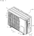
- Fig. 1 is a perspective view of an exemplary appearance of an outdoor unit (hereinafter, referred to as an "outdoor unit 100") of an air-conditioning apparatus according to Embodiment 1 of the invention.
- Fig. 2 is a perspective view of an exemplary internal configuration of the outdoor unit 100. A schematic configuration and operation of the outdoor unit 100 will be described with reference to Figs. 1 and 2 .
- components a compressor 6, a heat exchanger 1, a pressure reducing device, and another heat exchanger mounted in the outdoor unit 100 and an indoor unit (not illustrated) are connected by pipes to achieve a refrigeration cycle operation.
- the outdoor unit 100 includes a top panel 31 defining an upper surface, a front panel 32 defining a front surface, side panels 33 each defining a side surface, and a base plate 12 defining a bottom surface so as to be surrounded by the panels and the plate.
- the base plate 12 is provided with legs 11 for securing the outdoor unit 100 in an installation site.
- the base plate 12 is further provided with a drain water drainage hose connection socket, which will be described in detail later, such that the socket is disposed in back part of the base plate 12 close to the rear surface of the outdoor unit 100.
- the outdoor unit 100 has an interior space partitioned by a separator 10 into an air-sending device chamber 5 and a machine chamber 9.
- the machine chamber 9 accommodates an electric component (control box) 8 or the like in which, for example, the compressor 6, a refrigerant pipe 7, and a controller are mounted.
- the air-sending device chamber 5 accommodates the heat exchanger 1 having a plurality of inlets and outlets, a propeller fan 2, a motor 3 to which the propeller fan 2 is attached, and a motor support 4 that supports the motor 3.
- the components e.g., the compressor 6, the heat exchanger 1, and the motor support 4) arranged in the outdoor unit 100 are held on the base plate 12.
- the compressor 6 is configured to suck a refrigerant, compress the refrigerant into a high-temperature high-pressure state, and discharge the resultant refrigerant through the refrigerant pipe 7 to a refrigerant circuit.
- the electric component 8 is configured to accommodate the components, such as the controller for controlling the operation of the outdoor unit 100, and supply power to the components.
- the heat exchanger 1 is configured to exchange heat between outside air and the refrigerant, function as an evaporator in a heating operation, and function as a condenser in a cooling operation.
- the heat exchanger 1 includes heat transfer pipes through which the refrigerant is allowed to pass and fins for increasing the area of heat transfer between the refrigerant flowing through the heat transfer pipes and the outside air.
- the heat exchanger 1 includes a side flat portion 1a, a corner portion 1b, and a rear flat portion 1c and is accordingly L-shaped. Although the L-shaped heat exchanger 1 is illustrated, the heat exchanger 1 may be of a flat type or a U-shaped type that has bent end portions.
- the propeller fan 2 is rotated and driven by the motor 3 and is configured to send air to the heat exchanger 1.
- the propeller fan 2 operates to allow the air to flow through the side flat portion 1a, the corner portion 1b, and the rear flat portion 1c of the heat exchanger 1 into the outdoor unit 100.
- the air passes through the propeller fan 2 and flows toward the front of the outdoor unit 100.
- the motor 3 is connected through a rotary shaft to the propeller fan 2 and is configured to rotate and drive the propeller fan 2 in accordance with an instruction from the electric component 8. Furthermore, the motor 3 is supported by the motor support 4.
- the motor support 4 includes a pillar that extends vertically (in a direction indicated by arrows Z). An upper end of the motor support 4 is connected to upper part of the heat exchanger 1 and a lower end thereof is fastened to the base plate 12 by a bolt or the like.
- the refrigerant sent from the indoor unit (not illustrated) is sucked into the compressor 6.
- the sucked refrigerant is compressed by the compressor 6 and is then discharged from the compressor 6.
- the refrigerant discharged from the compressor 6 is sent through the refrigerant pipe 7 to the heat exchanger 1.
- the heat exchanger 1 is supplied with air by the propeller fan 2.
- the heat exchanger 1 functions as a condenser in the cooling operation
- the refrigerant which has flowed into the heat exchanger 1 is cooled by the air from the propeller fan 2.
- the air passing through the heat exchanger 1 exchanges heat with the refrigerant flowing through the heat exchanger 1, so that the air is heated.
- the refrigerant cooled in the heat exchanger 1 is discharged from the heat exchanger 1 and is then sent to the pressure reducing device (not illustrated).
- the refrigerant is expanded and pressure-reduced by the pressure reducing device.
- the pressure-reduced refrigerant flows into the heat exchanger in the indoor unit.
- the refrigerant which has flowed into the heat exchanger in the indoor unit cools air supplied through an indoor fan (not illustrated).
- the cooled air is sent to an air-conditioned space, such as a room, thus achieving the cooling operation.
- the refrigerant which has cooled the air flows out of the heat exchanger in the indoor unit and is then again sucked into the compressor 6.
- Fig. 3 is a perspective view of the outdoor unit 100 as seen from below. A configuration of the bottom of the outdoor unit 100 will be described in detail with reference to Fig. 3 .
- the base plate 12 of the outdoor unit 100 has a hole 13. Furthermore, the base plate 12 has a slope downwardly extending to the hole 13. The slope allows drain water generated in the outdoor unit 100 and rain water in the air-sending device chamber 5 to be drained through the hole 13. Since the base plate 12 has the slope downwardly extending to the hole 13, water is prevented from remaining on the base plate 12 for a long time. Thus, water can be prevented from freezing on the base plate 12 and rust can be prevented from being formed on the base plate 12. Furthermore, in the outdoor unit 100, the base plate 12 has the single hole 13 to facilitate concentrated drainage.
- Fig. 4 is a perspective view of a configuration of the drain water drainage hose connection socket (hereinafter, referred to as a "socket 50") of the outdoor unit 100.
- Fig. 5 is an enlarged view of a hose connection portion 51 of the socket 50 of the outdoor unit 100.
- Fig. 6 is a side elevational view of the socket 50 attached to the base plate 12 of the outdoor unit 100.
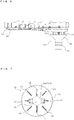
- Fig. 7 is a top plan view of the socket 50 of the outdoor unit 100.
- the socket 50 will be described below with reference to Figs. 4 to 7 .
- a lower end of any part or component in a state in which the socket 50 is attached to the base plate 12 will be referred to as a "first end” and an upper end thereof will be referred to as a "second end.”
- the socket 50 is disposed in the back part of the base plate 12. Specifically, the socket 50 is attached to the hole 13 of the base plate 12, so that the socket 50 is disposed on the base plate 12. Since the base plate 12 has the single hole 13 as described above with reference to Fig. 3 , the number of sockets 50 may also be one. This results in lower cost. Furthermore, drainage arrangement may be performed at a single position in installation of the outdoor unit 100, thus improving the ease of installation.
- the socket 50 includes the hose connection portion 51 to which a drainage hose is connected and a base plate connection portion 52 attached to the base plate 12.
- the socket 50 is made of resin, for example. Furthermore, the socket 50 and the hole 13 constitute a first drainage path.
- the hose connection portion 51 is a hollow cylinder which has an inlet 51a and an outlet 51b and through which water flows.
- the hose connection portion 51 includes a corrugated part 19 and a cylindrical straight part 20 which are connected in series as illustrated in Fig. 5 . While the socket 50 is attached to the base plate 12, the corrugated part 19 is upper part of the socket 50 and the cylindrical straight part 20 is lower part thereof.
- the corrugated part 19 includes a plurality of downwardly tapered sections and is therefore corrugated.
- a rubber tube serving as a drainage hose
- the rubber tube is easily fitted over the corrugated part 19 because a small lower end of each tapered section of the corrugated part 19 facilitates insertion of the rubber tube on the tapered sections.
- the rubber tube is disconnected from the corrugated part 19, it is difficult to detach the rubber tube because a large upper end of each tapered section of the corrugated part 19 acts as a drag.
- the corrugated part 19 may include any number of tapered sections and each section may have any taper angle.
- Hoses used in installation sites include rubber tubes and vinyl chloride pipes.
- the rubber tube may be fitted over the corrugated part 19 as described above.
- the vinyl chloride pipe may be fitted over the cylindrical straight part 20. Accordingly, if an installation worker prepares either of the two types of hose, the hose can be connected to the socket 50. Thus, the ease of installation can be improved.
- the cylindrical straight part 20 may be tapered from the outlet 51b to the inlet 51a. Thus, ease of insertion of a pipe to be connected can be improved.
- Fig. 10 is a side elevational view of another configuration of the socket 50 of the outdoor unit 100.
- Fig. 11 is a side elevational view of still another configuration of the socket 50 of the outdoor unit 100.
- the other configurations of the socket 50 will be described below with reference to Figs. 10 and 11 .
- the terms “upper” or “top” and “lower” or “bottom” are intended to indicate “upper” or “top” and “lower” or “bottom” in a state in which the socket 50 is attached to the outdoor unit 100.
- the hose connection portion 51 illustrated in Fig. 4 includes the corrugated part 19 and the cylindrical straight part 20 connected in series such that the corrugated part 19 is the upper part (on an inlet side) and the cylindrical straight part 20 is the lower part
- the hose connection portion 51 may include a cylindrical straight part 20a having a different outside diameter from the cylindrical straight part 20 instead of the corrugated part 19 as illustrated in Fig. 10 such that the cylindrical straight parts 20a and 20 are connected in series.
- the cylindrical straight part 20a having a larger outside diameter may be disposed on the upper side (the inlet side).
- the hose connection portion 51 with this configuration is connectable to vinyl chloride pipes of two different diameters. Thus, the ease of installation can be further improved.
- each cylindrical straight part may be tapered from the outlet 51a to the inlet 51b, thus improving the ease of insertion of a pipe to be connected.
- the hose connection portion 51 may include the corrugated part 19, the cylindrical straight part 20, and the cylindrical straight part 20a having a different outside diameter from the cylindrical straight part 20 such that the parts are connected in series.
- the corrugated part 19, the cylindrical straight part 20a, and the cylindrical straight part 20 may be connected in that order from the top (the inlet side).
- the base plate connection portion 52 includes an outer wall part 52a, lugs 14, and catches 17.
- the outer wall part 52a is hollow and defines an outer wall of the base plate connection portion 52.
- the outer wall part 52a is an isosceles trapezoid in side view such that the diameter of the outer wall part 52a is reduced toward the hose connection portion 51 (in other words, the diameter thereof is increased toward the base plate 12) as illustrated in Fig. 6 .
- the outer wall part 52a has a first end connected to a second end of the hose connection portion 51, namely, the periphery of the inlet 51a.
- the base plate connection portion 52 and the hose connection portion 51 are in communication to provide the first drainage path through which water flows.
- the outer wall part 52a has a second end that is open.
- the lugs 14 each have a first end connected to an inner surface of the outer wall part 52a and a second end projecting toward the base plate 12.
- the lugs 14 are arranged at regular intervals around the inlet 51a.
- the second ends of the lugs 14 project beyond the second end of the outer wall part 52a.
- the second end of the outer wall part 52a is not in contact with a lower surface of base-plate back part 15 of the base plate 12 but the second ends of the lugs 14 are in contact with the lower surface of the base-plate back part 15 of the base plate 12. Consequently, a clearance 16 can be provided between the lower surface of the base-plate back part 15 of the base plate 12 and the second end of the outer wall part 52a of the socket 50. This clearance 16 functions as a second drainage path.
- each lug 14 is a single-piece flat plate and the lugs 14 are radially arranged in Fig. 4
- the lugs 14 may have any shape and be arranged in any pattern.
- each lug 14 may be V-shaped, cross-shaped, or W-shaped when viewed from above.
- the lugs 14 may be arranged orthogonal to a radial direction of the socket 50. In other words, the lugs 14 may have any shape and be arranged in any pattern unless the clearance 16 can be provided and drain water can be drained through the clearance 16.
- Each of the catches 17 has a first end connected to the inner surface of the outer wall part 52a and a second end projecting toward the base plate 12.
- the catch 17 includes a support 17a and a protrusion 17b and is configured to fasten the socket 50 to the base plate 12 such that when the catch 17 is inserted into the hole 13, the protrusion 17b is engaged with a peripheral edge of the hole 13 inside the outdoor unit 100. Accordingly, the support 17a of the catch 17 is longer than the lug 14.
- the protrusion 17b protrudes outwardly from a free end of the support 17a.
- Fig. 12 is a perspective view of the socket 50 of the outdoor unit 100. Another configuration of the catch 17 will be described with reference to Fig. 12 .
- the support 17a of each catch 17 has an elongated hole 17c as illustrated in Fig. 12 . Accordingly, the catch 17 is easy to deform, thus improving ease of attachment of the socket 50.
- the elongated hole 17c be a slit, the dimensions of the elongated hole 17c may be determined relative to the lugs 14.
- the elongated hole 17c may have any shape and size.
- each catch 17 straddles the lug 14 such that the lug 14 extends through the elongated hole 17c of the catch 17. Accordingly, if water is accumulated at the intersection, the water can be drained through the elongated hole 17c.
- ice does not tend to grow at the intersection.
- the clearance 16 is intentionally provided so as to be greater than or equal to 5 mm by arranging the lugs 14 around the inlet 51a of the socket 50 and bringing the second ends of the lugs 14 into contact with the lower surface of the base-plate back part 15. If drain water freezes in a connected hose or the drain water drainage path in the socket 50 such that ice grows in the backflow direction, the clearance 16 allows drain water to flow out of the outdoor unit 100 before the ice intrudes into the outdoor unit 100. In other words, if the first drainage path is blocked with ice, the clearance 16 can function as the second drainage path such that drain water is continuously drained.
- the likelihood of the outdoor unit 100 being damaged due to frozen drain water can be significantly reduced.
- Fig. 13 is a front view of the outdoor unit 100 in an exemplary installed state.
- the clearance 16 will be described with reference to Fig. 13 .
- the outdoor unit 100 of the air-conditioning apparatus is typically installed such that the legs 11 are fixed to mounts 101 as illustrated in Fig. 13 .
- the socket 50 has to be disposed in a placement space provided between the base plate 12 and a lower surface of each mount 101.
- the clearance 16 greater than or equal to 5 mm is provided as described above. As the clearance 16 is larger, the drainage is more effectively enhanced. Since the socket 50 has to be disposed in the placement space, however, the length or height of the socket 50 is preferably short as much as possible. Increasing the clearance 16 causes the length of the socket 50 to be increased. Considering the placement space for the socket 50 and the length of the hose connection portion 51, it is therefore preferred that the clearance 16 be up to 15 mm.
- the second ends of the lugs 14 are in contact with the lower surface of the base-plate back part 15. Accordingly, at least two catches 17 enable the socket 50 to be stably attached to the base plate 12 with no inclination.
- the at least two catches 17 are preferably arranged so as to be opposed to each other.
- this clearance illustrated in Fig. 4 of Patent Literature 1 is a very small clearance provided for engagement between a socket and a base plate and has a completely different function from the clearance 16 illustrated in Fig. 6 .
- the clearance 16 is provided not for engagement between the socket 50 and the base plate 12 but for drainage of drain water, flowing from the inside of the outdoor unit 100, out of the outdoor unit 100 without using the drainage hose while the drain water drainage path (first drainage path) is blocked with frozen drain water.
- the socket 50 includes a rib 18 as illustrated in Fig. 7 .
- the rib 18 may be disposed in the drain water drainage path (first drainage path) and may be provided for at least one of the hose connection portion 51 and the base plate connection portion 52.
- the rib 18 is provided so as to extend across a cross-section of the drain water drainage path.
- a bird or another small animal can intrude into a typical related-art outdoor unit through a hole in a base plate of the outdoor unit and build a nest inside the outdoor unit, thus damaging the outdoor unit. This is a common occurrence.
- a drain water drainage hose connection socket can be attached to the base plate in order to close the hole, thereby considerably preventing the intrusion of a bird or another small animal into the outdoor unit.
- cold climate areas however, the use of the drain water drainage hose connection socket has been prohibited.
- the socket 50 includes the rib 18 disposed in the drain water drainage path such that the rib 18 extends across a cross-section of the drainage path, thus partly closing the hole 13 of the base plate 12. This eliminates an intrusion space for birds and small animals and therefore considerably prevents birds and small animals from building a nest in the outdoor unit 100.
- the rib 18 may have any shape and size and any number of ribs 18 may be arranged. The shape and size of the rib 18 and the number of ribs 18 may be determined on the basis of the diameter of the hole 13 and the sizes of birds and small animals likely to intrude. Furthermore, the rib 18 may be separate from the socket 50 and be attachable to the socket 50.
- the rib 18 may be made of any material.
- the outdoor unit 100 since the outdoor unit 100 includes the socket 50 capable of providing the clearance 16 when attached to the base plate 12, the outdoor unit 100 can be used in cold climate areas.
- the hose connection portion 51 of the socket 50 is configured such that any of a rubber tube and a vinyl chloride pipe can be fitted on the hose connection portion 51, the ease of installation can be improved.
- Fig. 8 is a rear view of an outdoor unit (hereinafter, referred to as an "outdoor unit 100A") of an air-conditioning apparatus according to Embodiment 2 of the invention, lower part of the outdoor unit 100A being illustrated in enlarged view.
- a configuration of the outdoor unit 100A will be described with reference to Fig. 8 .
- components a compressor 6, a heat exchanger 1, a pressure reducing device, and another heat exchanger mounted in the outdoor unit 100A and an indoor unit (not illustrated) are connected by pipes to achieve a refrigeration cycle operation.
- the difference from Embodiment 1 described above will be mainly described.
- the same functional components as those in Embodiment 1 are designated by the same reference numerals and description thereof is omitted.
- the base plate 12 has the single hole 13 and the single socket 50 is disposed.
- a base plate 12 has a plurality of holes 13 and multiple sockets 50 are arranged as illustrated in Fig. 8 . If any one of the holes 13 is completely blocked with frozen drain water, therefore, drainage can be achieved through the other holes 13, thus leading to more certainty of preventing freezing.
- multiple sockets 50 if the base plate 12 has slopes each downwardly extending to the hole 13, water does not remain on the base plate 12 for a long time, thus preventing water from freezing.
- the outdoor unit 100A is provided with the sockets 50 capable of providing a clearance 16 when attached to the base plate 12, as described above. Accordingly, the outdoor unit 100A can be used in cold climate areas. Furthermore, since each socket 50 includes a hose connection portion 51 configured such that any of a rubber tube and a vinyl chloride pipe can be fitted on the hose connection portion 51, the ease of installation can be improved. In addition, since the multiple holes 13 are arranged, the certainty of preventing freezing is increased.
- Fig. 9 is a perspective view of a base plate of an outdoor unit (hereinafter, referred to as an "outdoor unit 100B") of an air-conditioning apparatus according to Embodiment 3 of the invention when viewed from above.
- An outdoor unit 100B A configuration of the outdoor unit 100B will be described with reference to Fig. 9 .
- components a compressor 6, a heat exchanger 1, a pressure reducing device, and another heat exchanger mounted in the outdoor unit 100B and an indoor unit (not illustrated) are connected by pipes to achieve a refrigeration cycle operation.
- the difference from Embodiment 1 described above will be mainly described.
- the same functional components as those in Embodiment 1 are designated by the same reference numerals and description thereof is omitted.
- a heater 21 is disposed on a base plate 12. Consequently, heat generated by the heater 21 is transferred to the base plate 12, thereby preventing drain water from freezing. Accordingly, the outdoor unit 100B achieves drainage through a hole 13 of the base plate 12, a socket 50, and a drainage hose in that order with high certainty.
- the outdoor unit 100B includes the socket 50 capable of providing a clearance 16 when attached to the base plate 12, as described above. Accordingly, the outdoor unit 100B can be used in cold climate areas. Additionally, since the socket 50 includes a hose connection portion 51 configured such that any of a rubber tube and a vinyl chloride pipe can be fitted on the hose connection portion 51, the ease of installation can be improved. Furthermore, since the heater 21 is provided, the certainty of normal drainage is increased. Note that the heater 21 may be disposed in Embodiment 2.
Landscapes
- Engineering & Computer Science (AREA)
- Chemical & Material Sciences (AREA)
- Combustion & Propulsion (AREA)
- Mechanical Engineering (AREA)
- General Engineering & Computer Science (AREA)
- Physics & Mathematics (AREA)
- Thermal Sciences (AREA)
- Other Air-Conditioning Systems (AREA)
- Devices For Blowing Cold Air, Devices For Blowing Warm Air, And Means For Preventing Water Condensation In Air Conditioning Units (AREA)
Applications Claiming Priority (2)
| Application Number | Priority Date | Filing Date | Title |
|---|---|---|---|
| JP2013007261 | 2013-01-18 | ||
| JP2013144549A JP6404546B2 (ja) | 2013-01-18 | 2013-07-10 | 空気調和機の室外機 |
Publications (2)
| Publication Number | Publication Date |
|---|---|
| EP2757329A1 EP2757329A1 (en) | 2014-07-23 |
| EP2757329B1 true EP2757329B1 (en) | 2019-06-05 |
Family
ID=49546297
Family Applications (1)
| Application Number | Title | Priority Date | Filing Date |
|---|---|---|---|
| EP13191682.7A Not-in-force EP2757329B1 (en) | 2013-01-18 | 2013-11-05 | Outdoor unit of air-conditioning apparatus |
Country Status (4)
| Country | Link |
|---|---|
| US (1) | US20140202191A1 (enExample) |
| EP (1) | EP2757329B1 (enExample) |
| JP (1) | JP6404546B2 (enExample) |
| CN (2) | CN203642380U (enExample) |
Families Citing this family (13)
| Publication number | Priority date | Publication date | Assignee | Title |
|---|---|---|---|---|
| JP5831431B2 (ja) * | 2012-11-15 | 2015-12-09 | 三菱電機株式会社 | 空気調和機の室外機 |
| US10208968B2 (en) * | 2014-12-26 | 2019-02-19 | Mitsubishi Electric Corporation | Outdoor unit |
| EP3059507B1 (en) * | 2014-12-26 | 2018-03-14 | Mitsubishi Electric Corporation | Outdoor unit |
| US20160209055A1 (en) | 2015-01-20 | 2016-07-21 | Allied Air Enterprises Llc | Systems and methods for a heating and cooling unit and components thereof |
| JP6361685B2 (ja) * | 2016-04-21 | 2018-07-25 | ダイキン工業株式会社 | 熱源ユニット |
| WO2018011939A1 (ja) | 2016-07-14 | 2018-01-18 | 三菱電機株式会社 | 空気調和機の室外機 |
| DE102016010630A1 (de) | 2016-09-05 | 2018-03-08 | Stiebel Eltron Gmbh & Co. Kg | Luft- Wasserwärmepumpe mit einem Gehäuse für eine Außenaufstellung |
| CN108826518A (zh) * | 2018-05-11 | 2018-11-16 | 广西富荔科技有限公司 | 一种便于散热的变频空调主机盒 |
| KR102556967B1 (ko) | 2018-08-23 | 2023-07-18 | 엘지전자 주식회사 | 제습기 |
| KR102069074B1 (ko) * | 2018-08-23 | 2020-01-22 | 엘지전자 주식회사 | 제습기 |
| CN109631475B (zh) * | 2018-12-12 | 2021-03-26 | 广州美的华凌冰箱有限公司 | 外置排水管及冰箱 |
| US11293688B2 (en) * | 2020-09-02 | 2022-04-05 | Whirlpool Corporation | Drainage assembly |
| EP4462032A4 (en) * | 2022-07-15 | 2025-06-11 | Samsung Electronics Co., Ltd. | AIR CONDITIONER OUTDOOR UNIT |
Family Cites Families (14)
| Publication number | Priority date | Publication date | Assignee | Title |
|---|---|---|---|---|
| JPS6146366U (ja) * | 1984-08-29 | 1986-03-27 | 株式会社東芝 | 空気調和機の室外ユニツト |
| US4793147A (en) * | 1986-09-16 | 1988-12-27 | Sam Sung Electronic Co., Ltd. | Drainage device for room air conditioner |
| JPH0612426Y2 (ja) * | 1987-10-30 | 1994-03-30 | 三菱電機株式会社 | 空気調和機 |
| JPH0493466U (enExample) * | 1990-12-28 | 1992-08-13 | ||
| JPH04302980A (ja) * | 1991-03-29 | 1992-10-26 | Hitachi Ltd | 冷蔵庫 |
| JP3882910B2 (ja) * | 2002-08-08 | 2007-02-21 | 三菱電機株式会社 | 空気調和機の室外機 |
| JP3996814B2 (ja) * | 2002-08-09 | 2007-10-24 | 株式会社三栄水栓製作所 | 排水用簡易接続部材 |
| JP2006082725A (ja) * | 2004-09-16 | 2006-03-30 | Denso Corp | 空調装置 |
| JP4761894B2 (ja) * | 2005-08-29 | 2011-08-31 | 三菱電機株式会社 | ヒートポンプ式給湯機用熱交換ユニットのドレン排水装置 |
| JP4892713B2 (ja) * | 2008-08-25 | 2012-03-07 | シャープ株式会社 | 空気調和機 |
| JP5014304B2 (ja) * | 2008-10-22 | 2012-08-29 | 三菱電機株式会社 | 空気調和機のドレンソケット及びこれを備えた空気調和機の室外ユニット |
| CN102022814A (zh) * | 2009-09-22 | 2011-04-20 | 乐金电子(天津)电器有限公司 | 一体式窗式空调 |
| JP3161616U (ja) * | 2010-05-24 | 2010-08-05 | 株式会社日本アムス | 排水用受け筒 |
| CN201779832U (zh) * | 2010-09-02 | 2011-03-30 | 海尔集团公司 | 空调室外机用防冻结底盘及空调装置 |
-
2013
- 2013-07-10 JP JP2013144549A patent/JP6404546B2/ja active Active
- 2013-10-23 US US14/060,895 patent/US20140202191A1/en not_active Abandoned
- 2013-11-05 EP EP13191682.7A patent/EP2757329B1/en not_active Not-in-force
- 2013-11-29 CN CN201320774107.2U patent/CN203642380U/zh not_active Expired - Lifetime
- 2013-11-29 CN CN201310628171.4A patent/CN103940005B/zh not_active Expired - Fee Related
Non-Patent Citations (1)
| Title |
|---|
| None * |
Also Published As
| Publication number | Publication date |
|---|---|
| JP2014157008A (ja) | 2014-08-28 |
| CN103940005B (zh) | 2016-08-17 |
| JP6404546B2 (ja) | 2018-10-10 |
| CN103940005A (zh) | 2014-07-23 |
| CN203642380U (zh) | 2014-06-11 |
| EP2757329A1 (en) | 2014-07-23 |
| US20140202191A1 (en) | 2014-07-24 |
Similar Documents
| Publication | Publication Date | Title |
|---|---|---|
| EP2757329B1 (en) | Outdoor unit of air-conditioning apparatus | |
| EP2815187B1 (en) | Air-conditioning apparatus | |
| US11761643B2 (en) | Condensate collecting base member for a heating and cooling unit | |
| US5461879A (en) | Air conditioner condensate slinger | |
| US20140165640A1 (en) | Outdoor unit of air-conditioning apparatus | |
| CN106196332B (zh) | 空调机的室外机 | |
| US20210404673A1 (en) | External-air conditioning apparatus and ventilation system | |
| JP6710279B2 (ja) | ドレンパンおよび冷凍サイクル装置 | |
| KR20170000177A (ko) | 드레인호스 및 이를 포함하는 공기조화기 | |
| US20150338124A1 (en) | Wind direction adjusting device of air-conditioning apparatus and air-conditioning apparatus | |
| CN112888903B (zh) | 空调室内机的组装结构 | |
| US5468186A (en) | Snap-on air deflectors for air conditioner | |
| KR102466274B1 (ko) | 공기조화기 | |
| US5454231A (en) | Room air conditioner front inlet grille mounting | |
| WO2017002237A1 (ja) | 室内機および空気調和装置 | |
| CN111148947B (zh) | 空调装置的室内机以及空调装置 | |
| EP3722682B1 (en) | Indoor unit of air conditioning apparatus, and air conditioning apparatus | |
| CN205980073U (zh) | 空调器室外机的接水盘及空调器室外机 | |
| KR101224645B1 (ko) | 공기조화기용 실내기의 팽창밸브 설치장치 | |
| JPH094871A (ja) | 天井埋込型空気調和機 | |
| CN222068846U (zh) | 空调器 | |
| CN223610241U (zh) | 空调室外机 | |
| US20230126562A1 (en) | Installation plate for indoor unit | |
| JPH0410497Y2 (enExample) | ||
| KR20240083640A (ko) | 매립형 에어컨 실내기의 설치 구조 및 이를 적용한 천장형 에어컨 실내기 |
Legal Events
| Date | Code | Title | Description |
|---|---|---|---|
| PUAI | Public reference made under article 153(3) epc to a published international application that has entered the european phase |
Free format text: ORIGINAL CODE: 0009012 |
|
| 17P | Request for examination filed |
Effective date: 20131105 |
|
| AK | Designated contracting states |
Kind code of ref document: A1 Designated state(s): AL AT BE BG CH CY CZ DE DK EE ES FI FR GB GR HR HU IE IS IT LI LT LU LV MC MK MT NL NO PL PT RO RS SE SI SK SM TR |
|
| AX | Request for extension of the european patent |
Extension state: BA ME |
|
| R17P | Request for examination filed (corrected) |
Effective date: 20150116 |
|
| RBV | Designated contracting states (corrected) |
Designated state(s): AL AT BE BG CH CY CZ DE DK EE ES FI FR GB GR HR HU IE IS IT LI LT LU LV MC MK MT NL NO PL PT RO RS SE SI SK SM TR |
|
| STAA | Information on the status of an ep patent application or granted ep patent |
Free format text: STATUS: EXAMINATION IS IN PROGRESS |
|
| 17Q | First examination report despatched |
Effective date: 20180712 |
|
| GRAP | Despatch of communication of intention to grant a patent |
Free format text: ORIGINAL CODE: EPIDOSNIGR1 |
|
| STAA | Information on the status of an ep patent application or granted ep patent |
Free format text: STATUS: GRANT OF PATENT IS INTENDED |
|
| INTG | Intention to grant announced |
Effective date: 20190103 |
|
| GRAS | Grant fee paid |
Free format text: ORIGINAL CODE: EPIDOSNIGR3 |
|
| GRAA | (expected) grant |
Free format text: ORIGINAL CODE: 0009210 |
|
| STAA | Information on the status of an ep patent application or granted ep patent |
Free format text: STATUS: THE PATENT HAS BEEN GRANTED |
|
| AK | Designated contracting states |
Kind code of ref document: B1 Designated state(s): AL AT BE BG CH CY CZ DE DK EE ES FI FR GB GR HR HU IE IS IT LI LT LU LV MC MK MT NL NO PL PT RO RS SE SI SK SM TR |
|
| REG | Reference to a national code |
Ref country code: GB Ref legal event code: FG4D |
|
| REG | Reference to a national code |
Ref country code: CH Ref legal event code: EP |
|
| REG | Reference to a national code |
Ref country code: AT Ref legal event code: REF Ref document number: 1140411 Country of ref document: AT Kind code of ref document: T Effective date: 20190615 |
|
| REG | Reference to a national code |
Ref country code: IE Ref legal event code: FG4D |
|
| REG | Reference to a national code |
Ref country code: DE Ref legal event code: R096 Ref document number: 602013056145 Country of ref document: DE |
|
| REG | Reference to a national code |
Ref country code: SE Ref legal event code: TRGR |
|
| REG | Reference to a national code |
Ref country code: NL Ref legal event code: MP Effective date: 20190605 |
|
| REG | Reference to a national code |
Ref country code: LT Ref legal event code: MG4D |
|
| PG25 | Lapsed in a contracting state [announced via postgrant information from national office to epo] |
Ref country code: AL Free format text: LAPSE BECAUSE OF FAILURE TO SUBMIT A TRANSLATION OF THE DESCRIPTION OR TO PAY THE FEE WITHIN THE PRESCRIBED TIME-LIMIT Effective date: 20190605 Ref country code: ES Free format text: LAPSE BECAUSE OF FAILURE TO SUBMIT A TRANSLATION OF THE DESCRIPTION OR TO PAY THE FEE WITHIN THE PRESCRIBED TIME-LIMIT Effective date: 20190605 Ref country code: NO Free format text: LAPSE BECAUSE OF FAILURE TO SUBMIT A TRANSLATION OF THE DESCRIPTION OR TO PAY THE FEE WITHIN THE PRESCRIBED TIME-LIMIT Effective date: 20190905 Ref country code: HR Free format text: LAPSE BECAUSE OF FAILURE TO SUBMIT A TRANSLATION OF THE DESCRIPTION OR TO PAY THE FEE WITHIN THE PRESCRIBED TIME-LIMIT Effective date: 20190605 Ref country code: LT Free format text: LAPSE BECAUSE OF FAILURE TO SUBMIT A TRANSLATION OF THE DESCRIPTION OR TO PAY THE FEE WITHIN THE PRESCRIBED TIME-LIMIT Effective date: 20190605 Ref country code: FI Free format text: LAPSE BECAUSE OF FAILURE TO SUBMIT A TRANSLATION OF THE DESCRIPTION OR TO PAY THE FEE WITHIN THE PRESCRIBED TIME-LIMIT Effective date: 20190605 |
|
| PG25 | Lapsed in a contracting state [announced via postgrant information from national office to epo] |
Ref country code: LV Free format text: LAPSE BECAUSE OF FAILURE TO SUBMIT A TRANSLATION OF THE DESCRIPTION OR TO PAY THE FEE WITHIN THE PRESCRIBED TIME-LIMIT Effective date: 20190605 Ref country code: RS Free format text: LAPSE BECAUSE OF FAILURE TO SUBMIT A TRANSLATION OF THE DESCRIPTION OR TO PAY THE FEE WITHIN THE PRESCRIBED TIME-LIMIT Effective date: 20190605 Ref country code: BG Free format text: LAPSE BECAUSE OF FAILURE TO SUBMIT A TRANSLATION OF THE DESCRIPTION OR TO PAY THE FEE WITHIN THE PRESCRIBED TIME-LIMIT Effective date: 20190905 Ref country code: GR Free format text: LAPSE BECAUSE OF FAILURE TO SUBMIT A TRANSLATION OF THE DESCRIPTION OR TO PAY THE FEE WITHIN THE PRESCRIBED TIME-LIMIT Effective date: 20190906 |
|
| REG | Reference to a national code |
Ref country code: AT Ref legal event code: MK05 Ref document number: 1140411 Country of ref document: AT Kind code of ref document: T Effective date: 20190605 |
|
| PG25 | Lapsed in a contracting state [announced via postgrant information from national office to epo] |
Ref country code: PT Free format text: LAPSE BECAUSE OF FAILURE TO SUBMIT A TRANSLATION OF THE DESCRIPTION OR TO PAY THE FEE WITHIN THE PRESCRIBED TIME-LIMIT Effective date: 20191007 Ref country code: SK Free format text: LAPSE BECAUSE OF FAILURE TO SUBMIT A TRANSLATION OF THE DESCRIPTION OR TO PAY THE FEE WITHIN THE PRESCRIBED TIME-LIMIT Effective date: 20190605 Ref country code: EE Free format text: LAPSE BECAUSE OF FAILURE TO SUBMIT A TRANSLATION OF THE DESCRIPTION OR TO PAY THE FEE WITHIN THE PRESCRIBED TIME-LIMIT Effective date: 20190605 Ref country code: AT Free format text: LAPSE BECAUSE OF FAILURE TO SUBMIT A TRANSLATION OF THE DESCRIPTION OR TO PAY THE FEE WITHIN THE PRESCRIBED TIME-LIMIT Effective date: 20190605 Ref country code: CZ Free format text: LAPSE BECAUSE OF FAILURE TO SUBMIT A TRANSLATION OF THE DESCRIPTION OR TO PAY THE FEE WITHIN THE PRESCRIBED TIME-LIMIT Effective date: 20190605 Ref country code: NL Free format text: LAPSE BECAUSE OF FAILURE TO SUBMIT A TRANSLATION OF THE DESCRIPTION OR TO PAY THE FEE WITHIN THE PRESCRIBED TIME-LIMIT Effective date: 20190605 Ref country code: RO Free format text: LAPSE BECAUSE OF FAILURE TO SUBMIT A TRANSLATION OF THE DESCRIPTION OR TO PAY THE FEE WITHIN THE PRESCRIBED TIME-LIMIT Effective date: 20190605 |
|
| PGFP | Annual fee paid to national office [announced via postgrant information from national office to epo] |
Ref country code: SE Payment date: 20191111 Year of fee payment: 7 |
|
| PG25 | Lapsed in a contracting state [announced via postgrant information from national office to epo] |
Ref country code: IS Free format text: LAPSE BECAUSE OF FAILURE TO SUBMIT A TRANSLATION OF THE DESCRIPTION OR TO PAY THE FEE WITHIN THE PRESCRIBED TIME-LIMIT Effective date: 20191005 Ref country code: IT Free format text: LAPSE BECAUSE OF FAILURE TO SUBMIT A TRANSLATION OF THE DESCRIPTION OR TO PAY THE FEE WITHIN THE PRESCRIBED TIME-LIMIT Effective date: 20190605 Ref country code: SM Free format text: LAPSE BECAUSE OF FAILURE TO SUBMIT A TRANSLATION OF THE DESCRIPTION OR TO PAY THE FEE WITHIN THE PRESCRIBED TIME-LIMIT Effective date: 20190605 |
|
| REG | Reference to a national code |
Ref country code: DE Ref legal event code: R097 Ref document number: 602013056145 Country of ref document: DE |
|
| PG25 | Lapsed in a contracting state [announced via postgrant information from national office to epo] |
Ref country code: TR Free format text: LAPSE BECAUSE OF FAILURE TO SUBMIT A TRANSLATION OF THE DESCRIPTION OR TO PAY THE FEE WITHIN THE PRESCRIBED TIME-LIMIT Effective date: 20190605 |
|
| PLBE | No opposition filed within time limit |
Free format text: ORIGINAL CODE: 0009261 |
|
| STAA | Information on the status of an ep patent application or granted ep patent |
Free format text: STATUS: NO OPPOSITION FILED WITHIN TIME LIMIT |
|
| PG25 | Lapsed in a contracting state [announced via postgrant information from national office to epo] |
Ref country code: PL Free format text: LAPSE BECAUSE OF FAILURE TO SUBMIT A TRANSLATION OF THE DESCRIPTION OR TO PAY THE FEE WITHIN THE PRESCRIBED TIME-LIMIT Effective date: 20190605 Ref country code: DK Free format text: LAPSE BECAUSE OF FAILURE TO SUBMIT A TRANSLATION OF THE DESCRIPTION OR TO PAY THE FEE WITHIN THE PRESCRIBED TIME-LIMIT Effective date: 20190605 |
|
| 26N | No opposition filed |
Effective date: 20200306 |
|
| PG25 | Lapsed in a contracting state [announced via postgrant information from national office to epo] |
Ref country code: SI Free format text: LAPSE BECAUSE OF FAILURE TO SUBMIT A TRANSLATION OF THE DESCRIPTION OR TO PAY THE FEE WITHIN THE PRESCRIBED TIME-LIMIT Effective date: 20190605 |
|
| REG | Reference to a national code |
Ref country code: CH Ref legal event code: PL |
|
| PG25 | Lapsed in a contracting state [announced via postgrant information from national office to epo] |
Ref country code: CH Free format text: LAPSE BECAUSE OF NON-PAYMENT OF DUE FEES Effective date: 20191130 Ref country code: LI Free format text: LAPSE BECAUSE OF NON-PAYMENT OF DUE FEES Effective date: 20191130 Ref country code: MC Free format text: LAPSE BECAUSE OF FAILURE TO SUBMIT A TRANSLATION OF THE DESCRIPTION OR TO PAY THE FEE WITHIN THE PRESCRIBED TIME-LIMIT Effective date: 20190605 Ref country code: LU Free format text: LAPSE BECAUSE OF NON-PAYMENT OF DUE FEES Effective date: 20191105 |
|
| REG | Reference to a national code |
Ref country code: BE Ref legal event code: MM Effective date: 20191130 |
|
| GBPC | Gb: european patent ceased through non-payment of renewal fee |
Effective date: 20191105 |
|
| PG25 | Lapsed in a contracting state [announced via postgrant information from national office to epo] |
Ref country code: FR Free format text: LAPSE BECAUSE OF NON-PAYMENT OF DUE FEES Effective date: 20191130 Ref country code: IE Free format text: LAPSE BECAUSE OF NON-PAYMENT OF DUE FEES Effective date: 20191105 Ref country code: GB Free format text: LAPSE BECAUSE OF NON-PAYMENT OF DUE FEES Effective date: 20191105 |
|
| PG25 | Lapsed in a contracting state [announced via postgrant information from national office to epo] |
Ref country code: BE Free format text: LAPSE BECAUSE OF NON-PAYMENT OF DUE FEES Effective date: 20191130 |
|
| PGFP | Annual fee paid to national office [announced via postgrant information from national office to epo] |
Ref country code: DE Payment date: 20201020 Year of fee payment: 8 |
|
| PG25 | Lapsed in a contracting state [announced via postgrant information from national office to epo] |
Ref country code: CY Free format text: LAPSE BECAUSE OF FAILURE TO SUBMIT A TRANSLATION OF THE DESCRIPTION OR TO PAY THE FEE WITHIN THE PRESCRIBED TIME-LIMIT Effective date: 20190605 |
|
| REG | Reference to a national code |
Ref country code: SE Ref legal event code: EUG |
|
| PG25 | Lapsed in a contracting state [announced via postgrant information from national office to epo] |
Ref country code: HU Free format text: LAPSE BECAUSE OF FAILURE TO SUBMIT A TRANSLATION OF THE DESCRIPTION OR TO PAY THE FEE WITHIN THE PRESCRIBED TIME-LIMIT; INVALID AB INITIO Effective date: 20131105 Ref country code: MT Free format text: LAPSE BECAUSE OF FAILURE TO SUBMIT A TRANSLATION OF THE DESCRIPTION OR TO PAY THE FEE WITHIN THE PRESCRIBED TIME-LIMIT Effective date: 20190605 |
|
| PG25 | Lapsed in a contracting state [announced via postgrant information from national office to epo] |
Ref country code: SE Free format text: LAPSE BECAUSE OF NON-PAYMENT OF DUE FEES Effective date: 20201106 |
|
| REG | Reference to a national code |
Ref country code: DE Ref legal event code: R119 Ref document number: 602013056145 Country of ref document: DE |
|
| PG25 | Lapsed in a contracting state [announced via postgrant information from national office to epo] |
Ref country code: MK Free format text: LAPSE BECAUSE OF FAILURE TO SUBMIT A TRANSLATION OF THE DESCRIPTION OR TO PAY THE FEE WITHIN THE PRESCRIBED TIME-LIMIT Effective date: 20190605 |
|
| PG25 | Lapsed in a contracting state [announced via postgrant information from national office to epo] |
Ref country code: DE Free format text: LAPSE BECAUSE OF NON-PAYMENT OF DUE FEES Effective date: 20220601 |