EP2756342B1 - Source laser contrôlable à fibre multi-longueur d'onde - Google Patents
Source laser contrôlable à fibre multi-longueur d'onde Download PDFInfo
- Publication number
- EP2756342B1 EP2756342B1 EP12831411.9A EP12831411A EP2756342B1 EP 2756342 B1 EP2756342 B1 EP 2756342B1 EP 12831411 A EP12831411 A EP 12831411A EP 2756342 B1 EP2756342 B1 EP 2756342B1
- Authority
- EP
- European Patent Office
- Prior art keywords
- wavelength
- laser
- polarization
- laser system
- phase
- Prior art date
- Legal status (The legal status is an assumption and is not a legal conclusion. Google has not performed a legal analysis and makes no representation as to the accuracy of the status listed.)
- Not-in-force
Links
Images


Classifications
-
- H—ELECTRICITY
- H01—ELECTRIC ELEMENTS
- H01S—DEVICES USING THE PROCESS OF LIGHT AMPLIFICATION BY STIMULATED EMISSION OF RADIATION [LASER] TO AMPLIFY OR GENERATE LIGHT; DEVICES USING STIMULATED EMISSION OF ELECTROMAGNETIC RADIATION IN WAVE RANGES OTHER THAN OPTICAL
- H01S3/00—Lasers, i.e. devices using stimulated emission of electromagnetic radiation in the infrared, visible or ultraviolet wave range
- H01S3/05—Construction or shape of optical resonators; Accommodation of active medium therein; Shape of active medium
- H01S3/06—Construction or shape of active medium
- H01S3/063—Waveguide lasers, i.e. whereby the dimensions of the waveguide are of the order of the light wavelength
- H01S3/067—Fibre lasers
- H01S3/06708—Constructional details of the fibre, e.g. compositions, cross-section, shape or tapering
- H01S3/06712—Polarising fibre; Polariser
-
- G—PHYSICS
- G02—OPTICS
- G02B—OPTICAL ELEMENTS, SYSTEMS OR APPARATUS
- G02B5/00—Optical elements other than lenses
- G02B5/30—Polarising elements
- G02B5/3083—Birefringent or phase retarding elements
-
- G—PHYSICS
- G02—OPTICS
- G02F—OPTICAL DEVICES OR ARRANGEMENTS FOR THE CONTROL OF LIGHT BY MODIFICATION OF THE OPTICAL PROPERTIES OF THE MEDIA OF THE ELEMENTS INVOLVED THEREIN; NON-LINEAR OPTICS; FREQUENCY-CHANGING OF LIGHT; OPTICAL LOGIC ELEMENTS; OPTICAL ANALOGUE/DIGITAL CONVERTERS
- G02F1/00—Devices or arrangements for the control of the intensity, colour, phase, polarisation or direction of light arriving from an independent light source, e.g. switching, gating or modulating; Non-linear optics
- G02F1/35—Non-linear optics
- G02F1/353—Frequency conversion, i.e. wherein a light beam is generated with frequency components different from those of the incident light beams
- G02F1/3544—Particular phase matching techniques
-
- H—ELECTRICITY
- H01—ELECTRIC ELEMENTS
- H01S—DEVICES USING THE PROCESS OF LIGHT AMPLIFICATION BY STIMULATED EMISSION OF RADIATION [LASER] TO AMPLIFY OR GENERATE LIGHT; DEVICES USING STIMULATED EMISSION OF ELECTROMAGNETIC RADIATION IN WAVE RANGES OTHER THAN OPTICAL
- H01S3/00—Lasers, i.e. devices using stimulated emission of electromagnetic radiation in the infrared, visible or ultraviolet wave range
- H01S3/005—Optical devices external to the laser cavity, specially adapted for lasers, e.g. for homogenisation of the beam or for manipulating laser pulses, e.g. pulse shaping
- H01S3/0092—Nonlinear frequency conversion, e.g. second harmonic generation [SHG] or sum- or difference-frequency generation outside the laser cavity
-
- H—ELECTRICITY
- H01—ELECTRIC ELEMENTS
- H01S—DEVICES USING THE PROCESS OF LIGHT AMPLIFICATION BY STIMULATED EMISSION OF RADIATION [LASER] TO AMPLIFY OR GENERATE LIGHT; DEVICES USING STIMULATED EMISSION OF ELECTROMAGNETIC RADIATION IN WAVE RANGES OTHER THAN OPTICAL
- H01S3/00—Lasers, i.e. devices using stimulated emission of electromagnetic radiation in the infrared, visible or ultraviolet wave range
- H01S3/05—Construction or shape of optical resonators; Accommodation of active medium therein; Shape of active medium
- H01S3/06—Construction or shape of active medium
- H01S3/063—Waveguide lasers, i.e. whereby the dimensions of the waveguide are of the order of the light wavelength
- H01S3/067—Fibre lasers
- H01S3/06754—Fibre amplifiers
-
- H—ELECTRICITY
- H01—ELECTRIC ELEMENTS
- H01S—DEVICES USING THE PROCESS OF LIGHT AMPLIFICATION BY STIMULATED EMISSION OF RADIATION [LASER] TO AMPLIFY OR GENERATE LIGHT; DEVICES USING STIMULATED EMISSION OF ELECTROMAGNETIC RADIATION IN WAVE RANGES OTHER THAN OPTICAL
- H01S3/00—Lasers, i.e. devices using stimulated emission of electromagnetic radiation in the infrared, visible or ultraviolet wave range
- H01S3/10—Controlling the intensity, frequency, phase, polarisation or direction of the emitted radiation, e.g. switching, gating, modulating or demodulating
- H01S3/10053—Phase control
-
- H—ELECTRICITY
- H01—ELECTRIC ELEMENTS
- H01S—DEVICES USING THE PROCESS OF LIGHT AMPLIFICATION BY STIMULATED EMISSION OF RADIATION [LASER] TO AMPLIFY OR GENERATE LIGHT; DEVICES USING STIMULATED EMISSION OF ELECTROMAGNETIC RADIATION IN WAVE RANGES OTHER THAN OPTICAL
- H01S3/00—Lasers, i.e. devices using stimulated emission of electromagnetic radiation in the infrared, visible or ultraviolet wave range
- H01S3/10—Controlling the intensity, frequency, phase, polarisation or direction of the emitted radiation, e.g. switching, gating, modulating or demodulating
- H01S3/10061—Polarization control
-
- G—PHYSICS
- G02—OPTICS
- G02F—OPTICAL DEVICES OR ARRANGEMENTS FOR THE CONTROL OF LIGHT BY MODIFICATION OF THE OPTICAL PROPERTIES OF THE MEDIA OF THE ELEMENTS INVOLVED THEREIN; NON-LINEAR OPTICS; FREQUENCY-CHANGING OF LIGHT; OPTICAL LOGIC ELEMENTS; OPTICAL ANALOGUE/DIGITAL CONVERTERS
- G02F1/00—Devices or arrangements for the control of the intensity, colour, phase, polarisation or direction of light arriving from an independent light source, e.g. switching, gating or modulating; Non-linear optics
- G02F1/35—Non-linear optics
- G02F1/353—Frequency conversion, i.e. wherein a light beam is generated with frequency components different from those of the incident light beams
- G02F1/3544—Particular phase matching techniques
- G02F1/3546—Active phase matching, e.g. by electro- or thermo-optic tuning
Definitions
- the invention relates to a fiber laser source with multiple output wavelengths and, more particularly, to methods and systems for controlling the energy at each wavelength.
- Fiber-based laser systems are now well established for numerous applications, and are particularly well suited for high repetition rate applications at low to medium pulse power.
- Nonlinear optical processes and media may be used to convert a fundamental output wavelength of a fiber laser to another wavelength where a fiber laser source is not available.
- a wavelength converted signal may be generated by harmonic conversion, sum or difference frequency mixing, parametric amplification, Raman shifting, self-phase modulation (SPM) and/or other suitable non-linear processes.
- Utilizing multiple wavelengths can be beneficial. For example, in terahertz applications, one wavelength is used to generate THz radiation and the other wavelength is used to detect THz pulses. Similarly, in time gating pump and probe measurements the first wavelength is used to excite the object and the second wavelength is used as probe. In some laser processing applications, the first wavelength can be used to pre-process a target material and the second wavelength used to further process the target.
- U.S. Patent 5,450,427 US 5,818,630 ; US, 5,880,877 .
- U.S. Patent 5,361,268 discloses a switchable two-wavelength frequency converting laser system.
- switching laser output between the pump wavelength and the signal wavelength can be done by shifting a nonlinear crystal in and out of the pump laser beam, or by steering the pump laser beam on and off the crystal.
- this provides either the pump or signal as a single output, without continuous or high resolution control of either pump or signal power.
- tuning the phase matching of the nonlinear crystal by changing temperature, incident angle, etc. can change the power of the signal light.
- the adjusting range is usually limited and the tuning may affect the wavelength.
- multiple optical paths can be utilized with optical modulators/deflectors to selectively direct pump radiation to the non-linear crystal or to the output, but such an arrangement can increase system complexity.
- the phase matching condition in the nonlinear crystal is usually sensitive to polarization states of the input and output laser beams.
- a (ooe) type I phase matching is used, only the pump light, whose polarization is parallel to the ordinary axis of the nonlinear crystal, contributes to the useful nonlinear process. Therefore, the signal power can be controlled by changing polarization states of the pump source.
- a nonlinear crystal allowing phase matching is usually a birefringent crystal.
- the polarization state of transmission light will be changed unless the initial polarization is parallel to an optical axis of the crystal. Under such conditions the output laser polarization may become elliptically polarized.
- the undefined elliptical polarization state may not be desirable for some applications where polarization is critical.
- Wave plates such as quarter wave plates and/or half wave plates may be used to correct the phase delay. However, simply adding wave plates into the beam path may not completely compensate the phase delay generated by the nonlinear crystal.
- the polarization states may vary whenever the energy distribution is changed, which requires an adjustment of the wave plates. Additionally, wave plates will affect polarization states of both pump and signal wavelengths if they are not spatially separated in advance. Separating the pump and signal light, as well as adjusting the wave plates, increases complexity of the laser system and its operation.
- US 2003/035201 A1 describes a wavelength conversion apparatus that utilizes a Kerr cell to modulate the polarization of a pump laser beam having a first wavelength before the beam is input to an optical parametric oscillator/amplifier wavelength converter to generate a laser beam having a second wavelength.
- JP 2003 290963 A discloses a laser device that comprises a laser beam source that emits a linearly polarized laser beam which is made incident on a polarization control element.
- the polarization control element revolves a polarizing direction of the incident laser beam, and the laser beam with the polarizing direction controlled by the polarization control element is made incident on a wavelength conversion element which converts the wavelength of the incident laser beam where a wavelength conversion rate depends on the polarization direction of the incident laser beam.
- JP H06 76335 A discloses an optical recording, reproducing and erasing device which uses a Faraday rotator for rotating the orientation of linearly polarized light and a nonlinear SHG element for obtaining a second harmonic wavelength.
- US 4 962 993 A discloses a light conversion device comprising a fibre-type light conversion element for converting the wavelength of an incident light and an optical system which introduces a light beam from a light source to the light conversion device as the incident light.
- the optical system is provided with a phase-shifting device which rotates the plane of polarization of the incident light.
- US 5 099 147 discloses a laser system comprising a laser source which generates an input beam having a first wavelength, a polarization controller that receives the input beam, a first Raman cell which receives the input beam from the polarization controller at a first wavelength and generates Stokes shifted waves in accordance with the polarization of the respective input optical beam, a second polarization controller receiving the output of the first Raman cell, and a second Raman cell receiving the output of the second polarization controller.
- the polarization controllers may include a quarter wave plate which is mechanically rotatable by a motor drive.
- the invention is defined in claim 1. Further embodiments are subject of the dependent claims.
- the invention features a wavelength converting unit having a nonlinear crystal, and a polarization controller disposed before the crystal.
- the laser power distribution is controllable between the pump and the signal wavelengths with the polarization controller, for example by adjusting a polarization controlling component.
- the wavelength converting unit can be combined with switchable optical filters downstream to select an output wavelength.
- a phase compensator is disposed after the nonlinear crystal to control the polarization state of the output.
- the phase compensator is a birefringent optical component and having the same optical axis or parallel optical axis of opposite sign, relative to that of the nonlinear crystal and a thickness that is set to give the same value of phase delay as the nonlinear crystal while being opposite in sign.
- wavelength generally refers to a central wavelength about which a pre-determined, defined, or nominal spectral bandwidth exists, and such bandwidth may correspond to a narrow, quasi-monochromatic range of wavelengths (e.g.: a fraction of 1 nm) or a broader spectral bandwidth (e.g.: greater than 1 nm).
- a spectral bandwidth may be a function of a laser pulse width, and may be broadened as a result of the non-linear wavelength-conversion processes.
- signal power may be considered detectable when sufficiently above a noise or polarization extinction level to allow for reliable processing or measurement.
- Such criteria may be characterized by a signal to noise ratio of at least about 3:1, and more preferably about 10:1.
- a fundamental wavelength output from a laser source may be referred to as a "pump” and a wavelength converted output as “signal”, such terminology being in the context of laser based "pump-probe” applications.
- a distribution of energy may be characterized by relative signal power and/or energy among multiple wavelengths, for example the ratio of pulse power at two wavelengths.
- a “laser beam” refers to continuous, quasi-continuous, and/or pulsed energy or power within a laser-based system.
- a “pulsed laser beam” refers to one or a series of laser pulses which may be characterized by pulse parameters: e.g.: pulse duration, and repetition rate, or a duty cycle.
- a “pulsed laser beam” may comprise pulse train(s) or bursts of short laser pulses. The parameters of the pulsed laser beam may be varied.
- Quadrati-CW refers to laser outputs having relatively long pulse width, e.g.: 10 ⁇ s.
- a “CW laser” refer to a laser that emits radiation continuously, or nearly so, and may be characterized by a very high duty cycle during normal operation.
- Laser source characteristics may be combined, and are not mutually exclusive.
- a "CW mode locked laser” emits a mode locked pulse train in continuous operation (e.g.: see photonics.com / continuous_wave_operation.html for a description of mode locked lasers.)
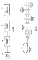
- At least one embodiment of the present invention includes a fiber-based laser source 110 to generate an input laser beam having a first wavelength, a polarization controller 120 having one or more polarization controlling components that receives the input beam, a wavelength converter 130 (e.g.: a wavelength conversion unit) which may include a quasi phase matching (QPM) nonlinear crystal, and an optional phase compensator 140.
- the QPM non-linear crystal may comprise periodically poled lithium niobate (PPLN).
- the fiber-based source 110 is preferred, although other suitable laser sources may be utilized.
- the laser source may comprise one or a combination of a pulsed laser, CW laser, and/or a quasi-CW laser.
- the laser source may comprise a gain switched, q-switched, and/or mode locked source, including a CW or Q-switched mode locked laser.
- the source output is linearly polarized.
- a fiber laser or laser amplifier having a predetermined output polarization state is desirable.
- polarization maintaining (PM) fiber can be used in the fiber laser 110 to maintain the polarization of an output therefrom.
- Rare earth doped fiber is the desirable gain media in the fiber laser or fiber laser amplifier.
- the wavelength converter 130 is sensitive to polarization state at its input (e.g.: pump polarization). For example, when a PPLN crystal is used in the converter and the polarization of the pump light is parallel to polarization of the crystal, the phase matching condition is satisfied. Thus, by using polarization controller 120 to control the polarization state at the input of the wavelength converter 130, one can control the conversion efficiency of the QPM crystal or other conversion element. Thus, the wavelength dependent signal power at the output of the wavelength converter 130 can be varied from maximum available output to near extinction.
- Fig. 1B illustrates an exemplary preferred system, including a non-linear crystal 130a for wavelength conversion, a phase compensator 140-a, and switchable filters for wavelength selection.
- the polarization controller comprises a half wave plate 120-a and an optical isolator is utilized to limit back reflection.
- an optical isolator is utilized to limit back reflection.
- commercially available half wave plates may be utilized. Because a wave plate can be specified with low wedge, the wave plate can be rotated and proper alignment of the optical system can easily be maintained. Operation of the optional phase compensator 140-a will be discussed below.
- Fig. 2 illustrates control of the power (or energy) distribution between pump and signal wavelengths with a polarization controller (e.g.: a zero order half wave plate), with a PPLN crystal for frequency doubling.
- a polarization controller e.g.: a zero order half wave plate
- the half wave plate can change the polarization to any desired angle.
- the field of the pump light parallel to the phase matching polarization direction can be controlled to any value between 0 to A 0 .
- the relative beam power at the respective first (e.g.: pump) and second (e.g.: signal) wavelengths is thereby controlled, as schematically illustrated in plots 210-a, 210-b, and 210-c in Fig. 2 , which schematically represent wavelength spectra of the respective first and second (e.g.: wavelength converted) beams.
- Fig. 3 illustrates measurements obtained with a system according to Fig. 2 .
- an erbium based fiber femtosecond laser oscillator and amplifier were used as the fiber-based laser source.
- the output of laser amplifier provided laser pulse trains in which pulses had a central wavelength at 1610 nm, a pulse duration of about 100 fs, a pulse energy of about 3nJ, and linear polarization.
- a PPLN crystal was used for wavelength conversion.
- a zero order half wave plate was placed between the fiber laser amplifier and the PPLN crystal. The relative power of the pump pulses and the corresponding signal pulses was measured.
- the plot of Fig. 3 shows variation of the signal power and pump power with pump light polarization.
- the signal power was directly measured and pump power was calculated based on signal power.
- the signal power conformed to known angular dependence of SHG generation, as shown by the fit in Fig. 3 .
- the result demonstrates smooth dependence of the signal power over a control range of at least about 100:1.
- the control range may exceed 10:1; a range approaching 1000:1 is achievable, limited by the extinction ratio and polarization purity of system components.
- the pump power is also smoothly controllable over the range, and the modulation of pump power is determined by the maximum conversion efficiency.
- electronic control is desirable, for example via computer remote control (not shown).
- a control function may be generated, sampled or otherwise established at several polarization settings, stored as digital data, and reconstructed for substantially continuous control over the control range, thereby allowing for flexible, high resolution, and high speed control.
- An electronically controllable phase retardation device such as a liquid crystal phase modulator or an electro-optical modulator can be used in such implementations.
- a polarization controlling unit other than a phase retarder could be used, for example a Faraday rotator whose magnetic field is adjustable.
- a power monitoring and a feedback system can be used to automatically control the power distribution to the desired value, and may be further configured as an output stabilizer.
- the relative power distribution among multiple wavelengths may be controlled over a range of at least about 100:1.
- the optional phase compensator 140 may be utilized in various implementations to further control polarization purity. Birefringence of a nonlinear crystal can be a consideration, resulting in phase delay between polarization states light passing through the crystal.
- a phase delay may change the polarization of the light to a different state from the input, for example as presented in Fig. 2 , at 210-c.
- the phase delay may conventionally be compensated using conventional phase retardation components, such as combining of quarter wave plates and half wave plates (not shown), although such compensation adds to system complexity.
- the variation of power ratio between two different polarization states makes the output beam polarization state vary accordingly.
- compensating the phase delay using the conventional phase retarding components is somewhat inconvenient.
- phase delay between these two axes remains constant.
- a birefringent optical component can be used for this purpose, and most preferably will have a sufficiently high non-linear threshold, or otherwise be configured, to avoid wavelength shifting.
- the non-linear crystal 410 and phase compensation crystal 420 are characterized, in part, by their respective thickness, and the respective index difference seen along the S and P directions.
- the phase compensator has the same optical axis, or parallel optical axis of opposite sign, relative to that of the nonlinear crystal
- the thickness of the compensator 420 will be preset to give the same value of phase delay while being opposite in sign to the optical axis of the nonlinear crystal.
- the compensator can recover the polarization state to the incident state. Recovery is not affected by power ratio variation, and it will not affect the signal light because the polarization of the signal light is parallel to the optical axis of the nonlinear crystal and the compensator. Thus, separation of pump and signal light is not necessary.
- the phase compensator could be an optic with preselected thickness, or it can be formed by two pieces with prism shape 420-a as shown in Fig. 4B .
- the latter arrangement allows pre-adjusting the thickness of the compensator to match the delay caused by the nonlinear crystal.
- an active device may be utilized, such as an EO component.
- the phase delay need not be adjusted after the laser system is aligned.
- adjustment mechanisms may be provided, and may be preferred to achieve additional benefits, such as manipulating the polarization state of the laser system output.
- a wavelength selective filter can be placed downstream from the wavelength converter, which can selectively allow either the pump light or the signal light, or both, to be output from the laser source. If only one of the pump and signal are to be output, the polarization controlling component and the wavelength converter can be used as a power adjuster and/or power stabilizer.
- the pump and signal were arranged for operation in a two-wavelength system.
- embodiments of the present invention are not restricted to only two wavelength operation.
- several non-linear processes are available for wavelength conversion, and embodiments utilizing such processes are within the scope of the present invention.
- the polarization control and phase compensation techniques may be adapted for use with more than two output wavelengths. For example, if an idler wavelength differs from either the pump wavelength or the signal wavelength, and is generated in the wavelength converter, the dual wavelength laser system can be arranged as a triple wavelength light source. Numerous options may be utilized to provide a multi-wavelength pulsed laser source.
- a DPSS Q-switched laser may be utilized to generate input pulses, and may optionally be combined with a fiber laser and/or amplifier.
- a CW or quasi-CW source may be utilized, including fiber lasers and/or long pulse diode sources.
- wavelength shifting is not restricted to harmonic generation, and may be carried out with other suitable non-linear processes.
- nonlinear crystals such as QPM crystals (e.g.: PPLN) or non-critical phase matched crystals (e.g.: LBO) may be utilized, and such crystals may exhibit a wavelength dependent response to temperature.
- non-polarized inputs may be generated and converted to polarized beams with suitable optics.
- a polarization controller may be adjusted during laser system fabrication to provide a preset polarization and output wavelengths for operation, without field adjustment.
- a control unit may be provided for flexible operation over a desirable control range.
Landscapes
- Physics & Mathematics (AREA)
- Electromagnetism (AREA)
- Optics & Photonics (AREA)
- Engineering & Computer Science (AREA)
- Plasma & Fusion (AREA)
- Nonlinear Science (AREA)
- General Physics & Mathematics (AREA)
- Optical Modulation, Optical Deflection, Nonlinear Optics, Optical Demodulation, Optical Logic Elements (AREA)
- Lasers (AREA)
Claims (15)
- Système laser, comprenant :une source laser (110) qui génère un faisceau d'entrée ayant une première longueur d'onde ;un contrôleur de polarisation (120) ayant un ou plusieurs composants de contrôle de polarisation, qui reçoit le faisceau d'entrée, le contrôleur de polarisation (120) devant contrôler une polarisation du faisceau d'entrée ; etun convertisseur de longueur d'onde (130) qui reçoit le faisceau d'entrée du contrôleur de polarisation à une première longueur d'onde et génère un faisceau ayant subi une conversion de longueur d'onde dans lequel au moins une partie de la puissance du faisceau à la première longueur d'onde est convertie en une puissance de faisceau à une seconde longueur d'onde ;dans lequel le convertisseur de longueur d'onde (130) comprend un cristal non linéaire sensible à la polarisation, le cristal non linéaire sensible à la polarisation provoquant un retard de phase entre des états de polarisation de lumière de la première longueur d'onde passant à travers le cristal ;dans lequel le contrôleur de polarisation (120) est agencé de telle manière que la puissance relative au niveau de chacune des première et seconde longueurs d'onde est contrôlable, et la sortie du système laser comprend une puissance de signal aux deux des première et seconde longueurs d'onde ; etun compensateur de phase optique (140) disposé en aval du convertisseur de longueur d'onde (130), le compensateur de phase optique (140) étant un composant optique biréfringent et ayant le même axe optique ou un axe optique parallèle de signe opposé, par rapport à celui du cristal non linéaire et une épaisseur qui est définie pour donner la même valeur de retard de phase que le cristal non linéaire bien qu'étant de signe opposé.
- Système laser selon la revendication 1, dans lequel la source laser (110) comprend l'une d'une fibre optique dopée aux terres rares ou d'une fibre de maintien de polarisation.
- Système laser selon la revendication 1, dans lequel la source laser (110) comprend un laser pulsé qui génère un faisceau laser pulsé ayant au moins une largeur d'impulsion de l'ordre de la femtoseconde à la picoseconde, dans lequel la puissance relative de l'entrée correspondante et des impulsions ayant subi une conversion de longueur d'onde aux première et seconde longueurs d'ondes respectives est contrôlable à l'aide du contrôleur de polarisation (120).
- Système laser selon la revendication 1, dans lequel le contrôleur de polarisation (120) comprend l'un d'un retardateur de phase cristalline liquide ou d'un rotateur de Faraday contrôlable.
- Système laser selon la revendication 1, dans lequel le composant biréfringent comprend l'un d'une fibre de maintien de polarisation, de deux éléments ayant une forme prismatique ou d'un retardateur de phase active, dans lequel le retardateur de phase active comprend un modulateur de phase électrooptique.
- Système laser selon la revendication 1, dans lequel un ou plusieurs filtres sélectifs de longueur d'onde sont disposés en aval du convertisseur de longueur d'onde (130) pour contrôler la fraction d'énergie de sortie des première et seconde longueurs d'onde.
- Système laser selon la revendication 1, dans lequel la source laser pulsée (110) comprend un laser à fibre et/ou un amplificateur.
- Système laser selon la revendication 1, comprenant en outre un contrôleur à rétroaction pour stabiliser la puissance laser de sortie.
- Système laser selon la revendication 1, dans lequel l'efficacité de la conversion de longueur d'onde du cristal non linéaire est déterminée par adaptation de phase.
- Système laser selon la revendication 9, dans lequel ladite adaptation de phase est une quasi-adaptation de phase à l'aide d'un cristal non linéaire ayant subi une quasi-adaptation de phase comprenant du niobate de lithium périodiquement polarisé (PPLN).
- Système laser selon la revendication 9, dans lequel ladite adaptation de phase est une adaptation de phase non critique à l'aide d'un cristal non linéaire ayant subi une adaptation de phase non critique comprenant du triborate de lithium (LBO).
- Système laser selon la revendication 1, comprenant :un filtre sélectif spectral pour sélectionner la première longueur d'onde ou bien la seconde longueur d'onde.
- Système laser selon la revendication 1 ou 12, dans lequel la distribution de puissance est contrôlable sur une plage d'au moins environ 10:1.
- Système de déclenchement temporel de mesures de pompe et de sonde, comprenant le système laser selon la revendication 1 ou 12, dans lequel la première longueur d'onde est une longueur d'onde de pompe et la seconde longueur d'onde est une longueur d'onde de signal, dans lequel l'énergie à la première longueur d'onde est utilisée pour exciter un objet et l'énergie à la seconde longueur d'onde est utilisée en tant que sonde, ou vice versa.
- Système de traitement de matériau comprenant le système laser selon la revendication 1 ou 12, dans lequel l'énergie à la première longueur d'onde est utilisée pour prétraiter un matériau cible et l'énergie à la seconde longueur d'onde est utilisée pour traiter davantage le matériau cible.
Applications Claiming Priority (2)
| Application Number | Priority Date | Filing Date | Title |
|---|---|---|---|
| US201161534669P | 2011-09-14 | 2011-09-14 | |
| PCT/US2012/053899 WO2013039756A1 (fr) | 2011-09-14 | 2012-09-06 | Source laser contrôlable à fibre multi-longueur d'onde |
Publications (3)
| Publication Number | Publication Date |
|---|---|
| EP2756342A1 EP2756342A1 (fr) | 2014-07-23 |
| EP2756342A4 EP2756342A4 (fr) | 2014-09-17 |
| EP2756342B1 true EP2756342B1 (fr) | 2016-11-30 |
Family
ID=47883621
Family Applications (1)
| Application Number | Title | Priority Date | Filing Date |
|---|---|---|---|
| EP12831411.9A Not-in-force EP2756342B1 (fr) | 2011-09-14 | 2012-09-06 | Source laser contrôlable à fibre multi-longueur d'onde |
Country Status (5)
| Country | Link |
|---|---|
| US (2) | US8976823B2 (fr) |
| EP (1) | EP2756342B1 (fr) |
| JP (1) | JP2014530493A (fr) |
| CN (1) | CN103814317A (fr) |
| WO (1) | WO2013039756A1 (fr) |
Families Citing this family (19)
| Publication number | Priority date | Publication date | Assignee | Title |
|---|---|---|---|---|
| CN103814317A (zh) * | 2011-09-14 | 2014-05-21 | Imra美国公司 | 可控的多波长光纤激光源 |
| US9634454B1 (en) | 2012-01-17 | 2017-04-25 | President And Fellows Of Harvard College | Laser illumination systems and methods for dual-excitation wavelength non-linear optical microscopy and micro-spectroscopy systems |
| US8792156B1 (en) | 2012-01-17 | 2014-07-29 | President And Fellows Of Harvard College | Laser illumination systems and methods for dual-excitation wavelength non-linear optical microscopy and micro-spectroscopy systems |
| US9429850B2 (en) * | 2012-03-05 | 2016-08-30 | Nikon Corporation | Laser device, and exposure device and inspection device provided with laser device |
| JP2017504074A (ja) * | 2014-01-07 | 2017-02-02 | ソーラボス インコーポレイテッド | 可変フェムト秒発振器を使用する調節可能中赤外スーパー・コンティニューム発生装置 |
| US9841655B2 (en) * | 2015-07-01 | 2017-12-12 | Kla-Tencor Corporation | Power scalable nonlinear optical wavelength converter |
| CN105562925A (zh) * | 2016-01-28 | 2016-05-11 | 广东正业科技股份有限公司 | 一种co2激光切割设备及其光路传输方法 |
| US10824047B2 (en) | 2016-03-14 | 2020-11-03 | AOSense, Inc. | Optical comb carrier envelope-offset frequency control using intensity modulation |
| EP3469669A4 (fr) * | 2016-06-03 | 2020-02-19 | Km Labs Inc. | Utilisation d'éléments de polarisation à commande électronique pour le lancement et l'optimisation d'une synchronisation des modes d'un laser |
| US10012843B2 (en) * | 2016-07-13 | 2018-07-03 | Sharp Kabushiki Kaisha | Compact and effective beam absorber for frequency converted laser |
| KR101944899B1 (ko) * | 2016-12-22 | 2019-02-01 | 주식회사 포스코 | 방향성 전기강판의 자구미세화 방법 |
| CN107332103B (zh) * | 2017-06-22 | 2019-04-05 | 四川大学 | 一种双波长交替调q激光器及其激光输出方法 |
| CN109375448B (zh) * | 2018-09-14 | 2020-11-20 | 华东师范大学 | 一种基于频率上转换技术的偏振控制器及其工作方法 |
| CN109378694B (zh) * | 2018-12-20 | 2020-07-24 | 北京航空航天大学 | 宽带波长可调色散管理型全光纤超快脉冲激光器及系统 |
| CN110064838B (zh) * | 2019-03-29 | 2020-11-20 | 江苏大学 | 一种基于同一激光器获得多种钣金成形效果的激光加工方法 |
| LT6791B (lt) * | 2019-05-15 | 2020-12-28 | Uab "Altechna R&D" | Skaidrių medžiagų apdirbimo būdas ir įrenginys |
| CN110262054B (zh) * | 2019-06-26 | 2021-09-07 | 中国空间技术研究院 | 一种宽带高分辨率大动态范围延时补偿系统及方法 |
| LT3800503T (lt) * | 2019-10-01 | 2023-11-27 | Fastlite | Be kompresijos ir vieno spindulio nešančios bangos - kontūro stabilios fazės optinių impulsų generavimas |
| DE102020206636B3 (de) * | 2020-05-27 | 2021-07-01 | Fraunhofer-Gesellschaft zur Förderung der angewandten Forschung eingetragener Verein | Laseranordnung und Verfahren zum Steuern einer Laseranordnung |
Family Cites Families (26)
| Publication number | Priority date | Publication date | Assignee | Title |
|---|---|---|---|---|
| JPH02125233A (ja) * | 1988-11-02 | 1990-05-14 | Pioneer Electron Corp | ファイバー型光波長変換装置 |
| US5099147A (en) * | 1990-11-05 | 1992-03-24 | Hughes Aircraft Company | Raman converter with variable wavelength distribution |
| JPH0676335A (ja) * | 1992-08-31 | 1994-03-18 | Sanyo Electric Co Ltd | 光記録・再生・消去装置 |
| US5361268A (en) * | 1993-05-18 | 1994-11-01 | Electro Scientific Industries, Inc. | Switchable two-wavelength frequency-converting laser system and power control therefor |
| US5611946A (en) * | 1994-02-18 | 1997-03-18 | New Wave Research | Multi-wavelength laser system, probe station and laser cutter system using the same |
| US5778016A (en) * | 1994-04-01 | 1998-07-07 | Imra America, Inc. | Scanning temporal ultrafast delay methods and apparatuses therefor |
| US5450427A (en) | 1994-10-21 | 1995-09-12 | Imra America, Inc. | Technique for the generation of optical pulses in modelocked lasers by dispersive control of the oscillation pulse width |
| US5847863A (en) | 1996-04-25 | 1998-12-08 | Imra America, Inc. | Hybrid short-pulse amplifiers with phase-mismatch compensated pulse stretchers and compressors |
| US5862287A (en) | 1996-12-13 | 1999-01-19 | Imra America, Inc. | Apparatus and method for delivery of dispersion compensated ultrashort optical pulses with high peak power |
| US5880877A (en) * | 1997-01-28 | 1999-03-09 | Imra America, Inc. | Apparatus and method for the generation of high-power femtosecond pulses from a fiber amplifier |
| US6181463B1 (en) | 1997-03-21 | 2001-01-30 | Imra America, Inc. | Quasi-phase-matched parametric chirped pulse amplification systems |
| US6208458B1 (en) | 1997-03-21 | 2001-03-27 | Imra America, Inc. | Quasi-phase-matched parametric chirped pulse amplification systems |
| US6198568B1 (en) | 1997-04-25 | 2001-03-06 | Imra America, Inc. | Use of Chirped Quasi-phase-matched materials in chirped pulse amplification systems |
| US5818630A (en) | 1997-06-25 | 1998-10-06 | Imra America, Inc. | Single-mode amplifiers and compressors based on multi-mode fibers |
| US6154310A (en) | 1997-11-21 | 2000-11-28 | Imra America, Inc. | Ultrashort-pulse source with controllable multiple-wavelength output |
| US6744555B2 (en) | 1997-11-21 | 2004-06-01 | Imra America, Inc. | Ultrashort-pulse source with controllable wavelength output |
| US6885683B1 (en) | 2000-05-23 | 2005-04-26 | Imra America, Inc. | Modular, high energy, widely-tunable ultrafast fiber source |
| US6785040B2 (en) * | 2001-08-17 | 2004-08-31 | Bae Systems Information And Electronic Systems Integration Inc. | Spectral modulation in an optical wavelength converter |
| JP2003290963A (ja) * | 2002-03-29 | 2003-10-14 | Sumitomo Heavy Ind Ltd | レーザ装置、レーザ加工装置及びレーザ加工方法 |
| US7804864B2 (en) * | 2004-03-31 | 2010-09-28 | Imra America, Inc. | High power short pulse fiber laser |
| US7508853B2 (en) * | 2004-12-07 | 2009-03-24 | Imra, America, Inc. | Yb: and Nd: mode-locked oscillators and fiber systems incorporated in solid-state short pulse laser systems |
| WO2007046833A2 (fr) * | 2004-12-20 | 2007-04-26 | Imra America, Inc. | Source laser a impulsions avec compresseur a reseau ajustable |
| US9138913B2 (en) * | 2005-09-08 | 2015-09-22 | Imra America, Inc. | Transparent material processing with an ultrashort pulse laser |
| US7529281B2 (en) * | 2006-07-11 | 2009-05-05 | Mobius Photonics, Inc. | Light source with precisely controlled wavelength-converted average power |
| US8199398B2 (en) * | 2008-02-07 | 2012-06-12 | Imra America, Inc. | High power parallel fiber arrays |
| CN103814317A (zh) * | 2011-09-14 | 2014-05-21 | Imra美国公司 | 可控的多波长光纤激光源 |
-
2012
- 2012-09-06 CN CN201280042229.0A patent/CN103814317A/zh active Pending
- 2012-09-06 JP JP2014530701A patent/JP2014530493A/ja active Pending
- 2012-09-06 WO PCT/US2012/053899 patent/WO2013039756A1/fr active Application Filing
- 2012-09-06 EP EP12831411.9A patent/EP2756342B1/fr not_active Not-in-force
- 2012-09-12 US US13/611,646 patent/US8976823B2/en active Active
-
2015
- 2015-02-09 US US14/617,028 patent/US9407056B2/en not_active Expired - Fee Related
Also Published As
| Publication number | Publication date |
|---|---|
| US20130064256A1 (en) | 2013-03-14 |
| EP2756342A4 (fr) | 2014-09-17 |
| EP2756342A1 (fr) | 2014-07-23 |
| US20150180194A1 (en) | 2015-06-25 |
| US8976823B2 (en) | 2015-03-10 |
| JP2014530493A (ja) | 2014-11-17 |
| WO2013039756A1 (fr) | 2013-03-21 |
| CN103814317A (zh) | 2014-05-21 |
| US9407056B2 (en) | 2016-08-02 |
Similar Documents
| Publication | Publication Date | Title |
|---|---|---|
| EP2756342B1 (fr) | Source laser contrôlable à fibre multi-longueur d'onde | |
| US6862131B2 (en) | Laser light generating apparatus and method | |
| JP2021524060A (ja) | レーザビームの方法及びシステム | |
| KR20080088440A (ko) | 레이저광 발생 장치 | |
| US20070071060A1 (en) | Interferometer, in particular for determining and stabilizing the relative phase of short pulses | |
| KR20170026451A (ko) | 초단파 고출력 및/또는 고에너지 펄스들을 갖는 uv가시광선 레이저 시스템 | |
| US9036249B2 (en) | Method of sum-frequency conversion and frequency converter with optical active rotator | |
| CN106489220A (zh) | 用于使激光装置进行工作的方法、谐振器配置和移相器的使用 | |
| WO1994024735A1 (fr) | Amplificateurs et oscillateurs parametriques optiques pompes par lasers accordables | |
| JP2006330518A (ja) | 高調波発生装置 | |
| EP4002610A1 (fr) | Dispositif laser et procédé de génération de lumière laser | |
| CN109375448B (zh) | 一种基于频率上转换技术的偏振控制器及其工作方法 | |
| EP3646112B1 (fr) | Modulateur électro-optique | |
| JP2000295175A (ja) | 光リモートアンテナ | |
| US11552442B2 (en) | Device and method for generating laser pulses by Kerr lens based mode locking with a loss-modulation device as a Kerr medium | |
| EP3729192B1 (fr) | Générateur de lumière comprimée et procédé de génération de lumière comprimée | |
| JP2000338531A (ja) | 波長変換レーザ装置及びレーザレーダ装置 | |
| JP2011053314A (ja) | 光源装置 | |
| Yan-Ling et al. | Efficient collinear frequency tripling of femtosecond laser with compensation of group velocity delay | |
| Zhao et al. | Control of femtosecond pulse filament formation in air through variation of the initial chirp of the pulse | |
| TW466810B (en) | Solid-state tunable visible laser source using sum frequency mixing or frequency doubling of a Yb:SILICA fiber laser and an Nd:YAG laser | |
| US20120176666A1 (en) | Laser apparatus and method to generate uv laser light | |
| JP2003315859A (ja) | 波長変換レーザ装置 | |
| Zhao et al. | Tunable dual-signal PPLN optical parametric generator by using an acousto-optic beam splitter | |
| Lienhart et al. | Fibered laser system for rubidium laser cooling based on telecom technology at 1560 nm and frequency doubling |
Legal Events
| Date | Code | Title | Description |
|---|---|---|---|
| PUAI | Public reference made under article 153(3) epc to a published international application that has entered the european phase |
Free format text: ORIGINAL CODE: 0009012 |
|
| 17P | Request for examination filed |
Effective date: 20140311 |
|
| AK | Designated contracting states |
Kind code of ref document: A1 Designated state(s): AL AT BE BG CH CY CZ DE DK EE ES FI FR GB GR HR HU IE IS IT LI LT LU LV MC MK MT NL NO PL PT RO RS SE SI SK SM TR |
|
| A4 | Supplementary search report drawn up and despatched |
Effective date: 20140821 |
|
| RIC1 | Information provided on ipc code assigned before grant |
Ipc: G02F 1/35 20060101AFI20140813BHEP Ipc: B23K 26/00 20140101ALN20140813BHEP Ipc: H01S 3/10 20060101ALN20140813BHEP Ipc: H01S 3/067 20060101ALN20140813BHEP |
|
| DAX | Request for extension of the european patent (deleted) | ||
| 17Q | First examination report despatched |
Effective date: 20150529 |
|
| REG | Reference to a national code |
Ref country code: DE Ref legal event code: R079 Ref document number: 602012026150 Country of ref document: DE Free format text: PREVIOUS MAIN CLASS: G02B0006350000 Ipc: G02F0001350000 |
|
| RIC1 | Information provided on ipc code assigned before grant |
Ipc: B23K 26/00 20140101ALN20160415BHEP Ipc: G02F 1/35 20060101AFI20160415BHEP Ipc: H01S 3/10 20060101ALN20160415BHEP Ipc: H01S 3/067 20060101ALN20160415BHEP Ipc: H01S 3/00 20060101ALI20160415BHEP |
|
| GRAP | Despatch of communication of intention to grant a patent |
Free format text: ORIGINAL CODE: EPIDOSNIGR1 |
|
| INTG | Intention to grant announced |
Effective date: 20160627 |
|
| GRAS | Grant fee paid |
Free format text: ORIGINAL CODE: EPIDOSNIGR3 |
|
| GRAA | (expected) grant |
Free format text: ORIGINAL CODE: 0009210 |
|
| AK | Designated contracting states |
Kind code of ref document: B1 Designated state(s): AL AT BE BG CH CY CZ DE DK EE ES FI FR GB GR HR HU IE IS IT LI LT LU LV MC MK MT NL NO PL PT RO RS SE SI SK SM TR |
|
| REG | Reference to a national code |
Ref country code: CH Ref legal event code: EP Ref country code: GB Ref legal event code: FG4D |
|
| REG | Reference to a national code |
Ref country code: AT Ref legal event code: REF Ref document number: 850350 Country of ref document: AT Kind code of ref document: T Effective date: 20161215 |
|
| REG | Reference to a national code |
Ref country code: IE Ref legal event code: FG4D |
|
| REG | Reference to a national code |
Ref country code: DE Ref legal event code: R096 Ref document number: 602012026150 Country of ref document: DE |
|
| PG25 | Lapsed in a contracting state [announced via postgrant information from national office to epo] |
Ref country code: LV Free format text: LAPSE BECAUSE OF FAILURE TO SUBMIT A TRANSLATION OF THE DESCRIPTION OR TO PAY THE FEE WITHIN THE PRESCRIBED TIME-LIMIT Effective date: 20161130 |
|
| REG | Reference to a national code |
Ref country code: LT Ref legal event code: MG4D |
|
| REG | Reference to a national code |
Ref country code: NL Ref legal event code: MP Effective date: 20161130 |
|
| REG | Reference to a national code |
Ref country code: AT Ref legal event code: MK05 Ref document number: 850350 Country of ref document: AT Kind code of ref document: T Effective date: 20161130 |
|
| PG25 | Lapsed in a contracting state [announced via postgrant information from national office to epo] |
Ref country code: GR Free format text: LAPSE BECAUSE OF FAILURE TO SUBMIT A TRANSLATION OF THE DESCRIPTION OR TO PAY THE FEE WITHIN THE PRESCRIBED TIME-LIMIT Effective date: 20170301 Ref country code: NO Free format text: LAPSE BECAUSE OF FAILURE TO SUBMIT A TRANSLATION OF THE DESCRIPTION OR TO PAY THE FEE WITHIN THE PRESCRIBED TIME-LIMIT Effective date: 20170228 Ref country code: LT Free format text: LAPSE BECAUSE OF FAILURE TO SUBMIT A TRANSLATION OF THE DESCRIPTION OR TO PAY THE FEE WITHIN THE PRESCRIBED TIME-LIMIT Effective date: 20161130 Ref country code: SE Free format text: LAPSE BECAUSE OF FAILURE TO SUBMIT A TRANSLATION OF THE DESCRIPTION OR TO PAY THE FEE WITHIN THE PRESCRIBED TIME-LIMIT Effective date: 20161130 |
|
| PG25 | Lapsed in a contracting state [announced via postgrant information from national office to epo] |
Ref country code: PL Free format text: LAPSE BECAUSE OF FAILURE TO SUBMIT A TRANSLATION OF THE DESCRIPTION OR TO PAY THE FEE WITHIN THE PRESCRIBED TIME-LIMIT Effective date: 20161130 Ref country code: HR Free format text: LAPSE BECAUSE OF FAILURE TO SUBMIT A TRANSLATION OF THE DESCRIPTION OR TO PAY THE FEE WITHIN THE PRESCRIBED TIME-LIMIT Effective date: 20161130 Ref country code: AT Free format text: LAPSE BECAUSE OF FAILURE TO SUBMIT A TRANSLATION OF THE DESCRIPTION OR TO PAY THE FEE WITHIN THE PRESCRIBED TIME-LIMIT Effective date: 20161130 Ref country code: FI Free format text: LAPSE BECAUSE OF FAILURE TO SUBMIT A TRANSLATION OF THE DESCRIPTION OR TO PAY THE FEE WITHIN THE PRESCRIBED TIME-LIMIT Effective date: 20161130 Ref country code: RS Free format text: LAPSE BECAUSE OF FAILURE TO SUBMIT A TRANSLATION OF THE DESCRIPTION OR TO PAY THE FEE WITHIN THE PRESCRIBED TIME-LIMIT Effective date: 20161130 Ref country code: PT Free format text: LAPSE BECAUSE OF FAILURE TO SUBMIT A TRANSLATION OF THE DESCRIPTION OR TO PAY THE FEE WITHIN THE PRESCRIBED TIME-LIMIT Effective date: 20170330 Ref country code: ES Free format text: LAPSE BECAUSE OF FAILURE TO SUBMIT A TRANSLATION OF THE DESCRIPTION OR TO PAY THE FEE WITHIN THE PRESCRIBED TIME-LIMIT Effective date: 20161130 |
|
| PG25 | Lapsed in a contracting state [announced via postgrant information from national office to epo] |
Ref country code: NL Free format text: LAPSE BECAUSE OF FAILURE TO SUBMIT A TRANSLATION OF THE DESCRIPTION OR TO PAY THE FEE WITHIN THE PRESCRIBED TIME-LIMIT Effective date: 20161130 |
|
| PG25 | Lapsed in a contracting state [announced via postgrant information from national office to epo] |
Ref country code: RO Free format text: LAPSE BECAUSE OF FAILURE TO SUBMIT A TRANSLATION OF THE DESCRIPTION OR TO PAY THE FEE WITHIN THE PRESCRIBED TIME-LIMIT Effective date: 20161130 Ref country code: EE Free format text: LAPSE BECAUSE OF FAILURE TO SUBMIT A TRANSLATION OF THE DESCRIPTION OR TO PAY THE FEE WITHIN THE PRESCRIBED TIME-LIMIT Effective date: 20161130 Ref country code: CZ Free format text: LAPSE BECAUSE OF FAILURE TO SUBMIT A TRANSLATION OF THE DESCRIPTION OR TO PAY THE FEE WITHIN THE PRESCRIBED TIME-LIMIT Effective date: 20161130 Ref country code: DK Free format text: LAPSE BECAUSE OF FAILURE TO SUBMIT A TRANSLATION OF THE DESCRIPTION OR TO PAY THE FEE WITHIN THE PRESCRIBED TIME-LIMIT Effective date: 20161130 Ref country code: SK Free format text: LAPSE BECAUSE OF FAILURE TO SUBMIT A TRANSLATION OF THE DESCRIPTION OR TO PAY THE FEE WITHIN THE PRESCRIBED TIME-LIMIT Effective date: 20161130 |
|
| PG25 | Lapsed in a contracting state [announced via postgrant information from national office to epo] |
Ref country code: BE Free format text: LAPSE BECAUSE OF FAILURE TO SUBMIT A TRANSLATION OF THE DESCRIPTION OR TO PAY THE FEE WITHIN THE PRESCRIBED TIME-LIMIT Effective date: 20161130 Ref country code: IT Free format text: LAPSE BECAUSE OF FAILURE TO SUBMIT A TRANSLATION OF THE DESCRIPTION OR TO PAY THE FEE WITHIN THE PRESCRIBED TIME-LIMIT Effective date: 20161130 Ref country code: BG Free format text: LAPSE BECAUSE OF FAILURE TO SUBMIT A TRANSLATION OF THE DESCRIPTION OR TO PAY THE FEE WITHIN THE PRESCRIBED TIME-LIMIT Effective date: 20170228 Ref country code: SM Free format text: LAPSE BECAUSE OF FAILURE TO SUBMIT A TRANSLATION OF THE DESCRIPTION OR TO PAY THE FEE WITHIN THE PRESCRIBED TIME-LIMIT Effective date: 20161130 |
|
| REG | Reference to a national code |
Ref country code: DE Ref legal event code: R097 Ref document number: 602012026150 Country of ref document: DE |
|
| REG | Reference to a national code |
Ref country code: FR Ref legal event code: PLFP Year of fee payment: 6 |
|
| PLBE | No opposition filed within time limit |
Free format text: ORIGINAL CODE: 0009261 |
|
| STAA | Information on the status of an ep patent application or granted ep patent |
Free format text: STATUS: NO OPPOSITION FILED WITHIN TIME LIMIT |
|
| PGFP | Annual fee paid to national office [announced via postgrant information from national office to epo] |
Ref country code: FR Payment date: 20170925 Year of fee payment: 6 |
|
| 26N | No opposition filed |
Effective date: 20170831 |
|
| PG25 | Lapsed in a contracting state [announced via postgrant information from national office to epo] |
Ref country code: SI Free format text: LAPSE BECAUSE OF FAILURE TO SUBMIT A TRANSLATION OF THE DESCRIPTION OR TO PAY THE FEE WITHIN THE PRESCRIBED TIME-LIMIT Effective date: 20161130 |
|
| PGFP | Annual fee paid to national office [announced via postgrant information from national office to epo] |
Ref country code: DE Payment date: 20171122 Year of fee payment: 6 |
|
| REG | Reference to a national code |
Ref country code: CH Ref legal event code: PL |
|
| GBPC | Gb: european patent ceased through non-payment of renewal fee |
Effective date: 20170906 |
|
| PG25 | Lapsed in a contracting state [announced via postgrant information from national office to epo] |
Ref country code: MC Free format text: LAPSE BECAUSE OF FAILURE TO SUBMIT A TRANSLATION OF THE DESCRIPTION OR TO PAY THE FEE WITHIN THE PRESCRIBED TIME-LIMIT Effective date: 20161130 |
|
| REG | Reference to a national code |
Ref country code: IE Ref legal event code: MM4A |
|
| PG25 | Lapsed in a contracting state [announced via postgrant information from national office to epo] |
Ref country code: LU Free format text: LAPSE BECAUSE OF NON-PAYMENT OF DUE FEES Effective date: 20170906 |
|
| PG25 | Lapsed in a contracting state [announced via postgrant information from national office to epo] |
Ref country code: CH Free format text: LAPSE BECAUSE OF NON-PAYMENT OF DUE FEES Effective date: 20170930 Ref country code: IE Free format text: LAPSE BECAUSE OF NON-PAYMENT OF DUE FEES Effective date: 20170906 Ref country code: GB Free format text: LAPSE BECAUSE OF NON-PAYMENT OF DUE FEES Effective date: 20170906 Ref country code: LI Free format text: LAPSE BECAUSE OF NON-PAYMENT OF DUE FEES Effective date: 20170930 |
|
| PG25 | Lapsed in a contracting state [announced via postgrant information from national office to epo] |
Ref country code: MT Free format text: LAPSE BECAUSE OF NON-PAYMENT OF DUE FEES Effective date: 20170906 |
|
| REG | Reference to a national code |
Ref country code: DE Ref legal event code: R119 Ref document number: 602012026150 Country of ref document: DE |
|
| PG25 | Lapsed in a contracting state [announced via postgrant information from national office to epo] |
Ref country code: HU Free format text: LAPSE BECAUSE OF FAILURE TO SUBMIT A TRANSLATION OF THE DESCRIPTION OR TO PAY THE FEE WITHIN THE PRESCRIBED TIME-LIMIT; INVALID AB INITIO Effective date: 20120906 |
|
| PG25 | Lapsed in a contracting state [announced via postgrant information from national office to epo] |
Ref country code: DE Free format text: LAPSE BECAUSE OF NON-PAYMENT OF DUE FEES Effective date: 20190402 |
|
| PG25 | Lapsed in a contracting state [announced via postgrant information from national office to epo] |
Ref country code: FR Free format text: LAPSE BECAUSE OF NON-PAYMENT OF DUE FEES Effective date: 20180930 |
|
| PG25 | Lapsed in a contracting state [announced via postgrant information from national office to epo] |
Ref country code: CY Free format text: LAPSE BECAUSE OF NON-PAYMENT OF DUE FEES Effective date: 20161130 |
|
| PG25 | Lapsed in a contracting state [announced via postgrant information from national office to epo] |
Ref country code: MK Free format text: LAPSE BECAUSE OF FAILURE TO SUBMIT A TRANSLATION OF THE DESCRIPTION OR TO PAY THE FEE WITHIN THE PRESCRIBED TIME-LIMIT Effective date: 20161130 |
|
| PG25 | Lapsed in a contracting state [announced via postgrant information from national office to epo] |
Ref country code: TR Free format text: LAPSE BECAUSE OF FAILURE TO SUBMIT A TRANSLATION OF THE DESCRIPTION OR TO PAY THE FEE WITHIN THE PRESCRIBED TIME-LIMIT Effective date: 20161130 |
|
| PG25 | Lapsed in a contracting state [announced via postgrant information from national office to epo] |
Ref country code: AL Free format text: LAPSE BECAUSE OF FAILURE TO SUBMIT A TRANSLATION OF THE DESCRIPTION OR TO PAY THE FEE WITHIN THE PRESCRIBED TIME-LIMIT Effective date: 20161130 Ref country code: IS Free format text: LAPSE BECAUSE OF FAILURE TO SUBMIT A TRANSLATION OF THE DESCRIPTION OR TO PAY THE FEE WITHIN THE PRESCRIBED TIME-LIMIT Effective date: 20170330 |