EP2754884A1 - Obturateur de rayonnement haute fréquence - Google Patents
Obturateur de rayonnement haute fréquence Download PDFInfo
- Publication number
- EP2754884A1 EP2754884A1 EP12829239.8A EP12829239A EP2754884A1 EP 2754884 A1 EP2754884 A1 EP 2754884A1 EP 12829239 A EP12829239 A EP 12829239A EP 2754884 A1 EP2754884 A1 EP 2754884A1
- Authority
- EP
- European Patent Office
- Prior art keywords
- casing
- emission
- conductor
- plug
- high frequency
- Prior art date
- Legal status (The legal status is an assumption and is not a legal conclusion. Google has not performed a legal analysis and makes no representation as to the accuracy of the status listed.)
- Withdrawn
Links
Images


Classifications
-
- H—ELECTRICITY
- H01—ELECTRIC ELEMENTS
- H01T—SPARK GAPS; OVERVOLTAGE ARRESTERS USING SPARK GAPS; SPARKING PLUGS; CORONA DEVICES; GENERATING IONS TO BE INTRODUCED INTO NON-ENCLOSED GASES
- H01T13/00—Sparking plugs
- H01T13/20—Sparking plugs characterised by features of the electrodes or insulation
-
- F—MECHANICAL ENGINEERING; LIGHTING; HEATING; WEAPONS; BLASTING
- F02—COMBUSTION ENGINES; HOT-GAS OR COMBUSTION-PRODUCT ENGINE PLANTS
- F02P—IGNITION, OTHER THAN COMPRESSION IGNITION, FOR INTERNAL-COMBUSTION ENGINES; TESTING OF IGNITION TIMING IN COMPRESSION-IGNITION ENGINES
- F02P23/00—Other ignition
- F02P23/04—Other physical ignition means, e.g. using laser rays
- F02P23/045—Other physical ignition means, e.g. using laser rays using electromagnetic microwaves
-
- H—ELECTRICITY
- H01—ELECTRIC ELEMENTS
- H01T—SPARK GAPS; OVERVOLTAGE ARRESTERS USING SPARK GAPS; SPARKING PLUGS; CORONA DEVICES; GENERATING IONS TO BE INTRODUCED INTO NON-ENCLOSED GASES
- H01T13/00—Sparking plugs
- H01T13/50—Sparking plugs having means for ionisation of gap
-
- H—ELECTRICITY
- H05—ELECTRIC TECHNIQUES NOT OTHERWISE PROVIDED FOR
- H05H—PLASMA TECHNIQUE; PRODUCTION OF ACCELERATED ELECTRICALLY-CHARGED PARTICLES OR OF NEUTRONS; PRODUCTION OR ACCELERATION OF NEUTRAL MOLECULAR OR ATOMIC BEAMS
- H05H1/00—Generating plasma; Handling plasma
- H05H1/24—Generating plasma
- H05H1/46—Generating plasma using applied electromagnetic fields, e.g. high frequency or microwave energy
- H05H1/461—Microwave discharges
- H05H1/463—Microwave discharges using antennas or applicators
-
- F—MECHANICAL ENGINEERING; LIGHTING; HEATING; WEAPONS; BLASTING
- F02—COMBUSTION ENGINES; HOT-GAS OR COMBUSTION-PRODUCT ENGINE PLANTS
- F02P—IGNITION, OTHER THAN COMPRESSION IGNITION, FOR INTERNAL-COMBUSTION ENGINES; TESTING OF IGNITION TIMING IN COMPRESSION-IGNITION ENGINES
- F02P15/00—Electric spark ignition having characteristics not provided for in, or of interest apart from, groups F02P1/00 - F02P13/00 and combined with layout of ignition circuits
- F02P15/04—Electric spark ignition having characteristics not provided for in, or of interest apart from, groups F02P1/00 - F02P13/00 and combined with layout of ignition circuits one of the spark electrodes being mounted on the engine working piston
-
- F—MECHANICAL ENGINEERING; LIGHTING; HEATING; WEAPONS; BLASTING
- F02—COMBUSTION ENGINES; HOT-GAS OR COMBUSTION-PRODUCT ENGINE PLANTS
- F02P—IGNITION, OTHER THAN COMPRESSION IGNITION, FOR INTERNAL-COMBUSTION ENGINES; TESTING OF IGNITION TIMING IN COMPRESSION-IGNITION ENGINES
- F02P3/00—Other installations
- F02P3/02—Other installations having inductive energy storage, e.g. arrangements of induction coils
-
- F—MECHANICAL ENGINEERING; LIGHTING; HEATING; WEAPONS; BLASTING
- F02—COMBUSTION ENGINES; HOT-GAS OR COMBUSTION-PRODUCT ENGINE PLANTS
- F02P—IGNITION, OTHER THAN COMPRESSION IGNITION, FOR INTERNAL-COMBUSTION ENGINES; TESTING OF IGNITION TIMING IN COMPRESSION-IGNITION ENGINES
- F02P9/00—Electric spark ignition control, not otherwise provided for
- F02P9/002—Control of spark intensity, intensifying, lengthening, suppression
- F02P9/007—Control of spark intensity, intensifying, lengthening, suppression by supplementary electrical discharge in the pre-ionised electrode interspace of the sparking plug, e.g. plasma jet ignition
-
- H—ELECTRICITY
- H01—ELECTRIC ELEMENTS
- H01T—SPARK GAPS; OVERVOLTAGE ARRESTERS USING SPARK GAPS; SPARKING PLUGS; CORONA DEVICES; GENERATING IONS TO BE INTRODUCED INTO NON-ENCLOSED GASES
- H01T13/00—Sparking plugs
- H01T13/40—Sparking plugs structurally combined with other devices
- H01T13/44—Sparking plugs structurally combined with other devices with transformers, e.g. for high-frequency ignition
Definitions
- the present invention relates to a plug for high frequency emission provided at one end of a casing thereof with an emission antenna.
- Japanese Unexamined Patent Application, Publication No. 1983-213120 discloses a glow plug attached to a diesel engine as this kind of a plug for high frequency emission.
- the glow plug disclosed in the Japanese Unexamined Patent Application, Publication No. 1983-213120 includes an outer conductor in the form of a tube-like shape, an inner conductor passing through an axial center of the outer conductor, a resistance wire connected to the outer conductor and the inner conductor respectively in a substantially integrated manner, and a dielectric filled between the outer conductor and the inner conductor.
- the outer conductor is formed, at an outer peripheral part thereof, with a thread for attachment to a cylinder head.
- the resistance wire is protruded toward the inside of a combustion chamber and formed to be a loop-like shaped antenna for microwave emission.
- Patent Document 1 Japanese Unexamined Patent Application, Publication No. 1983-213120
- a casing (thereof) is used as an outer conductor of a transmission line. Therefore, when an electric current flows through a target object attached with the plug for high frequency emission, there is a concern that the electric current may cause a high frequency noise emitted from an emission antenna.
- a ground conductor of an ignition plug is electrically connected to a cylinder head of the internal combustion engine. Accordingly, there is a concern that an electric current may flow through the cylinder head accompanied with a spark discharge. The electric current may then cause a high frequency noise emitted from the emission antenna via the casing.
- the present invention has been made in view of the above described problems, and it is an object of the present invention, in a plug for high frequency emission provided at one end of a casing thereof with an emission antenna, to suppress a high frequency noise emitted from the emission antenna.
- a plug for high frequency emission including: a transmission line for transmitting an electromagnetic wave; an emission antenna for emitting the electromagnetic wave supplied via the transmission line; and a casing constituted by a cylindrical shaped conductor.
- the casing is provided with the emission antenna at one end of the casing, and accommodates therein the transmission line extending from the emission antenna toward the other end of the casing.
- a central conductor electrically connected to the emission antenna and an outer conductor spaced apart from and surrounding the central conductor are embedded in an insulator so as to collectively constitute the transmission line, and the outer conductor is disposed in the casing in a manner to be held in non-contact with the casing.
- the outer conductor of the transmission line is disposed in the casing in a manner to be held in non-contact with the casing.
- the outer conductor is not electrically conducted via the casing constituted by the conductor to a target object attached with the plug for high frequency emission.
- a plate-like conductor is embedded between the emission antenna and the outer conductor in the insulator of the transmission line in a manner to be held in non-contact with the central conductor without electrically connecting between the outer conductor and the casing.
- the plate-like conductor is greater in area than an end surface of the outer conductor on a side of the emission antenna.
- the plate-like conductor is embedded between the emission antenna and the outer conductor in the insulator of the transmission line.
- the plate-like conductor is greater in area than the end surface on the side of the emission antenna of the outer conductor, and thus, promotes emission of the electromagnetic wave from the emission antenna.
- the plate-like conductor is embedded in the insulator in a manner to be held in non-contact with the central conductor without electrically connecting between the outer conductor and the casing.
- the plate-like conductor is formed in a shape of a ring or a letter C, and is embedded in the insulator in a manner to surround the central conductor.
- the plate-like conductor in the shape of a ring or a letter C is embedded in the insulator in a manner to surround the central conductor.
- the outer conductor of the transmission line since the outer conductor of the transmission line is held in non-contact with the casing, the outer conductor is not electrically conducted via the casing to a target object attached with the plug for high frequency emission. Accordingly, even though an electric current flows through the target object attached with the plug for high frequency emission, the electric current does not flow via the casing to the outer conductor. Therefore, it is possible to suppress a high frequency noise emitted from the emission antenna resulted from the electric current flowing through the target object.
- the present embodiment is directed to an internal combustion engine 10 according to the present invention.
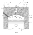
- the internal combustion engine 10 is a reciprocating type internal combustion engine in which pistons 23 reciprocate.
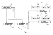
- the internal combustion engine 10 includes an internal combustion engine main body 11, an ignition device 12, an electromagnetic wave emission device 13, and a control device 35. In the internal combustion engine 10, a combustion cycle in which an air fuel mixture is ignited and combusted by the ignition device 12 is repeatedly carried out.
- the internal combustion engine main body 11 includes a cylinder block 21, a cylinder head 22, and the pistons 23.
- the cylinder block 21 is formed with a plurality of cylinders 24 each having a circular cross section. Inside of each cylinder 24, the piston 23 is reciprocatably mounted.
- the piston 23 is connected to a crankshaft (not shown) via a connecting rod (not shown).
- the crankshaft is rotatably supported by the cylinder block 21. While the piston 23 reciprocates in each cylinder 24 in an axial direction of the cylinder 24, the connecting rod converts the reciprocal movement of the piston 23 to rotational movement of the crankshaft.
- the cylinder head 22 is placed on the cylinder block 21, and a gasket 18 intervenes between the cylinder block 21 and the cylinder head 22.
- the cylinder head 22 constitutes a partitioning member that partitions a combustion chamber 20 having a circular cross section, along with the cylinder 24, the piston 23, and the gasket 18.
- a diameter of the combustion chamber 20 is, for example, approximately equal to a half wavelength of a microwave emitted to the combustion chamber 20 by the electromagnetic wave emission device 13.
- the cylinder head 22 is provided with one ignition plug 40 that constitutes a part of the ignition device 12 for each cylinder 24. As shown in Fig. 2 , a tip end part of the ignition plug 40 is exposed toward the combustion chamber 20 and locates at a central part of a ceiling surface 51 of the combustion chamber 20. The ceiling surface 51 is a surface of the cylinder head 22 and exposed toward the combustion chamber 20. An outer periphery of the tip end part of the ignition plug 40 is circular viewed from an axial direction of the ignition plug 40.
- the ignition plug 40 is provided with a central electrode 40a and a ground electrode 40b at the tip end part of the ignition plug 40. A discharge gap is formed between a tip end of the central electrode 40a and a tip end of the ground electrode 40b.
- the cylinder head 22 is formed with intake ports 25 and exhaust ports 26 for each cylinder 24.
- Each intake port 25 is provided with an intake valve 27 for opening and closing an intake side opening 25a of the intake port 25, and an injector 29 for injecting a fuel.
- each exhaust port 26 is provided with an exhaust valve 28 for opening and closing an exhaust side opening 26a of the exhaust port 26.
- each ignition device 12 is provided for each combustion chamber 20. As shown in Fig. 3 , each ignition device 12 includes an ignition coil 14 that outputs a high voltage pulse, and the ignition plug 40 which the high voltage pulse outputted from the ignition coil 14 is supplied to.
- the ignition coil 14 is connected to a direct current power supply (not shown).
- the ignition coil 14 upon receiving an ignition signal from the control device 35, boosts a voltage applied from the direct current power supply, and outputs the boosted high voltage pulse to the central electrode 40a of the ignition plug 40.
- the ignition plug 40 when the high voltage pulse is applied to the central electrode 40a, causes an insulation breakdown and a spark discharge to occur at the discharge gap. Along a discharge path of the spark discharge, discharge plasma is generated.
- the central electrode 40a is applied with a negative voltage as the high voltage pulse.
- the ignition device 12 may include a plasma enlarging part that enlarges the discharge plasma by supplying the discharge plasma with electric energy.
- the plasma enlarging part enlarges the spark discharge, for example, by supplying the spark discharge with energy of a high frequency such as a microwave.
- the electromagnetic wave emission device 13 may be utilized as the plasma enlarging part.
- the electromagnetic wave emission device 13 includes an electromagnetic wave generation device 31, an electromagnetic wave switch 32, and plugs for high frequency emission 34.
- One electromagnetic wave generation device 31 and one electromagnetic wave switch 32 are provided for the electromagnetic wave emission device 13, and the plug for high frequency emission 34 is provided for each combustion chamber 20.
- the electromagnetic wave generation device 31 upon receiving an electromagnetic wave drive signal (a pulse signal) from the control device 35, continuously outputs a microwave during a period of time of the pulse width of the electromagnetic wave drive signal.
- a semiconductor oscillator generates the microwave.
- any other oscillator such as a magnetron may be employed.
- the electromagnetic wave switch 32 includes an input terminal and a plurality of output terminals provided for the respective plugs for high frequency emission 34.
- the input terminal is electrically connected to the electromagnetic wave generation device 31.
- Each output terminal is electrically connected to an input terminal of the corresponding plug for high frequency emission 34.
- the electromagnetic wave switch 32 sequentially switches a supply destination of the microwave outputted from the electromagnetic wave generation device 31 from among the plurality of the plugs for high frequency emission 34 under a control of the control device 35.
- the plug for high frequency emission 34 is formed in a substantially column-like shape as a whole.
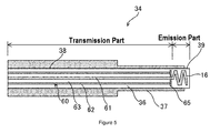
- the plug for high frequency emission 34 includes a ceramic structure 36 which is provided with a ceramic 63 (an electrical insulator) embedded with conductors, and a casing 37 that accommodates the ceramic structure 36.
- the ceramic structure 36 is formed in a column-like shape.
- the ceramic structure 36 includes a transmission part 38 provided with a transmission line 60 of the microwave, and an emission part 39 provided with an emission antenna 16.
- the transmission part 38 and the emission part 39 are integrated with each other.
- the transmission part 38 occupies most of the ceramic structure 36.
- One end part of the ceramic structure 36 constitutes the emission part 39, and the rest constitutes the transmission part 38.
- a central conductor 61 and an outer conductor 62 that constitute the transmission line 60 of the microwave are embedded in the ceramic 63.
- the central conductor 61 is a linear conductor.
- the central conductor 61 is provided on an axial center of the ceramic structure 36 over an entire length of the transmission part 38.
- the outer conductor 62 is a conductor in a shape of a rectangular cylinder, for example.
- the outer conductor 62 surrounds the central conductor 61.
- the ceramic 63 is sandwiched between the outer conductor 62 and the central conductor 61.
- the outer conductor 62 is spaced apart at a constant distance from the central conductor 61 over an entire length of the outer conductor 62.
- one end of the transmission part 38 constitutes an input terminal of the microwave.
- the transmission part 38 transmits to the emission part 39 the microwave inputted from the input terminal while preventing the microwave from leaking to the outside of the outer conductor 62.
- the outer conductor 62 may be configured by combining a conductor layer and cylindrical conductors (via holes).
- the outer conductor 62 is configured to have adjacent cylindrical conductors spaced apart at such a distance in a transmission direction of the microwave that the microwave should not leak to the outside of the outer conductor 62.
- the emission antenna 16 is embedded in the ceramic 63 so as not to expose to the outer face of the ceramic structure 36. This means that an entire surface of the emission antenna 16 is covered by the ceramic 63.
- the emission antenna 16 is a conductor formed in a helical shape.
- the emission antenna 16 is integrated at an input end thereof with the central conductor 61 of the transmission part 38.
- the casing 37 is formed in a substantially cylindrical shape. An inner diameter of the casing 37 is uniform along an axial direction of the casing 37. The inner diameter of the casing 37 is approximately the same as an outer diameter of the ceramic structure 36.
- the ceramic structure 36 is fitted into the casing 37 in such a manner that an end surface of the emission part 39 is exposed from one end of the casing 37 and an end surface of the transmission part 38 is exposed from the other end of the casing 37.
- a part of the emission part 39 is protruded from the one end of the casing 37 in such a manner that a part of the emission antenna 16 locates outside of the casing 37.
- An outer diameter of the casing 37 changes at one location in the axial direction of the casing 37.
- An outer peripheral surface of the casing 37 is formed with a step only at the one location.
- the casing 37 is smaller in the outer diameter on a distal end side from which the emission part 39 is exposed than on a base end side from which the transmission part 38 is exposed.
- the plug for high frequency emission 34 is attached to the cylinder head 22 in such a manner that the emission part 39 is exposed toward the combustion chamber 20.
- the plug for high frequency emission 34 is threaded into a fixing hole of the cylinder head 22.
- the plug for high frequency emission 34 is connected at an input terminal of the transmission part 38 to the output terminal of the electromagnetic wave switch 32 via a coaxial cable (not shown).
- the microwave when the microwave is inputted from the input terminal of the transmission part 38, the microwave passes through the inside of the outer conductor 62 of the transmission part 38.
- the microwave that has passed through the transmission part 38 is emitted from the emission antenna 16 to the combustion chamber 20.
- the outer conductor 62 is provided in the casing 37 in a non-contact manner.
- the outer conductor 62 is not electrically conducted via the casing 37, which is made of metal, to the cylinder head 22, which the plug for high frequency emission 34 is attached to. Accordingly, even though a spark current or the like flows through the cylinder head 22, the spark current or the like will not transmit via the casing 37 to the outer conductor 62.
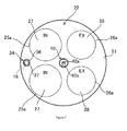
- the partitioning member that partitions the combustion chamber 20 is provided with a plurality of receiving antennae 52 that resonate with the microwave emitted from the emission antenna 16 to the combustion chamber 20.
- Each receiving antenna 52 is formed in a ring-like shape. As shown in Fig. 1 , two receiving antennae 52 are provided on a top part of the piston 23.
- Each receiving antenna 52 is electrically insulated from the piston 23 via an insulation layer 56 formed on a top surface of the piston 23, and is provided in an electrically floating state.
- the control device 35 performs a first operation of instructing the ignition device 12 to ignite the air fuel mixture and a second operation of instructing the electromagnetic wave emission device 13 to emit the microwave after the ignition of the air fuel mixture, for each combustion chamber 20 during one combustion cycle.
- control device 35 performs the first operation at an ignition timing at which the piston 23 locates immediately before the compression top dead center.
- the control device 35 outputs the ignition signal as the first operation.
- the ignition device 12 upon receiving the ignition signal, causes the spark discharge to occur at the discharge gap of the ignition plug 40, as described above.
- the air fuel mixture is ignited by the spark discharge.
- the flame spreads from an ignition location of the air fuel mixture at a central part of the combustion chamber 20 toward a wall surface of the cylinder 24.
- the control device 35 performs the second operation after the ignition of the air fuel mixture, for example, at a start timing of a latter half period of flame propagation.
- the control device 35 outputs the electromagnetic wave drive signal as the second operation.
- the electromagnetic wave emission device 13 upon receiving the electromagnetic wave drive signal, causes the emission antenna 16 to emit a continuous wave (CW) of the microwave, as described above.
- the microwave is emitted during the latter half period of the flame propagation.
- An output timing and a pulse width of the electromagnetic wave drive signal are configured such that the microwave is emitted over a period in which the flame passes through a region where the two receiving antennae 52 are provided.
- the microwave resonates with each receiving antenna 52.
- a strong electric field region having an electric field relatively strong in intensity in the combustion chamber 20 is formed over the latter half period of the flame propagation.
- the flame while passing through the strong electric field region, receives energy of the microwave and accelerates its propagation speed.
- microwave plasma is generated in the strong electric field region.
- active species such as OH radicals are generated.
- the propagation speed of the flame increases as the flame passes through the strong electric field region owing to the active species.
- the outer conductor 62 of the transmission line 60 since the outer conductor 62 of the transmission line 60 does not contact with the casing 37, the outer conductor 62 is not electrically conducted via the casing 37 to the cylinder head 22 attached with the plug for high frequency emission 34. Accordingly, even if an electric current flows through the cylinder head 22, the electric current does not transmit via the casing 37 to the outer conductor 62. Therefore, it is possible to suppress a noise in the microwave emitted from the emission antenna 16 resulted from the electric current flowing through the cylinder head 22.
- a plate-like conductor 65 is embedded between the emission antenna 16 and the outer conductor 62 in the ceramic structure 36.
- the plate-like conductor 65 is wider in area than an end surface on a side of the emission antenna 16 of the outer conductor 62, and is adapted to improve emission efficiency of the microwave from the emission antenna 16.
- the plate-like conductor 65 is formed in a shape of a ring or a letter C, and is embedded in the ceramic 63 spaced apart from and surrounding the central conductor 61.
- the plate-like conductor 65 is held in non-contact with the central conductor 61.
- the plate-like conductor 65 is provided along a cross sectional direction of the ceramic structure 36.
- the plate-like conductor 65 abuts with the outer conductor 62 alone from among the outer conductor 62 and the casing 37 so that the outer conductor 62 is not electrically connected with the casing 37.
- the plate-like conductor 65 abuts with the end surface on the side of the emission antenna 16 of the outer conductor 62.
- the plate-like conductor 65 is electrically connected to the outer conductor 62.
- the plate-like conductor 65 may abut with the casing 37 alone from among the outer conductor 62 and the casing 37. Furthermore, the plate-like conductor 65 may be held in non-contact with both the outer conductor 62 and the casing 37.
- the embodiment described above may also be configured as follows.
- the central conductor 61 is integral with the emission antenna 16. However, the central conductor 61 may be capacitively coupled with the emission antenna 16.
- the internal combustion engine main body 11 may be provided with a plurality of the plugs for high frequency emission 34.
- the present invention is useful in relation to a plug for high frequency emission provided at one end of a casing thereof with an emission antenna.
Landscapes
- Engineering & Computer Science (AREA)
- Physics & Mathematics (AREA)
- Plasma & Fusion (AREA)
- Electromagnetism (AREA)
- Optics & Photonics (AREA)
- Chemical & Material Sciences (AREA)
- Combustion & Propulsion (AREA)
- Mechanical Engineering (AREA)
- General Engineering & Computer Science (AREA)
- Spectroscopy & Molecular Physics (AREA)
- Ignition Installations For Internal Combustion Engines (AREA)
Applications Claiming Priority (2)
| Application Number | Priority Date | Filing Date | Title |
|---|---|---|---|
| JP2011197761 | 2011-09-11 | ||
| PCT/JP2012/073104 WO2013035880A1 (fr) | 2011-09-11 | 2012-09-10 | Obturateur de rayonnement haute fréquence |
Publications (2)
| Publication Number | Publication Date |
|---|---|
| EP2754884A1 true EP2754884A1 (fr) | 2014-07-16 |
| EP2754884A4 EP2754884A4 (fr) | 2016-06-15 |
Family
ID=47832314
Family Applications (1)
| Application Number | Title | Priority Date | Filing Date |
|---|---|---|---|
| EP12829239.8A Withdrawn EP2754884A4 (fr) | 2011-09-11 | 2012-09-10 | Obturateur de rayonnement haute fréquence |
Country Status (4)
| Country | Link |
|---|---|
| US (1) | US10056736B2 (fr) |
| EP (1) | EP2754884A4 (fr) |
| JP (1) | JP6082880B2 (fr) |
| WO (1) | WO2013035880A1 (fr) |
Cited By (1)
| Publication number | Priority date | Publication date | Assignee | Title |
|---|---|---|---|---|
| EP3181891A4 (fr) * | 2014-08-12 | 2017-11-08 | Imagineering, Inc. | Dispositif d'allumage |
Families Citing this family (6)
| Publication number | Priority date | Publication date | Assignee | Title |
|---|---|---|---|---|
| EP3225832A4 (fr) * | 2014-11-24 | 2017-12-13 | Imagineering, Inc. | Unité d'allumage, système d'allumage, et moteur à combustion interne |
| CN109162852A (zh) * | 2018-10-26 | 2019-01-08 | 大连民族大学 | 具有多阳极结构的双放电模式等离子体点火器 |
| CN109340014A (zh) * | 2018-10-26 | 2019-02-15 | 大连民族大学 | 一种具有单燃料进口的双放电模式等离子体点火器工作方法 |
| CN109340016A (zh) * | 2018-10-26 | 2019-02-15 | 大连民族大学 | 一种具有双进气及偏心双阳极结构的等离子体点火器 |
| CN109162853A (zh) * | 2018-10-26 | 2019-01-08 | 大连民族大学 | 一种双放电模式等离子体点火器 |
| CN109162854B (zh) * | 2018-10-26 | 2021-05-04 | 大连民族大学 | 一种双放电模式等离子体点火器的控制方法 |
Family Cites Families (22)
| Publication number | Priority date | Publication date | Assignee | Title |
|---|---|---|---|---|
| US2372429A (en) * | 1942-10-31 | 1945-03-27 | Rca Corp | Spark plug |
| US3939816A (en) * | 1974-07-12 | 1976-02-24 | The United States Of America As Represented By The National Aeronautics And Space Administration Office Of General Counsel-Code Gp | Gas filled coaxial accelerator with compression coil |
| JPS53118637A (en) * | 1977-03-24 | 1978-10-17 | Toyota Motor Corp | Ignition plug for inhibiting generation of electric wave noises |
| JPS58213120A (ja) | 1982-06-04 | 1983-12-12 | Hitachi Ltd | グロ−プラグ |
| US4774914A (en) * | 1985-09-24 | 1988-10-04 | Combustion Electromagnetics, Inc. | Electromagnetic ignition--an ignition system producing a large size and intense capacitive and inductive spark with an intense electromagnetic field feeding the spark |
| US5076223A (en) * | 1990-03-30 | 1991-12-31 | Board Of Regents, The University Of Texas System | Miniature railgun engine ignitor |
| JP3686736B2 (ja) | 1996-08-30 | 2005-08-24 | 京セラ株式会社 | 誘電体導波管線路および配線基板 |
| GB9620318D0 (en) * | 1996-09-30 | 1996-11-13 | Bebich Matthew | New ignition system and related engine components |
| US6414419B1 (en) * | 1999-12-29 | 2002-07-02 | Sei Y. Kim | Ignition spark plug |
| TWI343673B (en) * | 2006-09-11 | 2011-06-11 | Hon Hai Prec Ind Co Ltd | Complex antenna |
| CA2828176C (fr) * | 2006-09-20 | 2017-02-21 | Imagineering, Inc. | Equipement au plasma et appareil de degradation de gaz d'echappement |
| EP2178181B1 (fr) * | 2007-07-12 | 2017-08-30 | Imagineering, Inc. | Bougie d'allumage et dispositif d'analyse |
| US8887683B2 (en) * | 2008-01-31 | 2014-11-18 | Plasma Igniter LLC | Compact electromagnetic plasma ignition device |
| JP5113106B2 (ja) * | 2008-03-07 | 2013-01-09 | 日本特殊陶業株式会社 | プラズマジェット点火プラグの製造方法 |
| JP5152653B2 (ja) * | 2008-05-20 | 2013-02-27 | 株式会社エーイーティー | 火花放電点火方式とマイクロ波プラズマ点火方式を併用する点火装置 |
| JP2010096109A (ja) * | 2008-10-17 | 2010-04-30 | Denso Corp | 点火装置 |
| JP4948515B2 (ja) * | 2008-12-26 | 2012-06-06 | 日本特殊陶業株式会社 | プラズマジェット点火プラグ |
| JP2011034953A (ja) * | 2009-02-26 | 2011-02-17 | Ngk Insulators Ltd | プラズマイグナイター及び内燃機関の点火装置 |
| JP5423417B2 (ja) * | 2010-01-20 | 2014-02-19 | 株式会社デンソー | 高周波プラズマ点火装置 |
| JP2013231355A (ja) * | 2010-03-26 | 2013-11-14 | Hiromitsu Ando | 着火制御装置 |
| JP5533623B2 (ja) | 2010-12-16 | 2014-06-25 | 株式会社デンソー | 高周波プラズマ点火装置 |
| JP5422007B2 (ja) * | 2011-02-16 | 2014-02-19 | 日本特殊陶業株式会社 | プラズマジェット点火プラグ及び点火システム |
-
2012
- 2012-09-10 WO PCT/JP2012/073104 patent/WO2013035880A1/fr active Application Filing
- 2012-09-10 EP EP12829239.8A patent/EP2754884A4/fr not_active Withdrawn
- 2012-09-10 JP JP2013532690A patent/JP6082880B2/ja not_active Expired - Fee Related
- 2012-09-10 US US14/343,471 patent/US10056736B2/en active Active
Cited By (1)
| Publication number | Priority date | Publication date | Assignee | Title |
|---|---|---|---|---|
| EP3181891A4 (fr) * | 2014-08-12 | 2017-11-08 | Imagineering, Inc. | Dispositif d'allumage |
Also Published As
| Publication number | Publication date |
|---|---|
| US10056736B2 (en) | 2018-08-21 |
| JPWO2013035880A1 (ja) | 2015-03-23 |
| EP2754884A4 (fr) | 2016-06-15 |
| US20140232264A1 (en) | 2014-08-21 |
| WO2013035880A1 (fr) | 2013-03-14 |
| JP6082880B2 (ja) | 2017-02-22 |
Similar Documents
| Publication | Publication Date | Title |
|---|---|---|
| US10056736B2 (en) | High-frequency radiation plug | |
| US9538631B2 (en) | Antenna structure and internal combustion engine | |
| EP2743495A1 (fr) | Moteur à combustion interne | |
| EP2672086A2 (fr) | Moteur à combustion interne | |
| US9867270B2 (en) | Electromagnetic wave emission device | |
| US9599089B2 (en) | Internal combustion engine and plasma generation provision | |
| EP2730775A1 (fr) | Moteur à combustion interne à allumage par étincelle | |
| US10077754B2 (en) | Ignition plug and internal-combustion engine | |
| US10036364B2 (en) | Internal combustion engine | |
| US10151291B2 (en) | Internal combustion engine | |
| JP6145759B2 (ja) | アンテナ構造、高周波放射用プラグ、及び内燃機関 | |
| JP5994062B2 (ja) | アンテナ構造体、高周波放射用プラグ、内燃機関 | |
| JP6145760B2 (ja) | 高周波放射用プラグ及び内燃機関 |
Legal Events
| Date | Code | Title | Description |
|---|---|---|---|
| PUAI | Public reference made under article 153(3) epc to a published international application that has entered the european phase |
Free format text: ORIGINAL CODE: 0009012 |
|
| 17P | Request for examination filed |
Effective date: 20140325 |
|
| AK | Designated contracting states |
Kind code of ref document: A1 Designated state(s): AL AT BE BG CH CY CZ DE DK EE ES FI FR GB GR HR HU IE IS IT LI LT LU LV MC MK MT NL NO PL PT RO RS SE SI SK SM TR |
|
| DAX | Request for extension of the european patent (deleted) | ||
| RA4 | Supplementary search report drawn up and despatched (corrected) |
Effective date: 20160519 |
|
| RIC1 | Information provided on ipc code assigned before grant |
Ipc: H01T 13/44 20060101ALI20160512BHEP Ipc: F02P 23/04 20060101AFI20160512BHEP Ipc: F02P 15/04 20060101ALI20160512BHEP Ipc: H01T 13/20 20060101ALI20160512BHEP Ipc: H05H 1/46 20060101ALI20160512BHEP |
|
| STAA | Information on the status of an ep patent application or granted ep patent |
Free format text: STATUS: THE APPLICATION IS DEEMED TO BE WITHDRAWN |
|
| 18D | Application deemed to be withdrawn |
Effective date: 20200603 |