EP2754839B1 - Frame or T-shaped joints and method for fitting a frame or a T-shaped connection - Google Patents
Frame or T-shaped joints and method for fitting a frame or a T-shaped connection Download PDFInfo
- Publication number
- EP2754839B1 EP2754839B1 EP13195643.5A EP13195643A EP2754839B1 EP 2754839 B1 EP2754839 B1 EP 2754839B1 EP 13195643 A EP13195643 A EP 13195643A EP 2754839 B1 EP2754839 B1 EP 2754839B1
- Authority
- EP
- European Patent Office
- Prior art keywords
- profile
- frame
- corner
- wall
- framework
- Prior art date
- Legal status (The legal status is an assumption and is not a legal conclusion. Google has not performed a legal analysis and makes no representation as to the accuracy of the status listed.)
- Active
Links
- 238000000034 method Methods 0.000 title claims description 8
- 238000007789 sealing Methods 0.000 claims description 105
- 150000001875 compounds Chemical class 0.000 claims description 11
- 239000000565 sealant Substances 0.000 claims description 9
- 239000013013 elastic material Substances 0.000 claims description 6
- 238000009434 installation Methods 0.000 description 7
- 238000005192 partition Methods 0.000 description 6
- 239000000463 material Substances 0.000 description 4
- XAGFODPZIPBFFR-UHFFFAOYSA-N aluminium Chemical compound [Al] XAGFODPZIPBFFR-UHFFFAOYSA-N 0.000 description 2
- 229910052782 aluminium Inorganic materials 0.000 description 2
- 238000005452 bending Methods 0.000 description 2
- 239000002131 composite material Substances 0.000 description 1
- 238000009413 insulation Methods 0.000 description 1
- 230000003287 optical effect Effects 0.000 description 1
- 230000003014 reinforcing effect Effects 0.000 description 1
- 239000007787 solid Substances 0.000 description 1
- 239000011343 solid material Substances 0.000 description 1
Images


Classifications
-
- E—FIXED CONSTRUCTIONS
- E06—DOORS, WINDOWS, SHUTTERS, OR ROLLER BLINDS IN GENERAL; LADDERS
- E06B—FIXED OR MOVABLE CLOSURES FOR OPENINGS IN BUILDINGS, VEHICLES, FENCES OR LIKE ENCLOSURES IN GENERAL, e.g. DOORS, WINDOWS, BLINDS, GATES
- E06B3/00—Window sashes, door leaves, or like elements for closing wall or like openings; Layout of fixed or moving closures, e.g. windows in wall or like openings; Features of rigidly-mounted outer frames relating to the mounting of wing frames
- E06B3/96—Corner joints or edge joints for windows, doors, or the like frames or wings
- E06B3/9616—Corner joints or edge joints for windows, doors, or the like frames or wings characterised by the sealing at the junction of the frame members
- E06B3/962—Mitre joints
-
- E—FIXED CONSTRUCTIONS
- E06—DOORS, WINDOWS, SHUTTERS, OR ROLLER BLINDS IN GENERAL; LADDERS
- E06B—FIXED OR MOVABLE CLOSURES FOR OPENINGS IN BUILDINGS, VEHICLES, FENCES OR LIKE ENCLOSURES IN GENERAL, e.g. DOORS, WINDOWS, BLINDS, GATES
- E06B3/00—Window sashes, door leaves, or like elements for closing wall or like openings; Layout of fixed or moving closures, e.g. windows in wall or like openings; Features of rigidly-mounted outer frames relating to the mounting of wing frames
- E06B3/96—Corner joints or edge joints for windows, doors, or the like frames or wings
- E06B3/964—Corner joints or edge joints for windows, doors, or the like frames or wings using separate connection pieces, e.g. T-connection pieces
- E06B3/968—Corner joints or edge joints for windows, doors, or the like frames or wings using separate connection pieces, e.g. T-connection pieces characterised by the way the connecting pieces are fixed in or on the frame members
- E06B3/976—Corner joints or edge joints for windows, doors, or the like frames or wings using separate connection pieces, e.g. T-connection pieces characterised by the way the connecting pieces are fixed in or on the frame members by deformation of the frame members
-
- E—FIXED CONSTRUCTIONS
- E06—DOORS, WINDOWS, SHUTTERS, OR ROLLER BLINDS IN GENERAL; LADDERS
- E06B—FIXED OR MOVABLE CLOSURES FOR OPENINGS IN BUILDINGS, VEHICLES, FENCES OR LIKE ENCLOSURES IN GENERAL, e.g. DOORS, WINDOWS, BLINDS, GATES
- E06B7/00—Special arrangements or measures in connection with doors or windows
- E06B7/16—Sealing arrangements on wings or parts co-operating with the wings
- E06B7/22—Sealing arrangements on wings or parts co-operating with the wings by means of elastic edgings, e.g. elastic rubber tubes; by means of resilient edgings, e.g. felt or plush strips, resilient metal strips
- E06B7/23—Plastic, sponge rubber, or like strips or tubes
- E06B7/2305—Plastic, sponge rubber, or like strips or tubes with an integrally formed part for fixing the edging
- E06B7/2307—Plastic, sponge rubber, or like strips or tubes with an integrally formed part for fixing the edging with a single sealing-line or -plane between the wing and the part co-operating with the wing
-
- E—FIXED CONSTRUCTIONS
- E06—DOORS, WINDOWS, SHUTTERS, OR ROLLER BLINDS IN GENERAL; LADDERS
- E06B—FIXED OR MOVABLE CLOSURES FOR OPENINGS IN BUILDINGS, VEHICLES, FENCES OR LIKE ENCLOSURES IN GENERAL, e.g. DOORS, WINDOWS, BLINDS, GATES
- E06B1/00—Border constructions of openings in walls, floors, or ceilings; Frames to be rigidly mounted in such openings
- E06B1/04—Frames for doors, windows, or the like to be fixed in openings
- E06B1/36—Frames uniquely adapted for windows
- E06B1/366—Mullions or transoms therefor
-
- E—FIXED CONSTRUCTIONS
- E06—DOORS, WINDOWS, SHUTTERS, OR ROLLER BLINDS IN GENERAL; LADDERS
- E06B—FIXED OR MOVABLE CLOSURES FOR OPENINGS IN BUILDINGS, VEHICLES, FENCES OR LIKE ENCLOSURES IN GENERAL, e.g. DOORS, WINDOWS, BLINDS, GATES
- E06B1/00—Border constructions of openings in walls, floors, or ceilings; Frames to be rigidly mounted in such openings
- E06B1/04—Frames for doors, windows, or the like to be fixed in openings
- E06B1/52—Frames specially adapted for doors
- E06B1/524—Mullions; Transoms
-
- E—FIXED CONSTRUCTIONS
- E06—DOORS, WINDOWS, SHUTTERS, OR ROLLER BLINDS IN GENERAL; LADDERS
- E06B—FIXED OR MOVABLE CLOSURES FOR OPENINGS IN BUILDINGS, VEHICLES, FENCES OR LIKE ENCLOSURES IN GENERAL, e.g. DOORS, WINDOWS, BLINDS, GATES
- E06B3/00—Window sashes, door leaves, or like elements for closing wall or like openings; Layout of fixed or moving closures, e.g. windows in wall or like openings; Features of rigidly-mounted outer frames relating to the mounting of wing frames
- E06B3/04—Wing frames not characterised by the manner of movement
- E06B3/263—Frames with special provision for insulation
- E06B2003/26349—Details of insulating strips
- E06B2003/2635—Specific form characteristics
- E06B2003/26352—Specific form characteristics hollow
-
- E—FIXED CONSTRUCTIONS
- E06—DOORS, WINDOWS, SHUTTERS, OR ROLLER BLINDS IN GENERAL; LADDERS
- E06B—FIXED OR MOVABLE CLOSURES FOR OPENINGS IN BUILDINGS, VEHICLES, FENCES OR LIKE ENCLOSURES IN GENERAL, e.g. DOORS, WINDOWS, BLINDS, GATES
- E06B3/00—Window sashes, door leaves, or like elements for closing wall or like openings; Layout of fixed or moving closures, e.g. windows in wall or like openings; Features of rigidly-mounted outer frames relating to the mounting of wing frames
- E06B3/04—Wing frames not characterised by the manner of movement
- E06B3/263—Frames with special provision for insulation
- E06B2003/26349—Details of insulating strips
- E06B2003/2635—Specific form characteristics
- E06B2003/26359—Specific form characteristics making flush mounting with neighbouring metal section members possible
-
- E—FIXED CONSTRUCTIONS
- E06—DOORS, WINDOWS, SHUTTERS, OR ROLLER BLINDS IN GENERAL; LADDERS
- E06B—FIXED OR MOVABLE CLOSURES FOR OPENINGS IN BUILDINGS, VEHICLES, FENCES OR LIKE ENCLOSURES IN GENERAL, e.g. DOORS, WINDOWS, BLINDS, GATES
- E06B3/00—Window sashes, door leaves, or like elements for closing wall or like openings; Layout of fixed or moving closures, e.g. windows in wall or like openings; Features of rigidly-mounted outer frames relating to the mounting of wing frames
- E06B3/04—Wing frames not characterised by the manner of movement
- E06B3/263—Frames with special provision for insulation
- E06B2003/26349—Details of insulating strips
- E06B2003/26387—Performing extra functions
- E06B2003/26389—Holding sealing strips or forming sealing abutments
-
- E—FIXED CONSTRUCTIONS
- E06—DOORS, WINDOWS, SHUTTERS, OR ROLLER BLINDS IN GENERAL; LADDERS
- E06B—FIXED OR MOVABLE CLOSURES FOR OPENINGS IN BUILDINGS, VEHICLES, FENCES OR LIKE ENCLOSURES IN GENERAL, e.g. DOORS, WINDOWS, BLINDS, GATES
- E06B3/00—Window sashes, door leaves, or like elements for closing wall or like openings; Layout of fixed or moving closures, e.g. windows in wall or like openings; Features of rigidly-mounted outer frames relating to the mounting of wing frames
- E06B3/04—Wing frames not characterised by the manner of movement
- E06B3/263—Frames with special provision for insulation
- E06B3/26301—Frames with special provision for insulation with prefabricated insulating strips between two metal section members
- E06B3/26303—Frames with special provision for insulation with prefabricated insulating strips between two metal section members with thin strips, e.g. defining a hollow space between the metal section members
Definitions
- the present invention relates to a frame for a solid or a door with a frame or a T-joint and a sealing profile, which is fixed with a foot to a frame profile, wherein the sealing profile is disposed in a central region of the frame profile, and a method for Mounting a frame or a T-connection.
- the EP 1 712 723 discloses a frame for a window or a door, in which a sealing profile of a solid material, ie without hollow chambers, is provided in the central region.
- the sealing profile is guided in the corner region of the frame via a corner element, which has an arcuate portion in order to avoid a strong buckling of the sealing profile.
- this guidance of the sealing profile allows an arcuate course that interferes with the closing of a window or door leaf and can be easily damaged.
- the height of the sealing profile is limited, since the window sash must be movable within the bent portion of the sealing profile.
- a frame profile is shown, in which a sealing profile is arranged in a central region of the frame and bent in the corner region.
- the bent portion is comparatively strong in the interior of the corner and therefore requires large gaps to the wing.
- the DE 24 60 417 discloses a method of forming a corner on a weather strip in which a recess is provided into which a corner piece is placed to better seal vehicle doors.
- the DE 31 33 378 shows a center seal for a frame with a protruding sealing lip.
- an improved center seal is shown, which is fixable via two Veank ceremoniessffure to a frame.
- GB 1 460 169 discloses a door seal with a hollow chamber, in which a reinforcing element is inserted in order to improve in the corner region To maintain dimensional stability. Also in the US 3,023,466 a sealing profile is shown, which is bent in the corner area and is fixed by an insert.
- the sealing profile is cut in a corner region of the frame or the T-connection on the outside and aligned at an angle.
- the sealing profile can be bent in a much smaller radius, so that in the corner region protrusion of the sealing profile is avoided by a weakly rounded portion.
- the sealing profile can be aligned in exact position over the incision in the corner area and strong material stresses in the bending area can be avoided.
- a corner element is arranged on the incision of the sealing profile.
- the corner member may serve to align the angularly oriented sealing profile and allow prefixing of the sealing profile in the aligned position.
- the sealing profile is preferably formed as a hollow chamber profile, in particular of an elastic material.
- the hollow chambers can occupy at least 40%, in particular at least 50% of the volume of the sealing profile.
- the sealing profile preferably has an outer wall with the foot part and an inner wall, on which a sealing projection is formed, wherein the outer wall and the inner wall are connected to each other via a plurality of intermediate walls.
- the inner wall and the outer wall as well as the intermediate walls are each gulled on their surfaces, so that a cutting over a part of the intermediate walls is possible without further damaging the sealing profile.
- an incision can be made, which runs through an outer wall and at least partially through a region of the intermediate walls, preferably the intermediate walls are complete severed, so that a simple bending of the sealing profile is made possible in the corner.
- the corner element has at least one channel for distributing sealing compound.
- the channel may then have one or more distribution sections to seal the areas where two frame profiles abut each other, such as the miter surface of two frame profiles or the abutment surface.
- the corner element is at least partially made of an elastic material and can be latched to webs of the frame profile.
- the corner element can be latched to two adjacent frame profiles in the corner area, so that it is held exactly in the corner area.
- the corner element may have projections which can be inserted into hollow chambers of the sealing profile.
- the sealing profile can also be preassembled outside the frame profiles on the corner element and then fixed together with the corner element in the corner region.
- the corner element may in this case essentially have a cuboid web on which the projections for fixing the sealing profile are formed, wherein in the cuboid web at least one channel for distributing sealing compound is formed, which is perpendicular to the plane of a filling element in the frame or the T. Connection extends.
- the sealing profile is provided circumferentially on a frame.
- the two front ends of the sealing profile abut each other in abutment, which still leads to sufficient sealing properties.
- four corner elements may be provided on a frame, by means of which an integral sealing profile is aligned.
- a sealing profile is first cut on an outer wall and then on kinked the cut portion to align it at an angle.
- a corner member is then inserted into the cut portion to mount the seal profile to a frame profile of the frame or a T-joint.
- the sealing profile can be formed continuously in the corner without the sealing profile protruding too far into the interior.
- a sealant can then be injected into a channel in the corner element in order to seal the corner area in an optimized manner.
- a frame 1 comprises a first frame profile 2 and a second frame profile 3, which are aligned at an angle to each other, preferably at right angles.
- the frame profiles 2 and 3 along a miter 4 adjacent to each other.
- FIG. 1B a corner element 5 is shown on the frame profile 2 and the frame profile 3 in the corner region, which is arranged in the extension to a sealing profile 6 which is fixed both to the frame profile 2 and to the frame profile 3.
- a sealing profile 6 which is fixed both to the frame profile 2 and to the frame profile 3.
- In the corner of the sealing profile 6 is bent with a small radius.
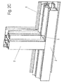
- FIG. 2A a T-joint 1 'is shown, in which a first frame profile 2' is connected to a second frame profile 3 ', wherein the frame profiles 2' and 3 'are aligned at right angles to each other.
- the frame profile 3 ' is frontally fixed to an abutment surface 4' on the frame profile 2 '.
- a corner element 5 can be mounted in the corner region of such a T-connection 1 ', by means of which a sealing profile 6 can be aligned.
- the sealing profile 6 is in Figure 2C fixed to the frame profiles 2 'and 3' and bent at right angles in the corner.
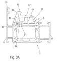
- FIG. 3A the sealing profile 6 is shown in a mounted on the frame profile 2 position.
- the frame profile 2 is constructed identical to the frame profile 3 and also the frame profiles 2 'and 3' can be designed accordingly.
- the frame profile 2 comprises an inner shell 20 made of aluminum and an outer shell 22 made of aluminum, which are connected to each other via insulating webs 21 made of plastic.
- inside and outside refer to the preferred installation situation of a window or a door with a frame profile 2, 3, 2 'or 3' and are also interchangeable with reverse installation.
- a groove 24 is formed, in which a foot portion 60 of the sealing profile 6 is inserted and is fixed on the inner directed webs of the groove 24.
- the sealing profile 6 is formed as a hollow chamber profile and has an outer wall 61 and an inner wall 62, wherein on the inner wall 62, a sealing projection 69 is integrally formed.
- the inner wall 62 is connected to the outer wall 61 via a plurality of intermediate walls.
- the terms “inside” and “outside” refer here to the corner area in which the sealing profile 6 is bent and therefore radially inner and outer regions are present.
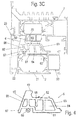
- FIG. 3B is the frame profile 2 of FIG. 3A shown together with a wing profile 7 which is movable relative to the frame profile 2.
- the wing profile is formed as a thermally insulated composite profile and has on its outer side a bearing surface 71 which cooperates with a sealing profile which is fixed in the groove 23.
- the airfoil 7 has on the inside a groove 72 on which an inner gasket is drawn, which cooperates with the inner shell 20 of the frame profile 2, so that the sealing profile 6 is formed as a central seal, which is arranged between an outer and an inner seal.
- the sealing profile 6 extends substantially over the width of the insulating webs 21st
- the sealing profile 6 rests with the sealing projection 69 on a block 70, which is part of an insulating web of the airfoil 7.
- the block 70 deforms the sealing profile 6 as shown in FIG FIG. 3C is shown.
- the sealing projection 69 abuts with a sealing surface on the block 70, wherein the sealing profile 6 in the region of the inner wall 62 to the left in FIG. 3C was moved.
- the inner wall 62 is displaceable relative to the outer wall 61 via the intermediate walls 63, 64, 65 and 66 in the manner of a parallelogram, wherein in FIG. 3C the original position of the intermediate wall 63 is shown in dashed lines and the pivoted position with 63 '.
- the sealing profile 6 is shown in detail.
- the sealing profile 6 consists of an elastic material, in particular a foamed cell or sponge rubber, which is spilled on the insides.
- the sealing profile 6 has an outer wall 61 and an inner wall 62, wherein the term “outside” and “inside” refer to a corner portion of a frame or a T-joint, on which the outer wall 61 is on the outside and the inner wall 62 is provided lying inside.
- the outer wall 61 and the inner wall 62 are connected to each other via four intermediate walls 63, 64, 65, and 66, wherein the number of intermediate walls 63, 64, 65, 66 can be varied to the number of hollow chambers in the Seal profile 6 to vary.
- a partition wall 68 is further formed, which is free-hanging and does not extend to the outer wall 61.
- a foot part 60 is further shown with a mushroom-shaped cross section and adjacent to the foot part 60, a support web 67 is provided which supports the sealing profile 6 when the sealing projection 69 is pushed into a closed position, as in FIG. 3C is shown.
- FIG. 5A the sealing profile 6 is shown in a state during assembly.
- the sealing profile 6 is cut in a corner region, wherein at least the outer wall 61 is severed, but preferably also a part of the intermediate walls 63, 64, 65 and 66, which can for example also be completely severed. Only the inner wall 62 must remain at least partially continuous, so that the sealing profile 6 can be aligned at an angle after the incision, as in FIG. 5A is shown.
- the hollow chambers are opened and in the corner region of the sealing profile 6, a corner element 5 is arranged.
- the corner element 5 is essentially formed by a cuboid web which has angled protrusions 53, 54 and 55 which can be inserted into the individual hollow chambers of the sealing profile 6. Furthermore, the corner element 5 has two plates 52 protruding at right angles, which can be fixed to a frame profile 2, 3, 2 ', 3' and also provide for the distribution of a sealing compound. Via a channel 10, a sealing compound is injected into the corner element 5 after assembly.
- the corner element 5 adapts to the cut-in end edges of the sealing profile 6 substantially form-fitting and closes them.
- An upper side 51 of the corner element 5 is aligned substantially flush with an outer side of the sealing profile 6 and the projections 53, 54 and 55 are inserted into the hollow chambers of the sealing profile 6, so that the sealing profile 6 is held pre-fixed via the corner element 5 in the angled position ,
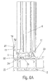
- FIG. 6A the sealing profile 6 is shown in a position mounted on the corner element 5, wherein the corner element 5 is fixed to the frame profile 2.
- the plates 52 on the corner element 5 have groove-shaped channels 13 and 14, engage in the webs of the groove 23 on the outer shell 22 of the frame profile 2.
- the corner element 5 can be fixed between the outer shell 22 and the inner shell 20, wherein for this purpose on the corner element. 5 adjacent to the top 51 a locking element 46 engages in a groove 26 on the inner shell 20.
- a latching means 56 is also provided on the corner element 5, which engages in a groove 25 on the outer shell 22.
- the latching means 46 and 56 in the corner element 5 are at least partially elastic and allow latching of the corner element 5 during assembly. It is also possible to form the corner element 5 in total of a material with a certain elasticity or to provide at least individual sections of an elastic material.
- FIG. 6C is a section through the corner element 5 is shown, wherein the channel 10 is recognizable for distributing sealing compound.
- the channel 10 is connected via one or more distribution sections to the channels 13 and 14, so that at the top 51 injected sealant is distributed over the channel 10 in the corner.
- the channel 10 opens in the region of the miter surface 4 of two frame sections 2 and 3, wherein via the channels 13 and 14, a seal in the region of an abutment surface 4 'can be prepared by the sealant.
- openings 16 are provided on the side facing the sealing profile 6 on the channel 10 in order to inject sealing compound into the hollow chambers of the sealing profile 6 and to securely seal this region.
- a further opening 18 is provided on the channel 10 in order to inject sealant in this area can.
- the corner element 5 is preferably made of plastic and can be dimensionally stable in the corner region of two frame sections 2 and 3 or 2 'and 3' fixed, for easy installation, the corner element 5 via one or more locking means 46 and 56 can be latched.
- the corner element 5 comprises at the cuboid web a plurality of web-shaped projections 53, 54 and 55, which are insertable into the hollow chambers of the sealing profile 6.
- the projections 53, 54, 55 are aligned angularly, preferably substantially at a right angle, in order to pre-fix the sealing profile 6 in an angular position can.
- the sealant is then distributed over the channel 10, wherein the channel 10 is arranged on the opposite side in the region of the plates 52 and there distributed over a first distribution section 12 sealing compound along the miter surface 4 of a frame 1.
- the first distribution section 12 is connected via two groove-shaped distribution sections 11, which transport the sealant to the groove-shaped channels 13 and 14.
- an opening 15 is formed, which is provided on the upper side of the plate 52 and allows an optical control, whether sufficient sealant was injected into the corner element 5, because with a sufficient filling of the corner element 5 sealing compound from the opening 15th out.
- locking elements 55 and 56 are further formed on opposite sides, which can be latched to a frame profile 2 at corresponding webs or grooves 26 and 25.
- a plate 57 is further provided, which tapers pointedly to the front and engages under an outer wall of the sealing profile.
- the plates 52 are arranged at a distance from the sealing profile 6.
- a recess 17 is provided, which is used as needed for injecting sealant by the bottom wall of the recess 17 is broken, so that then a nozzle can be inserted into the channel 10.
- the corner element 5 is formed in two parts and comprises a first part 58 made of a softer, elastic material and a second part 59 of a more dimensionally stable material.
- the first part 58 made of softer material allows latching of the corner element 5 on a frame profile 2, 3, 2 ', 3'.
- the first part 58 has for this purpose a sleeve 40 which can be inserted into the channel 10 on the second part 59, so that after assembly, the first part 58 and the second part 59 are firmly connected to each other.
- a sealing profile 6 is cut in the region of an outer wall 61 and preferably also in the region of the intermediate walls 63, 64, 65 and 66 and bent or folded over.
- a corner element 5 is then inserted, as shown in the Figures 5A and 5B is shown.
- the corner element 5 can optionally already on a frame 1 or a T-connection 1 ' be pre-assembled or loosely mounted on the sealing profile 6, so that then the unit of sealing profile 6 and corner element 5 can be mounted on a frame 1 or a T-connection 1 '.
- After mounting the sealing profile 6 on the frame 1 or the T-joint 1 'sealing compound is then injected into the channel 10 and distributed in the corner member 5 to the frame profiles 2, 3, 2', 3 'seal accordingly.
- the sealing profile 6 When mounting a frame, the sealing profile 6 is held over four corner elements 5, wherein the sealing profile 6 is preferably provided in one piece.
- the sealing profile 6 is in the region of the end portions with the end faces to each other to obtain a sufficient seal.
Description
Die vorliegende Erfindung betrifft einen Blendrahmen für ein Fester oder eine Tür mit einem Rahmen oder einer T-Verbindung und einem Dichtungsprofil, das mit einem Fußteil an einem Rahmenprofil festgelegt ist, wobei das Dichtungsprofil in einem mittleren Bereich des Rahmenprofils angeordnet ist, sowie ein Verfahren zur Montage eines Rahmens oder einer T-Verbindung.The present invention relates to a frame for a solid or a door with a frame or a T-joint and a sealing profile, which is fixed with a foot to a frame profile, wherein the sealing profile is disposed in a central region of the frame profile, and a method for Mounting a frame or a T-connection.
Die
Auch bei der
Die
Die
In der
Es ist daher Aufgabe der vorliegenden Erfindung, einen Blendrahmen für ein Fenster oder eine Tür sowie ein Verfahren zur Montage eines Rahmens oder einer T-Verbindung zu schaffen, die eine verbesserte Verlegung des Dichtungsprofils im Eckbereich ermöglichen und für eine hohe Wärmedämmung sorgen.It is therefore an object of the present invention to provide a window frame for a window or a door and a method for mounting a frame or a T-connection, which allow improved installation of the sealing profile in the corner and provide high thermal insulation.
Diese Aufgabe wird mit einem Blendrahmen mit den Merkmalen des Anspruches 1 sowie einem Verfahren zur Montage eines Rahmens oder einer T-Verbindung mit den Merkmalen des Anspruches 13 gelöst.This object is achieved with a frame with the features of claim 1 and a method for mounting a frame or a T-connection with the features of
Erfindungsgemäß ist das Dichtungsprofil in einem Eckbereich des Rahmens oder der T-Verbindung an der Außenseite eingeschnitten und winklig ausgerichtet. Dadurch kann das Dichtungsprofil in einem wesentlich kleineren Radius gebogen werden, so dass im Eckbereich ein Hervorstehen des Dichtungsprofils durch einen nur schwach gerundeten Abschnitt vermieden wird. Zudem kann das Dichtungsprofil über den Einschnitt im Eckbereich positionsgenau ausgerichtet werden und starke Materialbeanspruchungen im Knickbereich werden vermieden.According to the invention, the sealing profile is cut in a corner region of the frame or the T-connection on the outside and aligned at an angle. Thereby, the sealing profile can be bent in a much smaller radius, so that in the corner region protrusion of the sealing profile is avoided by a weakly rounded portion. In addition, the sealing profile can be aligned in exact position over the incision in the corner area and strong material stresses in the bending area can be avoided.
Gemäß einer bevorzugten Ausgestaltung der Erfindung ist an dem Einschnitt des Dichtungsprofils ein Eckelement angeordnet. Das Eckelement kann zur Ausrichtung des winklig ausgerichteten Dichtungsprofils dienen und eine Vorfixierung des Dichtungsprofils in der ausgerichteten Position ermöglichen.According to a preferred embodiment of the invention, a corner element is arranged on the incision of the sealing profile. The corner member may serve to align the angularly oriented sealing profile and allow prefixing of the sealing profile in the aligned position.
Das Dichtungsprofil ist vorzugsweise als Hohlkammerprofil ausgebildet, insbesondere aus einem elastischen Material. Die Hohlkammern können mindestens 40 %, insbesondere mindestens 50 % des Volumens des Dichtungsprofils einnehmen. Das Dichtungsprofil weist bevorzugt eine äußere Wand mit dem Fußteil und eine innere Wand auf, an der ein Dichtungsvorsprung ausgebildet ist, wobei die äußere Wand und die innere Wand über mehrere Zwischenwände miteinander verbunden sind. Die innere Wand und die äußere Wand sowie die Zwischenwände sind an ihren Oberflächen jeweils verhautet, so dass ein Einschneiden über einen Teil der Zwischenwände möglich ist, ohne das Dichtungsprofil weiter zu beschädigen. Dabei kann ein Einschnitt eingebracht werden, der durch eine äußere Wand und zumindest teilweise durch einen Bereich der Zwischenwände verläuft, vorzugsweise werden die Zwischenwände vollständig durchtrennt, so dass ein einfaches Umbiegen des Dichtungsprofils im Eckbereich ermöglicht wird.The sealing profile is preferably formed as a hollow chamber profile, in particular of an elastic material. The hollow chambers can occupy at least 40%, in particular at least 50% of the volume of the sealing profile. The sealing profile preferably has an outer wall with the foot part and an inner wall, on which a sealing projection is formed, wherein the outer wall and the inner wall are connected to each other via a plurality of intermediate walls. The inner wall and the outer wall as well as the intermediate walls are each gulled on their surfaces, so that a cutting over a part of the intermediate walls is possible without further damaging the sealing profile. In this case, an incision can be made, which runs through an outer wall and at least partially through a region of the intermediate walls, preferably the intermediate walls are complete severed, so that a simple bending of the sealing profile is made possible in the corner.
Vorzugsweise weist das Eckelement mindestens einen Kanal zum Verteilen von Dichtungsmasse auf. Der Kanal kann dann einen oder mehrere Verteilungsabschnitte aufweisen, um die Bereiche abzudichten, an denen zwei Rahmenprofile aneinander anliegen, beispielsweise die Gehrungsfläche zweier Rahmenprofile oder die Stoßfläche.Preferably, the corner element has at least one channel for distributing sealing compound. The channel may then have one or more distribution sections to seal the areas where two frame profiles abut each other, such as the miter surface of two frame profiles or the abutment surface.
Für eine leichte Montage ist das Eckelement zumindest teilweise aus einem elastischen Material hergestellt und kann an Stegen des Rahmenprofils verrastbar sein. Das Eckelement kann an zwei benachbarten Rahmenprofilen im Eckbereich verrastet werden, so dass es positionsgenau im Eckbereich gehalten wird.For ease of assembly, the corner element is at least partially made of an elastic material and can be latched to webs of the frame profile. The corner element can be latched to two adjacent frame profiles in the corner area, so that it is held exactly in the corner area.
Für eine gute Vorfixierung des Dichtungsprofils im Eckbereich kann das Eckelement Vorsprünge aufweisen, die in Hohlkammern des Dichtungsprofils einfügbar sind. Dadurch kann das Dichtungsprofil auch außerhalb der Rahmenprofile an dem Eckelement vormontiert und dann zusammen mit dem Eckelement im Eckbereich fixiert werden. Es ist natürlich auch möglich, das Eckelement zunächst im Eckbereich eines Rahmens oder einer T-Verbindung zu fixieren, und dann das Dichtungsprofil an dem Eckelement festzulegen, wobei die Vorsprünge eine leichte Überprüfung ermöglichen, ob das Dichtungsprofil korrekt an dem Eckelement montiert wurde.For a good prefixing of the sealing profile in the corner region, the corner element may have projections which can be inserted into hollow chambers of the sealing profile. As a result, the sealing profile can also be preassembled outside the frame profiles on the corner element and then fixed together with the corner element in the corner region. Of course, it is also possible to first fix the corner element in the corner region of a frame or a T-joint, and then fix the sealing profile to the corner element, wherein the projections allow easy checking whether the sealing profile has been correctly mounted on the corner element.
Das Eckelement kann dabei im Wesentlichen einen quaderförmigen Steg aufweisen, an dem die Vorsprünge zur Fixierung des Dichtungsprofils ausgebildet sind, wobei in dem quaderförmigen Steg mindestens ein Kanal zum Verteilen von Dichtungsmasse ausgebildet ist, der sich senkrecht zur Ebene eines Füllungselementes in dem Rahmen oder der T-Verbindung erstreckt.The corner element may in this case essentially have a cuboid web on which the projections for fixing the sealing profile are formed, wherein in the cuboid web at least one channel for distributing sealing compound is formed, which is perpendicular to the plane of a filling element in the frame or the T. Connection extends.
Für eine einfache Montage wird das Dichtungsprofil umlaufend an einem Rahmen vorgesehen. Dabei können die beiden stirnseitigen Enden des Dichtungsprofils auf Stoß aneinander anliegen, was noch zu ausreichenden Dichteigenschaften führt. Dabei können vier Eckelemente an einem Rahmen vorgesehen sein, mittels denen ein einstückiges Dichtungsprofil ausgerichtet wird.For easy installation, the sealing profile is provided circumferentially on a frame. In this case, the two front ends of the sealing profile abut each other in abutment, which still leads to sufficient sealing properties. In this case, four corner elements may be provided on a frame, by means of which an integral sealing profile is aligned.
Für die Montage eines entsprechenden Rahmens oder einer T-Verbindung wird zunächst ein Dichtungsprofil an einer Außenwand eingeschnitten und dann an dem eingeschnittenen Abschnitt geknickt, um es winklig auszurichten. In den eingeschnittenen Abschnitt wird dann ein Eckelement eingefügt, um das Dichtungsprofil an einem Rahmenprofil des Rahmens oder einer T-Verbindung zu montieren. Dadurch kann das Dichtungsprofil im Eckbereich durchgehend ausgebildet sein, ohne dass das Dichtungsprofil zu weit in den Innenbereich hervorsteht.For the installation of a corresponding frame or a T-connection, a sealing profile is first cut on an outer wall and then on kinked the cut portion to align it at an angle. A corner member is then inserted into the cut portion to mount the seal profile to a frame profile of the frame or a T-joint. Thereby, the sealing profile can be formed continuously in the corner without the sealing profile protruding too far into the interior.
Für eine einfache Montage des Eckelementes kann dieses an einem oder zwei Rahmenprofilen im Eckbereich verrastet werden. Nach der Montage des Eckelementes kann dann ein Dichtmittel in einen Kanal in dem Eckelement eingespritzt werden, um den Eckbereich optimiert abzudichten.For a simple installation of the corner element this can be locked to one or two frame profiles in the corner. After assembly of the corner element, a sealant can then be injected into a channel in the corner element in order to seal the corner area in an optimized manner.
Die Erfindung wird nachfolgend anhand mehrerer Ausführungsbeispiele mit Bezug auf die beigefügten Zeichnungen näher erläutert. Es zeigen:
- Figuren 1A und 1 B
- zwei perspektivische Ansichten eines Eckbereichs eines erfindungsgemäßen Rahmens;
- Figuren 2A bis 2C
- mehrere Ansichten eines Eckbereiches einer erfindungsgemäßen T-Verbindung;
- Figuren 3A bis 3C
- mehrere Schnittansichten durch ein Rahmenprofil mit eingezogenem Dichtungsprofil;
Figur 4- eine Schnittansicht durch das Dichtungsprofil an dem Rahmenprofil;
- Figuren 5A und 5B
- zwei Ansichten bei der Montage eines Eckelementes an dem Dichtungsprofil;
- Figuren 6A bis 6C
- mehrere Schnittansichten durch ein Rahmenprofil im Bereich eines Eckelementes;
- Figuren 7A bis 7I
- mehrere Ansichten eines Eckelementes für einen Rahmen oder eine T-Verbindung, und
- Figuren 8A bis 8C
- mehrere Ansichten des Eckelementes der
Figur 7 in Explosionsdarstellungen.
- FIGS. 1A and 1B
- two perspective views of a corner region of a frame according to the invention;
- FIGS. 2A to 2C
- several views of a corner region of a T-junction according to the invention;
- FIGS. 3A to 3C
- several sectional views through a frame profile with retracted sealing profile;
- FIG. 4
- a sectional view through the sealing profile on the frame profile;
- FIGS. 5A and 5B
- two views in the assembly of a corner element on the sealing profile;
- FIGS. 6A to 6C
- several sectional views through a frame profile in the region of a corner element;
- FIGS. 7A to 7I
- several views of a corner element for a frame or a T-connection, and
- FIGS. 8A to 8C
- several views of the corner element of
FIG. 7 in exploded views.
Ein Rahmen 1 umfasst ein erstes Rahmenprofil 2 und ein zweites Rahmenprofil 3, die winklig zueinander ausgerichtet sind, vorzugsweise rechtwinklig. Hierfür sind die Rahmenprofile 2 und 3 entlang einer Gehrungsfläche 4 aneinander anliegend.A frame 1 comprises a
In
In
In
An dem Isoliersteg 21 ist eine Nut 24 ausgebildet, in die ein Fußteil 60 des Dichtungsprofils 6 eingefügt ist und über die nach inneren gerichteten Stege der Nut 24 fixiert wird.At the insulating
Das Dichtungsprofil 6 ist als Hohlkammerprofil ausgebildet und weist eine äußere Wand 61 und eine innere Wand 62 auf, wobei an der inneren Wand 62 ein Dichtungsvorsprung 69 angeformt ist. Die innere Wand 62 ist mit der äußeren Wand 61 über mehrere Zwischenwände miteinander verbunden. Die Begriffe "innen" und "außen" beziehen sich hier auf den Eckbereich, in dem das Dichtungsprofil 6 umgebogen wird und daher radial innere und äußere Bereiche vorhanden sind.The sealing
In
Das Dichtungsprofil 6 liegt mit dem Dichtvorsprung 69 an einem Block 70 an, der Teil eines Isoliersteges des Flügelprofils 7 ist. In der geschlossenen Position verformt der Block 70 das Dichtungsprofil 6, wie dies in
In
Die äußere Wand 61 und die innere Wand 62 sind über vier Zwischenwände 63, 64, 65, und 66 miteinander verbunden, wobei die Anzahl der Zwischenwände 63, 64, 65, 66 variiert werden kann, um die Anzahl der Hohlkammern in dem Dichtungsprofil 6 zu variieren. An der äußeren Wand 62 ist ferner eine Trennwand 68 ausgebildet, die freihängend ausgebildet ist und sich nicht bis zu der äußeren Wand 61 erstreckt. An der äußeren Wand 61 ist ferner noch ein Fußteil 60 mit einem pilzkopfförmigen Querschnitt gezeigt und benachbart zu dem Fußteil 60 ist ein Stützsteg 67 vorgesehen, der das Dichtungsprofil 6 unterstützt, wenn der Dichtungsvorsprung 69 in eine geschlossene Position geschoben wird, wie dies in
In
Wie in
In
An der Oberseite 51 stehen seitlich Stege 49 hervor, die das Dichtungsprofil 6 in der am Eckelement 5 montierten Position übergreifen. Das Dichtungsprofil 6 ist dann zwischen den Stegen 49 an der Oberseite 51 und einer am Eckelement 5 angeordneten Platte 57 klemmend fixiert.On the
In
Das Eckelement 5 besteht dabei vorzugsweise aus Kunststoff und kann formstabil in dem Eckbereich zweier Rahmenprofile 2 und 3 bzw. 2' und 3' fixiert werden, wobei für eine einfache Montage das Eckelement 5 über ein oder mehrere Rastmittel 46 und 56 verrastbar ist.The
In den
An dem Eckelement 5 sind ferner an gegenüberliegenden Seiten Rastelemente 55 und 56 ausgebildet, die an einem Rahmenprofil 2 an entsprechenden Stegen oder Nuten 26 und 25 verrastet werden können. In einem mittleren Bereich des Eckelementes 5 ist ferner eine Platte 57 vorgesehen, die spitz nach vorne zuläuft und eine Außenwand des Dichtungsprofils untergreift. Dadurch sind die Platten 52 beabstandet von den Dichtungsprofil 6 angeordnet. Zwischen den Platten 52 und der Platte 57 ist eine Aussparung 17 vorgesehen, die bei Bedarf zum Injizieren von Dichtmasse eingesetzt wird, indem die Bodenwand der Aussparung 17 durchbrochen wird, so dass dann eine Düse in den Kanal 10 eingefügt werden kann.On the
Wie in den
Für die Montage eines Rahmens oder einer T-Verbindung wird ein Dichtungsprofil 6 im Bereich einer äußeren Wand 61 und vorzugsweise auch im Bereich der Zwischenwände 63, 64, 65 und 66 eingeschnitten und umgebogen bzw. umgeknickt. In dem eingeschnittenen Abschnitt wird dann ein Eckelement 5 eingefügt, wie dies in den
Bei der Montage eines Rahmens wird das Dichtungsprofil 6 über vier Eckelemente 5 gehalten, wobei das Dichtungsprofil 6 vorzugsweise einstückig vorgesehen wird. Das Dichtungsprofil 6 liegt im Bereich der Endabschnitte mit den Stirnseiten aneinander an, um eine ausreichende Abdichtung zu erhalten. Optional ist es auch möglich, ein Verbindungselement an den Endabschnitten des Dichtungsprofils 6 vorzusehen.When mounting a frame, the sealing
- 11
- Rahmenframe
- 1'1'
- T-VerbindungT-connection
- 2, 2', 3, 3'2, 2 ', 3, 3'
- Rahmenprofilframe profile
- 44
- Gehrungsflächemiter
- 4'4 '
- Stoßflächeabutting face
- 55
- EckelementCorner
- 66
- Dichtungsprofilweatherstrip
- 77
- Flügelprofilairfoil
- 1010
- Kanalchannel
- 1111
- Verteilungsabschnittdistribution section
- 1212
- Verteilungsabschnittdistribution section
- 1313
- Kanalchannel
- 1414
- Kanalchannel
- 1515
- Öffnungopening
- 1616
- Öffnungopening
- 1717
- Aussparungrecess
- 1818
- Öffnungopening
- 2020
- Innenschaleinner shell
- 2121
- IsolierstegInsulating web
- 2222
- Außenschaleouter shell
- 2323
- Nutgroove
- 2424
- Nutgroove
- 2525
- Nutgroove
- 2626
- Nutgroove
- 4040
- Hülseshell
- 4646
- Rastmittellatching means
- 4949
- StegeStege
- 5151
- Oberseitetop
- 5252
- Plattenplates
- 5353
- Vorsprunghead Start
- 5454
- Vorsprunghead Start
- 5555
- Vorsprunghead Start
- 5656
- Rastmittellatching means
- 5757
- Platteplate
- 5858
- erstes Teilfirst part
- 5959
- zweites Teilsecond part
- 6060
- Fußteilfootboard
- 6161
- äußere Wandouter wall
- 6262
- innere Wandinner wall
- 63, 63'63, 63 '
- Zwischenwandpartition
- 6464
- Zwischenwandpartition
- 6565
- Zwischenwandpartition
- 6666
- Zwischenwandpartition
- 6767
- Stützstegsupporting web
- 6868
- Trennwandpartition wall
- 6969
- Dichtungsvorsprungsealing projection
- 7070
- Blockblock
- 7171
- Anlageflächecontact surface
- 7272
- Nutgroove
Claims (15)
- A frame for a window or a door having a framework (1) or a T-connection (1') and a seal profile (6) which is fixed with a base part (60) on a framework profile (2, 2', 3, 3'), wherein the seal profile (6) is arranged in a middle region of the framework profile (2, 2', 3, 3'), characterized in that the seal profile (6) is notched on the outer side and aligned at an angle in a corner region of the framework (1) or the T-connection (1').
- The frame according to Claim 1, characterized in that a corner element (5) is arranged on the notch of the seal profile (6).
- The frame according to Claim 1 or 2, characterized in that the seal profile (6) is designed as a hollow chamber profile.
- The frame according to any one of the preceding claims, characterized in that the seal profile (6) has an outer wall (61) having the base part (60) and an inner wall (62), on which a seal projection (69) is formed, and the outer wall (61) and the inner wall (62) are connected to one another via multiple intermediate walls (63, 64, 65, 66).
- The frame according to any one of the preceding claims, characterized in that the seal profile (6) has an outer wall (61) and an inner wall (62), which are connected to one another via intermediate walls (63, 64, 65, 66), and a notch is provided on the seal profile (6), which extends through the outer wall (61) and at least through a region of the intermediate walls (63, 64, 65, 66).
- The frame according to any one of the preceding claims, characterized in that at least one channel (10) for distributing sealing compound is formed on the corner element (5).
- The frame according to any one of the preceding claims, characterized in that the corner element (5) is produced at least partially from an elastic material and can be latched onto webs (25, 26) of a framework profile (2, 2', 3, 3').
- The frame according to any one of the preceding claims, characterized in that the corner element (5) has projections (53, 54, 55), which are insertable into hollow chambers of the seal profile (6).
- The frame according to any one of the preceding claims, characterized in that the seal profile (6) is provided peripherally on the framework (1).
- The frame according to Claim 9, characterized in that the two frontal ends of the seal profile (6) abut one another.
- The frame according to Claim 9 or 10, characterized in that four corner elements (5) are provided on the framework (1), by means of which a one-piece seal profile (6) is aligned.
- The frame according to any one of the preceding claims, characterized in that the frame (1) has a first framework profile (2) and a second framework profile (3) which are aligned perpendicularly to one another.
- A method for mounting a framework (1) or a T-connection (1'), in particular a frame for a window or a door, having the following steps:- notching a seal profile (6), which is provided with at least one hollow chamber, on an outer wall (61);- buckling the seal profile (6) at the notched section;- inserting a corner element (5) at the notched section, and- mounting the seal profile (6) on a framework profile (2, 2', 3, 3') to produce a framework (1) or a T-connection (1').
- The method according to Claim 13, characterized in that the corner element (5) is latched on one or two framework profiles (2, 2', 3, 3') in the corner region.
- The method according to Claim 13 or 14, characterized in that, after the mounting of the corner element (5), a sealant is injected into a channel (10) in the corner element (5).
Applications Claiming Priority (1)
| Application Number | Priority Date | Filing Date | Title |
|---|---|---|---|
| DE102013100240.4A DE102013100240A1 (en) | 2013-01-11 | 2013-01-11 | Frame or T-joint and method for mounting a frame or T-joint |
Publications (2)
| Publication Number | Publication Date |
|---|---|
| EP2754839A1 EP2754839A1 (en) | 2014-07-16 |
| EP2754839B1 true EP2754839B1 (en) | 2016-07-13 |
Family
ID=49759038
Family Applications (1)
| Application Number | Title | Priority Date | Filing Date |
|---|---|---|---|
| EP13195643.5A Active EP2754839B1 (en) | 2013-01-11 | 2013-12-04 | Frame or T-shaped joints and method for fitting a frame or a T-shaped connection |
Country Status (4)
| Country | Link |
|---|---|
| EP (1) | EP2754839B1 (en) |
| DE (1) | DE102013100240A1 (en) |
| ES (1) | ES2597751T3 (en) |
| PL (1) | PL2754839T3 (en) |
Families Citing this family (2)
| Publication number | Priority date | Publication date | Assignee | Title |
|---|---|---|---|---|
| CN105696904A (en) * | 2016-04-07 | 2016-06-22 | 广西广邑门业有限公司 | Welding-free double-side-covered flower type door frame |
| CN105715168A (en) * | 2016-04-07 | 2016-06-29 | 广西广邑门业有限公司 | Solderless interior door frame |
Family Cites Families (8)
| Publication number | Priority date | Publication date | Assignee | Title |
|---|---|---|---|---|
| US3023466A (en) * | 1958-04-14 | 1962-03-06 | Robert L Landis | Sealing gasket |
| FR2257008B1 (en) * | 1974-01-09 | 1977-06-10 | Draftex | |
| GB1460169A (en) * | 1974-03-13 | 1976-12-31 | Schlegel Uk Ltd | Moulded corners or joints of door seals and the like |
| DE3133378A1 (en) * | 1981-08-24 | 1983-03-10 | Ulrich 6531 Gensingen Kreusel | MEDIUM SEAL AND METHOD FOR PRODUCING THE MEDIUM SEAL FOR WINDOWS, DOORS AND THE LIKE |
| DE20213859U1 (en) * | 2002-09-07 | 2003-10-09 | Henkenjohann Johann | Corner-connecting molding for windows or doors, includes corner piece with open cavity |
| FR2883910B1 (en) | 2005-04-05 | 2009-11-20 | Norsk Hydro As | DOOR, WINDOW, OR THE LIKE, WITH A SWING-TYPE CHASSIS, HAVING A ROTATING CENTRAL SEALING SEAL |
| FR2913044B1 (en) | 2007-02-23 | 2009-04-17 | Norsk Hydro As | DOOR, WINDOW, OR THE LIKE, COMPRISING LATERAL GUIDING MEANS OF THE FREE EDGE OF THE CENTRAL SEAL SEAL. |
| DE202010008921U1 (en) * | 2010-10-28 | 2010-12-30 | SCHÜCO International KG | Center seal for highly thermally insulated windows or doors |
-
2013
- 2013-01-11 DE DE102013100240.4A patent/DE102013100240A1/en not_active Withdrawn
- 2013-12-04 PL PL13195643T patent/PL2754839T3/en unknown
- 2013-12-04 EP EP13195643.5A patent/EP2754839B1/en active Active
- 2013-12-04 ES ES13195643.5T patent/ES2597751T3/en active Active
Also Published As
| Publication number | Publication date |
|---|---|
| EP2754839A1 (en) | 2014-07-16 |
| DE102013100240A1 (en) | 2014-07-17 |
| PL2754839T3 (en) | 2017-01-31 |
| ES2597751T3 (en) | 2017-01-20 |
Similar Documents
| Publication | Publication Date | Title |
|---|---|---|
| EP0616107B1 (en) | Mitred Connection of profiled members | |
| EP0153758A2 (en) | Compound bar, in particular for window frames, door frames and roller shutters | |
| EP0569986B1 (en) | Assembling piece for hollow profile members meeting at an angle | |
| EP2754842B1 (en) | Sealing profile for a frame profile and frame profile | |
| EP0202510B1 (en) | Outer frame or wing frame for windows or doors | |
| EP0117308B1 (en) | Plastic hollow profile reinforced by a metallic profile and frame | |
| EP2754839B1 (en) | Frame or T-shaped joints and method for fitting a frame or a T-shaped connection | |
| EP3514310B1 (en) | Connector set for connecting a ground beam with a frame of a window or a door | |
| EP2754834B1 (en) | Heat insulating element and frame profile for a window, a door, a façade or a skylight | |
| DE19643693C2 (en) | Thermally insulated composite profile, especially for frames of doors, windows, facade elements or the like. | |
| EP2754838B1 (en) | Frame or T-shaped joints | |
| EP0477544B1 (en) | Filling piece for glazing beads | |
| EP0296280A2 (en) | Beam for window frames | |
| EP2487313A1 (en) | Frame construction for a window or door | |
| EP4102021B1 (en) | Window or door cavity profile, system with such a cavity profile and frame made from same | |
| DE102012102547B4 (en) | Frame profile | |
| DE4042398C2 (en) | ||
| DE102020132828A1 (en) | Glazing rebate insert for a window frame profile and system and method for glazing a window frame | |
| DE102009051319A1 (en) | Glass composite pane for use as multi-pane insulation glass in window frame, has spacer arranged between glass panes and formed from composite, which comprises profile elements arranged next to each other and fastened to one another | |
| DE102020131076A1 (en) | spacers | |
| DE102019000117A1 (en) | Sealing profile, manufacturing process, connection profile for a window sill, window sill assembly process and use of a compression molding process | |
| DE102019113123A1 (en) | Thermal insulation profile arrangement | |
| DE2055089A1 (en) | Composite frames for windows or doors | |
| EP0671535A1 (en) | Procedure for the production of sealing frames from elastic sealing strips for windows, doors and the like and corner pieces for modeling frame corners for using in this procedure | |
| DE2130496A1 (en) | Window or the like with a metallic frame and / or wing frame |
Legal Events
| Date | Code | Title | Description |
|---|---|---|---|
| PUAI | Public reference made under article 153(3) epc to a published international application that has entered the european phase |
Free format text: ORIGINAL CODE: 0009012 |
|
| 17P | Request for examination filed |
Effective date: 20131204 |
|
| AK | Designated contracting states |
Kind code of ref document: A1 Designated state(s): AL AT BE BG CH CY CZ DE DK EE ES FI FR GB GR HR HU IE IS IT LI LT LU LV MC MK MT NL NO PL PT RO RS SE SI SK SM TR |
|
| AX | Request for extension of the european patent |
Extension state: BA ME |
|
| R17P | Request for examination filed (corrected) |
Effective date: 20150114 |
|
| RBV | Designated contracting states (corrected) |
Designated state(s): AL AT BE BG CH CY CZ DE DK EE ES FI FR GB GR HR HU IE IS IT LI LT LU LV MC MK MT NL NO PL PT RO RS SE SI SK SM TR |
|
| RIC1 | Information provided on ipc code assigned before grant |
Ipc: E06B 3/976 20060101ALI20160223BHEP Ipc: E06B 1/52 20060101ALI20160223BHEP Ipc: E06B 7/23 20060101ALI20160223BHEP Ipc: E06B 3/96 20060101AFI20160223BHEP Ipc: E06B 1/36 20060101ALI20160223BHEP Ipc: E06B 3/263 20060101ALI20160223BHEP |
|
| GRAP | Despatch of communication of intention to grant a patent |
Free format text: ORIGINAL CODE: EPIDOSNIGR1 |
|
| INTG | Intention to grant announced |
Effective date: 20160401 |
|
| GRAS | Grant fee paid |
Free format text: ORIGINAL CODE: EPIDOSNIGR3 |
|
| GRAA | (expected) grant |
Free format text: ORIGINAL CODE: 0009210 |
|
| AK | Designated contracting states |
Kind code of ref document: B1 Designated state(s): AL AT BE BG CH CY CZ DE DK EE ES FI FR GB GR HR HU IE IS IT LI LT LU LV MC MK MT NL NO PL PT RO RS SE SI SK SM TR |
|
| REG | Reference to a national code |
Ref country code: GB Ref legal event code: FG4D Free format text: NOT ENGLISH |
|
| REG | Reference to a national code |
Ref country code: AT Ref legal event code: REF Ref document number: 812496 Country of ref document: AT Kind code of ref document: T Effective date: 20160715 Ref country code: CH Ref legal event code: EP |
|
| REG | Reference to a national code |
Ref country code: IE Ref legal event code: FG4D Free format text: LANGUAGE OF EP DOCUMENT: GERMAN |
|
| REG | Reference to a national code |
Ref country code: DE Ref legal event code: R096 Ref document number: 502013003676 Country of ref document: DE |
|
| REG | Reference to a national code |
Ref country code: CH Ref legal event code: NV Representative=s name: ISLER AND PEDRAZZINI AG, CH |
|
| REG | Reference to a national code |
Ref country code: NL Ref legal event code: FP |
|
| REG | Reference to a national code |
Ref country code: SE Ref legal event code: TRGR |
|
| REG | Reference to a national code |
Ref country code: LT Ref legal event code: MG4D |
|
| REG | Reference to a national code |
Ref country code: FR Ref legal event code: PLFP Year of fee payment: 4 |
|
| REG | Reference to a national code |
Ref country code: ES Ref legal event code: FG2A Ref document number: 2597751 Country of ref document: ES Kind code of ref document: T3 Effective date: 20170120 |
|
| PG25 | Lapsed in a contracting state [announced via postgrant information from national office to epo] |
Ref country code: NO Free format text: LAPSE BECAUSE OF FAILURE TO SUBMIT A TRANSLATION OF THE DESCRIPTION OR TO PAY THE FEE WITHIN THE PRESCRIBED TIME-LIMIT Effective date: 20161013 Ref country code: HR Free format text: LAPSE BECAUSE OF FAILURE TO SUBMIT A TRANSLATION OF THE DESCRIPTION OR TO PAY THE FEE WITHIN THE PRESCRIBED TIME-LIMIT Effective date: 20160713 Ref country code: RS Free format text: LAPSE BECAUSE OF FAILURE TO SUBMIT A TRANSLATION OF THE DESCRIPTION OR TO PAY THE FEE WITHIN THE PRESCRIBED TIME-LIMIT Effective date: 20160713 Ref country code: FI Free format text: LAPSE BECAUSE OF FAILURE TO SUBMIT A TRANSLATION OF THE DESCRIPTION OR TO PAY THE FEE WITHIN THE PRESCRIBED TIME-LIMIT Effective date: 20160713 Ref country code: IS Free format text: LAPSE BECAUSE OF FAILURE TO SUBMIT A TRANSLATION OF THE DESCRIPTION OR TO PAY THE FEE WITHIN THE PRESCRIBED TIME-LIMIT Effective date: 20161113 Ref country code: LT Free format text: LAPSE BECAUSE OF FAILURE TO SUBMIT A TRANSLATION OF THE DESCRIPTION OR TO PAY THE FEE WITHIN THE PRESCRIBED TIME-LIMIT Effective date: 20160713 |
|
| PG25 | Lapsed in a contracting state [announced via postgrant information from national office to epo] |
Ref country code: GR Free format text: LAPSE BECAUSE OF FAILURE TO SUBMIT A TRANSLATION OF THE DESCRIPTION OR TO PAY THE FEE WITHIN THE PRESCRIBED TIME-LIMIT Effective date: 20161014 Ref country code: LV Free format text: LAPSE BECAUSE OF FAILURE TO SUBMIT A TRANSLATION OF THE DESCRIPTION OR TO PAY THE FEE WITHIN THE PRESCRIBED TIME-LIMIT Effective date: 20160713 Ref country code: PT Free format text: LAPSE BECAUSE OF FAILURE TO SUBMIT A TRANSLATION OF THE DESCRIPTION OR TO PAY THE FEE WITHIN THE PRESCRIBED TIME-LIMIT Effective date: 20161114 |
|
| REG | Reference to a national code |
Ref country code: DE Ref legal event code: R097 Ref document number: 502013003676 Country of ref document: DE |
|
| PG25 | Lapsed in a contracting state [announced via postgrant information from national office to epo] |
Ref country code: EE Free format text: LAPSE BECAUSE OF FAILURE TO SUBMIT A TRANSLATION OF THE DESCRIPTION OR TO PAY THE FEE WITHIN THE PRESCRIBED TIME-LIMIT Effective date: 20160713 Ref country code: RO Free format text: LAPSE BECAUSE OF FAILURE TO SUBMIT A TRANSLATION OF THE DESCRIPTION OR TO PAY THE FEE WITHIN THE PRESCRIBED TIME-LIMIT Effective date: 20160713 |
|
| PLBE | No opposition filed within time limit |
Free format text: ORIGINAL CODE: 0009261 |
|
| STAA | Information on the status of an ep patent application or granted ep patent |
Free format text: STATUS: NO OPPOSITION FILED WITHIN TIME LIMIT |
|
| PG25 | Lapsed in a contracting state [announced via postgrant information from national office to epo] |
Ref country code: SK Free format text: LAPSE BECAUSE OF FAILURE TO SUBMIT A TRANSLATION OF THE DESCRIPTION OR TO PAY THE FEE WITHIN THE PRESCRIBED TIME-LIMIT Effective date: 20160713 Ref country code: BG Free format text: LAPSE BECAUSE OF FAILURE TO SUBMIT A TRANSLATION OF THE DESCRIPTION OR TO PAY THE FEE WITHIN THE PRESCRIBED TIME-LIMIT Effective date: 20161013 Ref country code: DK Free format text: LAPSE BECAUSE OF FAILURE TO SUBMIT A TRANSLATION OF THE DESCRIPTION OR TO PAY THE FEE WITHIN THE PRESCRIBED TIME-LIMIT Effective date: 20160713 Ref country code: SM Free format text: LAPSE BECAUSE OF FAILURE TO SUBMIT A TRANSLATION OF THE DESCRIPTION OR TO PAY THE FEE WITHIN THE PRESCRIBED TIME-LIMIT Effective date: 20160713 |
|
| 26N | No opposition filed |
Effective date: 20170418 |
|
| PG25 | Lapsed in a contracting state [announced via postgrant information from national office to epo] |
Ref country code: SI Free format text: LAPSE BECAUSE OF FAILURE TO SUBMIT A TRANSLATION OF THE DESCRIPTION OR TO PAY THE FEE WITHIN THE PRESCRIBED TIME-LIMIT Effective date: 20160713 |
|
| PG25 | Lapsed in a contracting state [announced via postgrant information from national office to epo] |
Ref country code: MC Free format text: LAPSE BECAUSE OF FAILURE TO SUBMIT A TRANSLATION OF THE DESCRIPTION OR TO PAY THE FEE WITHIN THE PRESCRIBED TIME-LIMIT Effective date: 20160713 |
|
| REG | Reference to a national code |
Ref country code: IE Ref legal event code: MM4A |
|
| PG25 | Lapsed in a contracting state [announced via postgrant information from national office to epo] |
Ref country code: LU Free format text: LAPSE BECAUSE OF NON-PAYMENT OF DUE FEES Effective date: 20161204 |
|
| PG25 | Lapsed in a contracting state [announced via postgrant information from national office to epo] |
Ref country code: IE Free format text: LAPSE BECAUSE OF NON-PAYMENT OF DUE FEES Effective date: 20161204 |
|
| REG | Reference to a national code |
Ref country code: FR Ref legal event code: PLFP Year of fee payment: 5 |
|
| PG25 | Lapsed in a contracting state [announced via postgrant information from national office to epo] |
Ref country code: HU Free format text: LAPSE BECAUSE OF FAILURE TO SUBMIT A TRANSLATION OF THE DESCRIPTION OR TO PAY THE FEE WITHIN THE PRESCRIBED TIME-LIMIT; INVALID AB INITIO Effective date: 20131204 |
|
| PG25 | Lapsed in a contracting state [announced via postgrant information from national office to epo] |
Ref country code: CY Free format text: LAPSE BECAUSE OF FAILURE TO SUBMIT A TRANSLATION OF THE DESCRIPTION OR TO PAY THE FEE WITHIN THE PRESCRIBED TIME-LIMIT Effective date: 20160713 Ref country code: MK Free format text: LAPSE BECAUSE OF FAILURE TO SUBMIT A TRANSLATION OF THE DESCRIPTION OR TO PAY THE FEE WITHIN THE PRESCRIBED TIME-LIMIT Effective date: 20160713 |
|
| PG25 | Lapsed in a contracting state [announced via postgrant information from national office to epo] |
Ref country code: MT Free format text: LAPSE BECAUSE OF FAILURE TO SUBMIT A TRANSLATION OF THE DESCRIPTION OR TO PAY THE FEE WITHIN THE PRESCRIBED TIME-LIMIT Effective date: 20160713 |
|
| PG25 | Lapsed in a contracting state [announced via postgrant information from national office to epo] |
Ref country code: TR Free format text: LAPSE BECAUSE OF FAILURE TO SUBMIT A TRANSLATION OF THE DESCRIPTION OR TO PAY THE FEE WITHIN THE PRESCRIBED TIME-LIMIT Effective date: 20160713 Ref country code: AL Free format text: LAPSE BECAUSE OF FAILURE TO SUBMIT A TRANSLATION OF THE DESCRIPTION OR TO PAY THE FEE WITHIN THE PRESCRIBED TIME-LIMIT Effective date: 20160713 |
|
| PGFP | Annual fee paid to national office [announced via postgrant information from national office to epo] |
Ref country code: PL Payment date: 20221007 Year of fee payment: 10 Ref country code: BE Payment date: 20221118 Year of fee payment: 10 |
|
| PGFP | Annual fee paid to national office [announced via postgrant information from national office to epo] |
Ref country code: ES Payment date: 20230106 Year of fee payment: 10 Ref country code: CH Payment date: 20230101 Year of fee payment: 10 |
|
| PGFP | Annual fee paid to national office [announced via postgrant information from national office to epo] |
Ref country code: IT Payment date: 20221230 Year of fee payment: 10 Ref country code: DE Payment date: 20230116 Year of fee payment: 10 |
|
| P01 | Opt-out of the competence of the unified patent court (upc) registered |
Effective date: 20230816 |
|
| PGFP | Annual fee paid to national office [announced via postgrant information from national office to epo] |
Ref country code: GB Payment date: 20231130 Year of fee payment: 11 |
|
| PGFP | Annual fee paid to national office [announced via postgrant information from national office to epo] |
Ref country code: SE Payment date: 20231204 Year of fee payment: 11 Ref country code: NL Payment date: 20231204 Year of fee payment: 11 Ref country code: FR Payment date: 20231130 Year of fee payment: 11 Ref country code: CZ Payment date: 20231130 Year of fee payment: 11 Ref country code: AT Payment date: 20231204 Year of fee payment: 11 |
|
| PGFP | Annual fee paid to national office [announced via postgrant information from national office to epo] |
Ref country code: PL Payment date: 20231129 Year of fee payment: 11 Ref country code: BE Payment date: 20231204 Year of fee payment: 11 |
|
| PGFP | Annual fee paid to national office [announced via postgrant information from national office to epo] |
Ref country code: ES Payment date: 20240208 Year of fee payment: 11 |