EP2754792A1 - Schlüssel und Zylinderschlossvorrichtung übereinstimmend mit diesem Schlüssel - Google Patents
Schlüssel und Zylinderschlossvorrichtung übereinstimmend mit diesem Schlüssel Download PDFInfo
- Publication number
- EP2754792A1 EP2754792A1 EP14000142.1A EP14000142A EP2754792A1 EP 2754792 A1 EP2754792 A1 EP 2754792A1 EP 14000142 A EP14000142 A EP 14000142A EP 2754792 A1 EP2754792 A1 EP 2754792A1
- Authority
- EP
- European Patent Office
- Prior art keywords
- key
- accueillage
- pins
- rollers
- roller
- Prior art date
- Legal status (The legal status is an assumption and is not a legal conclusion. Google has not performed a legal analysis and makes no representation as to the accuracy of the status listed.)
- Granted
Links
Images

Classifications
-
- E—FIXED CONSTRUCTIONS
- E05—LOCKS; KEYS; WINDOW OR DOOR FITTINGS; SAFES
- E05B—LOCKS; ACCESSORIES THEREFOR; HANDCUFFS
- E05B19/00—Keys; Accessories therefor
- E05B19/0017—Key profiles
-
- E—FIXED CONSTRUCTIONS
- E05—LOCKS; KEYS; WINDOW OR DOOR FITTINGS; SAFES
- E05B—LOCKS; ACCESSORIES THEREFOR; HANDCUFFS
- E05B35/00—Locks for use with special keys or a plurality of keys ; keys therefor
- E05B35/003—Locks for use with special keys or a plurality of keys ; keys therefor for keys with movable bits
- E05B35/004—Locks for use with special keys or a plurality of keys ; keys therefor for keys with movable bits pivoting about an axis perpendicular to the main key axis
-
- E—FIXED CONSTRUCTIONS
- E05—LOCKS; KEYS; WINDOW OR DOOR FITTINGS; SAFES
- E05B—LOCKS; ACCESSORIES THEREFOR; HANDCUFFS
- E05B17/00—Accessories in connection with locks
- E05B17/007—Devices for reducing friction between lock parts
Definitions
- the present invention is in the field of security locksmithing, in which it seeks to control the reproduction of keys.
- the invention relates to a security key and a lock assembly formed by such a key and a lock cylinder with which the key is intended to cooperate.
- the lock assembly comprises a key and a lock cylinder comprising a rotor and a stator, and a set of pins and counter-pins allowing by their respective positioning the locking or unlocking of the rotation of the lock. rotor in the stator.
- the key according to the invention conventionally comprises a key head and a receiver adapted to be inserted into a slot of the lock cylinder.
- Point system keys are preferably used, in which the receiver carries impressions in its thickness to cooperate, when the receiver is inserted in the lock cylinder, with the pins of the lock cylinder.
- the pins are arranged in bores arranged radially in the cylinder, said pins being movable in translation in their respective bores under the effect of a spring tending to push it towards the center of the lock cylinder and in the opposite direction under the effect of the presence of the key when it is in place in its cylinder.
- each of the pins enters the footprint associated with it respectively.
- the pins are positioned in an open position in which they allow rotation of the rotor in the stator of the cylinder and thus the opening of the lock.
- the URIlage of the key comprises axially a window which forms an opening traversing the thickness of the reception from one face to the other, and at least one roller which is mounted on a axis arranged transversely to the window.
- the diameter of the roller is determined so that when the key is in abutment in the slot of the lock cylinder, the surface of the roller cooperates with the end of a pin arranged radially in the lock cylinder. It may be provided to arrange in the window one or more rollers arranged successively one after the other in the axis of the langlage of the key, and it can be provided that these different rollers have different diameters.
- the diameter of the roller may be greater than the thickness of the langlage of the key, so that the roller, rotatably mounted about an axis arranged fixed in the median plane of the key, protrudes beyond the sides of the langlage.
- a roller as a means of cooperation with the pins makes it possible to easily produce a symmetrical key, that is to say a key whose URIlage can be inserted in the slot of the lock cylinder in any meaning.
- a roller When making impressions by digging the face of the reception, it is necessary to make identical impressions on the opposite face, symmetrically with respect to a point of the median axis of the key located at this height. slot.
- a roller By using a roller, one can easily bend to this symmetrical configuration constraint since the roller is positioned centered on the median axis so that it presents on both sides of the key an identical prominence.
- roller is rotatably mounted about its axis, so that it promotes sliding on the pins that are on the path of the key when inserted into the slot. It will be understood that this easier sliding operates as well in the direction of insertion of the key as in the direction of removal thereof.
- the invention also proposes a lock assembly comprising a key according to the invention and a lock cylinder comprising a rotor and a stator, as well as a set of pins and counter-pins allowing their respective positioning to be locked or unlocked. the rotation of the rotor in the stator.
- pins are specially arranged sliding radially in the rotor to each correspond with a roller of the security key when the key is in its abutment position in the lock cylinder.
- the pins will be more or less embedded inside the rotor as they must match when the key is in its abutment position with a roller of greater or lesser diameter.
- the slot made in the lock cylinder for the passage of the key has two grooves arranged symmetrically on both sides. other of the slot to allow the passage of the rollers of larger diameter than the thickness of the langlage, and which thus extend in projection of this langlage.
- the two grooves disposed on either side of the slot thus form a guide path in which roll the peripheries of the rollers.
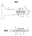
- the key comprises a key head 2, visible in part, and a host 4 adapted to be inserted into a lock cylinder.
- An intermediate neck 6 is formed between the head and the langlage and has at its junction with the reception two shoulders forming a stop for stopping in position of the key when it is inserted into the lock cylinder.
- the reception 4 has a flat shape, here of rectangular section, and it has a free front end 8 arranged axially opposite the neck, here cut to a point.
- the reception comprises two slices 10 and 12 and two main faces 14 and 16.
- the reception comprises a window 18 which forms an opening passing through the key from one face to the other and extending axially along the langlage in a centered manner, that is to say at equidistance of the slices. It is understood that in this arrangement, the median axis of the window coincides with the median axis of the langlage.
- Rollers 20 are arranged in the window. They are mounted around an axis 22 disposed transversely to the window. They are in the example illustrated in number of four, arranged successively along the window.
- Each of the axes of rotation is mounted in a blind hole, which extends transversely from one of the slices of equidistant reception of the two faces.
- the axis of rotation is threaded into the blind hole by this slice, until it is in abutment at the bottom of the blind hole. This has a depth such that the bottom of the blind hole is located transversely beyond the window, so that the axis threaded into this hole through the window.
- each roller is rotatably mounted about its axis which is arranged transversely to the median axis of the langlage, so that each roller is adapted to rotate in a direction parallel to this median axis of the langlage, which corresponds to the direction of insertion of the langlage in the lock cylinder.
- this facilitates the insertion and release of the key relative to the lock cylinder.
- the key according to the invention may comprise rollers locked in rotation on their respective axis.
- the roller here takes the form of a roller in the right cylinder, it being understood that it may alternatively take other forms as soon as it fulfills its role of cooperation with the associated pin of the lock cylinder, and that allows the passage of the pins during the insertion of the key.
- the right cylindrical shape is the most adapted to cooperate with the end of the pins when they are oriented radially in the rotor, obliquely to the generatrix of the cylindrical periphery of the roller.
- the rollers may be of different diameters. According to their diameters, the rollers exceed or not on both sides of the langlage. Thus, the roller exceeds the plastlage when its diameter is greater than the thickness of the langlage, while it is entirely contained in the thickness of the plastlage when its diameter is smaller than that of the langlage. It is understood that since the axis of rotation is threaded into a blind hole which extends equidistant from the faces of the langlage, the roller exceeds the same distance relative to each of the faces of the langlage.
- the distance between two adjacent pebbles remains the same all along the window. It is understood that without departing from the context of the invention, the values of these distances may be distinct. We have referenced on the figure 2 the distances between d1, d2 and d3 respectively and it is understood that they can take an arbitrary value chosen by the locksmith, since these values make it possible to ensure that two rollers can be arranged side by side without touching each other, whatever their diameters.
- the number of rollers here equal to four, can vary and this variable number, combined with the different available sizes of each of them, generates a multiplicity of possible combinations, which offers a large choice of signature of this type of key.
- the reception may also include impressions made in the thickness of the URIlage, so as to form depressions of different dimensions and depth, as may be known in previous achievements.
- these fingerprints are advantageously provided (some of which have been illustrated by way of example on figures 1 , 3 or 5 ) comprise first indentations 24 dug more or less deep relative to the plane of the faces of the URIlage, and second indentations 25 made by erosion of the edges formed between a face and a slice of the key.
- the imprints are distributed symmetrically with respect to the central axis of the key passing through the center of the rollers so as to provide a reversibility of the key is that is to say to allow the insertion of the URIlage of the key indifferently in one direction or in the other. It is understood that these fingerprints are positioned to take into consideration the presence of the window on the faces and the presence of the blind holes on the slices.
- the second indentations disposed on the edges are offset axially relative to the blind holes associated with the rollers so as not to interfere with the axes housed in these holes.
- This method comprises three distinctive successive steps, namely a first machining step in which one seeks to obtain the basic elements of the key, a second assembly step in which the signature of the key according to the invention is created, specific in that it corresponds to a lock cylinder, by assembling in a given configuration the different components of the specific key, and a last machining step in which additional fingerprinting operations are performed on the receiver.
- the first step is machining on the key of the window and blind holes. This results in a standard key model, different from conventional keys by the presence of the particular window, but which can be used for different key models according to the invention.
- the axes are also manufactured, adapted to be threaded into the blind holes during assembly, and each of the axes is machined in a standard manner, to have a diameter and a given length.
- rollers which have different diameters to adapt to the specific needs for each key.
- the variure of the key is obtained in the second step by mounting at least one roller of specific diameter in the window.
- the number of rollers, their respective diameters, their spacing and their arrangement from one end to the other of the window offers a multitude of possible signatures that gives the key its authenticity and traceability.
- the roller For each of the rollers to be mounted, the roller is held in place in the window at one of the blind holes while threading an axis of rotation in the blind hole so that this axis passes into the bore of the roller.
- the axis When the axis is in abutment against the bottom of the blind hole, it blocks the position of the axis by crushing the edge of the blind hole receiving the axis to reduce the opening diameter of the hole and immobilize the axis.
- This attachment crushing edges has the advantage in the case considered to prohibit any subsequent disassembly of the key.
- the signature which is unique to this key and which makes it unique, and which thus contributes to the security of the lock assembly of which it forms part, is furthermore obtained by machining impressions in the third step.
- the positioning scheme of these fingerprints is specific to the key, and it corresponds to a specific arrangement of the cooperating elements that comprises the lock cylinder to which the key corresponds.
- a plurality of first impressions is made on the faces around the window and a plurality of second impressions is made on the edges.
- the first and second indentations are axially offset to allow the arrangement of the corresponding pins in the cylinder. All of these impressions and the interchangeability of the rollers makes it possible to obtain a large number of possible signatures.
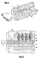
- a key according to the invention is provided to cooperate with a specific lock cylinder 26 in particular that it comprises a series of pins adapted to cooperate with the series of rollers.
- the cylinder comprises a rotor 28 adapted to rotate inside a stator 30.
- the rotor has a slot 45 in which the key is adapted to be inserted.
- This slot has two grooves 46, arranged symmetrically on both sides of the slot, substantially in the center thereof.
- the slot is also offset with respect to the axis of the cylinder on a diameter of the cylinder, as can be seen on the figure 3 .
- First bores 32 are made in the cylinder, extending radially from outside the stator to the slot of the rotor, having two parts respectively machined in the rotor and in the stator.
- An assembly formed by a pin 34 and a counter-pin 36, independent of each other, is installed in each of the radial bores, pushed towards the inside of the cylinder by a spring 38, resting on the counterbore. pin.
- the first bore has at its bottom a shoulder that allows passage to a pin head so that it can come into contact with the key and which forms a stop for the body of the pin against the thrust of the spring.
- This pin head, opposite the pin against has a rounded tip, substantially shaped spherical cap. This shape is particularly well suited for pins that come to face the periphery of the rollers mounted in the axis of the key.
- the proximal bore formed in the rotor is angularly positioned in the cylinder. extending the distal bore formed in the stator, so that the pin and its associated cotter pin can slide along the bore formed by these two parts together.
- the pin is pushed into the rotor under the action of the spring resting on the counter-pin, so that, in the rest position, without a key inserted into the cylinder, the counter-pin extends into part in the rotor and partly in the stator, thereby blocking the rotation of the rotor relative to the stator.
- the pin and the cotter pin are two separable elements, which have one convex contact face 40 complementary to the concave contact face 42 of the other. These faces have a radius of curvature substantially equal to the radius of the rotor.
- the rotor is thus adapted to rotate inside the stator when the faces of pin and counter-pin contact are positioned at the junction between the rotor and the stator.
- the movement of the rotor in the stator can be achieved only when all the pins have been placed at the correct height in their radial bore, so that only the pins are in the rotor and that only the counter-pins are in the stator.
- the langlage acts on the pin mainly by pushing the pin heads to the stator, and thus compressing the spring through the counter-pin.
- the different pins are pushed by the counter-pins to the bottom of the corresponding impressions, and if the imprint has the right place and the right dimensions, the assembly formed by the pin and the counter-pin s adjusts in radial position so that their facing faces are at the junction between the rotor and the stator, which can freely rotate.
- Fingerprints of different depths and rollers of different diameters will be made to obtain a unique key that corresponds to the dimensions of the pins arranged uniquely in the lock cylinder.
- first pins 34 housed in first bores 32, are arranged to be actuated by the first indentations 24 made on one side and that other pins, second pins housed in second bores 35 and not shown on the figure 5 to clarify the reading of this figure, are arranged to be actuated by the second imprints 25 made on an edge.
- the invention also extends to an embodiment not shown, wherein at least some of the rollers has an annular groove dug around the periphery of the roller.
- This groove can be advantageously asymmetrical hollow profile like other fingerprints of the key to cooperate better with pins penetrating diagonally in. It is noted that such a groove is fully compatible with the role of rolling guide such a roller to facilitate insertion of the key to its position cooperating with the cylinder. All that is needed for this is that the groove is hollowed out in a central part of the roller leaving on both sides the original cylindrical profile.
- the lock cylinder comprises a specific series of pins, in which each of the pins is adapted to cooperate with one of the rollers carried by the key described above.
- the second bores 33 corresponding to this specific series extend along an axis inclined relative to the normal to the axis of rotation of the rollers so as to point on the axis of rotation of the rotor (as visible on the figure 5 ).
- the pins and cotter pins adapted to slide in these bores can be disposed on either side of the curved junction plane between the rotor and the stator.
- the arrangement of the lock assembly according to the invention thus makes it possible to dispose in a reduced space of five distinct sets of pins axially aligned, each of these pins pointing to the axis of rotation of the rotor to facilitate the cooperation of the pins and the cylinder for locking and unlocking the rotor and the stator.
- the set of pins associated with the rollers is arranged in the lower half of the roll, so that four sets of pins can advantageously be concentrated in the upper half of the roll and the number of possible combinations for unlocking the rotor and the roll can be increased.
- stator in the cylinder for this purpose, the two sets of pins associated with the first impressions made on the faces of the langlage are offset axially with respect to the two sets of pins associated with the second imprints made on the edges of the langlage.
- a number of rollers mounted on the key at least equivalent to the number of pins arranged in series in the cylinder are specifically provided to be actuated by these rollers.
- the sizes of the rollers are chosen in correspondence with the shape and the dimension of the pins so that they are correctly retracted when the key is inserted in abutment in the slot of the cylinder, in order to allow rotation of the rotor.
- the diameter of the rollers is chosen in correspondence with the dimension of the pins.
- some pins may be arranged to protrude further into the slot than other pins, and these pins are made to be smaller diameter rollers than the others.
- the fact that each of the rollers is mounted free to rotate about its axis allows easy insertion of the key without abutting the pin heads protruding into the slot.
- a large-diameter roller radially pushes these pin heads without difficulty until it is in contact with the corresponding one when the key is in abutment in the lock cylinder, and pin heads pushed radially to the passage of the key are replaced in their original position under the effect of the spring when the large diameter roller has passed.
- the large diameter rollers protruding from either side of the receiver slide in the grooves arranged symmetrically to on both sides of the slot.
- These grooves are sized to allow the passage of the larger diameter roller, and they serve as a centering means and guide to the insertion of the key.
- the insert has a cylindrical or spherical shape, rotatably mounted, and this has the advantage of minimizing friction against the pins which protrude into the slot on the passage of the key when inserted into the lock cylinder. .
- Each roller is arranged to rotate in a direction parallel to the direction of insertion of the host in the lock cylinder which facilitates the movement of the key in the lock cylinder, both insertion and release since the key is free in rotation.
- This cylindrical or spherical shape further facilitates the design of a reversible key.
- the fact that the signature of the key is obtained in particular through the combination of reported elements allows a standardization of production of the basic elements of the key while allowing a control of the reproduction of the keys, by the unalterable side of the factory assembly of the rollers in the key, and by the multitude of possible combinations of these elements.
Landscapes
- Lock And Its Accessories (AREA)
Priority Applications (1)
| Application Number | Priority Date | Filing Date | Title |
|---|---|---|---|
| US14/331,887 US9151077B2 (en) | 2013-01-15 | 2014-07-15 | Key and cylinder locking assembly corresponding to said key |
Applications Claiming Priority (1)
| Application Number | Priority Date | Filing Date | Title |
|---|---|---|---|
| FR1300072A FR3000982B1 (fr) | 2013-01-15 | 2013-01-15 | Cle de serrurerie et ensemble de serrurerie a cylindre correspondant a une telle cle |
Publications (2)
| Publication Number | Publication Date |
|---|---|
| EP2754792A1 true EP2754792A1 (de) | 2014-07-16 |
| EP2754792B1 EP2754792B1 (de) | 2020-01-15 |
Family
ID=48044837
Family Applications (1)
| Application Number | Title | Priority Date | Filing Date |
|---|---|---|---|
| EP14000142.1A Active EP2754792B1 (de) | 2013-01-15 | 2014-01-15 | Schlüssel und zylinderschlossvorrichtung übereinstimmend mit diesem schlüssel |
Country Status (3)
| Country | Link |
|---|---|
| EP (1) | EP2754792B1 (de) |
| CA (1) | CA2839892C (de) |
| FR (1) | FR3000982B1 (de) |
Cited By (4)
| Publication number | Priority date | Publication date | Assignee | Title |
|---|---|---|---|---|
| DE102014010707A1 (de) * | 2014-07-17 | 2016-01-21 | Assa Abloy Sicherheitstechnik Gmbh | Schloss-Schlüssel-System |
| DE202016003806U1 (de) | 2015-07-22 | 2016-07-27 | Dom Sicherheitstechnik Gmbh & Co. Kg | Schlüssel für einen Schließzylinder und Schließvorrichtung |
| EP3354826A1 (de) | 2017-01-30 | 2018-08-01 | DOM-Sicherheitstechnik GmbH & Co. KG | Verbesserter schlüssel für einen schliesszylinder, schliessvorrichtung und verfahren |
| CN113665340A (zh) * | 2021-08-25 | 2021-11-19 | 湖南牛顺科技有限公司 | 一种锁止机构、电池箱托架及电动重卡 |
Citations (5)
| Publication number | Priority date | Publication date | Assignee | Title |
|---|---|---|---|---|
| FR2759406A1 (fr) * | 1997-02-13 | 1998-08-14 | Silca France Sa | Ensemble de surete constitue par l'association d'une cle plate standard et d'un barillet ainsi que cle plate faisant partie integrante d'un tel ensemble |
| WO1999064703A1 (en) * | 1998-06-05 | 1999-12-16 | Mottura Serrature Di Sicurezza S.P.A. | Cylinder lock |
| WO2002042582A1 (en) * | 2000-11-25 | 2002-05-30 | Dom Sicherheitstechnik Gmbh & Co Kg | Key and associated lock cylinder |
| EP1662077A1 (de) * | 2004-11-30 | 2006-05-31 | Titan Tovarna kovinskih izdelkov in livarna d.d., Kamnik | Flachschlüssel mit zusätzlichem Sicherheitselement |
| WO2009012541A1 (en) * | 2007-07-25 | 2009-01-29 | 'mauer Locking Systems'ltd | Cylinder lock and associated key and key blank therefor |
-
2013
- 2013-01-15 FR FR1300072A patent/FR3000982B1/fr active Active
-
2014
- 2014-01-15 CA CA2839892A patent/CA2839892C/fr active Active
- 2014-01-15 EP EP14000142.1A patent/EP2754792B1/de active Active
Patent Citations (5)
| Publication number | Priority date | Publication date | Assignee | Title |
|---|---|---|---|---|
| FR2759406A1 (fr) * | 1997-02-13 | 1998-08-14 | Silca France Sa | Ensemble de surete constitue par l'association d'une cle plate standard et d'un barillet ainsi que cle plate faisant partie integrante d'un tel ensemble |
| WO1999064703A1 (en) * | 1998-06-05 | 1999-12-16 | Mottura Serrature Di Sicurezza S.P.A. | Cylinder lock |
| WO2002042582A1 (en) * | 2000-11-25 | 2002-05-30 | Dom Sicherheitstechnik Gmbh & Co Kg | Key and associated lock cylinder |
| EP1662077A1 (de) * | 2004-11-30 | 2006-05-31 | Titan Tovarna kovinskih izdelkov in livarna d.d., Kamnik | Flachschlüssel mit zusätzlichem Sicherheitselement |
| WO2009012541A1 (en) * | 2007-07-25 | 2009-01-29 | 'mauer Locking Systems'ltd | Cylinder lock and associated key and key blank therefor |
Cited By (10)
| Publication number | Priority date | Publication date | Assignee | Title |
|---|---|---|---|---|
| DE102014010707A1 (de) * | 2014-07-17 | 2016-01-21 | Assa Abloy Sicherheitstechnik Gmbh | Schloss-Schlüssel-System |
| DE102014010707B4 (de) * | 2014-07-17 | 2021-06-10 | Assa Abloy Sicherheitstechnik Gmbh | Schloss-Schlüssel-System |
| DE202016003806U1 (de) | 2015-07-22 | 2016-07-27 | Dom Sicherheitstechnik Gmbh & Co. Kg | Schlüssel für einen Schließzylinder und Schließvorrichtung |
| DE102015111914A1 (de) | 2015-07-22 | 2016-07-28 | Dom-Sicherheitstechnik Gmbh & Co. Kg | Schlüssel für einen Schließzylinder und Schließvorrichtung |
| EP3061893A2 (de) | 2015-07-22 | 2016-08-31 | DOM Sicherheitstechnik GmbH & Co. KG | Schlüssel für einen schliesszylinder und schliessvorrichtung |
| EP3301248A1 (de) | 2015-07-22 | 2018-04-04 | DOM-Sicherheitstechnik GmbH & Co. KG | Schlüssel für einen schliesszylinder und schliessvorrichtung |
| EP3354826A1 (de) | 2017-01-30 | 2018-08-01 | DOM-Sicherheitstechnik GmbH & Co. KG | Verbesserter schlüssel für einen schliesszylinder, schliessvorrichtung und verfahren |
| DE102017101783A1 (de) | 2017-01-30 | 2018-08-02 | Dom Sicherheitstechnik Gmbh & Co Kg | Verbesserter Schlüssel für einen Schließzylinder, Schließvorrichtung und Verfahren |
| CN113665340A (zh) * | 2021-08-25 | 2021-11-19 | 湖南牛顺科技有限公司 | 一种锁止机构、电池箱托架及电动重卡 |
| CN113665340B (zh) * | 2021-08-25 | 2023-12-01 | 湖南牛顺科技有限公司 | 一种锁止机构、电池箱托架及电动重卡 |
Also Published As
| Publication number | Publication date |
|---|---|
| FR3000982B1 (fr) | 2021-01-08 |
| CA2839892A1 (fr) | 2014-07-15 |
| EP2754792B1 (de) | 2020-01-15 |
| CA2839892C (fr) | 2020-07-14 |
| FR3000982A1 (fr) | 2014-07-18 |
Similar Documents
| Publication | Publication Date | Title |
|---|---|---|
| EP0154755B1 (de) | Schlüssel mit bewegbarer Bartstufe, Zylinder und Zylinderschloss dazu | |
| LU82606A1 (fr) | Serrure a barillet,cle pour cette serrure et procede de fabrication de la cle | |
| FR2704893A1 (fr) | Serrure de sûreté et clé plate pour une telle serrure. | |
| FR2949245A1 (fr) | Ensemble de verrou reconfigurable et procede de fonctionnement de cet ensemble | |
| LU82605A1 (fr) | Ensemble serrure a barillet et cle pour cette serrure et procede de fabrication de la cle | |
| CH646752A5 (fr) | Serrure a cylindre. | |
| WO2014111739A1 (fr) | Clé de serrurerie et ensemble de serrurerie a cylindre correspondant a une telle clé | |
| CA2839892C (fr) | Cle de serrurerie et ensemble de serrurerie a cylindre correspondant a une telle cle | |
| FR2737527A1 (fr) | Systeme de cle de serrure impossible a reproduire et de cylindre pour ladite cle | |
| EP0359885B1 (de) | Schlüssel mit Schiebeelement, Sicherheitszylinder, und Schloss mit solchen Zylindern | |
| EP2746499B1 (de) | Schlüssel und Vorrichtung für ihre Herstellung | |
| EP0983411B1 (de) | Schlüssel mit bewegbarem stift, sicherheitsdrehzylinder und damit ausgerüstetes schloss | |
| EP2003272B1 (de) | Schliesszylinder mit Doppelverriegelungssystem | |
| EP1767731B1 (de) | System aus Schlüssel und Schloss gegen eine unerlaubte Kopierung des Schlüssels | |
| EP3658724B1 (de) | Sicherheitsschloss und flachschlüsselanordnung | |
| EP2960406B1 (de) | Vorrichtung zum öffnen und schliessen eines artikels, insbesondere eines lederwaren-artikels, und artikel, der eine solche vorrichtung umfasst | |
| EP0700479B2 (de) | Schlüssel mit zwei abschrägungen am ende für ein sicherheitzylinderschloss und zylinderschloss dafür | |
| EP3498944B1 (de) | Schlüssel und zylinder für sicherheitsschloss | |
| FR3072704B1 (fr) | Procede de codage d’ensembles clef / verrou pour dispositif de fermeture | |
| FR2669366A1 (fr) | Cle a empreintes non reproductibles et barillet pour ladite cle. | |
| FR2802234A1 (fr) | Barillet de surete muni d'un moyen anti-crochetage | |
| FR2802233A1 (fr) | Barillet de surete muni d'un moyen anti-vibreur | |
| EP1454024B1 (de) | Verriegelungsvorrichtungs-sicherheitsschloss | |
| FR2531127A1 (fr) | Serrure a pompe equipee d'un collier mobile anti-crochetage avec delateur et piege | |
| FR2522352A1 (fr) | Serrure a cylindre, a combinaison sans cle |
Legal Events
| Date | Code | Title | Description |
|---|---|---|---|
| PUAI | Public reference made under article 153(3) epc to a published international application that has entered the european phase |
Free format text: ORIGINAL CODE: 0009012 |
|
| 17P | Request for examination filed |
Effective date: 20140115 |
|
| AK | Designated contracting states |
Kind code of ref document: A1 Designated state(s): AL AT BE BG CH CY CZ DE DK EE ES FI FR GB GR HR HU IE IS IT LI LT LU LV MC MK MT NL NO PL PT RO RS SE SI SK SM TR |
|
| AX | Request for extension of the european patent |
Extension state: BA ME |
|
| R17P | Request for examination filed (corrected) |
Effective date: 20150106 |
|
| RAX | Requested extension states of the european patent have changed |
Extension state: BA Payment date: 20150106 Extension state: ME Payment date: 20150106 |
|
| STAA | Information on the status of an ep patent application or granted ep patent |
Free format text: STATUS: EXAMINATION IS IN PROGRESS |
|
| 17Q | First examination report despatched |
Effective date: 20180119 |
|
| RAP1 | Party data changed (applicant data changed or rights of an application transferred) |
Owner name: GROUPE VALENTE |
|
| RIN1 | Information on inventor provided before grant (corrected) |
Inventor name: MIGLIASSO, MARCO Inventor name: VALENTE, MASSIMO |
|
| RIC1 | Information provided on ipc code assigned before grant |
Ipc: E05B 19/00 20060101AFI20190626BHEP Ipc: E05B 35/00 20060101ALI20190626BHEP Ipc: E05B 17/00 20060101ALN20190626BHEP |
|
| GRAP | Despatch of communication of intention to grant a patent |
Free format text: ORIGINAL CODE: EPIDOSNIGR1 |
|
| STAA | Information on the status of an ep patent application or granted ep patent |
Free format text: STATUS: GRANT OF PATENT IS INTENDED |
|
| RIC1 | Information provided on ipc code assigned before grant |
Ipc: E05B 35/00 20060101ALI20190703BHEP Ipc: E05B 19/00 20060101AFI20190703BHEP Ipc: E05B 17/00 20060101ALN20190703BHEP |
|
| INTG | Intention to grant announced |
Effective date: 20190805 |
|
| GRAS | Grant fee paid |
Free format text: ORIGINAL CODE: EPIDOSNIGR3 |
|
| GRAA | (expected) grant |
Free format text: ORIGINAL CODE: 0009210 |
|
| STAA | Information on the status of an ep patent application or granted ep patent |
Free format text: STATUS: THE PATENT HAS BEEN GRANTED |
|
| AK | Designated contracting states |
Kind code of ref document: B1 Designated state(s): AL AT BE BG CH CY CZ DE DK EE ES FI FR GB GR HR HU IE IS IT LI LT LU LV MC MK MT NL NO PL PT RO RS SE SI SK SM TR |
|
| AX | Request for extension of the european patent |
Extension state: BA ME |
|
| REG | Reference to a national code |
Ref country code: CH Ref legal event code: EP Ref country code: GB Ref legal event code: FG4D Free format text: NOT ENGLISH |
|
| REG | Reference to a national code |
Ref country code: IE Ref legal event code: FG4D Free format text: LANGUAGE OF EP DOCUMENT: FRENCH |
|
| REG | Reference to a national code |
Ref country code: DE Ref legal event code: R096 Ref document number: 602014059958 Country of ref document: DE |
|
| REG | Reference to a national code |
Ref country code: AT Ref legal event code: REF Ref document number: 1225287 Country of ref document: AT Kind code of ref document: T Effective date: 20200215 |
|
| REG | Reference to a national code |
Ref country code: NL Ref legal event code: MP Effective date: 20200115 |
|
| REG | Reference to a national code |
Ref country code: LT Ref legal event code: MG4D |
|
| PG25 | Lapsed in a contracting state [announced via postgrant information from national office to epo] |
Ref country code: PT Free format text: LAPSE BECAUSE OF FAILURE TO SUBMIT A TRANSLATION OF THE DESCRIPTION OR TO PAY THE FEE WITHIN THE PRESCRIBED TIME-LIMIT Effective date: 20200607 Ref country code: RS Free format text: LAPSE BECAUSE OF FAILURE TO SUBMIT A TRANSLATION OF THE DESCRIPTION OR TO PAY THE FEE WITHIN THE PRESCRIBED TIME-LIMIT Effective date: 20200115 Ref country code: FI Free format text: LAPSE BECAUSE OF FAILURE TO SUBMIT A TRANSLATION OF THE DESCRIPTION OR TO PAY THE FEE WITHIN THE PRESCRIBED TIME-LIMIT Effective date: 20200115 Ref country code: NL Free format text: LAPSE BECAUSE OF FAILURE TO SUBMIT A TRANSLATION OF THE DESCRIPTION OR TO PAY THE FEE WITHIN THE PRESCRIBED TIME-LIMIT Effective date: 20200115 Ref country code: NO Free format text: LAPSE BECAUSE OF FAILURE TO SUBMIT A TRANSLATION OF THE DESCRIPTION OR TO PAY THE FEE WITHIN THE PRESCRIBED TIME-LIMIT Effective date: 20200415 |
|
| REG | Reference to a national code |
Ref country code: DE Ref legal event code: R119 Ref document number: 602014059958 Country of ref document: DE |
|
| PG25 | Lapsed in a contracting state [announced via postgrant information from national office to epo] |
Ref country code: LV Free format text: LAPSE BECAUSE OF FAILURE TO SUBMIT A TRANSLATION OF THE DESCRIPTION OR TO PAY THE FEE WITHIN THE PRESCRIBED TIME-LIMIT Effective date: 20200115 Ref country code: SE Free format text: LAPSE BECAUSE OF FAILURE TO SUBMIT A TRANSLATION OF THE DESCRIPTION OR TO PAY THE FEE WITHIN THE PRESCRIBED TIME-LIMIT Effective date: 20200115 Ref country code: GR Free format text: LAPSE BECAUSE OF FAILURE TO SUBMIT A TRANSLATION OF THE DESCRIPTION OR TO PAY THE FEE WITHIN THE PRESCRIBED TIME-LIMIT Effective date: 20200416 Ref country code: HR Free format text: LAPSE BECAUSE OF FAILURE TO SUBMIT A TRANSLATION OF THE DESCRIPTION OR TO PAY THE FEE WITHIN THE PRESCRIBED TIME-LIMIT Effective date: 20200115 Ref country code: IS Free format text: LAPSE BECAUSE OF FAILURE TO SUBMIT A TRANSLATION OF THE DESCRIPTION OR TO PAY THE FEE WITHIN THE PRESCRIBED TIME-LIMIT Effective date: 20200515 Ref country code: BG Free format text: LAPSE BECAUSE OF FAILURE TO SUBMIT A TRANSLATION OF THE DESCRIPTION OR TO PAY THE FEE WITHIN THE PRESCRIBED TIME-LIMIT Effective date: 20200415 |
|
| REG | Reference to a national code |
Ref country code: CH Ref legal event code: PL |
|
| REG | Reference to a national code |
Ref country code: BE Ref legal event code: MM Effective date: 20200131 |
|
| PG25 | Lapsed in a contracting state [announced via postgrant information from national office to epo] |
Ref country code: RO Free format text: LAPSE BECAUSE OF FAILURE TO SUBMIT A TRANSLATION OF THE DESCRIPTION OR TO PAY THE FEE WITHIN THE PRESCRIBED TIME-LIMIT Effective date: 20200115 Ref country code: SK Free format text: LAPSE BECAUSE OF FAILURE TO SUBMIT A TRANSLATION OF THE DESCRIPTION OR TO PAY THE FEE WITHIN THE PRESCRIBED TIME-LIMIT Effective date: 20200115 Ref country code: DE Free format text: LAPSE BECAUSE OF NON-PAYMENT OF DUE FEES Effective date: 20200801 Ref country code: LT Free format text: LAPSE BECAUSE OF FAILURE TO SUBMIT A TRANSLATION OF THE DESCRIPTION OR TO PAY THE FEE WITHIN THE PRESCRIBED TIME-LIMIT Effective date: 20200115 Ref country code: ES Free format text: LAPSE BECAUSE OF FAILURE TO SUBMIT A TRANSLATION OF THE DESCRIPTION OR TO PAY THE FEE WITHIN THE PRESCRIBED TIME-LIMIT Effective date: 20200115 Ref country code: CZ Free format text: LAPSE BECAUSE OF FAILURE TO SUBMIT A TRANSLATION OF THE DESCRIPTION OR TO PAY THE FEE WITHIN THE PRESCRIBED TIME-LIMIT Effective date: 20200115 Ref country code: DK Free format text: LAPSE BECAUSE OF FAILURE TO SUBMIT A TRANSLATION OF THE DESCRIPTION OR TO PAY THE FEE WITHIN THE PRESCRIBED TIME-LIMIT Effective date: 20200115 Ref country code: LU Free format text: LAPSE BECAUSE OF NON-PAYMENT OF DUE FEES Effective date: 20200115 Ref country code: EE Free format text: LAPSE BECAUSE OF FAILURE TO SUBMIT A TRANSLATION OF THE DESCRIPTION OR TO PAY THE FEE WITHIN THE PRESCRIBED TIME-LIMIT Effective date: 20200115 Ref country code: SM Free format text: LAPSE BECAUSE OF FAILURE TO SUBMIT A TRANSLATION OF THE DESCRIPTION OR TO PAY THE FEE WITHIN THE PRESCRIBED TIME-LIMIT Effective date: 20200115 Ref country code: MC Free format text: LAPSE BECAUSE OF FAILURE TO SUBMIT A TRANSLATION OF THE DESCRIPTION OR TO PAY THE FEE WITHIN THE PRESCRIBED TIME-LIMIT Effective date: 20200115 |
|
| REG | Reference to a national code |
Ref country code: AT Ref legal event code: MK05 Ref document number: 1225287 Country of ref document: AT Kind code of ref document: T Effective date: 20200115 |
|
| PLBE | No opposition filed within time limit |
Free format text: ORIGINAL CODE: 0009261 |
|
| STAA | Information on the status of an ep patent application or granted ep patent |
Free format text: STATUS: NO OPPOSITION FILED WITHIN TIME LIMIT |
|
| PG25 | Lapsed in a contracting state [announced via postgrant information from national office to epo] |
Ref country code: BE Free format text: LAPSE BECAUSE OF NON-PAYMENT OF DUE FEES Effective date: 20200131 Ref country code: CH Free format text: LAPSE BECAUSE OF NON-PAYMENT OF DUE FEES Effective date: 20200131 Ref country code: LI Free format text: LAPSE BECAUSE OF NON-PAYMENT OF DUE FEES Effective date: 20200131 |
|
| 26N | No opposition filed |
Effective date: 20201016 |
|
| PG25 | Lapsed in a contracting state [announced via postgrant information from national office to epo] |
Ref country code: AT Free format text: LAPSE BECAUSE OF FAILURE TO SUBMIT A TRANSLATION OF THE DESCRIPTION OR TO PAY THE FEE WITHIN THE PRESCRIBED TIME-LIMIT Effective date: 20200115 Ref country code: IE Free format text: LAPSE BECAUSE OF NON-PAYMENT OF DUE FEES Effective date: 20200115 Ref country code: IT Free format text: LAPSE BECAUSE OF FAILURE TO SUBMIT A TRANSLATION OF THE DESCRIPTION OR TO PAY THE FEE WITHIN THE PRESCRIBED TIME-LIMIT Effective date: 20200115 |
|
| PG25 | Lapsed in a contracting state [announced via postgrant information from national office to epo] |
Ref country code: SI Free format text: LAPSE BECAUSE OF FAILURE TO SUBMIT A TRANSLATION OF THE DESCRIPTION OR TO PAY THE FEE WITHIN THE PRESCRIBED TIME-LIMIT Effective date: 20200115 Ref country code: PL Free format text: LAPSE BECAUSE OF FAILURE TO SUBMIT A TRANSLATION OF THE DESCRIPTION OR TO PAY THE FEE WITHIN THE PRESCRIBED TIME-LIMIT Effective date: 20200115 |
|
| GBPC | Gb: european patent ceased through non-payment of renewal fee |
Effective date: 20200415 |
|
| PG25 | Lapsed in a contracting state [announced via postgrant information from national office to epo] |
Ref country code: GB Free format text: LAPSE BECAUSE OF NON-PAYMENT OF DUE FEES Effective date: 20200415 |
|
| PG25 | Lapsed in a contracting state [announced via postgrant information from national office to epo] |
Ref country code: TR Free format text: LAPSE BECAUSE OF FAILURE TO SUBMIT A TRANSLATION OF THE DESCRIPTION OR TO PAY THE FEE WITHIN THE PRESCRIBED TIME-LIMIT Effective date: 20200115 Ref country code: MT Free format text: LAPSE BECAUSE OF FAILURE TO SUBMIT A TRANSLATION OF THE DESCRIPTION OR TO PAY THE FEE WITHIN THE PRESCRIBED TIME-LIMIT Effective date: 20200115 Ref country code: CY Free format text: LAPSE BECAUSE OF FAILURE TO SUBMIT A TRANSLATION OF THE DESCRIPTION OR TO PAY THE FEE WITHIN THE PRESCRIBED TIME-LIMIT Effective date: 20200115 |
|
| PG25 | Lapsed in a contracting state [announced via postgrant information from national office to epo] |
Ref country code: MK Free format text: LAPSE BECAUSE OF FAILURE TO SUBMIT A TRANSLATION OF THE DESCRIPTION OR TO PAY THE FEE WITHIN THE PRESCRIBED TIME-LIMIT Effective date: 20200115 Ref country code: AL Free format text: LAPSE BECAUSE OF FAILURE TO SUBMIT A TRANSLATION OF THE DESCRIPTION OR TO PAY THE FEE WITHIN THE PRESCRIBED TIME-LIMIT Effective date: 20200115 |
|
| PGFP | Annual fee paid to national office [announced via postgrant information from national office to epo] |
Ref country code: FR Payment date: 20260122 Year of fee payment: 13 |