EP2754792B1 - Schlüssel und zylinderschlossvorrichtung übereinstimmend mit diesem schlüssel - Google Patents
Schlüssel und zylinderschlossvorrichtung übereinstimmend mit diesem schlüssel Download PDFInfo
- Publication number
- EP2754792B1 EP2754792B1 EP14000142.1A EP14000142A EP2754792B1 EP 2754792 B1 EP2754792 B1 EP 2754792B1 EP 14000142 A EP14000142 A EP 14000142A EP 2754792 B1 EP2754792 B1 EP 2754792B1
- Authority
- EP
- European Patent Office
- Prior art keywords
- key
- rollers
- pins
- blade
- roller
- Prior art date
- Legal status (The legal status is an assumption and is not a legal conclusion. Google has not performed a legal analysis and makes no representation as to the accuracy of the status listed.)
- Active
Links
Images


Classifications
-
- E—FIXED CONSTRUCTIONS
- E05—LOCKS; KEYS; WINDOW OR DOOR FITTINGS; SAFES
- E05B—LOCKS; ACCESSORIES THEREFOR; HANDCUFFS
- E05B19/00—Keys; Accessories therefor
- E05B19/0017—Key profiles
-
- E—FIXED CONSTRUCTIONS
- E05—LOCKS; KEYS; WINDOW OR DOOR FITTINGS; SAFES
- E05B—LOCKS; ACCESSORIES THEREFOR; HANDCUFFS
- E05B35/00—Locks for use with special keys or a plurality of keys ; keys therefor
- E05B35/003—Locks for use with special keys or a plurality of keys ; keys therefor for keys with movable bits
- E05B35/004—Locks for use with special keys or a plurality of keys ; keys therefor for keys with movable bits pivoting about an axis perpendicular to the main key axis
-
- E—FIXED CONSTRUCTIONS
- E05—LOCKS; KEYS; WINDOW OR DOOR FITTINGS; SAFES
- E05B—LOCKS; ACCESSORIES THEREFOR; HANDCUFFS
- E05B17/00—Accessories in connection with locks
- E05B17/007—Devices for reducing friction between lock parts
Definitions
- the present invention lies in the field of security locksmithing, in which it is sought to control the reproduction of keys.
- the invention relates to a security key as well as a locksmith assembly formed by such a key and by a lock cylinder with which the key is intended to cooperate.
- the lock assembly comprises a key and a lock cylinder comprising a rotor and a stator, as well as a set of pins and counter pins allowing, by their respective positioning, the locking or unlocking of the rotation of the rotor in the stator.
- the key according to the invention conventionally comprises a key head and a receptacle adapted to be inserted into a slot in the lock cylinder. It is preferable to use keys for point systems, in which the socket carries in its thickness indentations to cooperate, when the socket is inserted in the lock cylinder, with the pins of the lock cylinder.
- the pins are arranged in bores arranged radially in the cylinder, said pins being movable in translation in their respective bores under the effect of a spring tending to push it towards the center of the lock cylinder and in the opposite direction under it. effect of the presence of the key when it is in place in its cylinder.
- each of the pins enters the imprint which is respectively associated with it.
- the pins are positioned in an open position in which they allow the rotation of the rotor in the stator of the cylinder and therefore the opening of the lock.
- the present invention proposes means for carrying out the signing of security keys differently, which involve a window formed in the axis of the reception to place therein a series of rollers centered across the window, as mentioned in the document. TW 200 825 259 .
- the invention is defined in claim 1. It differs mainly from this document by the fact that the various rollers are mounted freely rotatable around respective axes which are fixed in the reception.
- roller is mounted free to rotate about its axis, so that it promotes sliding on the pins which are in the path of the key when it is inserted into the slot. It will be understood that this easier sliding takes place both in the direction of insertion of the key and in the direction of withdrawal of the latter.
- the invention also provides a locksmith assembly comprising a key according to the invention and a lock cylinder comprising a rotor and a stator, as well as a set of pins and counter-pins allowing, by their respective positioning, locking or unlocking. the rotation of the rotor in the stator.
- pins are specially arranged sliding radially in the rotor to each correspond with a roller of the security key when this key is in its stop position in the lock cylinder.
- a set of rollers arranged axially in series in the window made in the thickness of the reception of the key, and there is provided a corresponding set of pins in the lock cylinder, the number of these pins being equivalent to the number of rollers, and the spacing between each pin in their axial arrangement being equivalent to the spacing between each of the rollers.
- the pins will be more or less driven inside the rotor depending on whether they must correspond when the key is in its stop position with a roller of more or less large diameter.
- the slot made in the lock cylinder for the passage of the key has two grooves arranged symmetrically on the side and other of the slot to allow the passage of the rollers of larger diameter than the thickness of the reception, and which therefore extend projecting from this reception.
- the two grooves arranged on either side of the slot thus form a guide path in which the peripheries of the rollers roll.
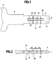
- the key comprises a key head 2, partially visible, and a socket 4 adapted to be inserted in a lock cylinder.
- An intermediate neck 6 is formed between the head and the reception and it has at its junction with the reception two shoulders forming a stop for stopping the key in position when it is inserted in the lock cylinder.
- the socket 4 has a flat shape, here of rectangular section, and it has a free front end 8 disposed axially opposite the neck, here cut into a point.
- the reception comprises two sections 10 and 12 and two main faces 14 and 16.
- the reception comprises a window 18 which forms an opening passing through the key from one face to the other and extending axially along the reception in a centered manner, that is to say at equidistance of the slices. It is understood that in this arrangement, the median axis of the window coincides with the median axis of the reception.
- Rollers 20 are arranged in the window. They are mounted around an axis 22 arranged transversely to the window. In the example illustrated, there are four of them, arranged successively along the window.
- Each of the axes of rotation is mounted in a blind hole, which extends transversely from one of the edges of the housing equidistant from the two faces.
- the axis of rotation is threaded into the blind hole by this section, until it is in abutment at the bottom of the blind hole. This has a depth such that the bottom of the blind hole is located transversely beyond the window, so that the axis threaded into this hole passes through the window.
- each roller is mounted to rotate freely about its axis which is arranged transversely to the median axis of the holder, so that each roller is adapted to rotate in a direction parallel to this median axis of l 'reception, which corresponds to the direction of insertion of the reception into the lock cylinder.
- this makes it easier to insert and disengage the key from the lock cylinder.
- the key according to the invention may include rollers locked in rotation on their respective axis.
- the roller here takes the form of a roller in a straight cylinder, it being understood that it may alternatively take other forms as soon as it fulfills its role of cooperation with the associated pin of the lock cylinder, and it allows the passage of pins when inserting the key.
- the straight cylindrical shape is the most suitable for cooperating with the end of the pins when the latter are oriented radially in the rotor, at an angle to the generator of the cylindrical periphery of the roller.
- the rollers can be of different diameters. Depending on their diameters, the rollers may or may not protrude on either side of the reception. Thus, the roller protrudes from the reception when its diameter is greater than the thickness of the reception, while it is entirely contained in the thickness of the reception when its diameter is less than that of the reception. It is understood that since the axis of rotation is threaded into a blind hole which extends equidistant from the faces of the reception, the roller exceeds the same distance relative to each of the faces of the reception.
- the distance between two neighboring rollers remains the same all along the window. It is understood that without departing from the context of the invention, the values of these centers can be distinct. We thus referenced on the figure 2 the centers respectively d1, d2 and d3 and it is understood that they can take an arbitrary value chosen by the locksmith, since these values ensure that two rollers can be arranged side by side without touching, whatever their diameters.
- the number of rollers here equal to four, can vary and this variable number, combined with the different sizes available for each of them, generates a multiplicity of possible combinations, which offers a large choice of signature for this type of key.
- the reception can also include imprints made in the thickness of the reception, so as to form depressions of different dimensions and depth, as may be known in the previous embodiments.
- these fingerprints (some of which have been illustrated by way of example on the figures 1 , 3 or 5 ) comprise first indentations 24 dug more or less deeply relative to the plane of the faces of the reception, and second indentations 25 produced by erosion of the edges formed between a face and a slice of the key.
- the imprints are distributed symmetrically with respect to the median axis of the key passing through the center of the rollers so as to offer a reversibility of the key, this is ie to allow the insertion of the reception of the key indifferently in one direction or the other. It is understood that these imprints are positioned so as to take into consideration the presence of the window on the faces and the presence of the blind holes on the edges.
- the second indentations 25 disposed on the edges are offset axially with respect to the blind holes associated with the rollers so as not to interfere with the axes housed in these holes.
- This process comprises three successive distinctive stages, namely a first machining stage in which it is sought to obtain the basic elements of the key, a second mounting stage in which the signature of the key according to the invention is created, specific in that it corresponds to a lock cylinder, by assembling in a given configuration the different components of the specific key, and a last machining step in which complementary operations of fingerprint formation are carried out on the reception.
- the first step consists of machining the window key and blind holes. This results in a standard key model, different from conventional keys in particular by the presence of the window, but which can be used for different key models according to the invention.
- the axes are also manufactured, adapted to be threaded into the blind holes during assembly, and each of the axes is machined in a standard manner, in order to have a given diameter and length.
- rollers are manufactured, which have different diameters to adapt to the specific needs for each of the keys.
- the variance of the key is obtained in the second step by mounting at least one roller of specific diameter in the window.
- the number of rollers, their respective diameters, their spacing and their arrangement from one end to the other of the window offers a multitude of possible signatures which gives the key its authenticity and its traceability.
- the roller For each of the rollers to be mounted, the roller is held in place in the window at one of the blind holes while threading an axis of rotation in this blind hole so that this axis passes through the bore of the roller.
- the position of the axis is blocked by crushing the edge of the blind receiving hole of the axis to reduce the opening diameter of the hole and immobilize the axis. This fixing by crushing the edges has the advantage in the case under consideration of prohibiting any subsequent disassembly of the key.
- the signature which is specific to this key and which makes it unique, and which therefore contributes to the security of the locksmith assembly of which it is a part, is also obtained by machining fingerprints in the third step.
- these indentations are machined after having made the window and the holes to form the indentations around.
- the positioning diagram of these fingerprints is specific to the key, and it corresponds to a specific arrangement of the cooperating elements that the lock cylinder has to which the key corresponds.
- a plurality of first impressions is made on the faces around the window and a plurality of second impressions is made on the edges.
- the first and second impressions are shifted axially to allow the arrangement of the corresponding pins in the cylinder. All of these imprints and the interchangeability of the rollers make it possible to obtain a large number of possible signatures.
- a key according to the invention is provided to cooperate with a specific lock cylinder 26 in particular in that it comprises a series of pins adapted to cooperate with the series of rollers.
- the cylinder has a rotor 28 adapted to rotate inside a stator 30.
- the rotor has a slot 45 in which the key is adapted to be inserted.
- This slot has two grooves 46, arranged symmetrically on either side of the slot, substantially in the center of the latter.
- the slot is also offset from the axis of the cylinder by a diameter of the cylinder, as can be seen on the figure 3 .
- First bores 32 are produced in the cylinder, extending radially from the outside of the stator towards the slot of the rotor, comprising two parts respectively machined in the rotor and in the stator.
- An assembly formed by a pin 34 and by a counter pin 36, independent of each other, is installed in each of the radial bores, pushed towards the inside of the cylinder by a spring 38, bearing on the counter pin.
- the first bore has at its bottom a shoulder which allows passage to a pin head so that it can come into contact with the key and which forms a stop for the body of the pin, against the thrust of the spring.
- This pin head, opposite the counter pin has a rounded tip, substantially in the form of a spherical cap. This shape is particularly well suited for the pins which are placed facing the periphery of the rollers mounted in the axis of the key.
- the proximal bore formed in the rotor is angularly positioned in the extension of the distal bore formed in the stator, so that the pin and its associated counter pin can slide along the bore formed by these two parts joined together.
- the pin is pushed into the rotor under the action of the spring bearing on the counter pin, so that, in the rest position, without a key inserted into the cylinder, the counter pin extends in partly in the rotor and partly in the stator, thus blocking the rotation of the rotor relative to the stator.
- the pin and the counter pin are two separable elements, which one has a convex contact face 40 complementary to the concave contact face 42 of the other. These faces have a radius of curvature substantially equal to the radius of the rotor.
- the rotor is thus adapted to rotate inside the stator when the faces of contact of the pin and the counter-pin are positioned at the junction between the rotor and the stator.
- the reception acts on the pin mainly by pushing the pin heads towards the stator, and therefore by compressing the spring via the counter-pin.
- the different pins are pushed by the counter-pins at the bottom of the corresponding cavities, and if the cavity has the right place and the right dimensions, the assembly formed by the pin and the counter-pin s 'adjusts in radial position so that their opposite faces are located at the junction between the rotor and the stator, which can freely rotate.
- first pins 34 housed in first bores 32, are arranged to be actuated by the first indentations 24 made on one of the faces and that other pins, second pins housed in second bores 35 and not shown on the figure 5 to clarify the reading of this figure, are arranged to be actuated by the second imprints 25 made on an edge.
- the shape of the imprints is shown in dotted lines which would allow the opening of the lock and in full line the shape the key.
- the assembly formed by a pin and a counter-pin is more or less pressed into the bore and the pin or the counter pin then blocks the rotation of the rotor.
- the invention also extends to an embodiment not shown, in which at least some of the rollers has an annular groove hollowed out around the periphery of the roller.
- This groove can advantageously have an asymmetrical hollow profile like the other fingerprints of the key in order to best cooperate with pins penetrating obliquely into it. It is noted that such a groove is perfectly compatible with the role of rolling guide of such a roller to facilitate the insertion of the key to its position cooperating with the cylinder. It suffices for this that the groove is hollowed out in a central part of the roller, leaving the original cylindrical profile on either side.
- the lock cylinder comprises a specific series of pins, in which each of the pins is adapted to cooperate with one of the rollers carried by the key described above.
- the second bores 33 corresponding to this specific series extend along an axis inclined relative to normal to the axis of rotation of the rollers so as to point on the axis of rotation of the rotor (as can be seen on the figure 5 ).
- the pins and counterpins adapted to slide in these bores can be arranged on either side of the curved junction plane between the rotor and the stator.
- the arrangement of the locksmith assembly according to the invention thus makes it possible to have, in a reduced space, five distinct sets of pins aligned axially, each of these pins pointing on the axis of rotation of the rotor to facilitate the cooperation of the pins and of the cylinder for locking and unlocking of the rotor and the stator.
- the set of pins associated with the rollers is arranged in the lower half of the cylinder, so that one can advantageously concentrate four sets of pins in the upper half of the cylinder and increase the number of possible combinations for unlocking the rotor and the stator in the cylinder.
- the two sets of pins associated with the first impressions made on the faces of the reception are offset axially with respect to the two sets of pins associated with the second impressions made on the edges of the reception.
- a number of rollers mounted on the key is provided at least equivalent to the number of pins arranged in series in the cylinder specifically to be actuated by these rollers.
- the sizes of the rollers are chosen in correspondence with the shape and the dimension of the pins so that they are correctly retracted when the key is inserted in abutment in the slot of the cylinder, in order to allow the rotation of the rotor.
- the diameter of the rollers is chosen in correspondence with the dimension of the pins.
- certain pins can be arranged so as to protrude further into the slot than other pins, and these pins are made to have rollers with a smaller diameter than the others.
- the fact that each of the rollers is mounted to rotate freely about its axis allows easy insertion of the key without abutting on the pin heads protruding into the slot. A large diameter roller pushes these pin heads radially without difficulty until it comes into contact with the one corresponding to it when the key is in abutment in the lock cylinder, and the pin heads pushed radially when the key passes in their original position under the effect of the spring when the large diameter roller has passed.
- the large-diameter rollers protruding on either side of the holder slide in the symmetrically arranged grooves on either side of the slot. These grooves are dimensioned to allow the passage of the larger diameter roller, and they serve as a centering and guiding means for inserting the key.
- the insert has a cylindrical or spherical shape, mounted in rotation, and this has the advantage of minimizing friction against the pins which protrude into the slot on the passage of the key when it is inserted into the lock cylinder. .
- Each roller is arranged to be able to rotate in a direction parallel to the direction of insertion of the holder in the lock cylinder, which facilitates the movements of the key in the lock cylinder, both at insertion and at disengagement. since the key is free to rotate.
- This cylindrical or spherical shape also facilitates the design of a reversible key.
- the fact that the signature of the key is obtained in particular thanks to the combination of added elements allows a standardization of production of the basic elements of the key while allowing a control of the reproduction of the keys, by the unalterable side of the assembly in the factory of the rollers in the key, and by the multitude of possible combinations of these elements.
Landscapes
- Lock And Its Accessories (AREA)
Claims (10)
- Schlüssel mit in der Dicke eines Blattes (4) des Schlüssels ausgeführten Vertiefungen, der axial ein Fenster (18) umfasst, das eine die Dicke des Blattes von einer Breitseite zur anderen durchdringende Öffnung bildet, in der Rollen (20) quer zum Fenster in der Dicke des Schlüssels in Reihe hintereinander in dem Fenster (18) in der Achse des Blattes (4) gelagert sind, dadurch gekennzeichnet, dass die Rollen drehbeweglich um Achsen (22) gelagert sind, die in der Mittelebene des Schlüssels ortsfest angeordnet sind, wobei der Mittenabstand zwischen Rollen so festgelegt ist, dass sich zwei in der Reihe aufeinander folgende Rollen unabhängig von ihren Durchmessern nicht berühren können.
- Schlüssel nach Anspruch 1,
dadurch gekennzeichnet, dass er Rollen in der Reihe umfasst, die unterschiedliche Durchmesser aufweisen, so dass eine für eine Schlüsselsignatur spezifische Kombination gebildet wird. - Schlüssel nach Anspruch 1 oder 2,
dadurch gekennzeichnet, dass der Durchmesser einer Rolle in der Reihe, die drehbar um eine in der Mittelebene des Schlüssels angeordnete Achse (22) gelagert ist, größer als die Dicke des Blattes (4) ist, so dass die Rolle das Blatt beidseits der Breitseiten (14, 16) überragt. - Schlüssel nach einem der vorhergehenden Ansprüche,
dadurch gekennzeichnet, dass er ferner Vertiefungen (24-25) umfasst, die in symmetrischer Anordnung in der Dicke des Blattes herausgearbeitet sind, wobei jede an einer Breitseite des Blattes oder an einer Kante des Blattes zwischen einer Breitseite und der Schmalseite des Schlüssels ausgeführt ist. - Schlossvorrichtung mit einem Schlüssel nach einem der Ansprüche 1 bis 4 und einem Schließzylinder (26), der einen Rotor (28) und einen Stator (30) sowie Sätze aus Stift (34) und Gegenstift (36) umfasst, die durch ihre jeweilige Positionierung das Verriegeln oder Entriegeln der Drehung des Rotors im Stator ermöglichen,
dadurch gekennzeichnet, dass ein im Rotor radial verschieblicher Stift speziell angeordnet ist, um mit einer Rolle (20) des Schlüssels übereinzustimmen, wenn der Schlüssel in den Schließzylinder eingeführt ist. - Schlossvorrichtung nach Anspruch 5,
dadurch gekennzeichnet, dass der Durchmesser der Rolle (20) so festgelegt ist, dass, wenn der Schlüssel im Schließzylinder (26) in Position ist, die Oberfläche der Rolle mit dem Ende eines Stiftes (34) zusammenwirkt. - Schlossvorrichtung nach Anspruch 6,
dadurch gekennzeichnet, dass Stifte (34) im Schließzylinder (26) übereinstimmend mit Rollen (20) angeordnet sind, die axial in Reihe in dem in der Dicke des Blattes (4) ausgeführten Fenster (18) angeordnet sind, wobei die Anzahl dieser Stifte gleich der Anzahl der Rollen ist und der Abstand zwischen den Stiften in ihrer axialen Anordnung gleich dem Abstand zwischen den Rollen ist. - Schlossvorrichtung nach Anspruch 6 oder 7,
dadurch gekennzeichnet, dass der Schließzylinder (26) einen Schlitz (45) zum Durchführen des Schlüssels umfasst, wobei der Schlitz zwei Nuten (46) umfasst, die symmetrisch beidseits des Schlitzes angeordnet sind, um das Durchführen von Rollen (20) mit größerem Durchmesser als der Dicke des Blattes (4) zu ermöglichen. - Schlossvorrichtung nach einem der Ansprüche 5 bis 8,
dadurch gekennzeichnet, dass mindestens eine Rolle (20) eine ringförmige Rille aufweist, die um ihren Umfang herum herausgearbeitet ist, um mit dem Ende eines Stiftes zusammenzuwirken. - Schlossvorrichtung nach einem der Ansprüche 5 bis 9,
dadurch gekennzeichnet, dass der Schließzylinder (26) fünf Sätze aus axial fluchtenden Stiften umfasst, unter denen, wenn der Schlüssel in den Schließzylinder eingeführt ist, ein Satz aus Stiften, der in einer ersten Hälfte des Zylinders angeordnet ist, geeignet ist, mit der Mehrzahl von Rollen (20) übereinzustimmen, während die anderen vier Sätze von Stiften in der zweiten Hälfte des Zylinders derart angeordnet sind, dass die beiden ersten Sätze mit ersten Vertiefungen übereinstimmen, die an den Breitseiten des Blatts des Schlüssels ausgeführt sind, und dass zwei weitere Sätze, die in Bezug auf die beiden ersten Sätze axial versetzt sind, mit zweiten Vertiefungen übereinstimmen, die an den Kanten des Blatts ausgeführt sind.
Priority Applications (1)
| Application Number | Priority Date | Filing Date | Title |
|---|---|---|---|
| US14/331,887 US9151077B2 (en) | 2013-01-15 | 2014-07-15 | Key and cylinder locking assembly corresponding to said key |
Applications Claiming Priority (1)
| Application Number | Priority Date | Filing Date | Title |
|---|---|---|---|
| FR1300072A FR3000982B1 (fr) | 2013-01-15 | 2013-01-15 | Cle de serrurerie et ensemble de serrurerie a cylindre correspondant a une telle cle |
Publications (2)
| Publication Number | Publication Date |
|---|---|
| EP2754792A1 EP2754792A1 (de) | 2014-07-16 |
| EP2754792B1 true EP2754792B1 (de) | 2020-01-15 |
Family
ID=48044837
Family Applications (1)
| Application Number | Title | Priority Date | Filing Date |
|---|---|---|---|
| EP14000142.1A Active EP2754792B1 (de) | 2013-01-15 | 2014-01-15 | Schlüssel und zylinderschlossvorrichtung übereinstimmend mit diesem schlüssel |
Country Status (3)
| Country | Link |
|---|---|
| EP (1) | EP2754792B1 (de) |
| CA (1) | CA2839892C (de) |
| FR (1) | FR3000982B1 (de) |
Families Citing this family (4)
| Publication number | Priority date | Publication date | Assignee | Title |
|---|---|---|---|---|
| DE102014010707B4 (de) * | 2014-07-17 | 2021-06-10 | Assa Abloy Sicherheitstechnik Gmbh | Schloss-Schlüssel-System |
| NO2748426T3 (de) | 2015-07-22 | 2018-03-24 | ||
| DE102017101783A1 (de) | 2017-01-30 | 2018-08-02 | Dom Sicherheitstechnik Gmbh & Co Kg | Verbesserter Schlüssel für einen Schließzylinder, Schließvorrichtung und Verfahren |
| CN113665340B (zh) * | 2021-08-25 | 2023-12-01 | 湖南牛顺科技有限公司 | 一种锁止机构、电池箱托架及电动重卡 |
Family Cites Families (5)
| Publication number | Priority date | Publication date | Assignee | Title |
|---|---|---|---|---|
| FR2759406A1 (fr) * | 1997-02-13 | 1998-08-14 | Silca France Sa | Ensemble de surete constitue par l'association d'une cle plate standard et d'un barillet ainsi que cle plate faisant partie integrante d'un tel ensemble |
| ITTO980491A1 (it) * | 1998-06-05 | 1999-12-05 | Mottura Serrature Di Sicurezza | Serratura a cilindro. |
| DE10058590C1 (de) * | 2000-11-25 | 2002-07-25 | Dom Sicherheitstechnik | Schlüssel und zugehöriger Schließzylinder |
| EP1662077B1 (de) * | 2004-11-30 | 2011-11-16 | Titan Tovarna kovinskih izdelkov in livarna d.d., Kamnik | Flachschlüssel mit zusätzlichem Sicherheitselement |
| UA96485C2 (uk) * | 2007-07-25 | 2011-11-10 | "Мауэр Локинг Системс" Лтд | Циліндровий механізм, відповідний йому ключ і заготовка для ключа |
-
2013
- 2013-01-15 FR FR1300072A patent/FR3000982B1/fr active Active
-
2014
- 2014-01-15 CA CA2839892A patent/CA2839892C/fr active Active
- 2014-01-15 EP EP14000142.1A patent/EP2754792B1/de active Active
Non-Patent Citations (1)
| Title |
|---|
| None * |
Also Published As
| Publication number | Publication date |
|---|---|
| FR3000982B1 (fr) | 2021-01-08 |
| CA2839892A1 (fr) | 2014-07-15 |
| EP2754792A1 (de) | 2014-07-16 |
| CA2839892C (fr) | 2020-07-14 |
| FR3000982A1 (fr) | 2014-07-18 |
Similar Documents
| Publication | Publication Date | Title |
|---|---|---|
| EP0154755B1 (de) | Schlüssel mit bewegbarer Bartstufe, Zylinder und Zylinderschloss dazu | |
| EP1567097B1 (de) | Zwischenwirbelkäfig mit mittigem verankerungsblatt | |
| FR2704893A1 (fr) | Serrure de sûreté et clé plate pour une telle serrure. | |
| CH646752A5 (fr) | Serrure a cylindre. | |
| EP2754792B1 (de) | Schlüssel und zylinderschlossvorrichtung übereinstimmend mit diesem schlüssel | |
| FR2461079A1 (fr) | Serrure a barillet, cle pour cette serrure et procede de fabrication de la cle | |
| LU82605A1 (fr) | Ensemble serrure a barillet et cle pour cette serrure et procede de fabrication de la cle | |
| FR2949245A1 (fr) | Ensemble de verrou reconfigurable et procede de fonctionnement de cet ensemble | |
| WO2014111739A1 (fr) | Clé de serrurerie et ensemble de serrurerie a cylindre correspondant a une telle clé | |
| EP0359885B1 (de) | Schlüssel mit Schiebeelement, Sicherheitszylinder, und Schloss mit solchen Zylindern | |
| EP2746499B1 (de) | Schlüssel und Vorrichtung für ihre Herstellung | |
| EP0983411B1 (de) | Schlüssel mit bewegbarem stift, sicherheitsdrehzylinder und damit ausgerüstetes schloss | |
| FR2548720A1 (fr) | Serrure magnetique rapportee pour dispositifs de fermeture | |
| EP1767731B1 (de) | System aus Schlüssel und Schloss gegen eine unerlaubte Kopierung des Schlüssels | |
| FR2747720A1 (fr) | Systeme de cle non reproductible et cylindre a combinaison pour celle-ci | |
| EP3658724B1 (de) | Sicherheitsschloss und flachschlüsselanordnung | |
| FR2917444A1 (fr) | Cylindre de serrure a double moyens de verrouillage | |
| EP2960406B1 (de) | Vorrichtung zum öffnen und schliessen eines artikels, insbesondere eines lederwaren-artikels, und artikel, der eine solche vorrichtung umfasst | |
| EP3498944B1 (de) | Schlüssel und zylinder für sicherheitsschloss | |
| FR3072704B1 (fr) | Procede de codage d’ensembles clef / verrou pour dispositif de fermeture | |
| FR2705721A1 (fr) | Clé à double rampe d'extrémité pour barillet de sûreté, barillet correspondant et ensemble constitué d'une telle clé et d'un tel barillet. | |
| EP1454024B1 (de) | Verriegelungsvorrichtungs-sicherheitsschloss | |
| FR2802234A1 (fr) | Barillet de surete muni d'un moyen anti-crochetage | |
| FR2522352A1 (fr) | Serrure a cylindre, a combinaison sans cle | |
| FR2802233A1 (fr) | Barillet de surete muni d'un moyen anti-vibreur |
Legal Events
| Date | Code | Title | Description |
|---|---|---|---|
| PUAI | Public reference made under article 153(3) epc to a published international application that has entered the european phase |
Free format text: ORIGINAL CODE: 0009012 |
|
| 17P | Request for examination filed |
Effective date: 20140115 |
|
| AK | Designated contracting states |
Kind code of ref document: A1 Designated state(s): AL AT BE BG CH CY CZ DE DK EE ES FI FR GB GR HR HU IE IS IT LI LT LU LV MC MK MT NL NO PL PT RO RS SE SI SK SM TR |
|
| AX | Request for extension of the european patent |
Extension state: BA ME |
|
| R17P | Request for examination filed (corrected) |
Effective date: 20150106 |
|
| RAX | Requested extension states of the european patent have changed |
Extension state: BA Payment date: 20150106 Extension state: ME Payment date: 20150106 |
|
| STAA | Information on the status of an ep patent application or granted ep patent |
Free format text: STATUS: EXAMINATION IS IN PROGRESS |
|
| 17Q | First examination report despatched |
Effective date: 20180119 |
|
| RAP1 | Party data changed (applicant data changed or rights of an application transferred) |
Owner name: GROUPE VALENTE |
|
| RIN1 | Information on inventor provided before grant (corrected) |
Inventor name: MIGLIASSO, MARCO Inventor name: VALENTE, MASSIMO |
|
| RIC1 | Information provided on ipc code assigned before grant |
Ipc: E05B 19/00 20060101AFI20190626BHEP Ipc: E05B 35/00 20060101ALI20190626BHEP Ipc: E05B 17/00 20060101ALN20190626BHEP |
|
| GRAP | Despatch of communication of intention to grant a patent |
Free format text: ORIGINAL CODE: EPIDOSNIGR1 |
|
| STAA | Information on the status of an ep patent application or granted ep patent |
Free format text: STATUS: GRANT OF PATENT IS INTENDED |
|
| RIC1 | Information provided on ipc code assigned before grant |
Ipc: E05B 35/00 20060101ALI20190703BHEP Ipc: E05B 19/00 20060101AFI20190703BHEP Ipc: E05B 17/00 20060101ALN20190703BHEP |
|
| INTG | Intention to grant announced |
Effective date: 20190805 |
|
| GRAS | Grant fee paid |
Free format text: ORIGINAL CODE: EPIDOSNIGR3 |
|
| GRAA | (expected) grant |
Free format text: ORIGINAL CODE: 0009210 |
|
| STAA | Information on the status of an ep patent application or granted ep patent |
Free format text: STATUS: THE PATENT HAS BEEN GRANTED |
|
| AK | Designated contracting states |
Kind code of ref document: B1 Designated state(s): AL AT BE BG CH CY CZ DE DK EE ES FI FR GB GR HR HU IE IS IT LI LT LU LV MC MK MT NL NO PL PT RO RS SE SI SK SM TR |
|
| AX | Request for extension of the european patent |
Extension state: BA ME |
|
| REG | Reference to a national code |
Ref country code: CH Ref legal event code: EP Ref country code: GB Ref legal event code: FG4D Free format text: NOT ENGLISH |
|
| REG | Reference to a national code |
Ref country code: IE Ref legal event code: FG4D Free format text: LANGUAGE OF EP DOCUMENT: FRENCH |
|
| REG | Reference to a national code |
Ref country code: DE Ref legal event code: R096 Ref document number: 602014059958 Country of ref document: DE |
|
| REG | Reference to a national code |
Ref country code: AT Ref legal event code: REF Ref document number: 1225287 Country of ref document: AT Kind code of ref document: T Effective date: 20200215 |
|
| REG | Reference to a national code |
Ref country code: NL Ref legal event code: MP Effective date: 20200115 |
|
| REG | Reference to a national code |
Ref country code: LT Ref legal event code: MG4D |
|
| PG25 | Lapsed in a contracting state [announced via postgrant information from national office to epo] |
Ref country code: PT Free format text: LAPSE BECAUSE OF FAILURE TO SUBMIT A TRANSLATION OF THE DESCRIPTION OR TO PAY THE FEE WITHIN THE PRESCRIBED TIME-LIMIT Effective date: 20200607 Ref country code: RS Free format text: LAPSE BECAUSE OF FAILURE TO SUBMIT A TRANSLATION OF THE DESCRIPTION OR TO PAY THE FEE WITHIN THE PRESCRIBED TIME-LIMIT Effective date: 20200115 Ref country code: FI Free format text: LAPSE BECAUSE OF FAILURE TO SUBMIT A TRANSLATION OF THE DESCRIPTION OR TO PAY THE FEE WITHIN THE PRESCRIBED TIME-LIMIT Effective date: 20200115 Ref country code: NL Free format text: LAPSE BECAUSE OF FAILURE TO SUBMIT A TRANSLATION OF THE DESCRIPTION OR TO PAY THE FEE WITHIN THE PRESCRIBED TIME-LIMIT Effective date: 20200115 Ref country code: NO Free format text: LAPSE BECAUSE OF FAILURE TO SUBMIT A TRANSLATION OF THE DESCRIPTION OR TO PAY THE FEE WITHIN THE PRESCRIBED TIME-LIMIT Effective date: 20200415 |
|
| REG | Reference to a national code |
Ref country code: DE Ref legal event code: R119 Ref document number: 602014059958 Country of ref document: DE |
|
| PG25 | Lapsed in a contracting state [announced via postgrant information from national office to epo] |
Ref country code: LV Free format text: LAPSE BECAUSE OF FAILURE TO SUBMIT A TRANSLATION OF THE DESCRIPTION OR TO PAY THE FEE WITHIN THE PRESCRIBED TIME-LIMIT Effective date: 20200115 Ref country code: SE Free format text: LAPSE BECAUSE OF FAILURE TO SUBMIT A TRANSLATION OF THE DESCRIPTION OR TO PAY THE FEE WITHIN THE PRESCRIBED TIME-LIMIT Effective date: 20200115 Ref country code: GR Free format text: LAPSE BECAUSE OF FAILURE TO SUBMIT A TRANSLATION OF THE DESCRIPTION OR TO PAY THE FEE WITHIN THE PRESCRIBED TIME-LIMIT Effective date: 20200416 Ref country code: HR Free format text: LAPSE BECAUSE OF FAILURE TO SUBMIT A TRANSLATION OF THE DESCRIPTION OR TO PAY THE FEE WITHIN THE PRESCRIBED TIME-LIMIT Effective date: 20200115 Ref country code: IS Free format text: LAPSE BECAUSE OF FAILURE TO SUBMIT A TRANSLATION OF THE DESCRIPTION OR TO PAY THE FEE WITHIN THE PRESCRIBED TIME-LIMIT Effective date: 20200515 Ref country code: BG Free format text: LAPSE BECAUSE OF FAILURE TO SUBMIT A TRANSLATION OF THE DESCRIPTION OR TO PAY THE FEE WITHIN THE PRESCRIBED TIME-LIMIT Effective date: 20200415 |
|
| REG | Reference to a national code |
Ref country code: CH Ref legal event code: PL |
|
| REG | Reference to a national code |
Ref country code: BE Ref legal event code: MM Effective date: 20200131 |
|
| PG25 | Lapsed in a contracting state [announced via postgrant information from national office to epo] |
Ref country code: RO Free format text: LAPSE BECAUSE OF FAILURE TO SUBMIT A TRANSLATION OF THE DESCRIPTION OR TO PAY THE FEE WITHIN THE PRESCRIBED TIME-LIMIT Effective date: 20200115 Ref country code: SK Free format text: LAPSE BECAUSE OF FAILURE TO SUBMIT A TRANSLATION OF THE DESCRIPTION OR TO PAY THE FEE WITHIN THE PRESCRIBED TIME-LIMIT Effective date: 20200115 Ref country code: DE Free format text: LAPSE BECAUSE OF NON-PAYMENT OF DUE FEES Effective date: 20200801 Ref country code: LT Free format text: LAPSE BECAUSE OF FAILURE TO SUBMIT A TRANSLATION OF THE DESCRIPTION OR TO PAY THE FEE WITHIN THE PRESCRIBED TIME-LIMIT Effective date: 20200115 Ref country code: ES Free format text: LAPSE BECAUSE OF FAILURE TO SUBMIT A TRANSLATION OF THE DESCRIPTION OR TO PAY THE FEE WITHIN THE PRESCRIBED TIME-LIMIT Effective date: 20200115 Ref country code: CZ Free format text: LAPSE BECAUSE OF FAILURE TO SUBMIT A TRANSLATION OF THE DESCRIPTION OR TO PAY THE FEE WITHIN THE PRESCRIBED TIME-LIMIT Effective date: 20200115 Ref country code: DK Free format text: LAPSE BECAUSE OF FAILURE TO SUBMIT A TRANSLATION OF THE DESCRIPTION OR TO PAY THE FEE WITHIN THE PRESCRIBED TIME-LIMIT Effective date: 20200115 Ref country code: LU Free format text: LAPSE BECAUSE OF NON-PAYMENT OF DUE FEES Effective date: 20200115 Ref country code: EE Free format text: LAPSE BECAUSE OF FAILURE TO SUBMIT A TRANSLATION OF THE DESCRIPTION OR TO PAY THE FEE WITHIN THE PRESCRIBED TIME-LIMIT Effective date: 20200115 Ref country code: SM Free format text: LAPSE BECAUSE OF FAILURE TO SUBMIT A TRANSLATION OF THE DESCRIPTION OR TO PAY THE FEE WITHIN THE PRESCRIBED TIME-LIMIT Effective date: 20200115 Ref country code: MC Free format text: LAPSE BECAUSE OF FAILURE TO SUBMIT A TRANSLATION OF THE DESCRIPTION OR TO PAY THE FEE WITHIN THE PRESCRIBED TIME-LIMIT Effective date: 20200115 |
|
| REG | Reference to a national code |
Ref country code: AT Ref legal event code: MK05 Ref document number: 1225287 Country of ref document: AT Kind code of ref document: T Effective date: 20200115 |
|
| PLBE | No opposition filed within time limit |
Free format text: ORIGINAL CODE: 0009261 |
|
| STAA | Information on the status of an ep patent application or granted ep patent |
Free format text: STATUS: NO OPPOSITION FILED WITHIN TIME LIMIT |
|
| PG25 | Lapsed in a contracting state [announced via postgrant information from national office to epo] |
Ref country code: BE Free format text: LAPSE BECAUSE OF NON-PAYMENT OF DUE FEES Effective date: 20200131 Ref country code: CH Free format text: LAPSE BECAUSE OF NON-PAYMENT OF DUE FEES Effective date: 20200131 Ref country code: LI Free format text: LAPSE BECAUSE OF NON-PAYMENT OF DUE FEES Effective date: 20200131 |
|
| 26N | No opposition filed |
Effective date: 20201016 |
|
| PG25 | Lapsed in a contracting state [announced via postgrant information from national office to epo] |
Ref country code: AT Free format text: LAPSE BECAUSE OF FAILURE TO SUBMIT A TRANSLATION OF THE DESCRIPTION OR TO PAY THE FEE WITHIN THE PRESCRIBED TIME-LIMIT Effective date: 20200115 Ref country code: IE Free format text: LAPSE BECAUSE OF NON-PAYMENT OF DUE FEES Effective date: 20200115 Ref country code: IT Free format text: LAPSE BECAUSE OF FAILURE TO SUBMIT A TRANSLATION OF THE DESCRIPTION OR TO PAY THE FEE WITHIN THE PRESCRIBED TIME-LIMIT Effective date: 20200115 |
|
| PG25 | Lapsed in a contracting state [announced via postgrant information from national office to epo] |
Ref country code: SI Free format text: LAPSE BECAUSE OF FAILURE TO SUBMIT A TRANSLATION OF THE DESCRIPTION OR TO PAY THE FEE WITHIN THE PRESCRIBED TIME-LIMIT Effective date: 20200115 Ref country code: PL Free format text: LAPSE BECAUSE OF FAILURE TO SUBMIT A TRANSLATION OF THE DESCRIPTION OR TO PAY THE FEE WITHIN THE PRESCRIBED TIME-LIMIT Effective date: 20200115 |
|
| GBPC | Gb: european patent ceased through non-payment of renewal fee |
Effective date: 20200415 |
|
| PG25 | Lapsed in a contracting state [announced via postgrant information from national office to epo] |
Ref country code: GB Free format text: LAPSE BECAUSE OF NON-PAYMENT OF DUE FEES Effective date: 20200415 |
|
| PG25 | Lapsed in a contracting state [announced via postgrant information from national office to epo] |
Ref country code: TR Free format text: LAPSE BECAUSE OF FAILURE TO SUBMIT A TRANSLATION OF THE DESCRIPTION OR TO PAY THE FEE WITHIN THE PRESCRIBED TIME-LIMIT Effective date: 20200115 Ref country code: MT Free format text: LAPSE BECAUSE OF FAILURE TO SUBMIT A TRANSLATION OF THE DESCRIPTION OR TO PAY THE FEE WITHIN THE PRESCRIBED TIME-LIMIT Effective date: 20200115 Ref country code: CY Free format text: LAPSE BECAUSE OF FAILURE TO SUBMIT A TRANSLATION OF THE DESCRIPTION OR TO PAY THE FEE WITHIN THE PRESCRIBED TIME-LIMIT Effective date: 20200115 |
|
| PG25 | Lapsed in a contracting state [announced via postgrant information from national office to epo] |
Ref country code: MK Free format text: LAPSE BECAUSE OF FAILURE TO SUBMIT A TRANSLATION OF THE DESCRIPTION OR TO PAY THE FEE WITHIN THE PRESCRIBED TIME-LIMIT Effective date: 20200115 Ref country code: AL Free format text: LAPSE BECAUSE OF FAILURE TO SUBMIT A TRANSLATION OF THE DESCRIPTION OR TO PAY THE FEE WITHIN THE PRESCRIBED TIME-LIMIT Effective date: 20200115 |
|
| PGFP | Annual fee paid to national office [announced via postgrant information from national office to epo] |
Ref country code: FR Payment date: 20260122 Year of fee payment: 13 |