EP2960406B1 - Vorrichtung zum öffnen und schliessen eines artikels, insbesondere eines lederwaren-artikels, und artikel, der eine solche vorrichtung umfasst - Google Patents
Vorrichtung zum öffnen und schliessen eines artikels, insbesondere eines lederwaren-artikels, und artikel, der eine solche vorrichtung umfasst Download PDFInfo
- Publication number
- EP2960406B1 EP2960406B1 EP15173490.2A EP15173490A EP2960406B1 EP 2960406 B1 EP2960406 B1 EP 2960406B1 EP 15173490 A EP15173490 A EP 15173490A EP 2960406 B1 EP2960406 B1 EP 2960406B1
- Authority
- EP
- European Patent Office
- Prior art keywords
- key
- movable part
- locking member
- lock housing
- article
- Prior art date
- Legal status (The legal status is an assumption and is not a legal conclusion. Google has not performed a legal analysis and makes no representation as to the accuracy of the status listed.)
- Active
Links
- 239000010985 leather Substances 0.000 title claims description 12
- 230000007246 mechanism Effects 0.000 claims description 68
- 230000033001 locomotion Effects 0.000 claims description 37
- 230000009471 action Effects 0.000 claims description 17
- 230000002093 peripheral effect Effects 0.000 claims description 15
- 238000013519 translation Methods 0.000 claims description 10
- 230000000694 effects Effects 0.000 claims description 5
- 238000006073 displacement reaction Methods 0.000 claims description 4
- 230000003405 preventing effect Effects 0.000 claims description 3
- 238000003780 insertion Methods 0.000 description 20
- 230000037431 insertion Effects 0.000 description 20
- 240000008042 Zea mays Species 0.000 description 5
- 238000000034 method Methods 0.000 description 3
- 230000003578 releasing effect Effects 0.000 description 3
- 230000006355 external stress Effects 0.000 description 2
- 230000003100 immobilizing effect Effects 0.000 description 2
- 239000000463 material Substances 0.000 description 2
- 230000008569 process Effects 0.000 description 2
- 230000003213 activating effect Effects 0.000 description 1
- 238000012550 audit Methods 0.000 description 1
- 230000000903 blocking effect Effects 0.000 description 1
- 230000008859 change Effects 0.000 description 1
- 238000007373 indentation Methods 0.000 description 1
- 238000002955 isolation Methods 0.000 description 1
- 238000005304 joining Methods 0.000 description 1
- 238000004519 manufacturing process Methods 0.000 description 1
Images


Classifications
-
- E—FIXED CONSTRUCTIONS
- E05—LOCKS; KEYS; WINDOW OR DOOR FITTINGS; SAFES
- E05B—LOCKS; ACCESSORIES THEREFOR; HANDCUFFS
- E05B27/00—Cylinder locks or other locks with tumbler pins or balls that are set by pushing the key in
- E05B27/0028—Other locks than cylinder locks with tumbler pins or balls
-
- E—FIXED CONSTRUCTIONS
- E05—LOCKS; KEYS; WINDOW OR DOOR FITTINGS; SAFES
- E05B—LOCKS; ACCESSORIES THEREFOR; HANDCUFFS
- E05B27/00—Cylinder locks or other locks with tumbler pins or balls that are set by pushing the key in
- E05B27/0046—Axially movable rotor
-
- E—FIXED CONSTRUCTIONS
- E05—LOCKS; KEYS; WINDOW OR DOOR FITTINGS; SAFES
- E05B—LOCKS; ACCESSORIES THEREFOR; HANDCUFFS
- E05B29/00—Cylinder locks and other locks with plate tumblers which are set by pushing the key in
- E05B29/0006—Other locks than cylinder locks with plate tumblers
Definitions
- the invention relates to a device for opening and closing an article, in particular leather goods, also more commonly called a lock.
- the invention also relates to such an article, in particular of leather goods, provided with such an opening and closing device.
- the above-mentioned international application describes a device having a key and a control box.
- the key has a plurality of grooves and the control unit comprises a plate movably mounted on a base and provided with a face from which protrude movable sliders with which the grooves of the key are configured to cooperate.
- the key is translated on the face of the plate, in a foreground, so that the grooves drive the sliders and, once the latter in the unlocked position, the key and the mobile plate are pushed into the 'base transversely to the foreground, or in other words according to a second plane orthogonal to the foreground.
- a device having a key in the form of a card and a body in which is formed an insertion slot for this card.
- the key is provided in particular with unlocking studs and a guide stud, while the body comprises a half-casing upper, a lower half-case fixed to the upper half-case by leaving an internal space to accommodate the card, a movable element disposed in a cavity of the upper half-case and spring elements having locking / unlocking notches and arranged in recesses of the mobile element.
- the card is inserted into the slot and pushed into the internal space of the body, the unlocking studs come into contact with the spring elements and cause them to rise in the recesses of the mobile element, thus causing the notches.
- locking / unlocking to an unlocked position where the card is pushed further into the internal space and the guide pin drives the movable element into the cavity, thus releasing a snap piece.
- a device for opening and closing an article according to the preamble of claim 1 is disclosed in the document FR898459 .
- the invention aims to provide a device for opening and closing an article, in particular leather goods, of a similar type, without a barrel, which is particularly simple and convenient both in manufacture and in use.
- a subject of the invention is thus, in a first aspect, a device for opening and closing an article in particular of leather goods, as defined by the characteristics of claim 1.
- the opening and closing device according to the invention is particularly convenient in that it makes it possible to open and / or close the article by simple translation of the key in the lock housing, thus activating a particularly simple mechanism and reliable.
- the translated key drives the movable part of the control system which moves the locking member to a position where this last immobilizes (in a predetermined position) the bolt launching in the locked configuration of the mechanism, or on the contrary leaves free the bolt launching in the unlocked configuration of the mechanism.
- the opening and closing device is also particularly safe since the fixed part of the control system ensures, by immobilizing the movable part, the holding in position of the locking member and therefore prevents the unexpected change of configuration of the mechanism. .
- the invention also relates, in a second aspect, to an article of leather goods comprising a body, a flap attached by a first end to said body, a hasp fixed to a second end of said flap opposite to said first end, as well as a opening and closing device as described above, fixed to said body and configured to receive and immobilize said hasp in a locked configuration of a mechanism of said opening and closing device, and to release said hasp in a unlocked configuration of said mechanism.
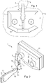
- the figures 1 and 2 illustrate an opening and closing device 1, also called a lock, of an article of leather goods 2, here a bag visible only schematically and partially.
- the leather goods article 2 comprises a body 3, a flap 4 attached by a first end (not shown) to the body 3, a hasp 5 fixed to a second end 6 of the flap 4, opposite the first end.
- the lock 1 comprises a lock housing 10 fixed to the body 3 and configured to receive and immobilize the hasp 5 in a locked configuration of a mechanism 11 (visible figure 5 ) of this housing 10, and to release the hasp 5 in an unlocked configuration of the mechanism 11 by means of an actuating button 7 of the lock 1.
- the lock 1 here also comprises a dummy button 9 mounted on the housing 10.
- the lock 1 further comprises a key 8 configured to move the mechanism 11 from one of its locked and unlocked configurations to the other (see below); so as to open and / or close item 2.
- the mechanism 11 for immobilizing / releasing the hasp 5 is actuated by introducing the key 8 into the housing 10 only by one or more translational movements of this key 8, without any rotational movement.
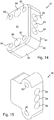
- the hasp 5 comprises a body 12 configured to be fixed to the second end 6 of the flap 4 of the body 3 of the article 2 and a head 13 projecting from an internal face 14 of the body 12, provided with an eye 15 and configured to be inserted into the lock housing 10 ( figures 2 and 3 ).
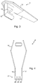
- the key 8 is here flat and provided with a gripping portion 16 and an insertion portion 17 connected to the gripping portion 16 ( figures 2 and 4 ).
- the insertion portion 17 has two opposite faces 18 and 19 and three predetermined security imprints 20 made on each of the faces 18 and 19 at a free end 21 of the key 8.
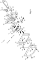
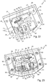
- the figure 5 illustrates the lock 1 in an exploded manner and the hasp 5, taken in isolation (that is to say without the bag 2).
- the lock housing 10 comprises a body (not shown) into which the so-called locking / unlocking mechanism 11 is introduced.
- the lock housing 10 is here of generally prismatic shape.
- the body of the housing 10 is formed of a palastre 22 and a cover 23 arranged facing the palastre 1 and fixed to the latter by means of first screws 27.
- the palastre 22 and the cover 23 are configured so as to provide a cavity 45 defining a predetermined space (not shown) in which the mechanism 11 is housed.
- the body of the housing 10 is also formed of a scratched plate 24 and a backing plate 25 which partially sandwich the cover 23.
- the scratched plate 24 and the backing plate 25 each have a window whose size and shape are substantially adapted to those of the cover 23, and are here fixed together on the palastre 22, by means of second screws 26 passing through orifices (not shown) provided in these plates 24 and 25.
- the backplate 25 has an external contour substantially equal to the external contour of the palastre 22, while the scratched plate 24 has an external contour slightly smaller than that of the backplate 25, so that the scratched plate 24 is at the less partially inserted into a recess 49 of the palastre 22.
- the scratched plate 24 is configured to be placed on an external face of the body 3 of the bag 2 while the backing plate 25 is configured to be placed on an internal face of this body 3; and that the second screws 26 are configured to provide a predetermined clearance between the backing plate 25 and the scratched plate 24 (visible figure 2 ), which play is blocked by the material thickness of the body 3 of the bag 2 when the housing 10 is fixed to this body 3.
- the actuation button 7 is generally formed of a gripping portion 28 and an actuating rod 29 which protrudes from the gripping portion 28 and which passes through the palastre 22.
- the mechanism 11 comprises a launching bolt 31 movably mounted in the housing 10 and configured to allow the closing of the bag 2 in the locked configuration of the mechanism 11 and the opening of the bag 2 in the unlocked configuration of the mechanism 11; as well as a bolt spring 32 making it possible to return the launching bolt 31 to a predetermined position when the latter is not subjected to an external stress, in particular by means of the actuating button 29.
- the launching bolt 31 is provided with a locking finger 48 configured to engage in the eye 15 of the head 13 of the hasp 5 in the locked configuration of the mechanism 11 and to disengage from this eye 15 in the unlocked configuration of the mechanism 11.
- the mechanism 11 further comprises a locking member 33, also called a star wheel, movably mounted in the housing 10 and configured to immobilize in the predetermined position the throwing bolt 31 in the locked configuration of the mechanism 11, and to allow movement of the bolt. throwing 31 into the unlocked configuration of mechanism 11; as well as a stop support 34 fixedly mounted in the housing 10 and on which the star wheel 32 is rotatably mounted, a first stop 35 and a stop spring 36 mounted at least partially on the stop support 34 and configured to act on the star wheel 33.
- a locking member 33 also called a star wheel
- the mechanism 11 further comprises a control system 30 mounted in the housing 10 and configured to cooperate with the key 8.
- the system 30 is provided with a movable part 37, also called a slide, and a fixed part 38, also called a piston support, configured to immobilize the slide 37 when the key 8 is remote from the system 30.
- the slide 37 is for its part configured to be driven by the key 8 during at least part of its translation in the housing 10 and to move the star wheel 33 to a first position in which the latter leaves the launching bolt 31 free. , the mechanism 11 then being in its unlocked configuration; and / or to a second position in which the star wheel 33 immobilizes the throwing bolt 31, the mechanism 11 then being in its locked configuration.
- the system 30 also includes slide springs 39 configured to return the slide 37 to an initial position in the absence of external stress, in particular by means of the key 8.
- the system 30 also comprises safety pivots 40 mounted movably in the slide 37 and configured to cooperate with the predetermined security imprints 20 of the key 8, second stops 41 mounted movably at least partially in the piston support 38 and piston springs 42 mounted in the piston support 38; the system 30 being configured so that the second stops 41 are interposed between the piston springs 42 and the pivots 40.
- the mechanism 11 further comprises a hasp spring 43 fixed in the housing 10 by means of a third screw 44 passing through an eyecup (not shown) formed in the hasp spring 43.
- This hasp spring 43 is configured to bear against the head 13 of the hasp 5 when the latter is immobilized in the housing 10 and to eject it from the housing 10 when it is released by the mechanism 11.
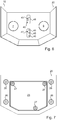
- the figures 6 and 7 show the assembled lock housing 10, respectively in front view and rear view.
- the locking finger 48 is visible through a second insertion slot 46 made in the palastro 22; while the free end of the pivots 40 is visible through a first insertion slot 47 also provided in the palastro 22.
- the backplate 25 is fixed to the palastre 22 by means of the second screws 26 and the cover 23 is disposed flush with the window formed in the backplate 25 and is fixed to the housing 22 by means of the first screws 27.
- the body 3 of the bag 2 here needs to be perforated for the cover 23 to pass through the material of this body 3.
- the palastre 22 also has its first and second insertion slots, respectively 47 and 46, a third insertion slot 50 of oblong shape and configured to slidably receive the rod 29 of the actuating button 7; as well as a circular hole 51 configured to integrally receive a rod (not shown) of the dummy button 9.
- the palastre 22 is further provided with an internal and closed side wall 52 which projects from an internal face 53 and which defines the cavity 45, the peripheral contour of which is substantially similar to the external contour of the cover 23.
- the palastre 22 comprises a plurality of positioning studs 54 configured to position the stop support 34, the slide 37 and the piston support 38, a guide block 55 configured to position and guide in translation the launching bolt 31, as well as a block U-shaped stopper 56 configured to position the throwing bolt 31 and form a stopper for the bolt spring 32.
- the cavity 45 has a first bottom wall 57 from which protrude two positioning studs 54 for the stop support 34, the guide block 55 and the U-shaped block 56; as well as a second bottom wall 58 formed in a recess with respect to the first bottom wall 57 and from which project four other positioning studs 54 for the slideway and two other positioning studs 54 for the piston support 38.
- the palastre also has a groove 88 formed in the second bottom wall 58.
- the internal and closed side wall 52 is provided with three excess thickness portions in which are formed screw holes 59 configured to receive the first screws 27 for fixing the cover 23.
- the palastre 22 is further provided with four screw channels 60 which protrude from the internal face 53 and which are configured to receive the second screws 26 for fixing the scratched plate 24 and the counter-plate 25.
- the cover 23 has a body having a first recess 63 in the shape of a cross configured to receive the hasp spring 43, an outer side wall 61 in which is formed an orifice 62 for passage of the third screw 44, which opens into the first recess 63 and which is extended by a fixing orifice 64 made in the body, for fixing the hasp spring 43; as well as a second recess 65 having a first bottom 66 configured to house at least partially the stop support 34 and the star wheel 35, and a second bottom 67 formed in a recess with respect to the first bottom 35 and configured to house at least partially the slide 37.
- the cover 23 further comprises two blind holes 68 (only one of which is completely visible) formed in the second bottom 67 and configured to each receive a respective slide spring 39; as well as three orifices 69 for passage of the first screws 27, configured to be opposite the screwing wells 59, for fixing the cover 23 on the palastre 22.
- the throwing bolt 31 ( figures 11 and 12 ) has the general shape of L, having a first branch 70, called vertical, in which is formed an orifice 71 configured to receive the end of the rod 29 of the actuating button 7; and a second branch 72, said horizontal, in which is formed a window 73 configured to receive on the one hand the U-shaped block 56 of the palastre 22 and on the other hand the bolt spring 32, which is interposed between a wall of the block in U 56 and an internal wall 75 bordering the window 73.
- the locking finger 48 of the throwing bolt 31 projects into the window 73 and the throwing bolt 31 also has a notch 74 extending the window 73 and configured to receive the guide block 55 of the palastre 22; two concavities 76 formed at the ends of the second branch 72 and provided for the passage of two screw holes 59 of the palastre 22, as well as a bearing face 77 formed on the first branch 70.
- Slide 37 ( figures 13 and 14 ) is formed by a body having a generally annular shape, with a central slot 78 for receiving the key 8.
- the body of the slide 37 has a side wall 79, a front wall 80 connected to the side wall 79 and a bottom wall 81 connected to the side wall 79 and opposite to the front wall 80.
- the central slot 78 opens only into the front wall 80.
- the slideway 37 has four through orifices 82 opening both in the front face 80 and in the bottom face 81 and configured to be traversed by four respective positioning studs 54 of the palastre 22.
- the slide 37 further comprises a drive notch 83 projecting from the front face 80 and from the side wall 79 and configured to move the star wheel 33; as well as a groove 84 projecting from the front wall 80 and configured to be housed in the groove 88 of the palastre 22.
- the slide 37 comprises three conduits 85 formed in the body and opening at a first end on an internal face 87 in the central slot 78 and at a second end opposite the first end in the side wall 79.
- the slide 37 has two blind holes 86 formed in the bottom face 81 and configured to receive the slide springs 39.
- Piston support 38 ( figure 15 ) is formed of a body in which are formed three receiving holes 89 configured to open out opposite the second ends of the conduits 85 of the slide 37; as well as two through orifices 90 configured to be crossed by two respective positioning studs 54 of the palastre 22.
- Every second stop 41 ( figure 16 ) has a generally cylindrical shape having a predetermined diameter allowing it to be moved both in a respective duct 85 of the slide 37 and in a respective receiving hole 89 of the piston support 38; a first end 91 configured to cooperate with a respective piston spring 42, which is mounted in the respective receiving hole 89, and a second end 92 configured to cooperate with a respective pivot 40.
- Each pivot 40 ( figure 17 ) has a base 93 having a predetermined diameter similar to that of the second stops 41 so as to be able to be moved in a respective duct 85 of the slide 37, as well as a head 94 connected to the base 93 by a shoulder 95 and of which the the free end 96 is tapered.
- Each assembly formed of a pivot 40 and a second stop 41 defines a piston (not shown).
- the piston springs 42 here have different and predetermined lengths, making it possible to provide each piston with a predetermined, similar or distinct stroke.
- impressions 20 of the key 8 and in particular their respective depth, are formed on the insertion portion 17 according to the predetermined strokes of the pistons; so as to form a combination making it possible to lock and unlock the mechanism 11.
- the stopper support 34 ( figure 18 ) is formed by a body having a first branch 100 and a second branch 101 extending substantially at right angles to the first branch 100.
- the stop support 34 is provided with a through hole 102 formed in the first branch 100 and opening onto a curved internal face 103 of this first branch 100; two through holes 104, one formed in the first branch 100 and the other in the second branch 101, which extend transversely to the through hole 102; and a journal 105 projecting from the second branch 101 and extending parallel to the curved internal face 103 and facing the through hole 102.
- the stop support 34 is furthermore provided with a concavity 106 formed at the end of the second branch 101 and provided for the passage of a screw hole 59 of the palastro 22.
- the first stop 35 ( figure 19 ) has a generally cylindrical shape having a predetermined diameter allowing it to be displaced in the through hole 102 of the stop support 34; a first end 98 configured to cooperate with the stop spring 36, which is partially mounted in the through hole 102, and a second end 99 configured to cooperate with the star wheel 33 under the effect of the stop spring 36.
- the star wheel 33 ( figures 20 and 21 ) comprises a base 107 having a generally parallelepipedal shape with four sides 108 and is provided with a central orifice 110 opening onto a lower wall 109 of the base 107.
- the star wheel 33 is rotatably mounted on the stop support 34 thanks to the journal 105 of the latter which is introduced into the central orifice 110 of the star wheel 33, the through hole 102 of the stop support 34 thus opening opposite one of the sides 108 of the star wheel 33.
- the base 107 of the star wheel 33 further comprises a non-return tooth 111 provided projecting on each side 108 and configured to cooperate with the drive notch 83 of the slide 37 so as to allow the rotation of the star wheel 33 only one way.
- each non-return tooth 111 has a ramp face 113 projecting from the respective side 108 and a straight face 112 joining the ramp face 113 and formed in the extension of the side immediately preceding the respective side from which the non-return tooth 111 protrudes.
- the base 107 of the star wheel 33 is further provided with a flange 114 opposite the lower wall 109 and from which protrudes a locking finger 115, formed here in two parts separated from each other by the central orifice. 110, and configured to come opposite the bearing face 75 of the throwing bolt 31.
- the locking process involves the steps below.
- the star wheel 33 is here in its first position in which its locking finger 115 is at a distance from the bearing face 77 of the throwing bolt 31 and extends in a plane substantially perpendicular to the plane defined on the surface of the palastre 22 ( referred to below as plan of the palace); so as to leave free the throwing bolt 31.
- the second stop 35 is biased by the stop spring 36 and thus bears against a side 108 of the star wheel 33.
- the hasp 5 (not visible on the figures 22 to 28 ) is introduced into the second insertion slot 46 made in the palastro 22, by a translational movement in a plane perpendicular to the plane of the palastro 22, until it comes into contact with the locking finger 48 of the throwing bolt 31.
- the hasp 5 is pressed against this finger 48 so as to move the throwing bolt 31 in translation in a plane substantially parallel to the plane of the palastre, against the bolt spring 32 to partially allow the head 13 of the hasp 5 to pass.
- the locking finger 48 is repositioned and engages in the eye 15 of the head 13 of the hasp 4 when the bolt spring 32 returns to its initial position and pushes the launching bolt 31 back.
- the key 8 is inserted by a first translational movement along a plane perpendicular to the plane of the palastre 22, into the first insertion slot 47 made in the palastre 22, then into the central slot 78 of the slide 37; until the indentations 20 of the key 8 come into contact with the conical ends 96 of the pivots 40 which protrude into the central slot 78.
- the first translational movement of the key 8 is continued so as to move the pistons formed by the pivots 40 and the second stops 41, against the piston springs 42, in a plane substantially parallel to the plane of the palastre 22.
- the pivots 40 push the second stops 41 until the latter are completely in the receiving holes 89 and out of the conduits 85, while the pivots remain completely in the conduits 85, thus allowing the slide 37 to move in the housing 10 under the action of a second translational movement of the key 8 (immediately succeeding and prolonging the first translational movement), always in a plane perpendicular to the plane of the palastro 22.
- the slide 37 thus released is moved in the cavity 45 of the housing 10, along a plane substantially perpendicular to the plane of the palastro 22, against the slide springs 20 by the second translational movement of the key 8.
- the notch 83 of the slide 37 comes into contact with the right face 112 of a non-return tooth 111 projecting from one side 108 of the star wheel 34 so as to drive the latter in rotation, here up to a quarter of turn, around the journal 105 of the stop support 34.
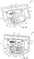
- the figures 24 and 25 illustrate the translation of the slide 37 and the rotation of the star wheel 34, here in a so-called intermediate configuration, where the star wheel 33 is turned by an eighth of a turn and where the pistons are split since the pivots 40 which are in the slide 37 are no longer opposite the second stops 41.
- the conduits 85 of the slide 37 are no longer facing the receiving holes 89 of the piston support 38.
- the slide 37 is moved until it comes into contact with the second bottom wall 58 of the palastre 22, where the groove 84 of the slide 37 is housed in the groove 88 of the palastre 22.
- the rotation of the star wheel 33 causes the displacement of its locking finger 115 from its first position where it leaves the throwing bolt 31 free to its second position where one of the parts of the locking finger 115 comes opposite and in close proximity, or even in contact with the bearing face 77 of the throwing bolt 31; so as to immobilize the latter in its predetermined position where its locking finger 48 is snapped into the eye 15 of the head 13 of the hasp 5.
- the bag 2 is thus closed.
- the key 8 is withdrawn from the slots 78 and 47 respectively of the slide 37 and of the palastre 22, by a translational movement (in a direction opposite to that of the translational movement for the insertion of the key 8).
- the slide 37 is thus returned to its initial position by the action of the slide springs 39 and, during the movement of the slide 37, the notch 83 comes into contact with the ramp face 113 of the non-return tooth 111 which protrudes from the side 108 facing the side wall 79 of the slide 37 and moves the star wheel 33.
- the profile of the ramp face 113 of the non-return tooth 111 allows the slide 37 not to return the star wheel 33 to its first position, and therefore allows the latter to remain in its second position where it locks the bolt. throwing 31.
- the unlocking process comprises the steps below.
- the star wheel 33 is here in its second position in which its locking finger 115 is opposite the bearing face 77 of the latch bolt 31.
- the key 8 is inserted by a first translational movement along a plane perpendicular to the plane of the palastre 22, in the first insertion slot 47 made in the palastre 22, then in the central slot 78 of the slide 37 ; until the indentations 20 of the key 8 come into contact with the conical ends 96 of the pivots 40 which protrude into the central slot 78.
- the first translational movement of the key 8 is continued so as to move the pistons formed by the pivots 40 and the second stops 41, against the piston springs 42, in a plane substantially parallel to the plane of the palastre 22.
- the pivots 40 push the second stops 41 until the latter are completely in the receiving holes 89 and out of the conduits 85, while the pivots 40 remain completely in the conduits 85, thus allowing the slide 37 to move in. the housing 10 under the action of a second translational movement of the key 8 (immediately succeeding and prolonging the first translational movement), still in a plane perpendicular to the plane of the palastre 22.
- the slide 37 thus released is moved in the cavity 45 of the housing 10, along a plane substantially perpendicular to the plane of the palastro 22, against the slide springs 20 by the second translational movement of the key 8.
- the notch 83 of the slide 37 comes into contact with the right face 112 of a non-return tooth 111 projecting from one side 108 of the star wheel 34 so as to drive the latter in rotation, here up to a quarter of turn, around the journal 105 of the stop support 34.
- the slide 37 is moved until it comes into contact with the second bottom wall 58 of the palastre 22, where the groove 84 of the slide 37 is housed in the groove 88 of the palastre 22.
- the rotation of the star wheel 33 causes the displacement of its locking finger 115 from its second position where it blocks the throwing bolt 31 in its first position where the locking finger 115 is at a distance from the bearing face 77 of the throwing bolt. 31 and therefore leaves him free.
- the key 8 is withdrawn from the slots 78 and 47 respectively of the slide 37 and of the palastre 22, by a translational movement (in a direction opposite to that of the translational movement for the insertion of the key 8).
- the slide 37 is thus returned to its initial position by the action of the slide springs 39 and, during the movement of the slide 37, the notch 83 comes into contact with the ramp face 113 of the non-return tooth 111 which protrudes from the side 108 facing the side wall 79 of the slide 37 and moves the star wheel 33.
- the profile of the ramp face 113 of the non-return tooth 111 allows the slide 37 not to return the star wheel 33 to its second position, and therefore allows the latter to remain in its first position where it leaves the throwing bolt 31 free.
- the actuator button 7 is actuated in a translational movement substantially parallel to the plane of the palastre 22, so as to move in translation the throwing bolt 31 against the bolt spring 32 which is compressed, by the action of the button 7 fixed by its rod 29 in the orifice 71 made on the first branch 70 of the latch bolt 31.
- the movement of the latch bolt 31 causes the withdrawal of its locking finger 48 from the eye 15 of the head 13 of the hasp 5, the latter being thus released from the housing 10 and ejected by the hasp spring 43.
- the button 7 is released and the throwing bolt 31 returns to its initial position under the action of the bolt spring 32 which returns it.
- the bag 2 is thus opened.
- the figures 29 to 31 illustrate a key 108 introduced into a control system 130 according to an alternative embodiment of the invention.
- the control system 130 is provided with a slide 137 movably mounted in a lock casing (not shown) and formed by a block 135 having a generally parallelepipedal shape (also called a movable part).
- the block 135 comprises a front flange 140, a rear flange 145 as well as a plurality of security elements 150 sandwiched between the front and rear flanges 140 and 145.
- the front and rear flanges 140 and 145 and the security elements are fixed together by fixing screws 136 so as to form the block 135.
- the front flange 140 comprises a drive notch 183 projecting from a peripheral edge of the front flange 140 and configured to drive a locking member of the launching bolt (not shown).
- the front flange 140 has an insertion slot 142 configured to receive the key 108 as well as a notch 143 formed in the peripheral edge of the front flange 140, opposite the drive notch 183.
- the front flange 140 further comprises two passage openings 141 for the passage of the fixing screws 136 as well as two blind holes 144 configured to receive slide springs (not shown).
- the rear flange 145 has an outer face 146 in which are formed two passage openings 147 for the passage of the fixing screws 136 as well as two through holes 186 for the passage of the slide springs.
- the rear flange 145 has a notch 148 formed in a peripheral edge of the rear flange 145.
- Each security element 150 is provided with a frame 151 having a peripheral slot 152 (part of which is hidden and therefore shown in dotted lines), two passage holes 153 for the passage of the fixing screws 136 and two through holes 154 for the passage of the slide springs.
- Each security element 150 is further provided with a recess 155 formed in the frame 151 and having the shape of a circle; an insertion slot 156 configured to receive the key 108 and a tooth 170 protruding into the recess 155.
- Each security element 150 comprises a movable member 157 housed in the recess 155 and mounted movably relative to the frame 151.
- the movable member 157 has a central window 158 for security and for receiving the key 108, central window 158 whose edges 159 are slightly bevelled, as well as a security groove 171 configured to be superimposed on the peripheral slot 152 of the device. frame 151.
- the safety groove 171 is formed in two parts, namely a first notch 172 formed in the movable member 157 and defining a recess 173, as well as a second notch 174 formed in the recess 173.
- the movable member 157 also has a cutout 175 here arranged opposite the safety groove 171 and defining a first wall 176 configured to bear against the tooth 170 of the frame 151, as well as a second wall 177 opposite. at the first wall 176.
- Each safety element 150 further comprises a safety spring 178 disposed in a space of the recess 155 left by the cutout 175 formed in the movable member 157, which safety spring 178 being interposed between and in abutment against the tooth 170 and the second wall 177.
- the control system 130 is further provided with a support 160 fixedly mounted in the lock housing (also called a fixed part) and formed by a substantially parallelepipedal body 161, provided with a positioning step 162 in the housing.
- the support has a plurality of locking teeth 163 which protrude from the body 161, in a direction opposite to the direction in which the step 162 extends, and which are configured to be inserted into the longitudinal groove 180 of the block 135.
- the movable members 157 of the security elements 150 are each in a rest position ( figure 31 ) where the peripheral slots 152 are at least partially closed by portions adjacent to the safety grooves 171 and more precisely here by a portion of the recess 173, so as to form obstacles in the groove 180 of the block 135 of the slide 137.
- each safety element 150 which rotates the respective movable member 157 so that the first wall 176 is in contact with or in close proximity to the tooth 170.
- the obstacles are substantially entangled with the teeth of the support 160 so that these teeth 160 prevent the translational movement of the slide 137.
- the key 8 When the key 8 is received and translated in the slide 137, the key 8 is inserted into the insertion slots 142 and 156 respectively of the front flange 140 and of the security elements 150 and in the central security windows 158 of the moving parts. 157 of these security elements 150, which align at least partially with the insertion slots 156; and rotate simultaneously the safety grooves 171 until the latter have their respective second notch 174 facing and superimposed on the peripheral slots 152.
- the locking member more generally comprises a base with at least three sides and the mechanism comprises a system for maintaining the locking member which is mounted on the stopper support and which is further configured to act on at least one of the sides of the locking member to hold it in any of its first position and its second position when not being driven by said movable part.
- the base of the locking member may also more generally have a generally parallelepipedal shape with at least four sides and be provided with a central orifice opening out on a lower wall of the base; while the stop support may be provided with a journal introduced into the central orifice and with at least one through hole facing at least one of the sides of the locking member.
- the mechanism may include at least a first stop and at least one stop spring mounted at least partially in a through hole and the first stop is configured to act on one of the sides of the locking member under the effect of the spring. stop.
Landscapes
- Physics & Mathematics (AREA)
- Electromagnetism (AREA)
- Lock And Its Accessories (AREA)
- Vehicle Step Arrangements And Article Storage (AREA)
Claims (14)
- Vorrichtung zum Öffnen und Schließen eines Artikels (2), insbesondere eines Lederwarenartikels, umfassend ein Schlossgehäuse (10) und einen Schlüssel (8; 108), der konfiguriert ist, um mit dem Schlossgehäuse (10) zusammenzuwirken, das mit einem Mechanismus (11) versehen ist, der eine verriegelte Konfiguration, in der der Artikel geschlossen werden kann, und eine entriegelte Konfiguration, in der der Artikel geöffnet werden kann, zulässt, wobei die Vorrichtung (1) konfiguriert ist, um den Mechanismus (11) von seiner verriegelten Konfiguration in seine entriegelte Konfiguration und umgekehrt ausschließlich durch Verschiebungsbewegungen des Schlüssels (8; 108) in dem Schlossgehäuse (10) zu überführen; wobei der Mechanismus (11) Folgendes umfasst:einen Fallenriegel (31), der beweglich im Schlossgehäuse angebracht ist und konfiguriert ist, um das Schließen des Artikels in der verrriegelten Konfiguration des Mechanismus und das Öffnen des Artikels in der entriegelten Konfiguration des Mechanismus zu ermöglichen;ein Sperrelement (33), das beweglich im Schlossgehäuse montiert ist und konfiguriert ist, um den Fallenriegel (31) in der verriegelten Konfiguration des Mechanismus in einer vorbestimmten Position zu arretieren und eine Bewegung des Fallenriegels (31) in der entriegelten Konfiguration des Mechanismus zuzulassen; undein Steuersystem (30; 130), das im Schlossgehäuse angebracht ist und konfiguriert ist, um mit dem Schlüssel (8; 108) zusammenzuwirken, wobei das System (30; 130) mit einem beweglichen Teil (37; 137) und einem feststehenden Teil (38; 160) versehen ist, der konfiguriert ist, um den beweglichen Teil zu arretieren, wenn der Schlüssel vom System entfernt ist, wobei der bewegliche Teil (37; 137) konfiguriert ist, um durch den Schlüssel während mindestens eines Teils seiner Verschiebung in dem Schlossgehäuse (10) angetrieben zu werden und das Sperrelement (33) in eine erste Position, in der dieses den Fallenriegel (31) freigibt, wobei sich der Mechanismus (11) dann in seiner entriegelten Konfiguration befindet, und/oder in eine zweite Position zu bewegen, in der dieses den Fallenriegel (31) arretiert, wobei sich der Mechanismus (11) dann in seiner verriegelten Konfiguration befindet;das Sperrelement (33) konfiguriert ist, um sich um sich selbst drehen zu können, und der bewegliche Teil (37; 137) des Steuersystems konfiguriert ist, um im Schlossgehäuse (10) verschoben werden zu können und eine Kerbe (83; 183) zum drehenden Antreiben des Sperrelements (33) aufweist;der Mechanismus (11) ferner einen Anschlagträger (34) aufweist, der fest im Schlossgehäuse (10) angebracht ist, und wobei das Sperrelement (33) drehbar am Anschlagträger (34) angebracht ist;dadurch gekennzeichnet dass das Sperrelement (33) eine Basis (107) mit mindestens drei Seiten (108) umfasst, wobei der Mechanismus (11) ein System zum Halten des Sperrelements (33) umfasst, das auf dem Anschlagträger (34) montiert ist und das ferner konfiguriert ist, um auf mindestens eine der Seiten (108) des Sperrelements zu wirken, um es in einer seiner ersten Position oder seiner zweiten Position zu halten, wenn es nicht durch den beweglichen Teil (37) angetrieben wird.
- Vorrichtung nach Anspruch 1, dadurch gekennzeichnet dass der Fallenriegel (31) eine Auflagefläche (77) aufweist und das Sperrelement (33) eine Basis (107) und mindestens einen Sperrfinger (115) umfasst, der von der Basis (107) vorsteht und konfiguriert ist, um der Auflagefläche (77) des Fallenriegels gegenüber zu liegen.
- Vorrichtung nach Anspruch 1, dadurch gekennzeichnet dass die Basis (107) des Sperrelements (33) eine allgemeine parallelepipedische Form mit mindestens vier Seiten (108) aufweist und mit einer zentralen Öffnung (110) versehen ist, die in eine untere Wand (109) der Basis (107) mündet, wobei der Anschlagträger (34) mit einem Stift (105), der in die zentrale Öffnung (110) eingeführt ist, und mit mindestens einem Durchgangsloch (102) versehen ist, das mindestens einer der Seiten (108) des Sperrelements (33) gegenüberliegt, wobei der Mechanismus (11) mindestens einen ersten Anschlag (35) und mindestens eine Anschlagfeder (36) umfasst, die zumindest teilweise in dem mindestens einen Durchgangsloch (102) angebracht ist, und der mindestens eine erste Anschlag (35) konfiguriert ist, um unter der Wirkung der mindestens einen Anschlagfeder (36) auf eine der Seiten (108) des Sperrelements zu wirken.
- Vorrichtung nach einem der Ansprüche 1 und 3, dadurch gekennzeichnet dass die Basis (107) des Sperrelements (33) einen Rückschlagzahn (111) aufweist, der von jeder Seite (108) vorsteht und konfiguriert ist, um mit der Kerbe (83; 183) des beweglichen Teils (37; 137) zusammenzuwirken, um eine Drehung des Sperrelements (33) in nur einer Richtung zu ermöglichen.
- Vorrichtung nach einem der Ansprüche 1 bis 4, dadurch gekennzeichnet dass das Schlossgehäuse (10) einen Schlosskasten (22) und eine an dem Schlosskasten (22) befestigte Abdeckung (23) umfasst, wobei der Schlosskasten und die Abdeckung konfiguriert sind, um einen Hohlraum (45) zu bilden, der einen vorbestimmten Raum definiert, in dem der Mechanismus (11) untergebracht ist.
- Vorrichtung nach Anspruch 5, dadurch gekennzeichnet dass der Schlosskasten (22) mit einem ersten Schlitz (47) zum Einführen des Schlüssels (8; 108), einem zweiten Schlitz (46) zum Einführen einer Schließe (5) des Artikels (2) und einem dritten Schlitz (50) zum Einführen eines Betätigungsknopfes (7) versehen ist, der konfiguriert ist, um den Fallenriegel (31) in die entriegelte Konfiguration des Mechanismus (11) zu bewegen, um die Schließe (5) freizugeben.
- Vorrichtung nach Anspruch 6, dadurch gekennzeichnet dass der Fallenriegel (31) einen Verriegelungsfinger (48) aufweist, der konfiguriert ist, um die Schließe (5) in der verriegelten Konfiguration des Mechanismus (11) zu arretieren.
- Vorrichtung nach einem der Ansprüche 4 und 5, dadurch gekennzeichnet dass der Mechanismus (11) eine Riegelfeder (32) aufweist, wobei der Fallenriegel (31) eine allgemeine L-Form aufweist, mit einem ersten Zweig (70), in dem ein Loch (71) vorgesehen ist, das konfiguriert ist, um eine Endstange (29) des Betätigungsknopfes (7) aufzunehmen, und einem zweiten Zweig (72), in dem ein Fenster (73) vorgesehen ist, das konfiguriert ist, um die Riegelfeder (32) aufzunehmen, die zwischen einer Innenwand (75) des Fallenriegels (31) und einem Anschlagblock (56) angeordnet ist, der in den Hohlraum (45) des Verschlussgehäuses (10) ragt.
- Vorrichtung nach einem der Ansprüche 1 bis 8, dadurch gekennzeichnet dass der bewegliche Teil (37) des Steuersystems (30) mit einem Schlitz (78) zur Aufnahme des Schlüssels (8) sowie mit Kanälen (85) versehen ist, die an einem ersten Ende in den Aufnahmeschlitz (78) münden, und der Schlüssel (8) ein freies Ende (21) aufweist, auf dem vorbestimmte Sicherheitsaufdrucke (20) ausgebildet sind, und das Steuersystem (30) Sicherheitszapfen (40) aufweist, die beweglich in den Kanälen (85) angebracht sind.
- Vorrichtung nach Anspruch 9, dadurch gekennzeichnet dass der feststehende Teil (38) des Steuersystems (30) mit Aufnahmelöchern (89) versehen ist, die in gegenüberliegende zweite Enden der Kanäle (85) des beweglichen Teils (37) münden, die ihren ersten Enden gegenüberliegen, und dass das Steuersystem (30) außerdem zweite Anschläge (41), die zumindest teilweise beweglich in den Aufnahmelöchern (89) angebracht sind, und Kolbenfedern (42), die in den Aufnahmelöchern (89) angebracht sind, umfasst.
- Vorrichtung nach Anspruch 10, dadurch gekennzeichnet dass, wenn sich der Schlüssel (8) außerhalb des Aufnahmeschlitzes (78) des beweglichen Teils (37) befindet, die Zapfen (40) der Wirkung der Kolbenfedern (42) durch die zweiten Anschläge (41) ausgesetzt sind, die zwischen den Kolbenfedern (42) und den Zapfen (40) angeordnet sind, und teilweise in den Aufnahmeschlitz (78) ragen, wobei die zweiten Anschläge (41) dann rittlings in den Kanälen (85) und in den Aufnahmelöchern (89) angeordnet sind, wodurch eine Bewegung des beweglichen Teils (37) verhindert wird; und wenn der Schlüssel (8) aufgenommen und im Aufnahmeschlitz (78) verschoben wird, der Schlüssel (8) mit den Zapfen (40) in Kontakt kommt und sie dann gegen die Kolbenfedern (42) drückt, wobei die Zapfen (40) die zweiten Anschläge (41) drücken, bis letztere vollständig in den Aufnahmelöchern (89) und aus den Kanälen (85) heraus sind, wodurch die Verschiebung des beweglichen Teils (37) im Schlossgehäuse (10) unter der Wirkung der Verschiebungsbewegung des Schlüssels (8) ermöglicht wird.
- Vorrichtung nach einem der Ansprüche 1 bis 8, dadurch gekennzeichnet dass der bewegliche Teil (137) mehrere Sicherheitselemente (150) umfasst, die so zusammengefügt sind, dass sie einen Block (135) mit einer im Allgemeinen parallelepipedischen Form und einer Längsnut (180) bilden, wobei jedes der Sicherheitselemente (150) mit einem Rahmen (151) mit einem Umfangsschlitz (152) und einem beweglichen Element (157) versehen ist, das in dem Rahmen (151) angebracht ist und ein zentrales Sicherheitsfenster (158) zur Aufnahme des Schlüssels (108) und eine Sicherheitsrille (171) aufweist; und der feste Teil (160) einen Körper (161) und mehrere Zähne (163) umfasst, die konfiguriert sind, um in die Nut (180) eingesetzt werden zu können.
- Vorrichtung nach Anspruch 12, dadurch gekennzeichnet dass, wenn sich der Schlüssel (108) außerhalb des beweglichen Teils (137) befindet, die beweglichen Elemente (157) der Sicherheitselemente (150) sich jeweils in einer Ruheposition befinden, in der die Umfangsschlitze (152) zumindest teilweise durch an die Sicherheitsrillen (171) angrenzende Abschnitte (173) verschlossen sind, wodurch Hindernisse in der Nut (180) des beweglichen Teils (137) gebildet werden, die die Zähne (163) des festen Teils (160) sperren und somit die Bewegung des beweglichen Teils (137) verhindern; und wenn der Schlüssel (108) in dem beweglichen Teil (137) aufgenommen und verschoben wird, der Schlüssel (108) in die zentralen Sicherheitsfenster (158) eingeführt wird und gleichzeitig die Sicherheitsrillen (171) schwenkt, bis diese den Umfangsschlitzen (152) zugewandt sind, wodurch die Nut (180) freigegeben wird und anschließend der bewegliche Teil (137) sich unter der Wirkung der Verschiebungsbewegung des Schlüssels (108) im Schlossgehäuse bewegen kann.
- Lederwarenartikel, umfassend einen Körper (3), eine Lasche (4), die mit einem ersten Ende an dem Körper (3) befestigt ist, eine Schließe (5), die an einem zweiten Ende (6) der Lasche (4) gegenüber dem ersten Ende befestigt ist, sowie eine Öffnungs- und Schließvorrichtung (1) nach einem der Ansprüche 1 bis 13, die am Körper (3) angebracht ist und konfiguriert ist, um die Schließe (5) in einer verriegelten Konfiguration eines Mechanismus (11) der Öffnungs- und Schließvorrichtung (1) aufzunehmen und sichern und die Schließe (5) in einer entriegelten Konfiguration des Mechanismus (11) freizugeben.
Applications Claiming Priority (1)
| Application Number | Priority Date | Filing Date | Title |
|---|---|---|---|
| FR1456049A FR3022939B1 (fr) | 2014-06-27 | 2014-06-27 | Dispositif d'ouverture et de fermeture d'un article notamment de maroquinerie et article comportant un tel dispositif |
Publications (2)
| Publication Number | Publication Date |
|---|---|
| EP2960406A1 EP2960406A1 (de) | 2015-12-30 |
| EP2960406B1 true EP2960406B1 (de) | 2020-10-21 |
Family
ID=51830432
Family Applications (1)
| Application Number | Title | Priority Date | Filing Date |
|---|---|---|---|
| EP15173490.2A Active EP2960406B1 (de) | 2014-06-27 | 2015-06-23 | Vorrichtung zum öffnen und schliessen eines artikels, insbesondere eines lederwaren-artikels, und artikel, der eine solche vorrichtung umfasst |
Country Status (3)
| Country | Link |
|---|---|
| EP (1) | EP2960406B1 (de) |
| CN (1) | CN105257116B (de) |
| FR (1) | FR3022939B1 (de) |
Families Citing this family (3)
| Publication number | Priority date | Publication date | Assignee | Title |
|---|---|---|---|---|
| FR3106474B1 (fr) * | 2020-01-24 | 2022-02-18 | Hermes Sellier | Article de maroquinerie du type bagage |
| FR3106476B1 (fr) * | 2020-01-24 | 2022-02-18 | Hermes Sellier | Article de maroquinerie du type bagage |
| GB2598321B (en) * | 2020-08-25 | 2023-05-17 | Henry Squire & Sons Holdings Ltd | A locking mechanism |
Family Cites Families (8)
| Publication number | Priority date | Publication date | Assignee | Title |
|---|---|---|---|---|
| FR898459A (fr) * | 1943-05-17 | 1945-04-24 | Serrure plate de sûreté | |
| FR1196802A (fr) * | 1956-03-12 | 1959-11-26 | Serrure | |
| CH378183A (fr) * | 1960-12-08 | 1964-05-31 | Albert Dreyfus Jean | Serrure et sa clé |
| US3640107A (en) * | 1969-09-24 | 1972-02-08 | Abraham Isaac Scherz | Key-controlled locks |
| NO166248C (no) * | 1988-05-24 | 1991-06-19 | Trioving As | Anordning ved omkodbar hullkortlaas. |
| CN2047697U (zh) * | 1989-03-27 | 1989-11-15 | 尤昌富 | 皮包扣 |
| US5212974A (en) | 1992-05-28 | 1993-05-25 | Shen Kou Chi | Card type locking apparatus |
| FR2692311B1 (fr) | 1992-06-15 | 1995-01-27 | Nguyen Quoc Binh | Commande mécanique autonome à clé miniaturisée intégrée à la surface d'une bague et qui fonctionne par simple contact extérieur avec le boîtier de commande. |
-
2014
- 2014-06-27 FR FR1456049A patent/FR3022939B1/fr active Active
-
2015
- 2015-06-23 EP EP15173490.2A patent/EP2960406B1/de active Active
- 2015-06-26 CN CN201510364665.5A patent/CN105257116B/zh active Active
Non-Patent Citations (1)
| Title |
|---|
| None * |
Also Published As
| Publication number | Publication date |
|---|---|
| FR3022939B1 (fr) | 2018-08-24 |
| FR3022939A1 (fr) | 2016-01-01 |
| CN105257116A (zh) | 2016-01-20 |
| EP2960406A1 (de) | 2015-12-30 |
| CN105257116B (zh) | 2019-03-29 |
Similar Documents
| Publication | Publication Date | Title |
|---|---|---|
| EP0963498B2 (de) | Verschlussvorrichtung für eine tür | |
| FR3015952A1 (fr) | Systeme de verrouillage de capots | |
| EP3756501A1 (de) | Befestigungsvorrichtung für armband | |
| EP2960406B1 (de) | Vorrichtung zum öffnen und schliessen eines artikels, insbesondere eines lederwaren-artikels, und artikel, der eine solche vorrichtung umfasst | |
| EP3864240B1 (de) | Griffanordnung zum öffnen von fenster- oder türflügeln | |
| EP0801193B1 (de) | Einsteckschloss | |
| FR3047265A1 (fr) | Serrure d'ouvrant a embase elastiquement emboitable | |
| EP3725181B1 (de) | Vorrichtung zum öffnen und schliessen eines artikels, insbesondere eines lederwaren-artikels, und artikel, der eine solche vorrichtung umfasst | |
| EP2760703B1 (de) | Vorrichtung zur befestigung eines kraftfahrzeugdachbalkens und anordnung für in verschiedenen konfigurationen montierte dachbalken mit einer solchen vorrichtung | |
| EP1561888B1 (de) | Hauptgehäuse eines Treibstangenschlosses mit einem Treibstangenanschlag | |
| EP2909400B1 (de) | Bolzenbefestigungsvorrichtung für eine kraftfahrzeugtür und kraftfahrzeug mit solch einer befestigungsvorrichtung | |
| EP2586938B1 (de) | Verriegelungsvorrichtung für ein Öffnungselement | |
| FR2933243A1 (fr) | Dispositif d'obturation pour prise de courant. | |
| EP3282204B1 (de) | Verbindungssystem von anschlussstücken von zwei klimatisierungseinheiten mit irreversibler verriegelungsposition | |
| EP2320012B1 (de) | Verschluss für die Klappe eines Kastens | |
| FR2982305A1 (fr) | Verrou pour un premier vantail d'un systeme a double vantail | |
| FR3007056A1 (fr) | Dispositif de fermeture provisoire d'un element ouvrant sur un element support | |
| FR3019578A1 (fr) | Ferrure pour cadre profile comprenant une fixation elastique et coulissante | |
| FR2693297A1 (fr) | Dispositif de consignation et chariot encastrable comportant un tel dispositif. | |
| FR2815067A1 (fr) | Cylindre de surete a barillet prioritaire | |
| BE1020632A3 (fr) | Dispositif de serrure auxiliaire independante. | |
| EP3530851A1 (de) | Verriegelungssystem für eine brandschutztür mit seitlicher verschiebung | |
| EP3596284A1 (de) | Vorrichtung zum aufhängen und/oder abhängen eines flügels, zugehöriger flügel und montageverfahren | |
| FR2850697A1 (fr) | Serrure et porte correspondante | |
| FR2758847A1 (fr) | Barillet de serrure a paillettes et goupilles |
Legal Events
| Date | Code | Title | Description |
|---|---|---|---|
| PUAI | Public reference made under article 153(3) epc to a published international application that has entered the european phase |
Free format text: ORIGINAL CODE: 0009012 |
|
| AK | Designated contracting states |
Kind code of ref document: A1 Designated state(s): AL AT BE BG CH CY CZ DE DK EE ES FI FR GB GR HR HU IE IS IT LI LT LU LV MC MK MT NL NO PL PT RO RS SE SI SK SM TR |
|
| AX | Request for extension of the european patent |
Extension state: BA ME |
|
| 17P | Request for examination filed |
Effective date: 20160203 |
|
| RBV | Designated contracting states (corrected) |
Designated state(s): AL AT BE BG CH CY CZ DE DK EE ES FI FR GB GR HR HU IE IS IT LI LT LU LV MC MK MT NL NO PL PT RO RS SE SI SK SM TR |
|
| GRAP | Despatch of communication of intention to grant a patent |
Free format text: ORIGINAL CODE: EPIDOSNIGR1 |
|
| STAA | Information on the status of an ep patent application or granted ep patent |
Free format text: STATUS: GRANT OF PATENT IS INTENDED |
|
| RIC1 | Information provided on ipc code assigned before grant |
Ipc: E05B 29/00 20060101ALI20191212BHEP Ipc: E05B 27/00 20060101AFI20191212BHEP |
|
| INTG | Intention to grant announced |
Effective date: 20200114 |
|
| GRAJ | Information related to disapproval of communication of intention to grant by the applicant or resumption of examination proceedings by the epo deleted |
Free format text: ORIGINAL CODE: EPIDOSDIGR1 |
|
| STAA | Information on the status of an ep patent application or granted ep patent |
Free format text: STATUS: REQUEST FOR EXAMINATION WAS MADE |
|
| GRAP | Despatch of communication of intention to grant a patent |
Free format text: ORIGINAL CODE: EPIDOSNIGR1 |
|
| STAA | Information on the status of an ep patent application or granted ep patent |
Free format text: STATUS: GRANT OF PATENT IS INTENDED |
|
| INTC | Intention to grant announced (deleted) | ||
| INTG | Intention to grant announced |
Effective date: 20200602 |
|
| GRAS | Grant fee paid |
Free format text: ORIGINAL CODE: EPIDOSNIGR3 |
|
| GRAA | (expected) grant |
Free format text: ORIGINAL CODE: 0009210 |
|
| STAA | Information on the status of an ep patent application or granted ep patent |
Free format text: STATUS: THE PATENT HAS BEEN GRANTED |
|
| AK | Designated contracting states |
Kind code of ref document: B1 Designated state(s): AL AT BE BG CH CY CZ DE DK EE ES FI FR GB GR HR HU IE IS IT LI LT LU LV MC MK MT NL NO PL PT RO RS SE SI SK SM TR |
|
| REG | Reference to a national code |
Ref country code: GB Ref legal event code: FG4D Free format text: NOT ENGLISH |
|
| REG | Reference to a national code |
Ref country code: CH Ref legal event code: EP |
|
| REG | Reference to a national code |
Ref country code: DE Ref legal event code: R096 Ref document number: 602015060701 Country of ref document: DE |
|
| REG | Reference to a national code |
Ref country code: IE Ref legal event code: FG4D Free format text: LANGUAGE OF EP DOCUMENT: FRENCH |
|
| REG | Reference to a national code |
Ref country code: AT Ref legal event code: REF Ref document number: 1326013 Country of ref document: AT Kind code of ref document: T Effective date: 20201115 |
|
| REG | Reference to a national code |
Ref country code: AT Ref legal event code: MK05 Ref document number: 1326013 Country of ref document: AT Kind code of ref document: T Effective date: 20201021 |
|
| REG | Reference to a national code |
Ref country code: NL Ref legal event code: MP Effective date: 20201021 |
|
| PG25 | Lapsed in a contracting state [announced via postgrant information from national office to epo] |
Ref country code: GR Free format text: LAPSE BECAUSE OF FAILURE TO SUBMIT A TRANSLATION OF THE DESCRIPTION OR TO PAY THE FEE WITHIN THE PRESCRIBED TIME-LIMIT Effective date: 20210122 Ref country code: RS Free format text: LAPSE BECAUSE OF FAILURE TO SUBMIT A TRANSLATION OF THE DESCRIPTION OR TO PAY THE FEE WITHIN THE PRESCRIBED TIME-LIMIT Effective date: 20201021 Ref country code: FI Free format text: LAPSE BECAUSE OF FAILURE TO SUBMIT A TRANSLATION OF THE DESCRIPTION OR TO PAY THE FEE WITHIN THE PRESCRIBED TIME-LIMIT Effective date: 20201021 Ref country code: PT Free format text: LAPSE BECAUSE OF FAILURE TO SUBMIT A TRANSLATION OF THE DESCRIPTION OR TO PAY THE FEE WITHIN THE PRESCRIBED TIME-LIMIT Effective date: 20210222 Ref country code: NL Free format text: LAPSE BECAUSE OF FAILURE TO SUBMIT A TRANSLATION OF THE DESCRIPTION OR TO PAY THE FEE WITHIN THE PRESCRIBED TIME-LIMIT Effective date: 20201021 Ref country code: NO Free format text: LAPSE BECAUSE OF FAILURE TO SUBMIT A TRANSLATION OF THE DESCRIPTION OR TO PAY THE FEE WITHIN THE PRESCRIBED TIME-LIMIT Effective date: 20210121 |
|
| REG | Reference to a national code |
Ref country code: LT Ref legal event code: MG4D |
|
| PG25 | Lapsed in a contracting state [announced via postgrant information from national office to epo] |
Ref country code: IS Free format text: LAPSE BECAUSE OF FAILURE TO SUBMIT A TRANSLATION OF THE DESCRIPTION OR TO PAY THE FEE WITHIN THE PRESCRIBED TIME-LIMIT Effective date: 20210221 Ref country code: PL Free format text: LAPSE BECAUSE OF FAILURE TO SUBMIT A TRANSLATION OF THE DESCRIPTION OR TO PAY THE FEE WITHIN THE PRESCRIBED TIME-LIMIT Effective date: 20201021 Ref country code: LV Free format text: LAPSE BECAUSE OF FAILURE TO SUBMIT A TRANSLATION OF THE DESCRIPTION OR TO PAY THE FEE WITHIN THE PRESCRIBED TIME-LIMIT Effective date: 20201021 Ref country code: SE Free format text: LAPSE BECAUSE OF FAILURE TO SUBMIT A TRANSLATION OF THE DESCRIPTION OR TO PAY THE FEE WITHIN THE PRESCRIBED TIME-LIMIT Effective date: 20201021 Ref country code: BG Free format text: LAPSE BECAUSE OF FAILURE TO SUBMIT A TRANSLATION OF THE DESCRIPTION OR TO PAY THE FEE WITHIN THE PRESCRIBED TIME-LIMIT Effective date: 20210121 Ref country code: ES Free format text: LAPSE BECAUSE OF FAILURE TO SUBMIT A TRANSLATION OF THE DESCRIPTION OR TO PAY THE FEE WITHIN THE PRESCRIBED TIME-LIMIT Effective date: 20201021 Ref country code: AT Free format text: LAPSE BECAUSE OF FAILURE TO SUBMIT A TRANSLATION OF THE DESCRIPTION OR TO PAY THE FEE WITHIN THE PRESCRIBED TIME-LIMIT Effective date: 20201021 |
|
| PG25 | Lapsed in a contracting state [announced via postgrant information from national office to epo] |
Ref country code: HR Free format text: LAPSE BECAUSE OF FAILURE TO SUBMIT A TRANSLATION OF THE DESCRIPTION OR TO PAY THE FEE WITHIN THE PRESCRIBED TIME-LIMIT Effective date: 20201021 |
|
| REG | Reference to a national code |
Ref country code: DE Ref legal event code: R097 Ref document number: 602015060701 Country of ref document: DE |
|
| PG25 | Lapsed in a contracting state [announced via postgrant information from national office to epo] |
Ref country code: SK Free format text: LAPSE BECAUSE OF FAILURE TO SUBMIT A TRANSLATION OF THE DESCRIPTION OR TO PAY THE FEE WITHIN THE PRESCRIBED TIME-LIMIT Effective date: 20201021 Ref country code: RO Free format text: LAPSE BECAUSE OF FAILURE TO SUBMIT A TRANSLATION OF THE DESCRIPTION OR TO PAY THE FEE WITHIN THE PRESCRIBED TIME-LIMIT Effective date: 20201021 Ref country code: LT Free format text: LAPSE BECAUSE OF FAILURE TO SUBMIT A TRANSLATION OF THE DESCRIPTION OR TO PAY THE FEE WITHIN THE PRESCRIBED TIME-LIMIT Effective date: 20201021 Ref country code: EE Free format text: LAPSE BECAUSE OF FAILURE TO SUBMIT A TRANSLATION OF THE DESCRIPTION OR TO PAY THE FEE WITHIN THE PRESCRIBED TIME-LIMIT Effective date: 20201021 Ref country code: CZ Free format text: LAPSE BECAUSE OF FAILURE TO SUBMIT A TRANSLATION OF THE DESCRIPTION OR TO PAY THE FEE WITHIN THE PRESCRIBED TIME-LIMIT Effective date: 20201021 Ref country code: SM Free format text: LAPSE BECAUSE OF FAILURE TO SUBMIT A TRANSLATION OF THE DESCRIPTION OR TO PAY THE FEE WITHIN THE PRESCRIBED TIME-LIMIT Effective date: 20201021 |
|
| PLBE | No opposition filed within time limit |
Free format text: ORIGINAL CODE: 0009261 |
|
| STAA | Information on the status of an ep patent application or granted ep patent |
Free format text: STATUS: NO OPPOSITION FILED WITHIN TIME LIMIT |
|
| PG25 | Lapsed in a contracting state [announced via postgrant information from national office to epo] |
Ref country code: DK Free format text: LAPSE BECAUSE OF FAILURE TO SUBMIT A TRANSLATION OF THE DESCRIPTION OR TO PAY THE FEE WITHIN THE PRESCRIBED TIME-LIMIT Effective date: 20201021 |
|
| 26N | No opposition filed |
Effective date: 20210722 |
|
| PG25 | Lapsed in a contracting state [announced via postgrant information from national office to epo] |
Ref country code: AL Free format text: LAPSE BECAUSE OF FAILURE TO SUBMIT A TRANSLATION OF THE DESCRIPTION OR TO PAY THE FEE WITHIN THE PRESCRIBED TIME-LIMIT Effective date: 20201021 |
|
| PG25 | Lapsed in a contracting state [announced via postgrant information from national office to epo] |
Ref country code: SI Free format text: LAPSE BECAUSE OF FAILURE TO SUBMIT A TRANSLATION OF THE DESCRIPTION OR TO PAY THE FEE WITHIN THE PRESCRIBED TIME-LIMIT Effective date: 20201021 |
|
| PG25 | Lapsed in a contracting state [announced via postgrant information from national office to epo] |
Ref country code: MC Free format text: LAPSE BECAUSE OF FAILURE TO SUBMIT A TRANSLATION OF THE DESCRIPTION OR TO PAY THE FEE WITHIN THE PRESCRIBED TIME-LIMIT Effective date: 20201021 |
|
| REG | Reference to a national code |
Ref country code: CH Ref legal event code: PL |
|
| GBPC | Gb: european patent ceased through non-payment of renewal fee |
Effective date: 20210623 |
|
| REG | Reference to a national code |
Ref country code: BE Ref legal event code: MM Effective date: 20210630 |
|
| PG25 | Lapsed in a contracting state [announced via postgrant information from national office to epo] |
Ref country code: LU Free format text: LAPSE BECAUSE OF NON-PAYMENT OF DUE FEES Effective date: 20210623 |
|
| PG25 | Lapsed in a contracting state [announced via postgrant information from national office to epo] |
Ref country code: LI Free format text: LAPSE BECAUSE OF NON-PAYMENT OF DUE FEES Effective date: 20210630 Ref country code: IE Free format text: LAPSE BECAUSE OF NON-PAYMENT OF DUE FEES Effective date: 20210623 Ref country code: GB Free format text: LAPSE BECAUSE OF NON-PAYMENT OF DUE FEES Effective date: 20210623 Ref country code: CH Free format text: LAPSE BECAUSE OF NON-PAYMENT OF DUE FEES Effective date: 20210630 |
|
| PG25 | Lapsed in a contracting state [announced via postgrant information from national office to epo] |
Ref country code: IS Free format text: LAPSE BECAUSE OF FAILURE TO SUBMIT A TRANSLATION OF THE DESCRIPTION OR TO PAY THE FEE WITHIN THE PRESCRIBED TIME-LIMIT Effective date: 20210221 |
|
| PG25 | Lapsed in a contracting state [announced via postgrant information from national office to epo] |
Ref country code: BE Free format text: LAPSE BECAUSE OF NON-PAYMENT OF DUE FEES Effective date: 20210630 |
|
| PG25 | Lapsed in a contracting state [announced via postgrant information from national office to epo] |
Ref country code: HU Free format text: LAPSE BECAUSE OF FAILURE TO SUBMIT A TRANSLATION OF THE DESCRIPTION OR TO PAY THE FEE WITHIN THE PRESCRIBED TIME-LIMIT; INVALID AB INITIO Effective date: 20150623 |
|
| P01 | Opt-out of the competence of the unified patent court (upc) registered |
Effective date: 20230512 |
|
| PG25 | Lapsed in a contracting state [announced via postgrant information from national office to epo] |
Ref country code: CY Free format text: LAPSE BECAUSE OF FAILURE TO SUBMIT A TRANSLATION OF THE DESCRIPTION OR TO PAY THE FEE WITHIN THE PRESCRIBED TIME-LIMIT Effective date: 20201021 |
|
| PGFP | Annual fee paid to national office [announced via postgrant information from national office to epo] |
Ref country code: IT Payment date: 20230911 Year of fee payment: 9 |
|
| PGFP | Annual fee paid to national office [announced via postgrant information from national office to epo] |
Ref country code: FR Payment date: 20230808 Year of fee payment: 9 Ref country code: DE Payment date: 20230810 Year of fee payment: 9 |
|
| PG25 | Lapsed in a contracting state [announced via postgrant information from national office to epo] |
Ref country code: MK Free format text: LAPSE BECAUSE OF FAILURE TO SUBMIT A TRANSLATION OF THE DESCRIPTION OR TO PAY THE FEE WITHIN THE PRESCRIBED TIME-LIMIT Effective date: 20201021 |