EP2752537A2 - Fitting device - Google Patents
Fitting device Download PDFInfo
- Publication number
- EP2752537A2 EP2752537A2 EP14150375.5A EP14150375A EP2752537A2 EP 2752537 A2 EP2752537 A2 EP 2752537A2 EP 14150375 A EP14150375 A EP 14150375A EP 2752537 A2 EP2752537 A2 EP 2752537A2
- Authority
- EP
- European Patent Office
- Prior art keywords
- fitting
- handle
- bearing ring
- gear
- rack
- Prior art date
- Legal status (The legal status is an assumption and is not a legal conclusion. Google has not performed a legal analysis and makes no representation as to the accuracy of the status listed.)
- Withdrawn
Links
Images


Classifications
-
- E—FIXED CONSTRUCTIONS
- E05—LOCKS; KEYS; WINDOW OR DOOR FITTINGS; SAFES
- E05B—LOCKS; ACCESSORIES THEREFOR; HANDCUFFS
- E05B13/00—Devices preventing the key or the handle or both from being used
- E05B13/002—Devices preventing the key or the handle or both from being used locking the handle
- E05B13/004—Devices preventing the key or the handle or both from being used locking the handle by locking the spindle, follower, or the like
-
- E—FIXED CONSTRUCTIONS
- E05—LOCKS; KEYS; WINDOW OR DOOR FITTINGS; SAFES
- E05B—LOCKS; ACCESSORIES THEREFOR; HANDCUFFS
- E05B41/00—Locks with visible indication as to whether the lock is locked or unlocked
-
- E—FIXED CONSTRUCTIONS
- E05—LOCKS; KEYS; WINDOW OR DOOR FITTINGS; SAFES
- E05B—LOCKS; ACCESSORIES THEREFOR; HANDCUFFS
- E05B63/00—Locks or fastenings with special structural characteristics
- E05B63/16—Locks or fastenings with special structural characteristics with the handles on opposite sides moving independently
-
- E—FIXED CONSTRUCTIONS
- E05—LOCKS; KEYS; WINDOW OR DOOR FITTINGS; SAFES
- E05B—LOCKS; ACCESSORIES THEREFOR; HANDCUFFS
- E05B1/00—Knobs or handles for wings; Knobs, handles, or press buttons for locks or latches on wings
- E05B2001/0076—The handle having at least two operating positions, e.g. the bolt can be retracted by moving the handle either upwards or downwards
-
- E—FIXED CONSTRUCTIONS
- E05—LOCKS; KEYS; WINDOW OR DOOR FITTINGS; SAFES
- E05B—LOCKS; ACCESSORIES THEREFOR; HANDCUFFS
- E05B65/00—Locks or fastenings for special use
- E05B65/0035—Locks or fastenings for special use for privacy rooms, e.g. bathrooms
- E05B2065/0039—Locks or fastenings for special use for privacy rooms, e.g. bathrooms with emergency release
Abstract
Description
Die vorliegende Erfindung betrifft eine Beschlaganordnung mit einem ersten und einem zweiten Beschlagelement zur Anordnung auf gegenüberliegenden Seiten eines Türblatts oder eines Fensterflügels, wobei dem ersten Beschlagelement eine erste Handhabe und dem zweiten Beschlagelement eine zweite Handhabe zugeordnet ist und die erste und zweite Handhabe mittels eines Betätigungsstifts miteinander verbunden sind, durch welchen bei Betätigung einer der Handhaben in einer ersten Richtung eine Falle eines Schlosses betätigbar ist.The present invention relates to a fitting arrangement with a first and a second fitting element for arrangement on opposite sides of a door leaf or window sash, wherein the first fitting element a first handle and the second fitting element is associated with a second handle and the first and second handle by means of an actuating pin with each other are connected, through which a case of a lock is actuated upon actuation of the handle in a first direction.
Beschlaganordnungen dieser Art sind grundsätzlich bekannt und werden in einer Vielzahl verschiedener Varianten zum Öffnen und Schließen von Fenstern und Türen eingesetzt. Dabei dienen die Beschlagelemente dazu, den Betätigungsstift zu lagern und zugleich eine gefällige Abdeckung der Lagerung und des Betätigungsstifts zu schaffen.Fitting arrangements of this type are known in principle and are used in a variety of different variants for opening and closing windows and doors. The fitting elements are used to store the actuating pin and at the same time to create a pleasing cover of the bearing and the actuating pin.
Soll eine Tür im geschlossenen Zustand zusätzlich verriegelbar sein, wird üblicherweise ein Schloss mit einer Verriegelungsmechanik verwendet, aus welcher mittels eines Schlüssels oder eines fest installierten Betätigungselements ein Riegel ausgefahren werden kann, der die Tür im geschlossenen Zustand verriegelt.If a door in the closed state is additionally lockable, a lock with a locking mechanism is usually used, from which by means of a key or a permanently installed actuating element, a bolt can be extended, which locks the door in the closed state.
Weiterhin ist es bekannt, anstelle eines Schlüssels die an der Tür oder an dem Fenster angebrachten Handhaben zu verwenden, um die Tür oder das Fenster zu verriegeln. Beispielsweise ist es bekannt, eine Handhabe der Tür, welche die Tür durch eine Bewegung nach unten öffnet, dazu zu verwenden, die Tür durch eine Bewegung nach oben zu verriegeln. Durch die nach oben gerichtete Bewegung der Handhabe kann entweder ein Riegel ausgefahren werden oder es kann eine Schlossfalle derart blockiert werden, dass sich die Tür nicht mehr öffnen lässt.Furthermore, it is known to use, instead of a key, the handles attached to the door or to the window to lock the door or the window. For example, it is known a handle To use the door, which opens the door downwards, to lock the door by moving it upwards. By the upward movement of the handle either a bolt can be extended or it can be a lock latch blocked so that the door can not be opened.
Um eine solche Verriegelung mittels Handhaben zu realisieren, ist eine aufwändige Anpassung der Schlossmechanik derart notwendig, dass die nach oben gerichtete Bewegung der Handhaben zu einer Verriegelung führt. Alternativ muss eine zusätzliche Mechanik in dem Türblatt oder dem Fensterflügel angeordnet werden, die eine Betätigung der Falle im verriegelten Zustand verhindert.In order to realize such a locking by means of handling, a complex adaptation of the lock mechanism is necessary such that the upward movement of the handles leads to a lock. Alternatively, an additional mechanism in the door leaf or the window sash must be arranged, which prevents actuation of the latch in the locked state.
Bekannte Vorrichtungen, die eine Verriegelung einer Tür durch eine Bewegung der Handhabe gestatten, sind folglich aufwändig in der Ausführung und damit kostspielig. Zudem ist eine Nachrüstung solcher Vorrichtungen üblicherweise nicht möglich.Known devices, which allow a locking of a door by a movement of the handle, are therefore complicated to perform and thus expensive. In addition, retrofitting such devices is usually not possible.
Es ist eine der Erfindung zugrunde liegende Aufgabe, eine Beschlaganordnung zu schaffen, welche es ermöglicht, auf einfache Weise Fenster und Türen durch eine Bewegung einer Handhabe zu verriegeln. Weiterhin soll die Beschlaganordnung bei bestehenden Fenstern und Türen leicht nachrüstbar sein.It is an object underlying the invention to provide a fitting arrangement which makes it possible to easily lock windows and doors by a movement of a handle. Furthermore, the fitting arrangement should be easy to retrofit existing windows and doors.
Die Aufgabe wird durch eine Beschlaganordnung gemäß Anspruch 1 und insbesondere dadurch gelöst, dass sich ein Übertragungselement von dem ersten zu dem zweiten Beschlagelement erstreckt, durch welches bei einer Betätigung der ersten Handhabe in einer der ersten Richtung entgegengesetzten zweiten Richtung in dem zweiten Beschlagelement vorgesehene Verriegelungsmittel in eine Blockierstellung bewegbar sind, um eine Bewegung der zweiten Handhabe zu blockieren.The object is achieved by a fitting arrangement according to claim 1 and in particular by the fact that a transmission element extends from the first to the second fitting element, through which in an operation of the first handle in the second direction opposite direction provided in the second fitting element Locking means are movable to a blocking position to block a movement of the second handle.
Erfindungsgemäß wird zur Verriegelung keine speziell angepasste Schlossmechanik benötigt. Stattdessen sind in dem zweiten Beschlagelement Verriegelungsmittel vorgesehen, welche in ihrer Blockierstellung eine Bewegung der zweiten Handhabe verhindern. Die Verriegelungsmittel können durch eine Betätigung der ersten Handhabe in einer Richtung, die der Richtung zur Betätigung der Falle entgegengesetzt ist, in die Blockierstellung gebracht werden.According to the invention, no specially adapted lock mechanism is required for locking. Instead, locking means are provided in the second fitting element, which prevent a movement of the second handle in its blocking position. The locking means can be brought into the blocking position by an actuation of the first handle in a direction which is opposite to the direction for actuating the latch.
Durch die Einsparung einer zusätzlich in das Türblatt zu integrierenden Mechanik und des Umstands, dass keine spezielle Schlossmechanik vorgesehen werden muss, ist die erfindungsgemäße Beschlaganordnung einfach und damit kostengünstig herstellbar. Zudem sind die Verriegelungsmittel in das eine Beschlagelement integriert, d.h. es brauchen keine zusätzlichen Beschlagelemente und/oder Schlossdurchbrüche für die Verriegelungsmittel vorgesehen zu werden. Viele Türen und Fenster, die normale Standardschlösser aufweisen, lassen sich daher durch Austausch der Beschlagelemente auf einfache Weise nachträglich mit der erfindungsgemäßen Beschlaganordnung ausrüsten.By saving a additionally to be integrated into the door panel mechanism and the fact that no special lock mechanism must be provided, the fitting arrangement according to the invention is simple and therefore inexpensive to produce. In addition, the locking means are integrated into the one fitting element, i. there is no need to provide additional fitting elements and / or lock openings for the locking means. Many doors and windows that have normal standard locks can therefore be retrofitted by replacing the fitting elements in a simple manner with the fitting arrangement according to the invention.
Die erfindungsgemäße Beschlaganordnung, die allein durch die erste Handhabe verriegelt werden kann, eignet sich insbesondere für den Einsatz bei Türen mit geringeren Anforderungen an die Verriegelungssicherheit, wie z.B. Bad- oder Toilettentüren sowie Türen von Wohn- oder Büroräumen, bei denen eine Verriegelung nur von einer Seite her, nämlich von "innen" nötig ist. Soll also beispielsweise eine Toilettentür verriegelt werden, wird die Tür geschlossen und anschließend die innenliegende erste Handhabe nach oben bewegt. Die Bewegung der ersten Handhabe nach oben wird mittels des Übertragungselements an die Verriegelungsmittel übertragen, woraufhin die Verriegelungsmittel die zweite Handhabe blockieren, welche sich außerhalb der Toilette befindet. Die zweite Handhabe kann nun nicht mehr nach unten gedrückt werden, um die Toilettentür zu öffnen. Die Toilettentür ist folglich verriegelt.The fitting arrangement according to the invention, which can be locked only by the first handle, is particularly suitable for use in doors with lower requirements for locking security, such as bathroom or toilet doors and doors of living or office space, where a lock only from one Side, namely from "inside" is necessary. If, for example, a toilet door is to be locked, the door is closed and then the inner first handle is moved upwards. The movement of the first handle after above is transmitted by means of the transmission element to the locking means, whereupon the locking means block the second handle, which is located outside the toilet. The second handle can now no longer be pushed down to open the toilet door. The toilet door is thus locked.
Vorteilhafte Ausführungsformen der Erfindung sind in den Unteransprüchen, den Zeichnungen und der Beschreibung angegeben.Advantageous embodiments of the invention are set forth in the subclaims, the drawings and the description.
Gemäß einer Ausführungsform ist das Übertragungselement mittels eines Zahnradgetriebes mit der ersten Handhabe gekoppelt. Die Verwendung eines Zahnradgetriebes ist insofern vorteilhaft, als dass durch Zahnräder eine Drehbewegung der ersten Handhabe besonders einfach aufgenommen und übertragen werden kann.According to one embodiment, the transmission element is coupled by means of a gear transmission with the first handle. The use of a gear transmission is advantageous in that a rotational movement of the first handle can be particularly easily received and transmitted by gears.
Vorzugsweise umfasst das Übertragungselement eine Welle, die drehfest mit einem ersten Zahnrad, welches in dem ersten Beschlagelement angeordnet ist, und einem zweiten Zahnrad, welches in dem zweiten Beschlagelement angeordnet ist, verbunden ist. Die Drehbewegung der ersten Handhabe wird in dem ersten Beschlagelement in eine Drehbewegung des ersten Zahnrades umgesetzt. Durch die drehfest mit dem ersten Zahnrad verbundene Welle wird die Drehbewegung durch das Türblatt hindurch zu dem zweiten Beschlagelement und damit an das zweite Zahnrad übertragen. In dem zweiten Beschlagelement werden durch die Verdrehung des zweiten Zahnrades die Verriegelungsmittel in die Blockierstellung bewegt. Auf diese Weise sind die Verriegelungsmittel durch eine Drehbewegung der ersten Handhabe betätigbar.Preferably, the transmission element comprises a shaft which is non-rotatably connected to a first gear, which is arranged in the first fitting element, and a second gear, which is arranged in the second fitting element. The rotational movement of the first handle is converted into a rotational movement of the first gear in the first fitting element. By the rotatably connected to the first gear shaft, the rotational movement is transmitted through the door leaf to the second fitting element and thus to the second gear. In the second fitting element, the locking means are moved by the rotation of the second gear in the blocking position. In this way, the locking means are actuated by a rotational movement of the first handle.
Gemäß einer weiteren Ausführungsform ist in dem ersten Beschlagelement ein erster Lagerring angeordnet, welcher eine Zahnung aufweist, die durch eine Bewegung der ersten Handhabe in der zweiten Richtung mit dem ersten Zahnrad in Eingriff bringbar ist und eine Verdrehung des ersten Zahnrades bewirkt. Die Zahnung ist derart angeordnet, dass nur eine Bewegung der ersten Handhabe von einer Ruhelage aus in der zweiten Richtung, beispielsweise nach oben, das erste Zahnrad und damit die Verriegelungsmittel betätigt. Wird die erste Handhabe aus der Ruhelage in der ersten Richtung bewegt, beispielsweise also nach unten, so greift die Zahnung des ersten Lagerrings nicht in das erste Zahnrad ein. Eine Verriegelung ist durch eine Bewegung nach unten folglich nicht möglich.According to a further embodiment, a first bearing ring is arranged in the first fitting element, which has a toothing, the by a movement of the first handle in the second direction is engageable with the first gear and causes a rotation of the first gear. The toothing is arranged such that only a movement of the first handle from a rest position in the second direction, for example, upwards, the first gear and thus actuates the locking means. If the first handle is moved out of the rest position in the first direction, for example downwards, then the teeth of the first bearing ring do not engage in the first toothed wheel. A lock is therefore not possible by moving down.
Um den für die Verriegelung erforderlichen Drehsinn des Übertragungselements zu erreichen, kann ein drittes Zahnrad zwischen die Zahnung des ersten Lagerrings und das erste Zahnrad geschaltet sein. Das dritte Zahnrad kann dabei identisch zu dem ersten Zahnrad ausgebildet sein.In order to achieve the required rotation of the transmission element for locking, a third gear between the teeth of the first bearing ring and the first gear can be connected. The third gear may be formed identical to the first gear.
Gemäß einer besonders vorteilhaften Ausführungsform umfassen die Verriegelungsmittel eine Zahnstange sowie einen zweiten Lagerring des zweiten Beschlagelements. Bevorzugt weist der zweite Lagerring an seiner Außenseite eine Abflachung oder einen Fortsatz mit einem geraden Rand auf, die/der in einer Ruhelage der zweiten Handhabe parallel zu der Zahnstange orientiert ist. Die Zahnstange kann eine Zahnung aufweisen, die mit dem zweiten Zahnrad in Eingriff steht. Auf einer der Zahnung gegenüberliegenden Seite umfasst die Zahnstange bevorzugt einen ebenen Flächenabschnitt. Durch eine Drehung des zweiten Zahnrades ist die Zahnstange vorteilhafterweise so verschiebbar, dass der ebene Flächenabschnitt mit der Abflachung oder dem Fortsatz des zweiten Lagerrings in Eingriff gebracht wird, wodurch eine Drehbewegung des Lagerrings und somit auch eine Verdrehung der mit dem zweiten Lagerring gekoppelten zweiten Handhabe blockiert wird.According to a particularly advantageous embodiment, the locking means comprise a rack and a second bearing ring of the second fitting element. Preferably, the second bearing ring on its outer side a flattening or an extension with a straight edge, which is oriented in a rest position of the second handle parallel to the rack. The rack may have a toothing that engages with the second gear. On a toothing opposite side, the rack preferably comprises a flat surface portion. By a rotation of the second gear, the rack is advantageously displaced so that the flat surface portion is brought into engagement with the flattening or the extension of the second bearing ring, whereby a rotational movement of the bearing ring and thus blocks a rotation coupled to the second bearing ring second handle becomes.
Alternativ kann die Abflachung oder der Fortsatz an dem zweiten Lagerring auch entfallen, wenn die Zahnstange den zweiten Lagerring durch Klemmung blockiert.Alternatively, the flattening or extension on the second bearing ring can also be omitted if the rack locks the second bearing ring by clamping.
Gemäß einer weiteren Ausführungsform umfasst die Zahnstange einen Muldenabschnitt und einen Verriegelungsabschnitt. Der Verriegelungsabschnitt ist vorzugsweise durch den bereits erwähnten ebenen Flächenabschnitt gebildet, wohingegen der Muldenabschnitt beispielsweise durch eine teilkreisförmige Ausnehmung der Zahnstange gebildet sein kann, deren Radius vorteilhafterweise an den Außenradius des zweiten Lagerrings angepasst ist. Befindet sich der Muldenabschnitt im entriegelten Zustand in dem Bereich des zweiten Lagerrings, so ist eine Drehbewegung des Lagerrings und damit der zweiten Handhabe möglich. Wird hingegen die Zahnstange zur Verriegelung der Beschlaganordnung verschoben und der Verriegelungsabschnitt mit dem zweiten Lagerring in Kontakt gebracht, so sind der zweite Lagerring und die zweite Handhabe blockiert.According to a further embodiment, the rack comprises a trough portion and a locking portion. The locking portion is preferably formed by the already mentioned planar surface portion, whereas the trough portion may be formed for example by a part-circular recess of the rack, whose radius is advantageously adapted to the outer radius of the second bearing ring. Is the trough portion in the unlocked state in the region of the second bearing ring, a rotational movement of the bearing ring and thus the second handle is possible. If, however, the rack is moved to lock the fitting assembly and the locking portion brought into contact with the second bearing ring, the second bearing ring and the second handle are blocked.
Gemäß einer bevorzugten Ausführungsform umfasst die Zahnstange ein Anzeigeelement, welches signalisiert, dass die Beschlaganordnung verriegelt ist. Insbesondere bei Bad- und Toilettentüren ist es wünschenswert, dass von außen erkennbar ist, ob das Bad oder die Toilette besetzt ist. Durch das Vorsehen des Anzeigeelements an der Zahnstange wird die ohnehin benötigte Bewegung der Zahnstange auch dazu ausgenutzt, eine Verriegelung und damit eine Benutzung des Bads oder der Toilette anzuzeigen.According to a preferred embodiment, the rack comprises a display element which signals that the fitting arrangement is locked. Especially in bathroom and toilet doors, it is desirable that it is recognizable from the outside, whether the bathroom or toilet is occupied. By providing the display element on the rack, the already required movement of the rack is also utilized to indicate a lock and thus a use of the bathroom or the toilet.
Beispielsweise kann die Zahnstange zur Anzeige der Verriegelung, insbesondere seitlich, aus dem zweiten Beschlagelement herausschiebbar sein, so dass das Anzeigeelement nur dann sichtbar ist, wenn die Beschlaganordnung verriegelt ist. Beispielsweise kann dazu ein rot eingefärbter Teil der Zahnstange aus dem zweiten Beschlagelement herausgeschoben werden.For example, the rack to display the lock, in particular laterally be pushed out of the second fitting element, so that the display element is only visible when the fitting assembly is locked. For example, to a red-colored part the rack are pushed out of the second fitting element.
Alternativ oder zusätzlich können bzw. kann der erste und/oder der zweite Lagerring mit einem Anzeigeelement versehen sein, das signalisiert, dass die Beschlaganordnung verriegelt ist. Im verriegelten Zustand kann ein solches Anzeigeelement durch den ersten bzw. zweiten Lagerring in den Bereich eines Sichtfensters der Beschlaganordnung gebracht werden, um das Anzeigeelement sichtbar zu machen. Durch die Anordnung von Anzeigeelementen sowohl an dem ersten als auch an dem zweiten Lagerring kann der verriegelte Zustand auf beiden Seiten der Beschlaganordnung, d.h. sowohl auf der Türinnenseite als auch auf der Türaußenseite, angezeigt werden.Alternatively or additionally, the first and / or the second bearing ring can be provided with a display element which signals that the fitting arrangement is locked. In the locked state, such a display element can be brought by the first and second bearing ring in the region of a viewing window of the fitting assembly to make the display element visible. By arranging display elements on both the first and second bearing rings, the locked state on both sides of the fitting assembly, i. both on the inside of the door and on the outside of the door.
Der erste und/oder der zweite Lagerring können bzw. kann beispielsweise mit einem Anzeigering drehfest verbunden sein, an welchem das Anzeigeelement angebracht ist. Grundsätzlich kann das Anzeigeelement auch an einem eigenständigen Anzeigering angebracht sein, welcher insbesondere unabhängig von einem Lagerring verdrehbar ist.The first and / or the second bearing ring can, for example, be rotatably connected to a display ring to which the display element is attached. In principle, the display element can also be attached to an independent display ring, which in particular can be rotated independently of a bearing ring.
Gemäß einer vorteilhaften Ausführungsform verläuft der Betätigungsstift durch den ersten Lagerring hindurch, wobei der Lagerring nach innen ragende Nocken aufweist, die Anlageflächen und Freilaufbereiche für den Betätigungsstift definieren.According to an advantageous embodiment, the actuating pin extends through the first bearing ring, wherein the bearing ring has inwardly projecting cams, which define contact surfaces and free-wheeling areas for the actuating pin.
Weiter bevorzugt umfasst der Betätigungsstift einen drehfest mit der ersten Handhabe verbundenen ersten Stiftabschnitt und einen drehfest mit der zweiten Handhabe verbundenen zweiten Stiftabschnitt, wobei der erste und der zweite Stiftabschnitt gegeneinander verdrehbar sind. Dies trägt dazu bei, dass eine Bewegung des ersten Lagerrings in die zweite Richtung, d.h. eine Verriegelung der Beschlaganordnung, nur durch die erste Handhabe und nicht durch die zweite Handhabe bewirkt werden kann.More preferably, the actuating pin comprises a rotatably connected to the first handle first pin portion and a rotatably connected to the second handle second pin portion, wherein the first and the second pin portion against each other are rotatable. This contributes to a movement of the first bearing ring in the second direction, ie a locking of the fitting assembly, only by the first handle and not by the second handle can be effected.
Bevorzugt erstreckt sich der zweite Stiftabschnitt in den ersten Lagerring hinein, so dass er mit den Anlageflächen der Nocken in Eingriff bringbar ist. Die Nocken und die Freilaufbereiche des ersten Lagerrings sind bevorzugt derart ausgebildet, dass eine Bewegung der ersten Handhabe in der zweiten Richtung zwar zu einer Drehbewegung des ersten Lagerrings und somit zu einer Verriegelung der Beschlaganordnung führt, die Drehbewegung des ersten Lagerrings in der zweiten Richtung aufgrund der Freilauf-bereiche allerdings nicht an den zweiten Stiftabschnitt übertragen wird, da der zweite Stiftabschnitt in diesem Fall nicht mit den Anlageflächen der Nocken in Eingriff steht. Der zweite Stiftabschnitt bleibt während des Verriegelungsvorgangs somit in seiner Ruhelage.Preferably, the second pin portion extends into the first bearing ring, so that it can be brought into engagement with the contact surfaces of the cams. The cams and the freewheel areas of the first bearing ring are preferably designed such that a movement of the first handle in the second direction leads to a rotational movement of the first bearing ring and thus to a locking of the fitting arrangement, the rotational movement of the first bearing ring in the second direction due to However, freewheeling areas is not transmitted to the second pin portion, since the second pin portion is not engaged with the contact surfaces of the cam in this case. The second pin portion thus remains in its rest position during the locking operation.
Soll die Verriegelung der Beschlaganordnung wieder gelöst werden, so wird die erste Handhabe in der ersten Richtung bewegt und die Blockade des zweiten Lagerrings durch Zurückdrehen des ersten Zahnrades wieder gelöst. Während dessen überstreicht der zweite Stiftabschnitt wieder die Freilaufbereiche des ersten Lagerrings, ohne sich mitzudrehen, bis die Anlageflächen des ersten Lagerrings wieder an dem zweiten Stiftabschnitt zur Anlage kommen.If the locking of the fitting assembly to be released again, the first handle is moved in the first direction and the blockage of the second bearing ring by turning back the first gear again released. During this, the second pin section again sweeps over the freewheel areas of the first bearing ring, without turning, until the contact surfaces of the first bearing ring again come to rest against the second pin section.
Soll die Tür nicht nur entriegelt sondern auch geöffnet werden, wird die erste Handhabe weiter in der ersten Richtung gedreht. Da der zweite Stiftabschnitt nun mit den Anlageflächen der Nocken des ersten Lagerrings in Eingriff steht, wird die Drehbewegung der ersten Handhabe über den ersten Lagerring an den zweiten Stiftabschnitt übertragen, wodurch die Falle des Schlosses zurückgezogen wird, so dass sich die Tür öffnen lässt. Es versteht sich, dass sich die Tür im entriegelten Zustand auch durch eine entsprechende Betätigung der zweiten Handhabe öffnen lässt, da diese drehfest mit dem zweiten Stiftabschnitt verbunden ist.If the door is not only unlocked but also opened, the first handle is rotated further in the first direction. Since the second pin portion is now engaged with the abutment surfaces of the cams of the first bearing ring, the rotational movement of the first handle is transmitted via the first bearing ring to the second pin portion, whereby the latch of the lock is retracted so that the door can be opened. It is understood that the door in the unlocked state by a can open corresponding actuation of the second handle, since it is rotatably connected to the second pin portion.
Bevorzugt ist die erste Handhabe drehfest mit dem ersten Lagerring des ersten Beschlagelements und die zweite Handhabe drehfest mit dem zweiten Lagerring des zweiten Beschlagelements verbunden. Wird also der zweite Lagerring durch die Zahnstange blockiert, so lassen sich auch die zweite Handhabe und dadurch der zweite Stiftabschnitt nicht verdrehen und die Schlossfalle nicht zurückziehen.Preferably, the first handle is non-rotatably connected to the first bearing ring of the first fitting element and the second handle rotatably connected to the second bearing ring of the second fitting element. Thus, if the second bearing ring blocked by the rack, so can not twist the second handle and thereby the second pin section and not pull back the latch.
Die Erfindung wird im Folgenden beispielhaft anhand möglicher Ausführungsformen unter Bezugnahme auf die beigefügten Zeichnungen näher beschrieben. Es zeigen:
- Fig. 1
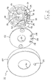
- eine Explosionsansicht einer ersten Ausführungsform eines ersten Beschlagelements;
- Fig. 2
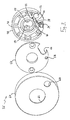
- eine Explosionsansicht einer ersten Ausführungsform eines zweiten Beschlagelements;
- Fig. 3
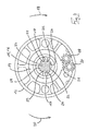
- eine Explosionsansicht einer zweiten Ausführungsform eines zweiten Beschlagelements;
- Fig. 4
- eine schematische Darstellung eines ersten Lagerrings in einer Ruhelage;
- Fig. 5
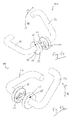
- eine erfindungsgemäße Beschlaganordnung in (a) einer ersten perspektivischen Ansicht und (b) einer zweiten perspektivischen Ansicht;
- Fig. 6
- eine schematische Darstellung einer zweiten Ausführungsform eines ersten Beschlagelements in (a) Ruhelage und (b) verriegeltem Zustand;
- Fig. 7
- eine schematische Darstellung einer dritten Ausführungsform eines zweiten Beschlagelements in Ruhelage (a) mit und (b) ohne Lagerring; und
- Fig. 8
- eine schematische Darstellung des Beschlagelements von
Fig. 7 im verriegelten Zustand (a) mit und (b) ohne Lagerring.
- Fig. 1
- an exploded view of a first embodiment of a first fitting element;
- Fig. 2
- an exploded view of a first embodiment of a second fitting element;
- Fig. 3
- an exploded view of a second embodiment of a second fitting element;
- Fig. 4
- a schematic representation of a first bearing ring in a rest position;
- Fig. 5
- a fitting arrangement according to the invention in (a) a first perspective view and (b) a second perspective view;
- Fig. 6
- a schematic representation of a second embodiment of a first fitting element in (a) rest position and (b) locked state;
- Fig. 7
- a schematic representation of a third embodiment of a second fitting element in rest position (a) with and (b) without bearing ring; and
- Fig. 8
- a schematic representation of the fitting element of
Fig. 7 in the locked state (a) with and (b) without bearing ring.
Das in
Das erste Beschlagelement 10 umfasst einen ersten Grundkörper 12, der ringförmig ausgebildet ist und in seinem Inneren einen ersten Lagerring 14 trägt. Der erste Lagerring 14 ist gegenüber dem ersten Grundkörper 12 drehbar gelagert und in
Durch den ersten Lagerring 14 hindurch verläuft ein Betätigungsstift 15, im vorliegenden Ausführungsbeispiel ein Vierkantstift, der nicht gezeigte erste und zweite Handhaben, z.B. Türgriffe, miteinander verbindet. Der Betätigungsstift 15 ist in zwei Stiftabschnitte unterteilt, die gegeneinander verdrehbar, in einer durch den Betätigungsstift definierten axialen Richtung aber fest miteinander verbunden sind.Through the
Ein nicht gezeigter erster Stiftabschnitt des Betätigungsstifts 15, an welchem die erste Handhabe drehfest befestigt ist, verläuft ausschließlich innerhalb des ersten Beschlagelements 10, während sich der zweite Stiftabschnitt 16 des Betätigungsstifts 15 von der zweiten Handhabe aus durch das zweite Beschlagelement 36 und durch die Tür hindurch zumindest teilweise bis in den ersten Lagerring 14 hinein erstreckt (
Der erste Lagerring 14 weist an seiner inneren Umfangsfläche zwei einander gegenüberliegende Vorsprünge 17 auf, die in einen Schlitz der ersten Handhabe eingreifen, um den ersten Lagerring 14 und die erste Handhabe durch Formschluss drehfest miteinander zu koppeln.The
Die in
Der erste Lagerring 14 umfasst an seiner inneren Umfangsfläche Nocken 22, die je nach Drehrichtung des ersten Lagerrings 14 mit dem zweiten Stiftabschnitt 16 in oder außer Eingriff bringbar sind.The
In der in
Wird die erste Handhabe ausgehend von der in
In einem Abschnitt einer äußeren Umfangsfläche des ersten Lagerrings 14 ist eine Zahnung 26 vorgesehen, welche durch die Verdrehung des ersten Lagerrings 14 aus der in
Die Drehbewegung des ersten Zahnrades 30 wird über die Welle 32 durch die Tür hindurch an ein zweites Zahnrad 34 übertragen, welches in einem zweiten Beschlagelement 36 angeordnet ist, das in
Das zweite Zahnrad 34 ist mit einer Zahnstange 38 verzahnt, die tangential zu dem zweiten Lagerring 46 verschiebbar an dem zweiten Grundkörper 48 gelagert und mittels zweier Führungsvorsprünge 39 des zweiten Grundkörpers 48 geführt ist.The
Die Zahnstange 38 weist an ihrer dem zweiten Lagerring 46 zugewandten Seite eine Mulde 42 auf, in welche der zweite Lagerring 46 im entriegelten Zustand der Beschlaganordnung eintauchen kann und welche dadurch eine Verdrehung des zweiten Lagerrings 46 gestattet.The
Benachbart zu der Mulde 42 weist die Zahnstange 38 einen ebenen Oberflächenabschnitt auf, der als Verriegelungsabschnitt 40 dient. Der Verriegelungsabschnitt 40 ist mit einer Abflachung 44 des zweiten Lagerrings 46 in Eingriff bringbar, um eine Verdrehung des zweiten Lagerrings 46 zu blockieren. Die Abflachung 44 des zweiten Lagerrings 46 ist dabei derart angeordnet, dass sie in einer Ruhelage der zweiten Handhabe parallel zu dem Verriegelungsabschnitt 40 der Zahnstange 38 verläuft, so dass eine Verriegelung also nur dann erfolgen kann, wenn sich die zweite Handhabe in ihrer Ruhelage befindet.Adjacent to the
Durch die Bewegung der ersten Handhabe in der zweiten Richtung 20 wird der Verrieglungsabschnitt 40 durch Verschiebung der Zahnstange 38 mit der Abflachung 44 in Eingriff gebracht, wodurch eine Drehung des zweiten Lagerrings 46 und damit der zweiten Handhabe und des zweiten Stiftabschnitts 16 des Betätigungsstifts 15 blockiert wird. In diesem verriegelten Zustand ist die Tür mittels der zweiten Handhabe also nicht zu öffnen. An dieser Stelle sei erwähnt, dass sich die Tür durch die zweite Handhabe auch nicht verriegeln lässt, weil eine Verdrehung der zweiten Handhabe zum Einen die Abflachung 44 des zweiten Lagerrings 46 verlagern und zum Anderen nicht zu der hierfür erforderlichen Verschiebung der Zahnstange 38 führen würde.By the movement of the first handle in the
Eine Entriegelung der Tür ist lediglich durch eine Bewegung der ersten Handhabe in der ersten Richtung 18 möglich, indem die Zahnstange 38 durch umgekehrte Bewegung der Zahnung 26 des ersten Lagerings 14 und entsprechende Rotation der Zahnräder 28, 30, 34 und der Welle 32 wieder in seine Ruhelage zurückgeschoben wird, so dass der zweite Lagerring 46 wieder in die Mulde 42 der Zahnstange 38 eintauchen kann und sich dadurch verdrehen lässt.An unlocking of the door is only possible by a movement of the first handle in the
Wie bereits erwähnt sind der zweite Lagerring 46, die Zahnstange 38 sowie das zweite Zahnrad 34 an dem zweiten Grundkörper 48 des zweiten Beschlagelements 36 beweglich gelagert. Der zweite Grundkörper 48 weist außerdem einen Ausschnitt 50 auf, durch welchen ein Anzeigeabschnitt 52 der Zahnstange 38 aus dem zweiten Beschlagelement 36 herausschiebbar ist. Der Anzeigeabschnitt 52 steht immer dann aus dem zweiten Beschlagelement 36 heraus, wenn der Verrieglungsabschnitt 40 mit der Abflachung 44 in Eingriff gebracht ist und somit eine Drehung des zweiten Lagerrings 46 blockiert ist.As already mentioned, the
Wie sich aus der Ausrichtung der ersten und zweiten Richtung 18, 20 erschließt, wird sich eine als Türgriff ausgebildete zweite Handhabe in der Darstellung von
Zur Schaffung einer drehfesten Kopplung zwischen dem zweiten Lagerring 46 und der zweiten Handhabe umfasst der zweite Lagerring 46 an seiner inneren Umfangsfläche zwei einander gegenüberliegende Vorsprünge 54, welche in einen Schlitz der Handhabe formschlüssig eingreifen. Somit ist bei einer Blockade des zweiten Lagerrings 46 durch die Zahnstange 38 sichergestellt, dass die zweite Handhabe und folglich auch der zweite Stiftabschnitt 16 des Betätigungsstifts 15 nicht bewegt werden können.To create a rotationally fixed coupling between the
Das erste Beschlagelement 10 und das zweite Beschlagelement 36 weisen jeweils eine Abdeckung 56 auf, die für beide Beschlagelemente 10, 36 identisch ausgeführt ist. Die Abdeckungen 56 tragen zur Lagerung der Zahnräder 28, 34, 30 bei und umfassen zu diesem Zweck entsprechende Bohrungen 58. Die Abdeckungen 56 sind symmetrisch ausgelegt, so dass sie für Beschlaganordnungen für rechts- und linksöffnende Türen und Fenster zu verwenden sind.The first
In
In
In
Der verriegelte Zustand wird jeweils in einem Anzeigefenster 68 des zweiten Beschlagelements 36 (
In einer Notöffnung 64 (
Das erste Beschlagelement 10 gemäß
Wird die Beschlaganordnung 70 von ihrem nicht verriegelten Zustand in den verriegelten Zustand gebracht, werden der erste Lagerring 14 und damit auch der erste Anzeigering 78 von der in
Die dritte Ausführungsform des zweiten Beschlagelements 36 unterscheidet sich von der Ausführungsform gemäß
Der zweite Anzeigering 84 ist um die Drehachse des Betätigungsstifts 15 herum drehbar gelagert und weist einen im Wesentlichen kreissektorförmigen Erweiterungsbereich 86 auf, der einen Winkelbereich von etwa 55° überdeckt. An dem Erweiterungsbereich 86 ist eine Verriegelungsanzeige 88 angebracht, die als kreisförmige farbige Fläche ausgebildet ist. Der Erweiterungsbereich 86 ist in einer Aussparung 90 geführt, die einen Anschlag für Rotationsbewegungen des Erweiterungsbereichs 86 bildet.The
Weiterhin unterscheidet sich die dritte Ausführungsform in der Ausgestaltung des zweiten Lagerrings 46 und der Zahnstange 38 von der Ausführungsform gemäß
Die Zahnstange 38 weist angrenzend an die Stufe 94 eine Mulde 42 auf, welche im nicht verriegelten Zustand eine Drehung des zweiten Lagerrings 46 gestattet (
Die Zahnstange 38 dieser Ausführungsform umfasst keinen Anzeigeabschnitt 52.The
Wird die Beschlaganordnung 70 aus ihrem nicht verriegelten Zustand (
Bei der Betätigung der Beschlaganordnung 70 werden Drehbewegungen der Handhaben 72, 74 in der ersten und der zweiten Richtung 18, 20 mittels der Vorsprünge 17, 54 formschlüssig an die Lagerringe 14, 46 übertragen. Die Form der ersten Handhabe 72 ist an den ersten Lagerring 14 und die der zweiten Handhabe 74 an den zweiten Lagerring 46 angepasst.Upon actuation of the
- 1010
- erstes Beschlagelementfirst fitting element
- 1212
- erster Grundkörperfirst basic body
- 1414
- erster Lagerringfirst bearing ring
- 1515
- Betätigungsstiftactuating pin
- 1616
- zweiter Stiftabschnittsecond pin section
- 1717
- Vorsprunghead Start
- 1818
- erste Richtungfirst direction
- 2020
- zweite Richtungsecond direction
- 2222
- Nockencam
- 2424
- FreilaufbereichFreewheel area
- 2626
- ZahnungPerforation
- 2828
- drittes Zahnradthird gear
- 3030
- erstes Zahnradfirst gear
- 3232
- Wellewave
- 3434
- zweites Zahnradsecond gear
- 3636
- zweites Beschlagelementsecond fitting element
- 3838
- Zahnstangerack
- 3939
- Führungsvorsprungguide projection
- 4040
- Verriegelungsabschnittlocking section
- 4242
- Muldetrough
- 4444
- Abflachungflattening
- 4646
- zweiter Lagerringsecond bearing ring
- 4848
- zweiter Grundkörpersecond basic body
- 5050
- Ausschnittneckline
- 5252
- Anzeigeabschnittdisplay section
- 5454
- Vorsprüngeprojections
- 5656
- Abdeckungcover
- 5858
- Bohrungdrilling
- 6060
- Abdeckkappecap
- 6262
- Durchgangpassage
- 6464
- NotöffnungEmergency opening
- 6666
- Führungsausschnittlead cut
- 6868
- Anzeigefensterdisplay window
- 7070
- Beschlaganordnungfitting assembly
- 7272
- erste Handhabefirst handle
- 7474
- zweite Handhabesecond handle
- 7676
- Schraubeneinsatzscrew insertion
- 7878
- erster Anzeigeringfirst indicator ring
- 8080
- Erweiterungsbereichextension area
- 8282
- Verriegelungsanzeigelock indicator
- 8484
- zweiter Anzeigeringsecond indicator ring
- 8585
- ZahnungPerforation
- 8686
- Erweiterungsbereichextension area
- 8888
- Verriegelungsanzeigelock indicator
- 9090
- Aussparungrecess
- 9292
- Fortsatzextension
- 9494
- Stufestep
Claims (14)
dadurch gekennzeichnet, dass
sich ein Übertragungselement (32) von dem ersten zu dem zweiten Beschlagelement (10, 36) erstreckt, durch welches bei einer Betätigung der ersten Handhabe (72) in einer der ersten Richtung (18) entgegengesetzten zweiten Richtung (20) in dem zweiten Beschlagelement (36) vorgesehene Verriegelungsmittel (38, 44, 94) in eine Blockierstellung bewegbar sind, um eine Bewegung der zweiten Handhabe (74) zu blockieren.A fitting assembly (70) having first and second fitting members (10, 36) for placement on opposite sides of a door panel or window sash, wherein the first fitting member (10) has a first handle (72) and the second bracket member (36) has a second handle (74) is associated with and the first and second handle (72, 74) are interconnected by means of an actuating pin (15) through which a latch of a lock is actuated upon actuation of one of the handles in a first direction (18),
characterized in that
a transmission element (32) extends from the first to the second fitting element (10, 36), by which upon actuation of the first handle (72) in a second direction (20) in the second fitting element (20) in a direction opposite to the first direction (18) 36) provided locking means (38, 44, 94) are movable in a blocking position to block a movement of the second handle (74).
dadurch gekennzeichnet, dass
das Übertragungselement (32) mittels eines Zahnradgetriebes mit der ersten Handhabe (72) gekoppelt ist.A fitting assembly (70) according to claim 1,
characterized in that
the transmission element (32) is coupled to the first handle (72) by means of a gear transmission.
dadurch gekennzeichnet, dass
das Übertragungselement eine Welle (32) umfasst, die drehfest mit einem ersten Zahnrad (30), welches in dem ersten Beschlagelement (10) angeordnet ist, und einem zweiten Zahnrad (34), welches in dem zweiten Beschlagelement (36) angeordnet ist, verbunden ist.A fitting assembly (70) according to claim 1 or 2,
characterized in that
the transmission element comprises a shaft (32) non-rotatably connected to a first gear (30) which is arranged in the first fitting element (10), and a second gear (34) which is arranged in the second fitting element (36) is.
dadurch gekennzeichnet, dass
in dem ersten Beschlagelement (10) ein erster Lagerring (14) angeordnet ist, welcher eine Zahnung (26) aufweist, die durch eine Bewegung der ersten Handhabe (72) in der zweiten Richtung (20) mit dem ersten Zahnrad (30) in Eingriff bringbar ist und eine Verdrehung des ersten Zahnrades (30) bewirkt.A fitting assembly (70) according to claim 3,
characterized in that
in the first fitting element (10) a first bearing ring (14) is arranged, which has a toothing (26) by a movement of the first handle (72) in the second direction (20) with the first gear (30) into engagement can be brought and causes a rotation of the first gear (30).
dadurch gekennzeichnet, dass
ein drittes Zahnrad (28) zwischen die Zahnung (26) des ersten Lagerrings (14) und das erste Zahnrad (30) geschaltet ist.Fitting arrangement (70) according to claim 4,
characterized in that
a third gear (28) is connected between the toothing (26) of the first bearing ring (14) and the first gear (30).
dadurch gekennzeichnet, dass
die Verriegelungsmittel eine Zahnstange (38) sowie einen zweiten Lagerring (46) des zweiten Beschlagelements (36) umfassen.A fitting arrangement (70) according to any one of the preceding claims,
characterized in that
the locking means comprise a rack (38) and a second bearing ring (46) of the second fitting element (36).
dadurch gekennzeichnet, dass
der zweite Lagerring (46) an seiner Außenseite eine Abflachung (44) oder einen Fortsatz (92) mit einer geraden Kante aufweist, die/der in einer Ruhelage der zweiten Handhabe (74) parallel zu der Zahnstange (38) orientiert ist.Fitting arrangement (70) according to claim 6,
characterized in that
the second bearing ring (46) has on its outer side a flattening (44) or an extension (92) with a straight edge, the / in a rest position of the second handle (74) is oriented parallel to the rack (38).
dadurch gekennzeichnet, dass
die Zahnstange (38) einen Muldenabschnitt (42) und einen Verriegelungsabschnitt (40, 94) umfasst.A fitting assembly (70) according to claim 6 or 7,
characterized in that
the rack (38) comprises a trough portion (42) and a locking portion (40, 94).
dadurch gekennzeichnet, dass
die Zahnstange (38) ein Anzeigeelement (52, 82, 88) umfasst, welches signalisiert, dass die Beschlaganordnung verriegelt ist.A fitting assembly (70) according to any one of claims 6 to 8,
characterized in that
the rack (38) comprises a display element (52, 82, 88) which signals that the fitting assembly is locked.
dadurch gekennzeichnet, dass
die Zahnstange (38) zur Anzeige der Verriegelung, insbesondere seitlich, aus dem zweiten Beschlagelement (36) herausschiebbar ist.A fitting assembly (70) according to any one of claims 6 to 9,
characterized in that
the rack (38) for displaying the lock, in particular laterally, from the second fitting element (36) can be pushed out.
dadurch gekennzeichnet, dass
der Betätigungsstift (15) durch den ersten Lagerring (14) hindurch verläuft, wobei der erste Lagerring (14) nach innen ragende Nocken (22) aufweist, die Anlageflächen und Freilaufbereiche (24) für den Betätigungsstift (15) definieren.A fitting arrangement (70) according to any one of the preceding claims,
characterized in that
the actuating pin (15) passes through the first bearing ring (14), the first bearing ring (14) having inwardly projecting cams (22) defining abutment surfaces and freewheeling regions (24) for the actuating pin (15).
dadurch gekennzeichnet, dass
der Betätigungsstift (15) einen mit der ersten Handhabe (72) drehfest verbundenen ersten Stiftabschnitt und einen mit der zweiten Handhabe (74) drehfest verbundenen zweiten Stiftabschnitt (16) umfasst, wobei der erste und der zweite Stiftabschnitt gegeneinander verdrehbar sind.A fitting arrangement (70) according to claim 11,
characterized in that
the actuating pin (15) has a first pin section connected in a rotationally fixed manner to the first handle (72) and a second pin section (16) connected in a rotationally fixed manner to the second handle (74) comprises, wherein the first and the second pin portion are rotated against each other.
dadurch gekennzeichnet, dass
sich der zweite Stiftabschnitt (16) in den ersten Lagerring (14) hineinerstreckt, so dass er mit dessen Nocken (22) in Eingriff bringbar ist.A fitting assembly (70) according to claim 12,
characterized in that
the second pin portion (16) extends into the first bearing ring (14) so as to be engageable with its cam (22).
dadurch gekennzeichnet, dass
die erste Handhabe (72) drehfest mit einem ersten Lagerring (14) des ersten Beschlagelements (10) und die zweite Handhabe (74) drehfest mit einem zweiten Lagerring (46) des zweiten Beschlagelements (36) verbunden ist.A fitting arrangement (70) according to any one of the preceding claims,
characterized in that
the first handle (72) rotatably connected to a first bearing ring (14) of the first fitting element (10) and the second handle (74) rotatably connected to a second bearing ring (46) of the second fitting element (36).
Applications Claiming Priority (1)
| Application Number | Priority Date | Filing Date | Title |
|---|---|---|---|
| DE201310200156 DE102013200156A1 (en) | 2013-01-08 | 2013-01-08 | fitting assembly |
Publications (1)
| Publication Number | Publication Date |
|---|---|
| EP2752537A2 true EP2752537A2 (en) | 2014-07-09 |
Family
ID=49943175
Family Applications (1)
| Application Number | Title | Priority Date | Filing Date |
|---|---|---|---|
| EP14150375.5A Withdrawn EP2752537A2 (en) | 2013-01-08 | 2014-01-07 | Fitting device |
Country Status (2)
| Country | Link |
|---|---|
| EP (1) | EP2752537A2 (en) |
| DE (1) | DE102013200156A1 (en) |
Cited By (3)
| Publication number | Priority date | Publication date | Assignee | Title |
|---|---|---|---|---|
| EP3388602A1 (en) * | 2017-04-12 | 2018-10-17 | ALSTOM Transport Technologies | Modular system for locking a door for access to a space, with reversible elements |
| EP3388603A1 (en) * | 2017-04-12 | 2018-10-17 | ALSTOM Transport Technologies | A system for locking a door for access to a space, in particular a toilet of a railway vehicle |
| EP3498941B1 (en) * | 2017-12-18 | 2023-06-07 | Hoppe Ag | Actuating handle with blocking device |
Family Cites Families (4)
| Publication number | Priority date | Publication date | Assignee | Title |
|---|---|---|---|---|
| US2006457A (en) * | 1931-08-29 | 1935-07-02 | Frederick E Hummel | Doorlock |
| JPH09203253A (en) * | 1996-01-30 | 1997-08-05 | Nagasawa Seisakusho:Kk | Door lock |
| JP3294219B2 (en) * | 1999-06-22 | 2002-06-24 | アトムリビンテック株式会社 | Door lock |
| JP4360507B2 (en) * | 2000-01-19 | 2009-11-11 | 吉郎 足立 | Door opening and closing device |
-
2013
- 2013-01-08 DE DE201310200156 patent/DE102013200156A1/en not_active Withdrawn
-
2014
- 2014-01-07 EP EP14150375.5A patent/EP2752537A2/en not_active Withdrawn
Non-Patent Citations (1)
| Title |
|---|
| None |
Cited By (5)
| Publication number | Priority date | Publication date | Assignee | Title |
|---|---|---|---|---|
| EP3388602A1 (en) * | 2017-04-12 | 2018-10-17 | ALSTOM Transport Technologies | Modular system for locking a door for access to a space, with reversible elements |
| EP3388603A1 (en) * | 2017-04-12 | 2018-10-17 | ALSTOM Transport Technologies | A system for locking a door for access to a space, in particular a toilet of a railway vehicle |
| FR3065245A1 (en) * | 2017-04-12 | 2018-10-19 | Alstom Transport Technologies | SYSTEM FOR LOCKING A ACCESS DOOR TO A SPACE, IN PARTICULAR THE TOILETS OF A RAILWAY VEHICLE |
| FR3065244A1 (en) * | 2017-04-12 | 2018-10-19 | Alstom Transport Technologies | MODULAR SYSTEM FOR LOCKING A ACCESS DOOR TO A SPACE, WITH REVERSIBLE ELEMENTS |
| EP3498941B1 (en) * | 2017-12-18 | 2023-06-07 | Hoppe Ag | Actuating handle with blocking device |
Also Published As
| Publication number | Publication date |
|---|---|
| DE102013200156A1 (en) | 2014-07-10 |
Similar Documents
| Publication | Publication Date | Title |
|---|---|---|
| DE3447748C2 (en) | ||
| EP2581531B1 (en) | Drive for an espagnolette of a window, door or similar item | |
| EP1932990A2 (en) | Locking device for doors, windows or similar, in particular an espagnolette lock with a panic function and multi-point locking | |
| EP1885977B1 (en) | Safety lock for a door, a gate or the like | |
| EP3309333B1 (en) | Arrangement with a blind frame for storing a wing frame | |
| EP0007395B1 (en) | Door lock with key-operated locking cylinder | |
| EP3266967B1 (en) | Bar lock | |
| EP2058461B1 (en) | Driving rod gear | |
| EP2796645B1 (en) | Bolt lock of a piece of furniture | |
| EP2107189B1 (en) | Coating for windows or doors | |
| EP2752537A2 (en) | Fitting device | |
| DE4114007C2 (en) | Espagnolette lock | |
| EP3266960B1 (en) | Arrangement with a blind frame for storing a wing frame | |
| EP3034719A1 (en) | Actuating device for a locking mechanism of a door or a window | |
| DE4244414C2 (en) | Lock for windows, doors and. the like | |
| EP0036141A1 (en) | Lock device for casement fastener, bar shutters and the like | |
| EP1671001B1 (en) | Lock | |
| DE102012012415A1 (en) | Locking device and thus equipped wings or wing system | |
| DE102010055397B4 (en) | Locking/unlocking device for a sliding door and door equipped with such a device | |
| EP0738814A1 (en) | Device on a door lock | |
| EP0367842B1 (en) | Handle assembly for doors, windows or the like | |
| WO2015176695A1 (en) | Panic lock device for an escape door of a sectional door or of a sectional lift and fold door | |
| EP0752509B1 (en) | Lockable handle for window, door or the like | |
| DE4200868A1 (en) | Lock for window or door - has two parallel bolts actuated by lock handle | |
| EP3655605B1 (en) | Lock |
Legal Events
| Date | Code | Title | Description |
|---|---|---|---|
| 17P | Request for examination filed |
Effective date: 20140107 |
|
| AK | Designated contracting states |
Kind code of ref document: A2 Designated state(s): AL AT BE BG CH CY CZ DE DK EE ES FI FR GB GR HR HU IE IS IT LI LT LU LV MC MK MT NL NO PL PT RO RS SE SI SK SM TR |
|
| AX | Request for extension of the european patent |
Extension state: BA ME |
|
| PUAI | Public reference made under article 153(3) epc to a published international application that has entered the european phase |
Free format text: ORIGINAL CODE: 0009012 |
|
| STAA | Information on the status of an ep patent application or granted ep patent |
Free format text: STATUS: THE APPLICATION IS DEEMED TO BE WITHDRAWN |
|
| 18D | Application deemed to be withdrawn |
Effective date: 20170801 |