EP2750187A1 - Semiconductor device and semiconductor device manufacturing method - Google Patents
Semiconductor device and semiconductor device manufacturing method Download PDFInfo
- Publication number
- EP2750187A1 EP2750187A1 EP12825504.9A EP12825504A EP2750187A1 EP 2750187 A1 EP2750187 A1 EP 2750187A1 EP 12825504 A EP12825504 A EP 12825504A EP 2750187 A1 EP2750187 A1 EP 2750187A1
- Authority
- EP
- European Patent Office
- Prior art keywords
- control terminal
- resin case
- resin
- opening
- insulating substrate
- Prior art date
- Legal status (The legal status is an assumption and is not a legal conclusion. Google has not performed a legal analysis and makes no representation as to the accuracy of the status listed.)
- Granted
Links
Images









Classifications
-
- H—ELECTRICITY
- H10—SEMICONDUCTOR DEVICES; ELECTRIC SOLID-STATE DEVICES NOT OTHERWISE PROVIDED FOR
- H10W—GENERIC PACKAGES, INTERCONNECTIONS, CONNECTORS OR OTHER CONSTRUCTIONAL DETAILS OF DEVICES COVERED BY CLASS H10
- H10W46/00—Marks applied to devices, e.g. for alignment or identification
-
- H—ELECTRICITY
- H05—ELECTRIC TECHNIQUES NOT OTHERWISE PROVIDED FOR
- H05K—PRINTED CIRCUITS; CASINGS OR CONSTRUCTIONAL DETAILS OF ELECTRIC APPARATUS; MANUFACTURE OF ASSEMBLAGES OF ELECTRICAL COMPONENTS
- H05K5/00—Casings, cabinets or drawers for electric apparatus
- H05K5/02—Details
- H05K5/0247—Electrical details of casings, e.g. terminals, passages for cables or wiring
-
- H—ELECTRICITY
- H10—SEMICONDUCTOR DEVICES; ELECTRIC SOLID-STATE DEVICES NOT OTHERWISE PROVIDED FOR
- H10D—INORGANIC ELECTRIC SEMICONDUCTOR DEVICES
- H10D12/00—Bipolar devices controlled by the field effect, e.g. insulated-gate bipolar transistors [IGBT]
- H10D12/01—Manufacture or treatment
-
- H—ELECTRICITY
- H10—SEMICONDUCTOR DEVICES; ELECTRIC SOLID-STATE DEVICES NOT OTHERWISE PROVIDED FOR
- H10W—GENERIC PACKAGES, INTERCONNECTIONS, CONNECTORS OR OTHER CONSTRUCTIONAL DETAILS OF DEVICES COVERED BY CLASS H10
- H10W40/00—Arrangements for thermal protection or thermal control
- H10W40/20—Arrangements for cooling
- H10W40/25—Arrangements for cooling characterised by their materials
- H10W40/255—Arrangements for cooling characterised by their materials having a laminate or multilayered structure, e.g. direct bond copper [DBC] ceramic substrates
-
- H—ELECTRICITY
- H10—SEMICONDUCTOR DEVICES; ELECTRIC SOLID-STATE DEVICES NOT OTHERWISE PROVIDED FOR
- H10W—GENERIC PACKAGES, INTERCONNECTIONS, CONNECTORS OR OTHER CONSTRUCTIONAL DETAILS OF DEVICES COVERED BY CLASS H10
- H10W70/00—Package substrates; Interposers; Redistribution layers [RDL]
- H10W70/60—Insulating or insulated package substrates; Interposers; Redistribution layers
- H10W70/67—Insulating or insulated package substrates; Interposers; Redistribution layers characterised by their insulating layers or insulating parts
- H10W70/69—Insulating materials thereof
- H10W70/698—Semiconductor materials that are electrically insulating, e.g. undoped silicon
-
- H—ELECTRICITY
- H10—SEMICONDUCTOR DEVICES; ELECTRIC SOLID-STATE DEVICES NOT OTHERWISE PROVIDED FOR
- H10W—GENERIC PACKAGES, INTERCONNECTIONS, CONNECTORS OR OTHER CONSTRUCTIONAL DETAILS OF DEVICES COVERED BY CLASS H10
- H10W74/00—Encapsulations, e.g. protective coatings
- H10W74/01—Manufacture or treatment
-
- H—ELECTRICITY
- H10—SEMICONDUCTOR DEVICES; ELECTRIC SOLID-STATE DEVICES NOT OTHERWISE PROVIDED FOR
- H10W—GENERIC PACKAGES, INTERCONNECTIONS, CONNECTORS OR OTHER CONSTRUCTIONAL DETAILS OF DEVICES COVERED BY CLASS H10
- H10W74/00—Encapsulations, e.g. protective coatings
- H10W74/10—Encapsulations, e.g. protective coatings characterised by their shape or disposition
- H10W74/111—Encapsulations, e.g. protective coatings characterised by their shape or disposition the semiconductor body being completely enclosed
- H10W74/114—Encapsulations, e.g. protective coatings characterised by their shape or disposition the semiconductor body being completely enclosed by a substrate and the encapsulations
-
- H—ELECTRICITY
- H10—SEMICONDUCTOR DEVICES; ELECTRIC SOLID-STATE DEVICES NOT OTHERWISE PROVIDED FOR
- H10W—GENERIC PACKAGES, INTERCONNECTIONS, CONNECTORS OR OTHER CONSTRUCTIONAL DETAILS OF DEVICES COVERED BY CLASS H10
- H10W74/00—Encapsulations, e.g. protective coatings
- H10W74/10—Encapsulations, e.g. protective coatings characterised by their shape or disposition
- H10W74/111—Encapsulations, e.g. protective coatings characterised by their shape or disposition the semiconductor body being completely enclosed
- H10W74/124—Encapsulations, e.g. protective coatings characterised by their shape or disposition the semiconductor body being completely enclosed the encapsulations having cavities other than that occupied by chips
-
- H—ELECTRICITY
- H10—SEMICONDUCTOR DEVICES; ELECTRIC SOLID-STATE DEVICES NOT OTHERWISE PROVIDED FOR
- H10W—GENERIC PACKAGES, INTERCONNECTIONS, CONNECTORS OR OTHER CONSTRUCTIONAL DETAILS OF DEVICES COVERED BY CLASS H10
- H10W74/00—Encapsulations, e.g. protective coatings
- H10W74/10—Encapsulations, e.g. protective coatings characterised by their shape or disposition
- H10W74/111—Encapsulations, e.g. protective coatings characterised by their shape or disposition the semiconductor body being completely enclosed
- H10W74/127—Encapsulations, e.g. protective coatings characterised by their shape or disposition the semiconductor body being completely enclosed characterised by arrangements for sealing or adhesion
-
- H—ELECTRICITY
- H10—SEMICONDUCTOR DEVICES; ELECTRIC SOLID-STATE DEVICES NOT OTHERWISE PROVIDED FOR
- H10W—GENERIC PACKAGES, INTERCONNECTIONS, CONNECTORS OR OTHER CONSTRUCTIONAL DETAILS OF DEVICES COVERED BY CLASS H10
- H10W74/00—Encapsulations, e.g. protective coatings
- H10W74/40—Encapsulations, e.g. protective coatings characterised by their materials
-
- H—ELECTRICITY
- H10—SEMICONDUCTOR DEVICES; ELECTRIC SOLID-STATE DEVICES NOT OTHERWISE PROVIDED FOR
- H10W—GENERIC PACKAGES, INTERCONNECTIONS, CONNECTORS OR OTHER CONSTRUCTIONAL DETAILS OF DEVICES COVERED BY CLASS H10
- H10W76/00—Containers; Fillings or auxiliary members therefor; Seals
- H10W76/10—Containers or parts thereof
- H10W76/12—Containers or parts thereof characterised by their shape
- H10W76/13—Containers comprising a conductive base serving as an interconnection
- H10W76/136—Containers comprising a conductive base serving as an interconnection having other interconnections perpendicular to the conductive base
-
- H—ELECTRICITY
- H10—SEMICONDUCTOR DEVICES; ELECTRIC SOLID-STATE DEVICES NOT OTHERWISE PROVIDED FOR
- H10W—GENERIC PACKAGES, INTERCONNECTIONS, CONNECTORS OR OTHER CONSTRUCTIONAL DETAILS OF DEVICES COVERED BY CLASS H10
- H10W90/00—Package configurations
-
- H—ELECTRICITY
- H10—SEMICONDUCTOR DEVICES; ELECTRIC SOLID-STATE DEVICES NOT OTHERWISE PROVIDED FOR
- H10W—GENERIC PACKAGES, INTERCONNECTIONS, CONNECTORS OR OTHER CONSTRUCTIONAL DETAILS OF DEVICES COVERED BY CLASS H10
- H10W90/00—Package configurations
- H10W90/701—Package configurations characterised by the relative positions of pads or connectors relative to package parts
-
- H—ELECTRICITY
- H10—SEMICONDUCTOR DEVICES; ELECTRIC SOLID-STATE DEVICES NOT OTHERWISE PROVIDED FOR
- H10W—GENERIC PACKAGES, INTERCONNECTIONS, CONNECTORS OR OTHER CONSTRUCTIONAL DETAILS OF DEVICES COVERED BY CLASS H10
- H10W40/00—Arrangements for thermal protection or thermal control
-
- H—ELECTRICITY
- H10—SEMICONDUCTOR DEVICES; ELECTRIC SOLID-STATE DEVICES NOT OTHERWISE PROVIDED FOR
- H10W—GENERIC PACKAGES, INTERCONNECTIONS, CONNECTORS OR OTHER CONSTRUCTIONAL DETAILS OF DEVICES COVERED BY CLASS H10
- H10W40/00—Arrangements for thermal protection or thermal control
- H10W40/10—Arrangements for heating
-
- H—ELECTRICITY
- H10—SEMICONDUCTOR DEVICES; ELECTRIC SOLID-STATE DEVICES NOT OTHERWISE PROVIDED FOR
- H10W—GENERIC PACKAGES, INTERCONNECTIONS, CONNECTORS OR OTHER CONSTRUCTIONAL DETAILS OF DEVICES COVERED BY CLASS H10
- H10W72/00—Interconnections or connectors in packages
- H10W72/30—Die-attach connectors
- H10W72/351—Materials of die-attach connectors
- H10W72/352—Materials of die-attach connectors comprising metals or metalloids, e.g. solders
-
- H—ELECTRICITY
- H10—SEMICONDUCTOR DEVICES; ELECTRIC SOLID-STATE DEVICES NOT OTHERWISE PROVIDED FOR
- H10W—GENERIC PACKAGES, INTERCONNECTIONS, CONNECTORS OR OTHER CONSTRUCTIONAL DETAILS OF DEVICES COVERED BY CLASS H10
- H10W76/00—Containers; Fillings or auxiliary members therefor; Seals
- H10W76/10—Containers or parts thereof
- H10W76/12—Containers or parts thereof characterised by their shape
- H10W76/15—Containers comprising an insulating or insulated base
-
- H—ELECTRICITY
- H10—SEMICONDUCTOR DEVICES; ELECTRIC SOLID-STATE DEVICES NOT OTHERWISE PROVIDED FOR
- H10W—GENERIC PACKAGES, INTERCONNECTIONS, CONNECTORS OR OTHER CONSTRUCTIONAL DETAILS OF DEVICES COVERED BY CLASS H10
- H10W76/00—Containers; Fillings or auxiliary members therefor; Seals
- H10W76/60—Seals
-
- H—ELECTRICITY
- H10—SEMICONDUCTOR DEVICES; ELECTRIC SOLID-STATE DEVICES NOT OTHERWISE PROVIDED FOR
- H10W—GENERIC PACKAGES, INTERCONNECTIONS, CONNECTORS OR OTHER CONSTRUCTIONAL DETAILS OF DEVICES COVERED BY CLASS H10
- H10W90/00—Package configurations
- H10W90/701—Package configurations characterised by the relative positions of pads or connectors relative to package parts
- H10W90/731—Package configurations characterised by the relative positions of pads or connectors relative to package parts of die-attach connectors
- H10W90/734—Package configurations characterised by the relative positions of pads or connectors relative to package parts of die-attach connectors between a chip and a stacked insulating package substrate, interposer or RDL
Definitions
- the present invention relates to a semiconductor device in which a control terminal can highly accurately be fixed to a resin case, and a method of manufacturing such a semiconductor device.
- An IGBT module has conventionally been known in which a main terminal and a control terminal, which are external lead terminals, are soldered onto a conductive pattern (circuit pattern) formed on an insulating substrate (referred hereinafter as "patterned insulating substrate") (see Patent Document 1 below, for example).
- Patent Document 1 uses independent terminals as the external lead terminals.
- the independent terminals are not fixed to a resin case, meaning they are not insert-molded into a resin case.
- the independent terminals are electrically connected to external wiring by nut globes which are resin structures of nuts and nut receivers fitted together.
- Fig. 19 is a cross-sectional diagram showing the configurations of substantial parts of the conventional IGBT module with independent terminals.
- a main terminal 53 and a control terminal 54 which are the independent terminals, are soldered or welded to a patterned insulating substrate 52 which is fixedly attached onto a heat dissipating base 51.
- a resin case 55 is bonded to the rim of the heat dissipating base 51.
- the part of the heat dissipating base 51 that is near the patterned insulating substrate 52 is covered with the resin case 55. Openings 56, 57 are formed in this resin case 55, so that the main terminal 53 and the control terminal 54 are exposed to the outside of the resin case 55 through the openings 56, 57.
- Patent Document 1 U.S. Patent Description No. 6597585
- a problem with the conventional IGBT module shown in Fig. 19 is that the control terminal 54 sinks into the resin case 55 when a compressive load is applied to the control terminal 54.
- the control terminal 54 is welded to the patterned insulating substrate 52 or the control terminal 54 is deformed very little, the patterned insulating substrate 52 can be damaged by a compressive load applied to the control terminal 54.
- Another problem is that a tensile load applied to the control terminal 54 tears the joint between the control terminal 54 and the patterned insulating substrate 52, pulling the control terminal 54 out of the resin case 55. Because this conventional structure allows the control terminal 54 to move easily, it is difficult to highly accurately position and fix the control terminal 54 in the resin case 55. The control terminal 54 is deformed easily especially when the arm portion 58 thereof is long, making it further difficult to position the control terminal 54 accurately.
- an object of the present invention to provide a semiconductor device in which a control terminal is prevented from moving up and down and can be fixed to a resin case, even when a compressive load or tensile load is applied to the control terminal, and a method of manufacturing such semiconductor device.
- another object of the present invention is to provide a semiconductor device in which the position of the control terminal can be determined precisely, and a method of manufacturing the semiconductor device.
- a control terminal is fixedly attached to a patterned insulating substrate.
- a first projection is formed on the control terminal.
- a second projection is formed on the control terminal, away from the first projection.
- a concave valley is formed between the first projection and the second projection.
- a resin case having an opening for passing the control terminal therethrough is disposed so as to cover the patterned insulating substrate.
- a first concave portion is formed on a sidewall of the opening of the resin case.
- a beam portion is disposed at a bottom of the opening of the resin case.
- a second concave portion is formed in the beam portion.
- a resin block which holds the control terminal together with the sidewall of the opening of the resin case to fix the control terminal to the resin case, is inserted into the opening of the resin case.
- a convex step portion to be fitted into the valley of the control terminal is formed in the resin block.
- a third projection to be fitted into the first concave portion is formed on a side surface of the resin block.
- a fourth projection to be fitted into the second concave portion is formed on a bottom surface of the resin block.
- the bottom surface of the resin block and the beam portion may be fixed to each other by an adhesive.
- the beam portion may be provided with a liquid reservoir which prevents the adhesive, in the form of liquid, from flowing toward the control terminal.
- the semiconductor device has the following characteristics for the purpose of solving the abovementioned problems and achieving the objects of the present invention.
- a control terminal is fixedly attached to a patterned insulating substrate.
- a resin case having an opening for passing the control terminal therethrough is disposed so as to cover the patterned insulating substrate.
- a first step portion is formed on the upper side of a sidewall of the opening of the resin case so as to project toward the inside of the opening.
- a resin block, which holds the control terminal together with the sidewall of the opening of the resin case to fix the control terminal to the resin case, is inserted into the opening of the resin case.
- a convex second step portion having an inclined upper surface fitted in contact with the first step portion is formed on a side surface of the resin block.
- the semiconductor device has the following characteristics for the purpose of solving the abovementioned problems and achieving the objects of the present invention.
- a control terminal is fixedly attached to a patterned insulating substrate.
- a resin case having an opening for passing the control terminal therethrough is disposed so as to cover the patterned insulating substrate.
- the method of manufacturing a semiconductor device according to the present invention is a method of manufacturing a semiconductor device which includes a control terminal that is fixedly attached to a patterned insulating substrate, and a resin case that is disposed to cover the patterned insulating substrate and has an opening for passing the control terminal therethrough, the method having the following characteristics for the purpose of solving the abovementioned problems and achieving the objects of the present invention.
- the control terminal is passed through the opening of the resin case in such a manner that the control terminal is partially exposed from the opening, and then the resin case is disposed so as to cover the patterned insulating substrate.
- a resin block is inserted and installed in the opening of the resin case, and a convex step portion formed on a side surface of the resin block is fitted into a concave valley formed between two projections of the control terminal.
- a projection formed on the side surface of the resin block is fitted into a concave portion formed on a sidewall of the opening of the resin case.
- a projection formed on a bottom surface of the resin block is fitted into a concave portion which is formed in a beam portion at a bottom of the opening of the resin case. Consequently the control terminal, the resin case, and the resin block are fitted together, positioning and fixing the control terminal.
- the method of manufacturing a semiconductor device may further include a step of applying an adhesive to the beam portion in order to bond the resin block to the resin case.
- the method of manufacturing a semiconductor device according to the present invention is a method of manufacturing a semiconductor device which includes a control terminal that is fixedly attached to a patterned insulating substrate, and a resin case that is disposed to cover the patterned insulating substrate and has an opening for passing the control terminal therethrough, the method having the following characteristics for the purpose of solving the abovementioned problems and achieving the objects of the present invention.
- the method performs a step of covering the patterned insulating substrate with the resin case and passing a part of the control terminal through the opening of the resin case.
- the method performs a step of determining the position of the control terminal by inserting a resin block into the opening of the resin case, bringing the resin block into contact with a part of the control terminal, and turning the part of the control terminal to a predetermined position.
- the method of manufacturing a semiconductor device according to the present invention is characterized in that the part of the control terminal is turned by the resin block until the control terminal comes into contact with the sidewall of the opening of the resin case which is at a front in a direction of insertion of the resin block.
- the method of manufacturing a semiconductor device according to the present invention is characterized in that an inclined upper surface of a convex step portion formed on a side surface of the resin block is fitted to a step portion which projects toward the inside of the opening of the resin case on the upper side of the sidewall of the opening, to fix the resin block to the resin case.
- the control terminal can be fixed to the resin case so as not to be moved by external force. Hence, even when external force such as a compressive load or tensile load is applied to the control terminal, the control terminal can be prevented from sinking into the resin case or being pulled out of the resin case.
- the control terminal can be fixed in place in the resin case.
- the position of the control terminal can be determined highly accurately.
- the semiconductor device and the method of manufacturing the same according to the present invention exerts the effect of fixing the control terminal to the resin case without causing vertical movement of the control terminal, even when a compressive load or tensile load is applied to the control terminal.
- the semiconductor device and the method of manufacturing the same according to the present invention can also exert the effect of positioning the control terminal with a high degree of accuracy.
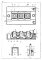
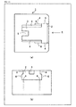
- Fig. 1 is an explanatory diagram showing the configurations of substantial parts of a semiconductor device according to Embodiment 1 of the present invention.
- Fig. 1(a) is a top view of the semiconductor device 100 according to Embodiment 1.
- Fig. 1(b) is a side view taken along the line X-X of Fig. 1(a).
- Fig. 1(c) is a front view of a main terminal 43 which is viewed in the direction of the arrow A shown in Fig. 1(a).
- Fig. 1(d) is a cross-sectional diagram showing the detail of a rectangular section B shown in Fig. 1 (b) .
- This semiconductor device 100 is, for example, an IGBT module.
- the semiconductor device 100 has a resin case 1, a heat dissipating base 41, a patterned insulating substrate 42, a nut globe 45, a main terminal 43, a control terminal 13, and a resin block 21.
- the patterned insulating substrate 42 is fixedly attached to the heat dissipating base 41.
- the resin case 1 is bonded to the rim of the heat dissipating base 41 to cover the part of the heat dissipating base 41 which is near the patterned insulating substrate 42.
- the main terminal 43 and control terminal 13, the independent terminals led (connected) to the outside, are soldered or welded onto the patterned insulating substrate 42.
- the main terminal 43 and control terminal 13 are independent terminals which are not insert-molded to the resin case 1.
- the main terminal 43 and control terminal 13 are exposed to the outside of the resin case 1 from an opening 44 and an opening 2, respectively, which are formed on an upper surface of the resin case 1.
- the main terminal 43 and control terminal 13 are fixed by the nut globe 45 and the resin block 21, respectively.
- the main terminal 43 is in the shape of a reversed "U" in which the upper part (bottom part of the "U") is exposed to the outside of the resin case 1 from the opening 44 of the upper surface of the resin case 1.
- the two leg portions 46 of the main terminal 43 (the open ends of the "U") are soldered or welded to the patterned insulating substrate 42.
- the nut globe 45 is inserted between the two leg portions 46 of the main terminal 43 so as to go under the U-shaped curve of the main terminal 43 from the opening 44 formed on a side surface of the resin case 1 in order to fixate the main terminal 43.
- the control terminal 13 is provided substantially upright on the patterned insulating substrate 42 and configured by an upright portion having its one end exposed to the outside of the resin case 1 and a coupled portion that is coupled to the other end of the upright portion to form a substantially L-shape together with the upright portion.
- One end of the coupled portion of the control terminal 13, opposite to an end of the same near the upright portion, is soldered or welded to the patterned insulating substrate 42 via a joint which is provided substantially upright on the patterned insulating substrate 42.
- a side end surface (simply referred to as "side end surface” hereinafter) 14 of the upright portion of the control terminal 13 is provided with first and second projections 16 and 17 and a concave valley 18 formed between the first projection 16 and the second projection 17.
- the resin block 21 is fitted into the valley 18 of the control terminal 13, thereby positioning and fixating the control terminal 13.
- Fig. 2 is an explanatory diagram showing the configurations of substantial parts near the control terminal of the resin case shown in Fig. 1 .
- Fig. 2(a) is a top view of the resin case 1.
- Fig. 2(b) is a front view of the resin case 1, showing Fig. 2(a) in the direction of the arrow C.
- the resin case 1 has one opening 2 that is formed so as to be connected to the upper surface and side surface of the resin case 1.
- a beam portion 3 is formed in the bottom of this opening 2.
- First hood portions (first step portions) 8 convexed to project from either sidewall 5 of the opening 2 toward the inside of the opening 2, are formed on the upper side of either sidewall 5 of the opening2.
- a second hood portion (step portion) 9, convexed to project toward the inside of the opening 2, is formed on a front sidewall of the opening 2.
- the front sidewall of the opening 2 is a sidewall positioned to face the mouth of the opening 2, which is located near the side surface of the resin case 1.
- First concave portions 6 are formed on either sidewall 5 of the opening 2 so as to extend to the outside of the opening 2.
- the first concave portions 6 are disposed away from the first hood portions 8.
- a second concave portion 7 is formed in the beam portion 3 so as to extend downward (toward the heat dissipating base 41).
- a through-hole 4 through which the control terminal 13 is passed, is formed in the beam portion 3.
- a third concave portion 10 and liquid reservoirs 11 are formed in the beam portion 3.
- An adhesive, not shown, is dropped (or applied) onto the third concave portion 10.
- the liquid reservoirs 11 prevent the adhesive from flowing toward the control terminal 13.
- Fig. 3 is an explanatory diagram showing the configuration of the control terminal shown in Fig. 1 .
- Fig. 3(a) is a side view of the control terminal 13.
- Fig. 3(b) is a top view of the control terminal 13.
- the two projections, the first and second projections 16 and 17, are formed side by side on the side end surface 14 of the control terminal 13.
- the side end surface 14 of the control terminal 13 also has the valley 18 formed between the first and second projections 16 and 17.
- a front end 27 of a convex step portion (second step portion) 26, formed on each side surface 22 of the resin block 21, is fitted into the valley 18.
- FIG. 3 represents a flat plate configuring the upright portion of the control terminal 13 (simply referred to as "flat plate” hereinafter).
- the front end 27 of the step portion 26 faces the side end surface 14 of the control terminal 13 after assembly of the semiconductor device 100.
- Reference numerals 13a to 13c represent the upright portion, coupled portion, and joint of the control terminal 13, respectively.
- Fig. 4 is an explanatory diagram showing a configuration of the resin block by which the control terminal shown in Fig. 1 is positioned and fixated.
- Fig. 4(a) is a top view of the resin block 21.
- Fig. 4(b) is a bottom view of the resin block 21.
- Fig. 4(c) is a side view of the resin block 21.
- Third projections 23 are formed on each of the side surfaces 22 of the resin block 21.
- a fourth projection 25 is formed on a bottom surface 24 of the resin block 21.
- the convex step portion 26 is formed on each side surface 22 of the resin block 21.
- the convex step portion 26 is formed on the lower side of each side surface 22 of the resin block 21, at a rear end of the resin block 21.
- the rear end of the resin block 21 is positioned at the mouth of the opening 2 on the side surface of the resin case 1 after assembly of the semiconductor device 100.
- a concave groove 29 is formed at a front end 28 of the resin block 21.
- the front end 27 of the convex step portion 26 is fitted into the valley 18 formed between the first and second projections 16 and 17 of the control terminal 13.
- the front end 28 of the resin block 21 is positioned to face the front sidewall of the opening 2 of the resin case 1 after assembly of the semiconductor device 100.
- Fig. 5 is an explanatory diagram showing the control terminal and resin block inserted and installed in the opening of the resin case shown in Fig. 2 .
- Fig. 5 (a) is a top view showing the control terminal 13 and the resin block 21 inserted and installed in the opening 2 of the resin case 1.
- Fig. 5(b) is a front view viewed in the direction of the arrow D shown in Fig. 5(a).
- Fig. 5(c) is a cross-sectional diagram showing the front end 27 of the convex step portion 26 on each side surface 22 of the resin block 21 fitted into the valley 18 formed between the first and second projections 16 and 17 of the control terminal 13.
- the flat plate 15 of the control terminal 13 is pressed by each sidewall 5 of the opening 2 of the resin case 1 and each side surface 22 of the resin block 21, thereby fixing the control terminal 13 in place in a direction perpendicular to the direction of the arrow D (a direction perpendicular to the flat plate 15 of the control terminal 13).
- the front end 27 of the convex step portion 26 on each side surface 22 of the resin block 21 is fitted into the valley 18 formed between the first and second projections 16 and 17 of the control terminal 13, thereby fixing the control terminal 13 in place in the direction of the arrow D.
- the control terminal 13 can be positioned and fixed accurately by pressing the flat plate 15 and side end surface 14 of the control terminal 13 using the sidewall 5 of the opening 2 of the resin case 1 and the resin block 21.
- a method of manufacturing the semiconductor device 100 shown in Fig. 1 is described next.
- the main terminal 43 and the control terminal 13, which are the independent terminals are soldered onto the patterned insulating substrate 42.
- the two leg portions 46 of the main terminal 43 are soldered to the patterned insulating substrate 42.
- the joint of the control terminal 13 is soldered to the patterned insulating substrate 42.
- the patterned insulating substrate 42 is then covered by the resin case 1 in such a manner that the upper surface of the main terminal 43 and the upper part of the control terminal 13 are exposed to the outside of the resin case 1, and then the lower part of the resin case 1 is bonded to the rim of the heat dissipating base 41.
- the nut globe 45 is inserted and installed so as to go under the main terminal 43 from the opening 44 provided on the side surface of the resin case 1.
- the nut globe 45 is a resin structure of a nut and a nut receiver fitted together and is in the shape of, for example, a cuboid (a rod-like cuboid). The nut is fitted into the nut receiver so as to be able to move up and down freely in the nut receiver.
- the main terminal 43 is in the shape of a reversed "U" as shown in Fig. 1(c) , and the nut globe 45 is inserted and installed so as to go under the U-shaped curve of the main terminal 43.
- the upper part of this main terminal 43 is exposed to the outside of the resin case 1.
- a mounting hole to be mounted on external wiring is formed in the upper part of the main terminal 43 which is exposed to the outside of the resin case 1.
- the control terminal 13 shown in Fig. 3 is inserted into each through-hole 4 at the bottom of the opening 2 of the resin case 1 shown in Fig. 2 , and the resin block 21 shown in Fig. 4 is inserted and installed in a lateral direction from the opening 2 on either side surface of the resin case 1, to accurately position and fix the control terminal 13.
- the lateral direction here means a direction parallel to a main surface of the patterned insulating substrate 42.
- the front end 27 of the convex step portion 26 on each side surface 22 of the resin block 21 is fitted into the valley 18 between the first and second projections 16 and 17 of the control terminal 13.
- the front end 27 of the convex step portion 26 on each side surface 22 of the resin block 21 gets caught on the second projection 17 when a compressive load is applied to the control terminal 13, and on the first projection 16 when a tensile load is applied to the same. This can prevent the control terminal 13 from sinking into the resin case 1 or being pulled out of the resin case 1.
- the control terminal 13 Because the flat plate 15 and side end surface 14 of the control terminal 13 are held between the opening 2 of the resin case 1 and the resin block 21, the control terminal 13 is positioned and fixed in the resin case 1, as accurately as the external lead terminals that are insert-molded into the resin case 1. Moreover, even when the control terminal 13 is deformed, holding the flat plate 15 and side surface 14 of the control terminal 13 between the opening 2 of the resin case 1 and the resin block 21 can correct the deformation.
- the resin block 21 When the resin block 21 is inserted into the opening 2 of the resin case 1, the third projections 23 on either side surface 22 of the resin block 21 and the fourth projection 25 on the bottom surface 24 of the resin block 21 are fitted into the first concave portions 6 of the sidewalls 5 of the opening 2 of the resin case 1 and the second concave portion 7 of the beam portion 3 at the bottom of the opening 2 of the resin case 1, respectively. As a result, the resin block 21 can accurately be positioned and fixed in the resin case 1.
- the convex step portion 26 that is formed on the lower side of each side surface 22 of the resin block 21 is fitted under the first hood portion 8 formed on the upper side of the opening 2 of the resin case 1.
- the second hood portion 9 that is formed on the front sidewall of the opening 2 of the resin case 1 is fitted into a concave groove 29 formed at the front end 28 of the resin block 21. This further fixes the resin block 21 to the resin case 1.
- the term "front” indicates the direction in which the resin block 21 is inserted from the opening 2 on each side of the resin case 1. The upper and front surfaces of the resin block 21 that are fitted into the resin case 1 are exposed from the resin case 1.
- the beam portion 3 is provided with a liquid reservoir 11, a groove for catching a liquid adhesive so that it does not flow to the control terminal 13 prior to the fixation, as shown in Fig. 2 .
- the third concave portion 10 is formed in the center of the beam portion 3 in which the liquid adhesive is disposed, and a fifth projection 30 on the bottom surface 24 of the resin block 21 is fitted into the third concave portion 10.
- control terminal 13 can accurately be positioned and fixed in the resin case 1 by inserting the front end 27 of the convex step portion 26 of the resin block 21 into the valley 18 formed between the first and second projections 16 and 17 of the control terminal 13. This can consequently prevent the control terminal 13 from sinking into the resin case 1 when a compressive load is applied to the control terminal 13.
- the control terminal 13 can also be prevented from being pulled out of the resin case 1 when a tensile load is applied to the control terminal 13.
- the side surfaces 22 and the bottom surface 24 of the resin block 21 are provided respectively with the third projections 23 and the fourth projection 25, and the sidewalls 5 and the beam portion 3 of the opening 2 of the resin case 1 are provided respectively with the first concave portions 6 and the second concave portion 7. Fitting the third projections 23 into the first concave portions 6 and the fourth projection 25 into the second concave portion 7, can prevent the resin block 21 from being removed from the resin case 1.
- the semiconductor device 100 may have the resin case 1 having as many openings 2 as the number of the control terminals 13 and as many resin blocks 21 as the number of the openings 2 of the resin case 1.
- the resin blocks 21 may be inserted into the openings 2 of the resin case 1, respectively.
- Fig. 6 is an explanatory diagram showing an example of a method of inserting the resin block of Fig. 1 into the resin case. An example in which the semiconductor device 100 has the resin case 1 with two openings 2 (openings 2a, 2b, hereinafter) and two resin blocks 21 (resin blocks 21a, 21b, hereinafter) is now described.
- the resin blocks 21a, 21b are previously connected to each other by means of a connector 31 leaving therebetween a space equal to the space between the openings 2a, 2b of the resin case 1.
- the connector 31 also referred to as "runner" is cut, for example, at the positions of the dashed lines 32 near the openings 2a, 2b of the resin case 1, thereby removing the connector 31.
- the fourth projection 25 is not necessarily formed on the bottom surface 24 of the resin block 21.
- main terminal 43 and the control terminal 13 are described as the independent terminals in Embodiment 1, the main terminal 43 is not necessarily an independent terminal.
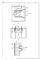
- Figs. 7 to 10 are each an explanatory diagram showing a semiconductor device of Embodiment 2 of the present invention in process of manufacture.
- the method of manufacturing a semiconductor device according to Embodiment 2 is a method of manufacturing the semiconductor device 100 of Embodiment 1 shown in Figs. 1 to 6 .
- (a) is a cross-sectional diagram showing the entire semiconductor device 100, and (b) an enlarged top view showing the area near the control terminal 13.
- a semiconductor chip not shown, the main terminal 43, and the control terminal 13 are fixated onto the patterned insulating substrate 42 by means of soldering (or sometimes welding), the patterned insulating substrate 42 being fixated onto the heat dissipating base 41.
- the resin case 1 is installed so as to cover the patterned insulating substrate 42.
- the main terminal 43 is exposed from the upper side of the opening 44 of the resin case 1, and the control terminal 13 is passed through the through-hole 4 formed in the bottom of the opening 2.
- the lower part of the resin case 1 is bonded to the rim of the heat dissipating base 41.
- the nut globe 45 is then passed under the main terminal 43 so as to be fixed to the resin case 1.
- a liquid adhesive 47a is dropped (or applied) onto the third concave portion 10 which is formed in the beam portion 3 provided in the bottom of the opening 2 of the resin case 1.
- the resin block 21 is inserted and installed in the opening 2 of the resin case 1, as shown in Fig. 9 .
- the front end 27 of the convex step portion 26 on each side surface 22 of the resin block 21 is fitted into the valley 18 formed between the first and second projections 16 and 17 (two projections) of the control terminal 13.
- the third projections 23 of the resin block 21 are fitted into the first concave portions 6 formed on the sidewalls 5 of the opening 2 of the resin case 1, and the fourth projection 25 of the resin block 21 is fitted into the second concave portion 7 formed in the beam portion 3 in the bottom of the opening 2 of the resin case 1, thereby positioning and fixing the control terminal 13 in the resin case 1.
- the liquid adhesive 47a in the third concave portion 10 is solidified, to fix the beam portion 3 at the bottom of the opening 2 of the resin case 1 to the bottom surface 24 of the resin block 21 further rigidly.
- the resin block 21 may simply be fitted into the resin case 1 without using the adhesive 47.
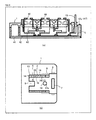
- FIG. 11 and 12 are each an explanatory diagram showing the configurations of substantial parts of a semiconductor device according to Embodiment 3 of the present invention.
- the semiconductor device according to Embodiment 3 is a modification of the semiconductor device of Embodiment 1 shown in Figs. 1 to 6 .
- Fig. 11 shows the other configurations of substantial parts near the control terminal of the resin case shown in Fig. 1 .
- Fig. 11(a) is a top view of the resin case 1.
- Fig. 11 (b) is a front view of the resin case 1, showing Fig. 11(a) in the direction of the arrow E.
- Fig. 11 and 12 are each an explanatory diagram showing the configurations of substantial parts of a semiconductor device according to Embodiment 3 of the present invention.
- the semiconductor device according to Embodiment 3 is a modification of the semiconductor device of Embodiment 1 shown in Figs. 1 to 6 .
- Fig. 11 shows the other configurations of substantial parts near the control terminal of the
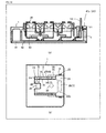
- Fig. 12 shows the other configurations of the resin block by which the control terminal shown in Fig. 1 is positioned and fixed.
- Fig. 12(a) is a top view of the resin block 21.
- Fig. 12(b) is a bottom view of the resin block 21.
- Fig. 12(c) is a side view of the resin block 21.
- the semiconductor device of Embodiment 3 shown in Figs. 11 and 12 is different from the semiconductor device of Embodiment 1 in that the resin block 21 is fitted into the openings 2 of the resin case 1 by press-fitting the resin block 21 into the openings 2 of the resin case 1 without using an adhesive.
- upper surfaces 26a of the convex step portions 26 on the side surfaces 22 of the resin block 21 are inclined downward from rear ends of the step portions 26 toward the front ends 27.
- the front ends 27 of the step portions 26 are prevented from coming into contact with the first hood portions 8 formed on the upper side of the sidewalls 5 of the opening 2 of the resin case 1, when the resin block 21 is inserted into the opening 2 of the resin case 1. Owing to such a configuration, the resin block 21 can easily be inserted into the opening 2 of the resin case 1.
- the upper surfaces 26a of the step portions 26 are inclined so that the level of the rear ends of the step portions 26 is higher than that of the front ends 27, the upper surfaces 26a of the step portions 26 can be fitted in contact with the first hood portions 8 by press-fitting the resin block 21 into the opening 2 of the resin case 1 until the resin block 21 stops. As a result, the resin block 21 is fixed in place in the insertion direction (lateral direction) thereof. Due to the downward force applied from the resin case 1 to the resin block 21, the vertical position of the resin block 21 is determined.
- the third projections 23 formed on the side surfaces 22 of the resin block 21 are fitted into the first concave portions 6 on the sidewalls 5 of the opening 2 of the resin case 1, thereby fixing the resin block 21 in place in the direction (lateral direction) perpendicular to the insertion direction. Determining the vertical and lateral position of the resin block 21 in this manner can prevent the resin block 21 from being removed from the opening 2 of the resin case 1.
- the upright portion 13a of the control terminal 13 is turned inward by the resin block 21 and consequently fixed in contact with the front sidewall of the opening 2 of the resin case 1.
- the position of the control terminal 13 can be grasped based on the front sidewall of the opening 2 of the resin case 1.
- the position of the control terminal 13 can be corrected by the resin block 21, improving the position accuracy of the control terminal 13.
- the configurations of the elements other than the upper surfaces 26a of the step portions 26 of the semiconductor device according to Embodiment 3 are the same as those of the semiconductor device shown in Figs. 1 to 6 .
- the resin block 21 can be fitted into the opening 2 of the resin case 1 without using an adhesive. This means that the third concave portion onto which an adhesive is dropped (or applied), the liquid reservoir for preventing the adhesive from flowing toward the control terminal, and the fifth projection on the bottom surface 24 of the resin block 21, are not required. Also, because the vertical movement of the resin block 21 can be inhibited by inclining the upper surfaces 26a of the step portions 26, neither the second concave portion on the lower side of the beam portion 3 of the resin block 21 nor the fourth projection on the bottom surface 24 of the resin block 21 is required.
- the fourth and fifth projections are not provided on the bottom surface 24 of the resin block 21, it is not necessary to take into consideration the heights of the fourth and fifth projections to increase the width of the opening 2 of the resin case 1 in the thickness direction. Thus, the gap between the opening 2 of the resin case 1 and the resin block 21 in the thickness direction can be reduced.
- Figs. 13 to 18 are each an explanatory diagram showing the semiconductor device of Embodiment 3 of the present invention in process of manufacture.
- the heat dissipating base 41 made of copper (Cu), becomes thermally expanded and deformed as a result of being solder-joined to the patterned insulating substrate 42. For this reason, the heat dissipating base 41 is curved to the back into a convex shape beforehand in consideration of the fact that it deforms due to thermal expansion.
- the patterned insulating substrate 42 such as a ceramic insulating substrate (DCB substrate) is joined to the front surface of the heat dissipating base 41 via a solder-joint layer, not shown, therebetween, the heat dissipating base 41 being curved to the back into a convex shape. Because the heat dissipating base 41 is deformed beforehand in consideration of the fact that it deforms due to thermal expansion as described above, solder-joining the patterned insulating substrate 42 to the heat dissipating base 41 as shown in Fig. 14 eliminates the curve of the heat dissipating base 41 and makes it flat.
- DCB substrate ceramic insulating substrate
- control terminal 13 and the main terminal 43 are soldered or welded to the circuit pattern of the patterned insulating substrate 42.
- the control terminal 13 and the main terminal 43 are normally joined at a temperature of approximately 260°C. However, since the melting point of solder is approximately 240°C, the solder joint layer joining the heat dissipating base 41 and the patterned insulating substrate 42 together might melt as a result of soldering or welding the control terminal 13 and the main terminal 43.
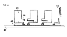
- the heat dissipating base 41 When the solder-joint layer for joining the heat dissipating base 41 and the patterned insulating substrate 42 melts, the heat dissipating base 41 returns to its initial state when it is deformed to the back into a convex shape, as shown in Fig. 15 . Therefore, the control terminal 13 and the main terminal 43 are soldered or welded to the patterned insulating substrate 42 curved to the back into a convex shape, perpendicularly to, for example, a stage on which the heat dissipating base 41 is placed, as in the case where the patterned insulating substrate 42 is flat.
- the solder-joint layer between the heat dissipating base 41 and the patterned insulating substrate 42 is cooled and solidified.
- the heat dissipating base 41 and the patterned insulating substrate 42 are consequently joined to each other again by the solder-joint layer, resulting in the elimination of the curve of the heat dissipating base 41 and making the heat dissipating base 41 and the patterned insulating substrate 42 flat.
- the control terminal 13 is joined to the patterned insulating substrate 42 when the patterned insulating substrate 42 is curved to the back into a convex shape, as described above. This means that, as shown in Fig.
- control terminal 13 is inclined to the outside after the curve of the heat dissipating base 41 and patterned insulating substrate 42 is eliminated. Consequently, the upper end of the control terminal 13 (the end that is exposed to the outside of the resin case 1) is shifted toward the outside.
- the resin case 1 is bonded to the rim of the patterned insulating substrate 42 so as to cover the patterned insulating substrate 42.
- the main terminal 43 is exposed from the upper side of the opening 44 of the resin case 1, and the control terminal 13 is passed through the through-hole 4 formed in the bottom of the opening 2.
- a simplified resin case 1 is shown in Fig. 17 (in Fig. 18 as well).
- the resin block 21 is inserted into the opening 2 of the resin case 1 so the front end 27 of the convex step portion 26 on each side surface 22 of the resin block 21 is fitted into the valley 18 formed between the first and second projections 16 and 17 of the control terminal 13.
- the resin block 21 is pressed into the opening 2 of the resin case 1 until the resin block 21 stops. Consequently, the upright portion 13a of the control terminal 13 is turned by the resin block 21 in the direction indicated by the arrow F, and the surface of the control terminal 13, opposite to the side end surface 14, comes into contact with the front sidewall of the opening 2 of the resin case 1.
- the control terminal 13 is held by the front sidewall of the opening 2 of the resin case 1 and the front ends 27 of the resin block 21.
- the flat plate 15 of the control terminal 13 is also held by the sidewalls 5 of the opening 2 of the resin case 1 and the side surfaces 22 of the resin block 21.
- the inclined upper surfaces 26a of the convex step portions 26 formed on the lower side of the side surfaces 22 of the resin block 21 are brought into contact with and fitted into the first hood portions 8 on the upper side of the opening 2 of the resin case 1, by press-fitting the resin block 21 into the opening 2 of the resin case 1.
- the third projections 23 on the side surfaces 22 of the resin block 21 are fitted into the first concave portions 6 which are formed on the sidewalls 5 of the opening 2 of the resin case 1.
- the resin block 21 is, therefore, fixed to the resin case 1 completely, and as a result the control terminal 13 is fixed in place in the lateral direction.
- the main terminal 43 is fixed by the nut globe 45 as shown in Fig. 1(b) , completing the semiconductor device according to Embodiment 3.
- the control terminal can be fixed to the resin case so as not to be shifted by external force.
- external force such as a compressive load or tensile load is applied to the control terminal, the control terminal can be prevented from sinking into the resin case or being pulled out of the resin case.
- control terminal is fixed in place in the resin case by holding the control terminal between the side surfaces of the resin block and the sidewalls of the opening of the resin case and then fitting the convex step portions of the resin block into the valley between the first and second projections of the control terminal. This can accurately determine the position of the control terminal.
- Embodiment 3 press-fitting the resin block into the opening of the resin case until the resin block stops, not only fixes the control terminal between the resin case and the resin block, but also determines the vertical and lateral position of the resin block. This can prevent the resin case from being removed from the opening of the resin case and fix the control terminal in place in the resin case.
- Embodiment 3 even when the control terminal that is bonded to the patterned insulating substrate is tilted to the outside, the control terminal can be brought into contact with the front sidewall of the opening of the resin case by turning the upright portion of the control terminal inward by means of the resin block. Therefore, even when the control terminal that is bonded to the patterned insulating substrate is tilted to the outside, the control terminal can be fixed in place in the resin case so the position of the control terminal can be grasped accurately.
- the present invention can be applied not only to each of the foregoing embodiments but also to semiconductor devices of various configurations.
- the present invention is described herein with an example in which the side end surface of the control terminal is provided with two projections and one valley therebetween, but the side end surface of the control terminal may be provided with three or more projections.
- the semiconductor device and the method of manufacturing the same according to the present invention are useful in a module semiconductor device in which an external lead terminal of a package is mounted on a patterned insulating substrate.
Landscapes
- Engineering & Computer Science (AREA)
- Microelectronics & Electronic Packaging (AREA)
- Structures Or Materials For Encapsulating Or Coating Semiconductor Devices Or Solid State Devices (AREA)
- Chemical & Material Sciences (AREA)
- Ceramic Engineering (AREA)
Abstract
Description
- The present invention relates to a semiconductor device in which a control terminal can highly accurately be fixed to a resin case, and a method of manufacturing such a semiconductor device.
- An IGBT module has conventionally been known in which a main terminal and a control terminal, which are external lead terminals, are soldered onto a conductive pattern (circuit pattern) formed on an insulating substrate (referred hereinafter as "patterned insulating substrate") (see
Patent Document 1 below, for example).Patent Document 1 uses independent terminals as the external lead terminals. The independent terminals are not fixed to a resin case, meaning they are not insert-molded into a resin case. The independent terminals are electrically connected to external wiring by nut globes which are resin structures of nuts and nut receivers fitted together. - With the recent increase in the integration density of an IGBT module, the joint between the patterned insulating substrate and the external lead terminals of the package needs to be strong and reliable in the assembly of the IGBT module. In addition, the positions to dispose the external lead terminals of the package need to be precise when mounting the external lead terminals on the patterned insulating substrate. A configuration of a conventional IGBT module is now described with reference to
Fig. 19 . -
Fig. 19 is a cross-sectional diagram showing the configurations of substantial parts of the conventional IGBT module with independent terminals. Amain terminal 53 and acontrol terminal 54, which are the independent terminals, are soldered or welded to a patternedinsulating substrate 52 which is fixedly attached onto aheat dissipating base 51. Aresin case 55 is bonded to the rim of theheat dissipating base 51. The part of theheat dissipating base 51 that is near the patternedinsulating substrate 52 is covered with theresin case 55.Openings resin case 55, so that themain terminal 53 and thecontrol terminal 54 are exposed to the outside of theresin case 55 through theopenings - Patent Document 1:
U.S. Patent Description No. 6597585 - A problem with the conventional IGBT module shown in
Fig. 19 is that thecontrol terminal 54 sinks into theresin case 55 when a compressive load is applied to thecontrol terminal 54. In a case where thecontrol terminal 54 is welded to the patternedinsulating substrate 52 or thecontrol terminal 54 is deformed very little, the patternedinsulating substrate 52 can be damaged by a compressive load applied to thecontrol terminal 54. - Another problem is that a tensile load applied to the
control terminal 54 tears the joint between thecontrol terminal 54 and the patternedinsulating substrate 52, pulling thecontrol terminal 54 out of theresin case 55. Because this conventional structure allows thecontrol terminal 54 to move easily, it is difficult to highly accurately position and fix thecontrol terminal 54 in theresin case 55. Thecontrol terminal 54 is deformed easily especially when thearm portion 58 thereof is long, making it further difficult to position thecontrol terminal 54 accurately. - In order to solve the problems of the prior art mentioned above, it is an object of the present invention to provide a semiconductor device in which a control terminal is prevented from moving up and down and can be fixed to a resin case, even when a compressive load or tensile load is applied to the control terminal, and a method of manufacturing such semiconductor device. In order to solve the problems of the prior art mentioned above, another object of the present invention is to provide a semiconductor device in which the position of the control terminal can be determined precisely, and a method of manufacturing the semiconductor device.
- The semiconductor device according to the present invention has the following characteristics for the purpose of solving the foregoing problems and achieving the objects of the present invention. A control terminal is fixedly attached to a patterned insulating substrate. A first projection is formed on the control terminal. A second projection is formed on the control terminal, away from the first projection. A concave valley is formed between the first projection and the second projection. A resin case having an opening for passing the control terminal therethrough is disposed so as to cover the patterned insulating substrate. A first concave portion is formed on a sidewall of the opening of the resin case. A beam portion is disposed at a bottom of the opening of the resin case. A second concave portion is formed in the beam portion. A resin block, which holds the control terminal together with the sidewall of the opening of the resin case to fix the control terminal to the resin case, is inserted into the opening of the resin case. A convex step portion to be fitted into the valley of the control terminal is formed in the resin block. A third projection to be fitted into the first concave portion is formed on a side surface of the resin block. A fourth projection to be fitted into the second concave portion is formed on a bottom surface of the resin block.
- According to the foregoing invention, in the semiconductor device of the present invention, the bottom surface of the resin block and the beam portion may be fixed to each other by an adhesive.
- According to the foregoing invention, in the semiconductor device of the present invention, the beam portion may be provided with a liquid reservoir which prevents the adhesive, in the form of liquid, from flowing toward the control terminal.
- The semiconductor device according to the present invention has the following characteristics for the purpose of solving the abovementioned problems and achieving the objects of the present invention. A control terminal is fixedly attached to a patterned insulating substrate. A resin case having an opening for passing the control terminal therethrough is disposed so as to cover the patterned insulating substrate. A first step portion is formed on the upper side of a sidewall of the opening of the resin case so as to project toward the inside of the opening. A resin block, which holds the control terminal together with the sidewall of the opening of the resin case to fix the control terminal to the resin case, is inserted into the opening of the resin case. A convex second step portion having an inclined upper surface fitted in contact with the first step portion is formed on a side surface of the resin block.
- The semiconductor device according to the present invention has the following characteristics for the purpose of solving the abovementioned problems and achieving the objects of the present invention. A control terminal is fixedly attached to a patterned insulating substrate. A resin case having an opening for passing the control terminal therethrough is disposed so as to cover the patterned insulating substrate. A resin block, which determines the position of the control terminal by coming into contact with a part of the control terminal and turning the part of the control terminal to a predetermined position, is inserted into the opening of the resin case.
- The method of manufacturing a semiconductor device according to the present invention is a method of manufacturing a semiconductor device which includes a control terminal that is fixedly attached to a patterned insulating substrate, and a resin case that is disposed to cover the patterned insulating substrate and has an opening for passing the control terminal therethrough, the method having the following characteristics for the purpose of solving the abovementioned problems and achieving the objects of the present invention. First of all, the control terminal is passed through the opening of the resin case in such a manner that the control terminal is partially exposed from the opening, and then the resin case is disposed so as to cover the patterned insulating substrate. Next, a resin block is inserted and installed in the opening of the resin case, and a convex step portion formed on a side surface of the resin block is fitted into a concave valley formed between two projections of the control terminal. A projection formed on the side surface of the resin block is fitted into a concave portion formed on a sidewall of the opening of the resin case. In addition, a projection formed on a bottom surface of the resin block is fitted into a concave portion which is formed in a beam portion at a bottom of the opening of the resin case. Consequently the control terminal, the resin case, and the resin block are fitted together, positioning and fixing the control terminal.
- According to the foregoing invention, the method of manufacturing a semiconductor device may further include a step of applying an adhesive to the beam portion in order to bond the resin block to the resin case.
- The method of manufacturing a semiconductor device according to the present invention is a method of manufacturing a semiconductor device which includes a control terminal that is fixedly attached to a patterned insulating substrate, and a resin case that is disposed to cover the patterned insulating substrate and has an opening for passing the control terminal therethrough, the method having the following characteristics for the purpose of solving the abovementioned problems and achieving the objects of the present invention. First of all, the method performs a step of covering the patterned insulating substrate with the resin case and passing a part of the control terminal through the opening of the resin case. Next, the method performs a step of determining the position of the control terminal by inserting a resin block into the opening of the resin case, bringing the resin block into contact with a part of the control terminal, and turning the part of the control terminal to a predetermined position.
- According to the foregoing invention, the method of manufacturing a semiconductor device according to the present invention is characterized in that the part of the control terminal is turned by the resin block until the control terminal comes into contact with the sidewall of the opening of the resin case which is at a front in a direction of insertion of the resin block.
- According to the foregoing invention, the method of manufacturing a semiconductor device according to the present invention is characterized in that an inclined upper surface of a convex step portion formed on a side surface of the resin block is fitted to a step portion which projects toward the inside of the opening of the resin case on the upper side of the sidewall of the opening, to fix the resin block to the resin case.
- According to the present invention, because the two projections provided on a side end surface of the control terminal are fitted to the convex step portion of the resin block that is inserted into the opening of the resin case, the control terminal can be fixed to the resin case so as not to be moved by external force. Hence, even when external force such as a compressive load or tensile load is applied to the control terminal, the control terminal can be prevented from sinking into the resin case or being pulled out of the resin case.
- Further, according to the present invention, as a result of holding the control terminal between the side surface of the resin block and the sidewall of the opening of the resin case and fitting the convex step portion of the resin block into the valley between the two projections of the control terminal, the control terminal can be fixed in place in the resin case. Thus, the position of the control terminal can be determined highly accurately.
- The semiconductor device and the method of manufacturing the same according to the present invention exerts the effect of fixing the control terminal to the resin case without causing vertical movement of the control terminal, even when a compressive load or tensile load is applied to the control terminal. The semiconductor device and the method of manufacturing the same according to the present invention can also exert the effect of positioning the control terminal with a high degree of accuracy.
-
-
Fig. 1 is an explanatory diagram showing the configurations of substantial parts of a semiconductor device according toEmbodiment 1 of the present invention; -
Fig. 2 is an explanatory diagram showing the configurations of substantial parts near a control terminal of a resin case shown inFig. 1 ; -
Fig. 3 is an explanatory diagram showing the configurations of the control terminal shown inFig. 1 ; -
Fig. 4 is an explanatory diagram showing the configurations of a resin block by which the control terminal shown inFig. 1 is positioned and fixed; -
Fig. 5 is an explanatory diagram showing the control terminal and resin block inserted and installed in an opening of the resin case shown inFig. 2 ; -
Fig. 6 is an explanatory diagram showing an example of a method of inserting the resin block ofFig. 1 into the resin case; -
Fig. 7 is an explanatory diagram showing a semiconductor device ofEmbodiment 2 of the present invention in process of manufacture; -
Fig. 8 is an explanatory diagram showing the semiconductor device ofEmbodiment 2 of the present invention which is in a manufacturing step following the one shown inFig. 7 ; -
Fig. 9 is an explanatory diagram showing the semiconductor device ofEmbodiment 2 of the present invention which is in a manufacturing step following the one shown inFig. 8 ; -
Fig. 10 is an explanatory diagram showing the semiconductor device ofEmbodiment 2 of the present invention which is in a manufacturing step following the one shown inFig. 9 ; -
Fig. 11 is an explanatory diagram showing the configurations of substantial parts of a semiconductor device according toEmbodiment 3 of the present invention; -
Fig. 12 is an explanatory diagram showing the configurations of substantial parts of the semiconductor device according toEmbodiment 3 of the present invention; -
Fig. 13 is an explanatory diagram showing the semiconductor device ofEmbodiment 3 of the present invention in process of manufacture; -
Fig. 14 is an explanatory diagram showing the semiconductor device ofEmbodiment 3 of the present invention in process of manufacture; -
Fig. 15 is an explanatory diagram showing the semiconductor device ofEmbodiment 3 of the present invention in process of manufacture; -
Fig. 16 is an explanatory diagram showing the semiconductor device ofEmbodiment 3 of the present invention in process of manufacture; -
Fig. 17 is an explanatory diagram showing the semiconductor device ofEmbodiment 3 of the present invention in process of manufacture; -
Fig. 18 is an explanatory diagram showing the semiconductor device ofEmbodiment 3 of the present invention in process of manufacture; and -
Fig. 19 is a cross-sectional diagram showing the configurations of substantial parts of a conventional IGBT module with independent terminals. - Preferred embodiments of a semiconductor device and a method of manufacturing the same according to the present invention are now described below in detail with reference to the accompanying drawings. In the following description of each embodiment and the accompanying drawings, like reference characters are used for indicating the same configurations, and therefore the overlapping explanations are omitted accordingly.
- The configurations of the semiconductor device according to the present invention are described with reference to
Figs. 1 to 6 .Fig. 1 is an explanatory diagram showing the configurations of substantial parts of a semiconductor device according toEmbodiment 1 of the present invention.Fig. 1(a) is a top view of thesemiconductor device 100 according toEmbodiment 1.Fig. 1(b) is a side view taken along the line X-X ofFig. 1(a). Fig. 1(c) is a front view of amain terminal 43 which is viewed in the direction of the arrow A shown inFig. 1(a). Fig. 1(d) is a cross-sectional diagram showing the detail of a rectangular section B shown inFig. 1 (b) . Thissemiconductor device 100 is, for example, an IGBT module. - As shown in
Fig. 1 , thesemiconductor device 100 has aresin case 1, aheat dissipating base 41, a patterned insulatingsubstrate 42, anut globe 45, amain terminal 43, acontrol terminal 13, and aresin block 21. The patterned insulatingsubstrate 42 is fixedly attached to theheat dissipating base 41. Theresin case 1 is bonded to the rim of theheat dissipating base 41 to cover the part of theheat dissipating base 41 which is near the patterned insulatingsubstrate 42. Themain terminal 43 andcontrol terminal 13, the independent terminals led (connected) to the outside, are soldered or welded onto the patterned insulatingsubstrate 42. Themain terminal 43 andcontrol terminal 13 are independent terminals which are not insert-molded to theresin case 1. - The
main terminal 43 andcontrol terminal 13 are exposed to the outside of theresin case 1 from anopening 44 and anopening 2, respectively, which are formed on an upper surface of theresin case 1. Themain terminal 43 andcontrol terminal 13 are fixed by thenut globe 45 and theresin block 21, respectively. In particular, themain terminal 43 is in the shape of a reversed "U" in which the upper part (bottom part of the "U") is exposed to the outside of theresin case 1 from theopening 44 of the upper surface of theresin case 1. The twoleg portions 46 of the main terminal 43 (the open ends of the "U") are soldered or welded to the patterned insulatingsubstrate 42. Thenut globe 45 is inserted between the twoleg portions 46 of themain terminal 43 so as to go under the U-shaped curve of the main terminal 43 from theopening 44 formed on a side surface of theresin case 1 in order to fixate themain terminal 43. - The
control terminal 13 is provided substantially upright on the patterned insulatingsubstrate 42 and configured by an upright portion having its one end exposed to the outside of theresin case 1 and a coupled portion that is coupled to the other end of the upright portion to form a substantially L-shape together with the upright portion. One end of the coupled portion of thecontrol terminal 13, opposite to an end of the same near the upright portion, is soldered or welded to the patterned insulatingsubstrate 42 via a joint which is provided substantially upright on the patterned insulatingsubstrate 42. A side end surface (simply referred to as "side end surface" hereinafter) 14 of the upright portion of thecontrol terminal 13 is provided with first andsecond projections concave valley 18 formed between thefirst projection 16 and thesecond projection 17. Theresin block 21 is fitted into thevalley 18 of thecontrol terminal 13, thereby positioning and fixating thecontrol terminal 13. - The configurations of the vicinity of the
control terminal 13 of theresin case 1, thecontrol terminal 13, and theresin block 21 are now described in detail.Fig. 2 is an explanatory diagram showing the configurations of substantial parts near the control terminal of the resin case shown inFig. 1 .Fig. 2(a) is a top view of theresin case 1.Fig. 2(b) is a front view of theresin case 1, showingFig. 2(a) in the direction of the arrow C. Theresin case 1 has oneopening 2 that is formed so as to be connected to the upper surface and side surface of theresin case 1. Abeam portion 3 is formed in the bottom of thisopening 2. First hood portions (first step portions) 8, convexed to project from eithersidewall 5 of theopening 2 toward the inside of theopening 2, are formed on the upper side of eithersidewall 5 of the opening2. - A second hood portion (step portion) 9, convexed to project toward the inside of the
opening 2, is formed on a front sidewall of theopening 2. The front sidewall of theopening 2 is a sidewall positioned to face the mouth of theopening 2, which is located near the side surface of theresin case 1. Firstconcave portions 6 are formed on eithersidewall 5 of theopening 2 so as to extend to the outside of theopening 2. The firstconcave portions 6 are disposed away from thefirst hood portions 8. A secondconcave portion 7 is formed in thebeam portion 3 so as to extend downward (toward the heat dissipating base 41). In addition, a through-hole 4, through which thecontrol terminal 13 is passed, is formed in thebeam portion 3. Further, a thirdconcave portion 10 andliquid reservoirs 11 are formed in thebeam portion 3. An adhesive, not shown, is dropped (or applied) onto the thirdconcave portion 10. Theliquid reservoirs 11 prevent the adhesive from flowing toward thecontrol terminal 13. -
Fig. 3 is an explanatory diagram showing the configuration of the control terminal shown inFig. 1 .Fig. 3(a) is a side view of thecontrol terminal 13.Fig. 3(b) is a top view of thecontrol terminal 13. The two projections, the first andsecond projections side end surface 14 of thecontrol terminal 13. Theside end surface 14 of thecontrol terminal 13 also has thevalley 18 formed between the first andsecond projections front end 27 of a convex step portion (second step portion) 26, formed on eachside surface 22 of theresin block 21, is fitted into thevalley 18.Reference numeral 15 shown inFig. 3 represents a flat plate configuring the upright portion of the control terminal 13 (simply referred to as "flat plate" hereinafter). Thefront end 27 of thestep portion 26 faces theside end surface 14 of thecontrol terminal 13 after assembly of thesemiconductor device 100.Reference numerals 13a to 13c represent the upright portion, coupled portion, and joint of thecontrol terminal 13, respectively. -
Fig. 4 is an explanatory diagram showing a configuration of the resin block by which the control terminal shown inFig. 1 is positioned and fixated.Fig. 4(a) is a top view of theresin block 21.Fig. 4(b) is a bottom view of theresin block 21.Fig. 4(c) is a side view of theresin block 21.Third projections 23 are formed on each of the side surfaces 22 of theresin block 21. Afourth projection 25 is formed on abottom surface 24 of theresin block 21. Theconvex step portion 26 is formed on eachside surface 22 of theresin block 21. - The
convex step portion 26 is formed on the lower side of eachside surface 22 of theresin block 21, at a rear end of theresin block 21. The rear end of theresin block 21 is positioned at the mouth of theopening 2 on the side surface of theresin case 1 after assembly of thesemiconductor device 100. Aconcave groove 29 is formed at afront end 28 of theresin block 21. Thefront end 27 of theconvex step portion 26 is fitted into thevalley 18 formed between the first andsecond projections control terminal 13. Thefront end 28 of theresin block 21 is positioned to face the front sidewall of theopening 2 of theresin case 1 after assembly of thesemiconductor device 100. -
Fig. 5 is an explanatory diagram showing the control terminal and resin block inserted and installed in the opening of the resin case shown inFig. 2 .Fig. 5 (a) is a top view showing thecontrol terminal 13 and theresin block 21 inserted and installed in theopening 2 of theresin case 1.Fig. 5(b) is a front view viewed in the direction of the arrow D shown inFig. 5(a). Fig. 5(c) is a cross-sectional diagram showing thefront end 27 of theconvex step portion 26 on eachside surface 22 of theresin block 21 fitted into thevalley 18 formed between the first andsecond projections control terminal 13. - The
flat plate 15 of thecontrol terminal 13 is pressed by eachsidewall 5 of theopening 2 of theresin case 1 and eachside surface 22 of theresin block 21, thereby fixing thecontrol terminal 13 in place in a direction perpendicular to the direction of the arrow D (a direction perpendicular to theflat plate 15 of the control terminal 13). Thefront end 27 of theconvex step portion 26 on eachside surface 22 of theresin block 21 is fitted into thevalley 18 formed between the first andsecond projections control terminal 13, thereby fixing thecontrol terminal 13 in place in the direction of the arrow D. In this manner, thecontrol terminal 13 can be positioned and fixed accurately by pressing theflat plate 15 andside end surface 14 of thecontrol terminal 13 using thesidewall 5 of theopening 2 of theresin case 1 and theresin block 21. - A method of manufacturing the
semiconductor device 100 shown inFig. 1 is described next. As shown inFig. 1 , after soldering the patterned insulatingsubstrate 42 onto theheat dissipating base 41, themain terminal 43 and thecontrol terminal 13, which are the independent terminals, are soldered onto the patterned insulatingsubstrate 42. In particular, the twoleg portions 46 of themain terminal 43 are soldered to the patterned insulatingsubstrate 42. The joint of thecontrol terminal 13 is soldered to the patterned insulatingsubstrate 42. - The patterned insulating
substrate 42 is then covered by theresin case 1 in such a manner that the upper surface of themain terminal 43 and the upper part of thecontrol terminal 13 are exposed to the outside of theresin case 1, and then the lower part of theresin case 1 is bonded to the rim of theheat dissipating base 41. Thereafter, thenut globe 45 is inserted and installed so as to go under the main terminal 43 from theopening 44 provided on the side surface of theresin case 1. Thenut globe 45 is a resin structure of a nut and a nut receiver fitted together and is in the shape of, for example, a cuboid (a rod-like cuboid). The nut is fitted into the nut receiver so as to be able to move up and down freely in the nut receiver. - The
main terminal 43 is in the shape of a reversed "U" as shown inFig. 1(c) , and thenut globe 45 is inserted and installed so as to go under the U-shaped curve of themain terminal 43. The upper part of thismain terminal 43 is exposed to the outside of theresin case 1. A mounting hole to be mounted on external wiring is formed in the upper part of themain terminal 43 which is exposed to the outside of theresin case 1. Then, thecontrol terminal 13 shown inFig. 3 is inserted into each through-hole 4 at the bottom of theopening 2 of theresin case 1 shown inFig. 2 , and theresin block 21 shown inFig. 4 is inserted and installed in a lateral direction from theopening 2 on either side surface of theresin case 1, to accurately position and fix thecontrol terminal 13. The lateral direction here means a direction parallel to a main surface of the patterned insulatingsubstrate 42. - At this moment, the
front end 27 of theconvex step portion 26 on eachside surface 22 of theresin block 21 is fitted into thevalley 18 between the first andsecond projections control terminal 13. Hence, thefront end 27 of theconvex step portion 26 on eachside surface 22 of theresin block 21 gets caught on thesecond projection 17 when a compressive load is applied to thecontrol terminal 13, and on thefirst projection 16 when a tensile load is applied to the same. This can prevent thecontrol terminal 13 from sinking into theresin case 1 or being pulled out of theresin case 1. - Because the
flat plate 15 andside end surface 14 of thecontrol terminal 13 are held between theopening 2 of theresin case 1 and theresin block 21, thecontrol terminal 13 is positioned and fixed in theresin case 1, as accurately as the external lead terminals that are insert-molded into theresin case 1. Moreover, even when thecontrol terminal 13 is deformed, holding theflat plate 15 and side surface 14 of thecontrol terminal 13 between theopening 2 of theresin case 1 and theresin block 21 can correct the deformation. - When the
resin block 21 is inserted into theopening 2 of theresin case 1, thethird projections 23 on eitherside surface 22 of theresin block 21 and thefourth projection 25 on thebottom surface 24 of theresin block 21 are fitted into the firstconcave portions 6 of thesidewalls 5 of theopening 2 of theresin case 1 and the secondconcave portion 7 of thebeam portion 3 at the bottom of theopening 2 of theresin case 1, respectively. As a result, theresin block 21 can accurately be positioned and fixed in theresin case 1. - When the
resin block 21 is inserted into theopening 2 of theresin case 1, theconvex step portion 26 that is formed on the lower side of eachside surface 22 of theresin block 21 is fitted under thefirst hood portion 8 formed on the upper side of theopening 2 of theresin case 1. In addition, thesecond hood portion 9 that is formed on the front sidewall of theopening 2 of theresin case 1 is fitted into aconcave groove 29 formed at thefront end 28 of theresin block 21. This further fixes theresin block 21 to theresin case 1. The term "front" indicates the direction in which theresin block 21 is inserted from theopening 2 on each side of theresin case 1. The upper and front surfaces of theresin block 21 that are fitted into theresin case 1 are exposed from theresin case 1. - Further, the
bottom surface 24 of theresin block 21 and thebeam portion 3 at the bottom of theopening 2 of theresin case 1 are fixed by an adhesive which is not shown. Thebeam portion 3 is provided with aliquid reservoir 11, a groove for catching a liquid adhesive so that it does not flow to thecontrol terminal 13 prior to the fixation, as shown inFig. 2 . The thirdconcave portion 10 is formed in the center of thebeam portion 3 in which the liquid adhesive is disposed, and afifth projection 30 on thebottom surface 24 of theresin block 21 is fitted into the thirdconcave portion 10. - In this manner, stronger fixation between the
resin case 1 and theresin block 21 can be realized by fitting and bonding theresin case 1 and theresin block 21 to each other by means of the adhesive. - As described above, the
control terminal 13 can accurately be positioned and fixed in theresin case 1 by inserting thefront end 27 of theconvex step portion 26 of theresin block 21 into thevalley 18 formed between the first andsecond projections control terminal 13. This can consequently prevent thecontrol terminal 13 from sinking into theresin case 1 when a compressive load is applied to thecontrol terminal 13. Thecontrol terminal 13 can also be prevented from being pulled out of theresin case 1 when a tensile load is applied to thecontrol terminal 13. - The side surfaces 22 and the
bottom surface 24 of theresin block 21 are provided respectively with thethird projections 23 and thefourth projection 25, and thesidewalls 5 and thebeam portion 3 of theopening 2 of theresin case 1 are provided respectively with the firstconcave portions 6 and the secondconcave portion 7. Fitting thethird projections 23 into the firstconcave portions 6 and thefourth projection 25 into the secondconcave portion 7, can prevent theresin block 21 from being removed from theresin case 1. - When a plurality of the
control terminals 13 are joined to the patterned insulatingsubstrate 42, thesemiconductor device 100 may have theresin case 1 having asmany openings 2 as the number of thecontrol terminals 13 and as many resin blocks 21 as the number of theopenings 2 of theresin case 1. In this case, for example, the resin blocks 21 may be inserted into theopenings 2 of theresin case 1, respectively.Fig. 6 is an explanatory diagram showing an example of a method of inserting the resin block ofFig. 1 into the resin case. An example in which thesemiconductor device 100 has theresin case 1 with two openings 2 (openings resin blocks - As shown in
Fig. 6 , upon resin-molding of theresin blocks resin blocks connector 31 leaving therebetween a space equal to the space between theopenings resin case 1. After inserting and installing theresin blocks openings resin case 1, the connector 31 (also referred to as "runner") is cut, for example, at the positions of the dashedlines 32 near theopenings resin case 1, thereby removing theconnector 31. By inserting theresin blocks openings resin case 1 in the manner described above, theresin blocks resin case 1, improving the ease of assembly of thesemiconductor device 100. - Furthermore, increasing the size of the
third projections 23 on the side surfaces 22 of theresin block 21 shown inFig. 1 , can improve the fitting between theresin block 21 and theresin case 1. Hence, theresin block 21 can accurately be fixed to theresin case 1 without using an adhesive. In so doing, thefourth projection 25 is not necessarily formed on thebottom surface 24 of theresin block 21. - Although the
main terminal 43 and thecontrol terminal 13 are described as the independent terminals inEmbodiment 1, themain terminal 43 is not necessarily an independent terminal. - The method of manufacturing a semiconductor device according to the present invention is now described in detail.
Figs. 7 to 10 are each an explanatory diagram showing a semiconductor device ofEmbodiment 2 of the present invention in process of manufacture. The method of manufacturing a semiconductor device according toEmbodiment 2 is a method of manufacturing thesemiconductor device 100 ofEmbodiment 1 shown inFigs. 1 to 6 . ThroughoutFigs. 7 to 10 ,(a) is a cross-sectional diagram showing theentire semiconductor device 100, and (b) an enlarged top view showing the area near thecontrol terminal 13. - As shown in
Fig. 7 , a semiconductor chip, not shown, themain terminal 43, and thecontrol terminal 13 are fixated onto the patterned insulatingsubstrate 42 by means of soldering (or sometimes welding), the patterned insulatingsubstrate 42 being fixated onto theheat dissipating base 41. Next, theresin case 1 is installed so as to cover the patterned insulatingsubstrate 42. Themain terminal 43 is exposed from the upper side of theopening 44 of theresin case 1, and thecontrol terminal 13 is passed through the through-hole 4 formed in the bottom of theopening 2. Subsequently, the lower part of theresin case 1 is bonded to the rim of theheat dissipating base 41. Thenut globe 45 is then passed under themain terminal 43 so as to be fixed to theresin case 1. - Next, as shown in
Fig. 8 , aliquid adhesive 47a is dropped (or applied) onto the thirdconcave portion 10 which is formed in thebeam portion 3 provided in the bottom of theopening 2 of theresin case 1. - Next, the
resin block 21 is inserted and installed in theopening 2 of theresin case 1, as shown inFig. 9 . In so doing, thefront end 27 of theconvex step portion 26 on eachside surface 22 of theresin block 21 is fitted into thevalley 18 formed between the first andsecond projections 16 and 17 (two projections) of thecontrol terminal 13. Thethird projections 23 of theresin block 21 are fitted into the firstconcave portions 6 formed on thesidewalls 5 of theopening 2 of theresin case 1, and thefourth projection 25 of theresin block 21 is fitted into the secondconcave portion 7 formed in thebeam portion 3 in the bottom of theopening 2 of theresin case 1, thereby positioning and fixing thecontrol terminal 13 in theresin case 1. - Thereafter, as shown in
Fig. 10 , theliquid adhesive 47a in the thirdconcave portion 10 is solidified, to fix thebeam portion 3 at the bottom of theopening 2 of theresin case 1 to thebottom surface 24 of theresin block 21 further rigidly. Theresin block 21 may simply be fitted into theresin case 1 without using the adhesive 47. - Another configuration of the semiconductor device of the present invention is now described as
Embodiment 3 with reference toFigs. 11 and12 .Figs. 11 and12 are each an explanatory diagram showing the configurations of substantial parts of a semiconductor device according toEmbodiment 3 of the present invention. The semiconductor device according toEmbodiment 3 is a modification of the semiconductor device ofEmbodiment 1 shown inFigs. 1 to 6 .Fig. 11 shows the other configurations of substantial parts near the control terminal of the resin case shown inFig. 1 .Fig. 11(a) is a top view of theresin case 1.Fig. 11 (b) is a front view of theresin case 1, showingFig. 11(a) in the direction of the arrow E.Fig. 12 shows the other configurations of the resin block by which the control terminal shown inFig. 1 is positioned and fixed.Fig. 12(a) is a top view of theresin block 21.Fig. 12(b) is a bottom view of theresin block 21.Fig. 12(c) is a side view of theresin block 21. - The semiconductor device of
Embodiment 3 shown inFigs. 11 and12 is different from the semiconductor device ofEmbodiment 1 in that theresin block 21 is fitted into theopenings 2 of theresin case 1 by press-fitting theresin block 21 into theopenings 2 of theresin case 1 without using an adhesive. In particular,upper surfaces 26a of theconvex step portions 26 on the side surfaces 22 of theresin block 21 are inclined downward from rear ends of thestep portions 26 toward the front ends 27. - By taking advantage of the inclined
upper surfaces 26a of thestep portions 26, the front ends 27 of thestep portions 26 are prevented from coming into contact with thefirst hood portions 8 formed on the upper side of thesidewalls 5 of theopening 2 of theresin case 1, when theresin block 21 is inserted into theopening 2 of theresin case 1. Owing to such a configuration, theresin block 21 can easily be inserted into theopening 2 of theresin case 1. - Because the
upper surfaces 26a of thestep portions 26 are inclined so that the level of the rear ends of thestep portions 26 is higher than that of the front ends 27, theupper surfaces 26a of thestep portions 26 can be fitted in contact with thefirst hood portions 8 by press-fitting theresin block 21 into theopening 2 of theresin case 1 until theresin block 21 stops. As a result, theresin block 21 is fixed in place in the insertion direction (lateral direction) thereof. Due to the downward force applied from theresin case 1 to theresin block 21, the vertical position of theresin block 21 is determined. As withEmbodiment 1, thethird projections 23 formed on the side surfaces 22 of theresin block 21 are fitted into the firstconcave portions 6 on thesidewalls 5 of theopening 2 of theresin case 1, thereby fixing theresin block 21 in place in the direction (lateral direction) perpendicular to the insertion direction. Determining the vertical and lateral position of theresin block 21 in this manner can prevent theresin block 21 from being removed from theopening 2 of theresin case 1. - Further, as a result of press-fitting the
resin block 21 into theopening 2 of theresin case 1 until theresin block 21 stops, theupright portion 13a of thecontrol terminal 13 is turned inward by theresin block 21 and consequently fixed in contact with the front sidewall of theopening 2 of theresin case 1. Thus, the position of thecontrol terminal 13 can be grasped based on the front sidewall of theopening 2 of theresin case 1. Even when thecontrol terminal 13 joined to the patterned insulatingsubstrate 42 is inclined toward the outside, the position of thecontrol terminal 13 can be corrected by theresin block 21, improving the position accuracy of thecontrol terminal 13. The configurations of the elements other than theupper surfaces 26a of thestep portions 26 of the semiconductor device according toEmbodiment 3 are the same as those of the semiconductor device shown inFigs. 1 to 6 . - In
Embodiment 3 theresin block 21 can be fitted into theopening 2 of theresin case 1 without using an adhesive. This means that the third concave portion onto which an adhesive is dropped (or applied), the liquid reservoir for preventing the adhesive from flowing toward the control terminal, and the fifth projection on thebottom surface 24 of theresin block 21, are not required. Also, because the vertical movement of theresin block 21 can be inhibited by inclining theupper surfaces 26a of thestep portions 26, neither the second concave portion on the lower side of thebeam portion 3 of theresin block 21 nor the fourth projection on thebottom surface 24 of theresin block 21 is required. When the fourth and fifth projections are not provided on thebottom surface 24 of theresin block 21, it is not necessary to take into consideration the heights of the fourth and fifth projections to increase the width of theopening 2 of theresin case 1 in the thickness direction. Thus, the gap between theopening 2 of theresin case 1 and theresin block 21 in the thickness direction can be reduced. - A method of manufacturing the semiconductor device shown in
Figs. 11 and12 is described next.Figs. 13 to 18 are each an explanatory diagram showing the semiconductor device ofEmbodiment 3 of the present invention in process of manufacture. Theheat dissipating base 41, made of copper (Cu), becomes thermally expanded and deformed as a result of being solder-joined to the patterned insulatingsubstrate 42. For this reason, theheat dissipating base 41 is curved to the back into a convex shape beforehand in consideration of the fact that it deforms due to thermal expansion. - Next, the patterned insulating
substrate 42 such as a ceramic insulating substrate (DCB substrate) is joined to the front surface of theheat dissipating base 41 via a solder-joint layer, not shown, therebetween, theheat dissipating base 41 being curved to the back into a convex shape. Because theheat dissipating base 41 is deformed beforehand in consideration of the fact that it deforms due to thermal expansion as described above, solder-joining the patterned insulatingsubstrate 42 to theheat dissipating base 41 as shown inFig. 14 eliminates the curve of theheat dissipating base 41 and makes it flat. - Next, the
control terminal 13 and themain terminal 43 are soldered or welded to the circuit pattern of the patterned insulatingsubstrate 42. Thecontrol terminal 13 and themain terminal 43 are normally joined at a temperature of approximately 260°C. However, since the melting point of solder is approximately 240°C, the solder joint layer joining theheat dissipating base 41 and the patterned insulatingsubstrate 42 together might melt as a result of soldering or welding thecontrol terminal 13 and themain terminal 43. - When the solder-joint layer for joining the
heat dissipating base 41 and the patterned insulatingsubstrate 42 melts, theheat dissipating base 41 returns to its initial state when it is deformed to the back into a convex shape, as shown inFig. 15 . Therefore, thecontrol terminal 13 and themain terminal 43 are soldered or welded to the patterned insulatingsubstrate 42 curved to the back into a convex shape, perpendicularly to, for example, a stage on which theheat dissipating base 41 is placed, as in the case where the patterned insulatingsubstrate 42 is flat. - Thereafter, the solder-joint layer between the
heat dissipating base 41 and the patterned insulatingsubstrate 42 is cooled and solidified. Theheat dissipating base 41 and the patterned insulatingsubstrate 42 are consequently joined to each other again by the solder-joint layer, resulting in the elimination of the curve of theheat dissipating base 41 and making theheat dissipating base 41 and the patterned insulatingsubstrate 42 flat. However, thecontrol terminal 13 is joined to the patterned insulatingsubstrate 42 when the patterned insulatingsubstrate 42 is curved to the back into a convex shape, as described above. This means that, as shown inFig. 16 , thecontrol terminal 13 is inclined to the outside after the curve of theheat dissipating base 41 and patterned insulatingsubstrate 42 is eliminated. Consequently, the upper end of the control terminal 13 (the end that is exposed to the outside of the resin case 1) is shifted toward the outside. - Next, as shown in
Fig. 17 , theresin case 1 is bonded to the rim of the patterned insulatingsubstrate 42 so as to cover the patterned insulatingsubstrate 42. In this case, themain terminal 43 is exposed from the upper side of theopening 44 of theresin case 1, and thecontrol terminal 13 is passed through the through-hole 4 formed in the bottom of theopening 2. For the purpose of clearly illustrating thecontrol terminal 13, asimplified resin case 1 is shown inFig. 17 (inFig. 18 as well). - As shown in
Fig. 18 , theresin block 21 is inserted into theopening 2 of theresin case 1 so thefront end 27 of theconvex step portion 26 on eachside surface 22 of theresin block 21 is fitted into thevalley 18 formed between the first andsecond projections control terminal 13. Theresin block 21 is pressed into theopening 2 of theresin case 1 until theresin block 21 stops. Consequently, theupright portion 13a of thecontrol terminal 13 is turned by theresin block 21 in the direction indicated by the arrow F, and the surface of thecontrol terminal 13, opposite to theside end surface 14, comes into contact with the front sidewall of theopening 2 of theresin case 1. As a result, thecontrol terminal 13 is held by the front sidewall of theopening 2 of theresin case 1 and the front ends 27 of theresin block 21. Theflat plate 15 of thecontrol terminal 13 is also held by thesidewalls 5 of theopening 2 of theresin case 1 and the side surfaces 22 of theresin block 21. - The inclined
upper surfaces 26a of theconvex step portions 26 formed on the lower side of the side surfaces 22 of theresin block 21 are brought into contact with and fitted into thefirst hood portions 8 on the upper side of theopening 2 of theresin case 1, by press-fitting theresin block 21 into theopening 2 of theresin case 1. Within theopening 2 of theresin case 1, thethird projections 23 on the side surfaces 22 of theresin block 21 are fitted into the firstconcave portions 6 which are formed on thesidewalls 5 of theopening 2 of theresin case 1. Theresin block 21 is, therefore, fixed to theresin case 1 completely, and as a result thecontrol terminal 13 is fixed in place in the lateral direction. Subsequently, themain terminal 43 is fixed by thenut globe 45 as shown inFig. 1(b) , completing the semiconductor device according toEmbodiment 3. - According to each of the embodiments described above, by fitting the first and second projections of the side end surfaces of the control terminal to the convex step portions of the resin block inserted into the opening of the resin case, the control terminal can be fixed to the resin case so as not to be shifted by external force. Thus, even when external force such as a compressive load or tensile load is applied to the control terminal, the control terminal can be prevented from sinking into the resin case or being pulled out of the resin case.
- In addition, according to the foregoing embodiments, the control terminal is fixed in place in the resin case by holding the control terminal between the side surfaces of the resin block and the sidewalls of the opening of the resin case and then fitting the convex step portions of the resin block into the valley between the first and second projections of the control terminal. This can accurately determine the position of the control terminal.
- According to
Embodiment 3, press-fitting the resin block into the opening of the resin case until the resin block stops, not only fixes the control terminal between the resin case and the resin block, but also determines the vertical and lateral position of the resin block. This can prevent the resin case from being removed from the opening of the resin case and fix the control terminal in place in the resin case. According toEmbodiment 3, even when the control terminal that is bonded to the patterned insulating substrate is tilted to the outside, the control terminal can be brought into contact with the front sidewall of the opening of the resin case by turning the upright portion of the control terminal inward by means of the resin block. Therefore, even when the control terminal that is bonded to the patterned insulating substrate is tilted to the outside, the control terminal can be fixed in place in the resin case so the position of the control terminal can be grasped accurately. - The present invention can be applied not only to each of the foregoing embodiments but also to semiconductor devices of various configurations. The present invention is described herein with an example in which the side end surface of the control terminal is provided with two projections and one valley therebetween, but the side end surface of the control terminal may be provided with three or more projections.
- As described above, the semiconductor device and the method of manufacturing the same according to the present invention are useful in a module semiconductor device in which an external lead terminal of a package is mounted on a patterned insulating substrate.
-
- 1
- Resin case
- 2, 2a, 2b
- Opening for inserting control terminal
- 3
- Beam portion
- 4
- Through-hole
- 5
- Sidewall of opening
- 6
- First concave portion
- 7
- Second concave portion
- 8
- First hood portion
- 9
- Second hood portion
- 10
- Third concave portion
- 11
- Liquid reservoir
- 13
- Control terminal
- 13a
- Upright portion of control terminal
- 13b
- Coupled portion of control terminal
- 13c
- Joint of control terminal
- 14
- Side end surface
- 15
- Flat plate
- 16
- First projection
- 17
- Second projection
- 18
- Valley
- 21,
- 21a, 21b Resin block
- 22
- Side surface of resin block
- 23
- Third projection
- 24
- Bottom surface of resin block
- 25
- Fourth projection
- 26
- Convex step portion on side surface of resin block
- 26a
- Inclined upper surface of convex step portion on side surface of resin block
- 27
- Front end of convex step portion
- 28
- Front end of resin block
- 29
- Concave groove of resin block
- 30
- Fifth projection (fitted into concave portion 10)
- 31
- Connector
- 32
- Dotted line near opening of resin case
- 41
- Heat dissipating base
- 42
- Patterned insulating substrate
- 43
- Main terminal
- 44
- Opening for inserting main terminal
- 45
- Nut globe
- 46
- Legs of main terminal
- 47
- Adhesive
- 47a
- Liquid adhesive
- 47b
- Solidified adhesive
Claims (10)
- A semiconductor device, comprising:a control terminal that is fixedly attached to a patterned insulating substrate;a first projection that is formed on the control terminal;a second projection that is formed on the control terminal, away from the first projection;a concave valley that is formed between the first projection and the second projection;a resin case that is disposed so as to cover the patterned insulating substrate and has an opening for passing the control terminal therethrough;a first concave portion that is formed on a sidewall of the opening of the resin case;a beam portion that is disposed at a bottom of the opening of the resin case;a second concave portion that is formed in the beam portion;a resin block that is inserted into the opening of the resin case and holds the control terminal together with the sidewall of the opening of the resin case to fix the control terminal to the resin case;a convex step portion that is formed in the resin block and fitted into the valley of the control terminal;a third projection that is formed on a side surface of the resin block and fitted into the first concave portion; anda fourth projection that is formed on a bottom surface of the resin block and fitted into the second concave portion.
- The semiconductor device according to claim 1, wherein the bottom surface of the resin block and the beam portion is fixed to each other by an adhesive.
- The semiconductor device according to claim 2, wherein the beam portion is provided with a liquid reservoir which prevents the adhesive, in the form of liquid, from flowing toward the control terminal.
- A semiconductor device, comprising:a control terminal that is fixedly attached to a patterned insulating substrate;a resin case that is disposed so as to cover the patterned insulating substrate and has an opening for passing the control terminal therethrough;a first step portion that is formed on the upper side of a sidewall of the opening of the resin case so as to project toward the inside of the opening;a resin block that is inserted into the opening of the resin case and holds the control terminal together with the sidewall of the opening of the resin case to fix the control terminal to the resin case; anda convex second step portion that is formed on a side surface of the resin block and has an inclined upper surface fitted in contact with the first step portion.
- A semiconductor device, comprising:a control terminal that is fixedly attached to a patterned insulating substrate;a resin case that is disposed so as to cover the patterned insulating substrate and has an opening for passing the control terminal therethrough; anda resin block that is inserted into the opening of the resin case and determines a position of the control terminal by coming into contact with a part of the control terminal and turning the part of the control terminal to a predetermined position.
- A method of manufacturing a semiconductor device which includes a control terminal that is fixedly attached to a patterned insulating substrate, and a resin case that is disposed so as to cover the patterned insulating substrate and has an opening for passing the control terminal therethrough, the method comprising the steps of:passing the control terminal through the opening of the resin case in such a manner that the control terminal is partially exposed from the opening and then covering the patterned insulating substrate with the resin case; andinserting and installing a resin block in the opening of the resin case, fitting a convex step portion formed on a side surface of the resin block into a concave valley formed between two projections of the control terminal, fitting a projection formed on the side surface of the resin block into a concave portion formed on a sidewall of the opening of the resin case, and fitting a projection formed on a bottom surface of the resin block into a concave portion which is formed in a beam portion at a bottom of the opening of the resin case, thereby positioning and fixing the control terminal.
- The method according to claim 6, further comprising a step of applying an adhesive to the beam portion in order to bond the resin block to the resin case.
- A method of manufacturing a semiconductor device which includes a control terminal that is fixedly attached to a patterned insulating substrate, and a resin case that is disposed so as to cover the patterned insulating substrate and has an opening for passing the control terminal therethrough, the method comprising the steps of:covering the patterned insulating substrate with the resin case and passing a part of the control terminal through the opening of the resin case; anddetermining a position of the control terminal by inserting a resin block into the opening of the resin case, bringing the resin block into contact with a part of the control terminal, and turning the part of the control terminal to a predetermined position.
- The method according to claim 8, wherein the part of the control terminal is turned by the resin block until the control terminal comes into contact with a sidewall of the opening of the resin case which is at a front in a direction of insertion of the resin block.
- The method according to claim 8 or 9, wherein an inclined upper surface of a convex step portion formed on a side surface of the resin block is fitted to a step portion which projects toward the inside of the opening of the resin case on the upper side of the sidewall of the opening, to fix the resin block to the resin case.
Applications Claiming Priority (2)
| Application Number | Priority Date | Filing Date | Title |
|---|---|---|---|
| JP2011183836 | 2011-08-25 | ||
| PCT/JP2012/071440 WO2013027826A1 (en) | 2011-08-25 | 2012-08-24 | Semiconductor device and semiconductor device manufacturing method |
Publications (3)
| Publication Number | Publication Date |
|---|---|
| EP2750187A1 true EP2750187A1 (en) | 2014-07-02 |
| EP2750187A4 EP2750187A4 (en) | 2015-08-05 |
| EP2750187B1 EP2750187B1 (en) | 2020-01-01 |
Family
ID=47746561
Family Applications (1)
| Application Number | Title | Priority Date | Filing Date |
|---|---|---|---|
| EP12825504.9A Active EP2750187B1 (en) | 2011-08-25 | 2012-08-24 | Semiconductor device and semiconductor device manufacturing method |
Country Status (5)
| Country | Link |
|---|---|
| US (2) | US9078355B2 (en) |
| EP (1) | EP2750187B1 (en) |
| JP (1) | JP5861711B2 (en) |
| CN (1) | CN103650138B (en) |
| WO (1) | WO2013027826A1 (en) |
Families Citing this family (8)
| Publication number | Priority date | Publication date | Assignee | Title |
|---|---|---|---|---|
| JP5954491B2 (en) * | 2013-03-21 | 2016-07-20 | 三菱電機株式会社 | Semiconductor device |
| WO2015141325A1 (en) * | 2014-03-19 | 2015-09-24 | 富士電機株式会社 | Semiconductor device and method for manufacturing same |
| WO2016059916A1 (en) * | 2014-10-14 | 2016-04-21 | 富士電機株式会社 | Semiconductor device |
| CN106796934B (en) * | 2015-04-10 | 2019-12-10 | 富士电机株式会社 | Semiconductor device with a plurality of semiconductor chips |
| JP6578795B2 (en) * | 2015-08-04 | 2019-09-25 | 富士電機株式会社 | Semiconductor device and manufacturing method of semiconductor device |
| CN106684043B (en) * | 2016-12-13 | 2019-05-03 | 华润微电子(重庆)有限公司 | An anti-static IGBT module |
| USD949808S1 (en) * | 2020-11-27 | 2022-04-26 | Sansha Electric Manufacturing Co., Ltd. | Semiconductor device |
| JP2023085776A (en) | 2021-12-09 | 2023-06-21 | 富士電機株式会社 | semiconductor module |
Family Cites Families (14)
| Publication number | Priority date | Publication date | Assignee | Title |
|---|---|---|---|---|
| JP2867753B2 (en) * | 1991-02-25 | 1999-03-10 | 富士電機株式会社 | Semiconductor device |
| JP3120575B2 (en) * | 1992-06-29 | 2000-12-25 | 富士電機株式会社 | Semiconductor device |
| JPH06268102A (en) * | 1993-01-13 | 1994-09-22 | Fuji Electric Co Ltd | Resin-sealed semiconductor device |
| JP2973799B2 (en) * | 1993-04-23 | 1999-11-08 | 富士電機株式会社 | Power transistor module |
| JPH087956A (en) * | 1994-06-23 | 1996-01-12 | Fuji Electric Co Ltd | Semiconductor device terminal assembly structure |
| JP3025083U (en) | 1995-11-22 | 1996-06-07 | 富士電機株式会社 | Terminal structure of semiconductor device |
| JP3610749B2 (en) | 1997-12-04 | 2005-01-19 | 富士電機デバイステクノロジー株式会社 | Semiconductor device package, manufacturing method thereof, and semiconductor device using the same |
| JP2000183276A (en) * | 1998-12-15 | 2000-06-30 | Mitsubishi Electric Corp | Semiconductor power module |
| JP3519300B2 (en) * | 1999-01-11 | 2004-04-12 | 富士電機デバイステクノロジー株式会社 | Power module package structure |
| WO2000055917A1 (en) * | 1999-03-17 | 2000-09-21 | eupec Europäische Gesellschaft für Leistungshalbleiter mbH & Co. KG | Power semiconductor module |
| JP4349437B2 (en) * | 2007-06-04 | 2009-10-21 | 株式会社デンソー | Manufacturing method of electronic device |
| US7768109B2 (en) * | 2007-08-24 | 2010-08-03 | Kabushiki Kaisha Toshiba | Semiconductor device and method of manufacturing the same |
| US7816781B2 (en) * | 2007-10-02 | 2010-10-19 | Infineon Technologies Ag | Power semiconductor module |
| JP5113815B2 (en) * | 2009-09-18 | 2013-01-09 | 株式会社東芝 | Power module |
-
2012
- 2012-08-24 EP EP12825504.9A patent/EP2750187B1/en active Active
- 2012-08-24 WO PCT/JP2012/071440 patent/WO2013027826A1/en not_active Ceased
- 2012-08-24 US US14/232,780 patent/US9078355B2/en active Active
- 2012-08-24 JP JP2013530071A patent/JP5861711B2/en active Active
- 2012-08-24 CN CN201280034713.9A patent/CN103650138B/en active Active
-
2015
- 2015-05-04 US US14/703,313 patent/US9136225B2/en active Active
Also Published As
| Publication number | Publication date |
|---|---|
| CN103650138B (en) | 2016-06-22 |
| US9136225B2 (en) | 2015-09-15 |
| US9078355B2 (en) | 2015-07-07 |
| JP5861711B2 (en) | 2016-02-16 |
| WO2013027826A1 (en) | 2013-02-28 |
| US20150235965A1 (en) | 2015-08-20 |
| EP2750187B1 (en) | 2020-01-01 |
| US20140168922A1 (en) | 2014-06-19 |
| CN103650138A (en) | 2014-03-19 |
| EP2750187A4 (en) | 2015-08-05 |
| JPWO2013027826A1 (en) | 2015-03-19 |
Similar Documents
| Publication | Publication Date | Title |
|---|---|---|
| US9136225B2 (en) | Semiconductor device manufacturing method | |
| US8933554B2 (en) | Semiconductor device and method for manufacturing semiconductor device | |
| JP6057016B2 (en) | Semiconductor device and manufacturing method thereof | |
| JP5538019B2 (en) | Connector unit and electronic circuit device | |
| CN104064493A (en) | Manufacturing method of semiconductor device and mounting jig | |
| US20130221504A1 (en) | Semiconductor module and method of manufacturing a semiconductor module | |
| CN101877339A (en) | Lead frame | |
| US8242587B2 (en) | Electronic device and pressure sensor | |
| JP2002026195A (en) | Resin-sealed semiconductor device and manufacturing method thereof | |
| US20120074556A1 (en) | Semiconductor power module and method of manufacturing the same | |
| EP0810660A1 (en) | Surface mount semiconductor diode device | |
| JPH0812895B2 (en) | Semiconductor device mounted pin grid array package substrate | |
| JP5217013B2 (en) | Power conversion device and manufacturing method thereof | |
| JP2005353854A (en) | Wiring substrate and semiconductor device using the same | |
| JP4750376B2 (en) | Lead wire joining method | |
| JPH06252326A (en) | Multi-terminal component, wiring substrate and packaging structure of multi-terminal component | |
| JPH10242328A (en) | Circuit board, circuit module having this circuit board, and electronic device having this circuit module | |
| US20260123550A1 (en) | Substrate bonding systems and related methods | |
| CN101642004A (en) | Method for assembling an electrical component to a contact element and contact element having an electrical component | |
| JPH1140605A (en) | Tape carrier package | |
| US20070085192A1 (en) | Method for producing micromechanical components in integrated circuits and arrangement of a semiconductor on a substrate | |
| KR20190032013A (en) | Mounting method of semiconductor chip using press-fit and semiconductor chip package | |
| JPH07249653A (en) | Semiconductor device, manufacturing method thereof, and mounting method thereof | |
| JP2010003745A (en) | Soldering method and soldering structure | |
| JPH0997859A (en) | Lead frame, manufacturing method thereof, and manufacturing method of electronic component mounting substrate |
Legal Events
| Date | Code | Title | Description |
|---|---|---|---|
| PUAI | Public reference made under article 153(3) epc to a published international application that has entered the european phase |
Free format text: ORIGINAL CODE: 0009012 |
|
| 17P | Request for examination filed |
Effective date: 20140325 |
|
| AK | Designated contracting states |
Kind code of ref document: A1 Designated state(s): AL AT BE BG CH CY CZ DE DK EE ES FI FR GB GR HR HU IE IS IT LI LT LU LV MC MK MT NL NO PL PT RO RS SE SI SK SM TR |
|
| DAX | Request for extension of the european patent (deleted) | ||
| RA4 | Supplementary search report drawn up and despatched (corrected) |
Effective date: 20150707 |
|
| RIC1 | Information provided on ipc code assigned before grant |
Ipc: H01L 23/373 20060101ALI20150701BHEP Ipc: H01L 23/04 20060101ALI20150701BHEP Ipc: H01L 25/07 20060101AFI20150701BHEP Ipc: H01L 23/498 20060101ALI20150701BHEP Ipc: H05K 5/02 20060101ALI20150701BHEP Ipc: H01L 23/049 20060101ALI20150701BHEP Ipc: H01L 23/48 20060101ALI20150701BHEP |
|
| GRAP | Despatch of communication of intention to grant a patent |
Free format text: ORIGINAL CODE: EPIDOSNIGR1 |
|
| STAA | Information on the status of an ep patent application or granted ep patent |
Free format text: STATUS: GRANT OF PATENT IS INTENDED |
|
| RIC1 | Information provided on ipc code assigned before grant |
Ipc: H05K 5/02 20060101ALI20190619BHEP Ipc: H01L 29/66 20060101ALI20190619BHEP Ipc: H01L 25/07 20060101AFI20190619BHEP Ipc: H01L 23/049 20060101ALI20190619BHEP Ipc: H01L 23/373 20060101ALI20190619BHEP Ipc: H01L 23/29 20060101ALI20190619BHEP Ipc: H01L 23/36 20060101ALI20190619BHEP Ipc: H01L 23/48 20060101ALI20190619BHEP Ipc: H01L 23/14 20060101ALI20190619BHEP Ipc: H01L 23/544 20060101ALI20190619BHEP Ipc: H01L 23/31 20060101ALI20190619BHEP Ipc: H01L 23/10 20060101ALI20190619BHEP Ipc: H01L 23/053 20060101ALI20190619BHEP Ipc: H01L 23/498 20060101ALI20190619BHEP Ipc: H01L 21/56 20060101ALI20190619BHEP Ipc: H01L 23/04 20060101ALI20190619BHEP Ipc: H01L 23/34 20060101ALI20190619BHEP |
|
| INTG | Intention to grant announced |
Effective date: 20190718 |
|
| GRAS | Grant fee paid |
Free format text: ORIGINAL CODE: EPIDOSNIGR3 |
|
| GRAA | (expected) grant |
Free format text: ORIGINAL CODE: 0009210 |
|
| STAA | Information on the status of an ep patent application or granted ep patent |
Free format text: STATUS: THE PATENT HAS BEEN GRANTED |
|
| AK | Designated contracting states |
Kind code of ref document: B1 Designated state(s): AL AT BE BG CH CY CZ DE DK EE ES FI FR GB GR HR HU IE IS IT LI LT LU LV MC MK MT NL NO PL PT RO RS SE SI SK SM TR |
|
| REG | Reference to a national code |
Ref country code: GB Ref legal event code: FG4D |
|
| REG | Reference to a national code |
Ref country code: CH Ref legal event code: EP Ref country code: AT Ref legal event code: REF Ref document number: 1220870 Country of ref document: AT Kind code of ref document: T Effective date: 20200115 |
|
| REG | Reference to a national code |
Ref country code: IE Ref legal event code: FG4D |
|
| REG | Reference to a national code |
Ref country code: DE Ref legal event code: R096 Ref document number: 602012066966 Country of ref document: DE |
|
| REG | Reference to a national code |
Ref country code: NL Ref legal event code: MP Effective date: 20200101 |
|
| REG | Reference to a national code |
Ref country code: LT Ref legal event code: MG4D |
|
| PG25 | Lapsed in a contracting state [announced via postgrant information from national office to epo] |
Ref country code: LT Free format text: LAPSE BECAUSE OF FAILURE TO SUBMIT A TRANSLATION OF THE DESCRIPTION OR TO PAY THE FEE WITHIN THE PRESCRIBED TIME-LIMIT Effective date: 20200101 Ref country code: RS Free format text: LAPSE BECAUSE OF FAILURE TO SUBMIT A TRANSLATION OF THE DESCRIPTION OR TO PAY THE FEE WITHIN THE PRESCRIBED TIME-LIMIT Effective date: 20200101 Ref country code: NL Free format text: LAPSE BECAUSE OF FAILURE TO SUBMIT A TRANSLATION OF THE DESCRIPTION OR TO PAY THE FEE WITHIN THE PRESCRIBED TIME-LIMIT Effective date: 20200101 Ref country code: FI Free format text: LAPSE BECAUSE OF FAILURE TO SUBMIT A TRANSLATION OF THE DESCRIPTION OR TO PAY THE FEE WITHIN THE PRESCRIBED TIME-LIMIT Effective date: 20200101 Ref country code: NO Free format text: LAPSE BECAUSE OF FAILURE TO SUBMIT A TRANSLATION OF THE DESCRIPTION OR TO PAY THE FEE WITHIN THE PRESCRIBED TIME-LIMIT Effective date: 20200401 Ref country code: PT Free format text: LAPSE BECAUSE OF FAILURE TO SUBMIT A TRANSLATION OF THE DESCRIPTION OR TO PAY THE FEE WITHIN THE PRESCRIBED TIME-LIMIT Effective date: 20200527 Ref country code: CZ Free format text: LAPSE BECAUSE OF FAILURE TO SUBMIT A TRANSLATION OF THE DESCRIPTION OR TO PAY THE FEE WITHIN THE PRESCRIBED TIME-LIMIT Effective date: 20200101 |
|
| PG25 | Lapsed in a contracting state [announced via postgrant information from national office to epo] |
Ref country code: SE Free format text: LAPSE BECAUSE OF FAILURE TO SUBMIT A TRANSLATION OF THE DESCRIPTION OR TO PAY THE FEE WITHIN THE PRESCRIBED TIME-LIMIT Effective date: 20200101 Ref country code: LV Free format text: LAPSE BECAUSE OF FAILURE TO SUBMIT A TRANSLATION OF THE DESCRIPTION OR TO PAY THE FEE WITHIN THE PRESCRIBED TIME-LIMIT Effective date: 20200101 Ref country code: GR Free format text: LAPSE BECAUSE OF FAILURE TO SUBMIT A TRANSLATION OF THE DESCRIPTION OR TO PAY THE FEE WITHIN THE PRESCRIBED TIME-LIMIT Effective date: 20200402 Ref country code: HR Free format text: LAPSE BECAUSE OF FAILURE TO SUBMIT A TRANSLATION OF THE DESCRIPTION OR TO PAY THE FEE WITHIN THE PRESCRIBED TIME-LIMIT Effective date: 20200101 Ref country code: IS Free format text: LAPSE BECAUSE OF FAILURE TO SUBMIT A TRANSLATION OF THE DESCRIPTION OR TO PAY THE FEE WITHIN THE PRESCRIBED TIME-LIMIT Effective date: 20200501 Ref country code: BG Free format text: LAPSE BECAUSE OF FAILURE TO SUBMIT A TRANSLATION OF THE DESCRIPTION OR TO PAY THE FEE WITHIN THE PRESCRIBED TIME-LIMIT Effective date: 20200401 |
|
| REG | Reference to a national code |
Ref country code: DE Ref legal event code: R097 Ref document number: 602012066966 Country of ref document: DE |
|
| PG25 | Lapsed in a contracting state [announced via postgrant information from national office to epo] |
Ref country code: RO Free format text: LAPSE BECAUSE OF FAILURE TO SUBMIT A TRANSLATION OF THE DESCRIPTION OR TO PAY THE FEE WITHIN THE PRESCRIBED TIME-LIMIT Effective date: 20200101 Ref country code: SK Free format text: LAPSE BECAUSE OF FAILURE TO SUBMIT A TRANSLATION OF THE DESCRIPTION OR TO PAY THE FEE WITHIN THE PRESCRIBED TIME-LIMIT Effective date: 20200101 Ref country code: ES Free format text: LAPSE BECAUSE OF FAILURE TO SUBMIT A TRANSLATION OF THE DESCRIPTION OR TO PAY THE FEE WITHIN THE PRESCRIBED TIME-LIMIT Effective date: 20200101 Ref country code: DK Free format text: LAPSE BECAUSE OF FAILURE TO SUBMIT A TRANSLATION OF THE DESCRIPTION OR TO PAY THE FEE WITHIN THE PRESCRIBED TIME-LIMIT Effective date: 20200101 Ref country code: EE Free format text: LAPSE BECAUSE OF FAILURE TO SUBMIT A TRANSLATION OF THE DESCRIPTION OR TO PAY THE FEE WITHIN THE PRESCRIBED TIME-LIMIT Effective date: 20200101 Ref country code: SM Free format text: LAPSE BECAUSE OF FAILURE TO SUBMIT A TRANSLATION OF THE DESCRIPTION OR TO PAY THE FEE WITHIN THE PRESCRIBED TIME-LIMIT Effective date: 20200101 |
|
| PLBE | No opposition filed within time limit |
Free format text: ORIGINAL CODE: 0009261 |
|
| STAA | Information on the status of an ep patent application or granted ep patent |
Free format text: STATUS: NO OPPOSITION FILED WITHIN TIME LIMIT |
|
| REG | Reference to a national code |
Ref country code: AT Ref legal event code: MK05 Ref document number: 1220870 Country of ref document: AT Kind code of ref document: T Effective date: 20200101 |
|
| 26N | No opposition filed |
Effective date: 20201002 |
|
| PG25 | Lapsed in a contracting state [announced via postgrant information from national office to epo] |
Ref country code: AT Free format text: LAPSE BECAUSE OF FAILURE TO SUBMIT A TRANSLATION OF THE DESCRIPTION OR TO PAY THE FEE WITHIN THE PRESCRIBED TIME-LIMIT Effective date: 20200101 Ref country code: IT Free format text: LAPSE BECAUSE OF FAILURE TO SUBMIT A TRANSLATION OF THE DESCRIPTION OR TO PAY THE FEE WITHIN THE PRESCRIBED TIME-LIMIT Effective date: 20200101 |
|
| PG25 | Lapsed in a contracting state [announced via postgrant information from national office to epo] |
Ref country code: SI Free format text: LAPSE BECAUSE OF FAILURE TO SUBMIT A TRANSLATION OF THE DESCRIPTION OR TO PAY THE FEE WITHIN THE PRESCRIBED TIME-LIMIT Effective date: 20200101 Ref country code: PL Free format text: LAPSE BECAUSE OF FAILURE TO SUBMIT A TRANSLATION OF THE DESCRIPTION OR TO PAY THE FEE WITHIN THE PRESCRIBED TIME-LIMIT Effective date: 20200101 |
|
| PG25 | Lapsed in a contracting state [announced via postgrant information from national office to epo] |
Ref country code: MC Free format text: LAPSE BECAUSE OF FAILURE TO SUBMIT A TRANSLATION OF THE DESCRIPTION OR TO PAY THE FEE WITHIN THE PRESCRIBED TIME-LIMIT Effective date: 20200101 |
|
| REG | Reference to a national code |
Ref country code: CH Ref legal event code: PL |
|
| GBPC | Gb: european patent ceased through non-payment of renewal fee |
Effective date: 20200824 |
|
| PG25 | Lapsed in a contracting state [announced via postgrant information from national office to epo] |
Ref country code: LU Free format text: LAPSE BECAUSE OF NON-PAYMENT OF DUE FEES Effective date: 20200824 Ref country code: LI Free format text: LAPSE BECAUSE OF NON-PAYMENT OF DUE FEES Effective date: 20200831 Ref country code: CH Free format text: LAPSE BECAUSE OF NON-PAYMENT OF DUE FEES Effective date: 20200831 |
|
| REG | Reference to a national code |
Ref country code: BE Ref legal event code: MM Effective date: 20200831 |
|
| PG25 | Lapsed in a contracting state [announced via postgrant information from national office to epo] |
Ref country code: FR Free format text: LAPSE BECAUSE OF NON-PAYMENT OF DUE FEES Effective date: 20200831 |
|
| PG25 | Lapsed in a contracting state [announced via postgrant information from national office to epo] |
Ref country code: BE Free format text: LAPSE BECAUSE OF NON-PAYMENT OF DUE FEES Effective date: 20200831 Ref country code: IE Free format text: LAPSE BECAUSE OF NON-PAYMENT OF DUE FEES Effective date: 20200824 Ref country code: GB Free format text: LAPSE BECAUSE OF NON-PAYMENT OF DUE FEES Effective date: 20200824 |
|
| PG25 | Lapsed in a contracting state [announced via postgrant information from national office to epo] |
Ref country code: TR Free format text: LAPSE BECAUSE OF FAILURE TO SUBMIT A TRANSLATION OF THE DESCRIPTION OR TO PAY THE FEE WITHIN THE PRESCRIBED TIME-LIMIT Effective date: 20200101 Ref country code: MT Free format text: LAPSE BECAUSE OF FAILURE TO SUBMIT A TRANSLATION OF THE DESCRIPTION OR TO PAY THE FEE WITHIN THE PRESCRIBED TIME-LIMIT Effective date: 20200101 Ref country code: CY Free format text: LAPSE BECAUSE OF FAILURE TO SUBMIT A TRANSLATION OF THE DESCRIPTION OR TO PAY THE FEE WITHIN THE PRESCRIBED TIME-LIMIT Effective date: 20200101 |
|
| PG25 | Lapsed in a contracting state [announced via postgrant information from national office to epo] |
Ref country code: MK Free format text: LAPSE BECAUSE OF FAILURE TO SUBMIT A TRANSLATION OF THE DESCRIPTION OR TO PAY THE FEE WITHIN THE PRESCRIBED TIME-LIMIT Effective date: 20200101 Ref country code: AL Free format text: LAPSE BECAUSE OF FAILURE TO SUBMIT A TRANSLATION OF THE DESCRIPTION OR TO PAY THE FEE WITHIN THE PRESCRIBED TIME-LIMIT Effective date: 20200101 |
|
| REG | Reference to a national code |
Ref country code: DE Ref legal event code: R079 Ref document number: 602012066966 Country of ref document: DE Free format text: PREVIOUS MAIN CLASS: H01L0025070000 Ipc: H10D0080200000 |
|
| PGFP | Annual fee paid to national office [announced via postgrant information from national office to epo] |
Ref country code: DE Payment date: 20250702 Year of fee payment: 14 |