EP2749499A1 - Verpackungsmaschine mit einer Schutzeinrichtung und Verfahren - Google Patents
Verpackungsmaschine mit einer Schutzeinrichtung und Verfahren Download PDFInfo
- Publication number
- EP2749499A1 EP2749499A1 EP12008645.9A EP12008645A EP2749499A1 EP 2749499 A1 EP2749499 A1 EP 2749499A1 EP 12008645 A EP12008645 A EP 12008645A EP 2749499 A1 EP2749499 A1 EP 2749499A1
- Authority
- EP
- European Patent Office
- Prior art keywords
- protective
- rollers
- packaging machine
- shaft
- protective hood
- Prior art date
- Legal status (The legal status is an assumption and is not a legal conclusion. Google has not performed a legal analysis and makes no representation as to the accuracy of the status listed.)
- Granted
Links
Images


Classifications
-
- B—PERFORMING OPERATIONS; TRANSPORTING
- B65—CONVEYING; PACKING; STORING; HANDLING THIN OR FILAMENTARY MATERIAL
- B65H—HANDLING THIN OR FILAMENTARY MATERIAL, e.g. SHEETS, WEBS, CABLES
- B65H20/00—Advancing webs
- B65H20/02—Advancing webs by friction roller
-
- B—PERFORMING OPERATIONS; TRANSPORTING
- B65—CONVEYING; PACKING; STORING; HANDLING THIN OR FILAMENTARY MATERIAL
- B65B—MACHINES, APPARATUS OR DEVICES FOR, OR METHODS OF, PACKAGING ARTICLES OR MATERIALS; UNPACKING
- B65B57/00—Automatic control, checking, warning, or safety devices
- B65B57/005—Safety-devices
-
- B—PERFORMING OPERATIONS; TRANSPORTING
- B65—CONVEYING; PACKING; STORING; HANDLING THIN OR FILAMENTARY MATERIAL
- B65B—MACHINES, APPARATUS OR DEVICES FOR, OR METHODS OF, PACKAGING ARTICLES OR MATERIALS; UNPACKING
- B65B7/00—Closing containers or receptacles after filling
- B65B7/16—Closing semi-rigid or rigid containers or receptacles not deformed by, or not taking-up shape of, contents, e.g. boxes or cartons
- B65B7/162—Closing semi-rigid or rigid containers or receptacles not deformed by, or not taking-up shape of, contents, e.g. boxes or cartons by feeding web material to securing means
-
- B—PERFORMING OPERATIONS; TRANSPORTING
- B65—CONVEYING; PACKING; STORING; HANDLING THIN OR FILAMENTARY MATERIAL
- B65B—MACHINES, APPARATUS OR DEVICES FOR, OR METHODS OF, PACKAGING ARTICLES OR MATERIALS; UNPACKING
- B65B47/00—Apparatus or devices for forming pockets or receptacles in or from sheets, blanks, or webs, comprising essentially a die into which the material is pressed or a folding die through which the material is moved
Definitions
- the invention relates to a packaging machine with a protective device having the features of claim 1 and to a method for operating a packaging machine having the features of claim 9.
- thermoforming packaging machines which have protective covers which are not mechanically connected to the machine frame, but by means of sensors, a presence of the protective cover is monitored by the machine control.
- These protective hoods are removable and are deposited on the ground or otherwise off-side to make the covered area accessible on all sides for cleaning or maintenance activities.
- the arbitrary removal of the protective hoods and the arbitrary discarding by the operator may cause damage to the protective hoods and a tailor-made reassembly and the following query by sensors can be difficult or even prevented.
- One possible consequence of this is that the thermoforming packaging machine can no longer be started.
- Another problem is the risk of contamination on, for example, placed on the ground protective hoods. For reasons of hygiene, this is critical especially in the food industry or not allowed.
- the object of the present invention is to provide a protective device for a packaging machine, preferably for a tray sealing machine or a thermoforming packaging machine, and to provide a method of operating a packaging machine which allows the simplest possible construction of a protective device and good accessibility of the area under the protective device.
- the packaging machine according to the invention with a protective device which comprises a protective hood and a frame, is characterized in that the frame has a shaft with two rollers and the guard guides, wherein the guides cooperate with the rollers such that the protective cover liftable to the Wave is tiltable and movable.
- This structurally simple and therefore inexpensive to produce protective device leads to a very good accessibility for the operator both laterally from the operating side of the packaging machine, as well as from above.
- the protective hood remains connected to the packaging machine and can not be damaged.
- the shaft is rotatably mounted on the frame.
- the two rollers are preferably synchronized with one another by means of the shaft in order to support a rectilinear movement of the protective hood.
- the rollers have a running surface with such a high degree of friction that sliding friction along the guides is prevented.
- the rollers have a running surface with a damping in order to enable a damping effect with a stop of the protective hood without further damping elements.
- the running surfaces of the rollers are preferably made of an elastomer in order to be able to have both a high friction and to achieve a damping effect.
- the elastomer may be rubber or silicone.
- a means for monitoring the working position of the protective hood is provided in order to release a production start by means of a machine control only when the protective hood is in its working position.
- the guard is in a removal position keylessly removable from the guard to further improve the accessibility of the back of the packaging machine for special maintenance purposes.
- the advantage lies in a simple operation of the protective device by the protective hood can be raised and pushed backwards or transversely to a production direction to make the area underneath the operator as large as possible accessible for cleaning or maintenance purposes.
- the rollers act as a damper in the end position after moving the guard, to avoid damage and noise when reaching the end position.
- a rectilinear displacement of the protective hood is supported in order to require no further guide devices for such a rectilinear movement.
- the position of the protective hood is queried in a working position by means of at least one means for monitoring the working position, wherein the means may be a sensor or a switch and a machine control only releases a production start when the protective hoods are in their working position.
- the monitoring means can operate without contact.
- the protective hood can preferably be removed without a key in a removal position.
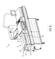
- Fig. 1 shows a Schalenversch separatemaschine invention 1 with a arranged between a discharge device 2 and a feeder 3 Verschmonystation 4.
- the supply and discharge means 3, 2 each comprise a protective device 5, each with a protective cover 6, their positioning in a closed or working position means not shown Sensors are monitored by a machine control 7, so that the tray sealing machine 1 can only be started by an operator when both protective hoods 6 are in the working position. In the working position, the protective covers 6 rest on the machine frame 8 and prevent access to the covered area.
- the protective hoods 6 have a handle 9 on the operating side 10 of the tray closing machine 1 in order to allow manual operation of the protective device 5 or the protective hood 6 itself.
- Fig. 2 shows the tray sealing machine 1 with a raised protective cover 6 at the discharge device 2.
- the protective device 5 at the discharge device 2 comprises the Further, a frame 11, which is arranged on the side of the discharge device 2 on the left in the figure, and extends along the rear side of the tray closing machine 1.
- the protective device 5 covers a portion of a servo-driven conveyor belt 12 which discharges trays from the capping station 4 and the tray closing machine 1.
- the trays are closed with a cover film.
- the protective cover 6 is lifted during the opening process to the extent that the front lower edge 13 of the protective cover 6 is located above the upper edge 14 of the frame 11 in order subsequently to enable a displacement of the protective cover 6 to the rear.
- the lifting operation takes place about a shaft 15, which in the Figures 3 and 4 is shown visible.
- the Fig. 3 shows the tray sealing machine 1 with the protective cover 6, which has been pushed to the rear in the open position.
- the protective cover 6 surrounds with guides 16, which are executed by means of Blechabkantungen in a laterally oriented L or U-shape (as shown), rollers 17 which in FIG. 4 are shown in more detail.
- the rollers 17 are themselves connected to the shaft 15 at the shaft ends and the shaft 15 is mounted on two holders 18 on the frame 11 of the protection device 5. Since the rollers 17 have a rubberized tread with high friction, the sliding movement of the protective cover 6 is synchronized such that the protective hood 6 performs a rearwardly directed rectilinear motion, and thereby run the guides 16 on the rollers 17.
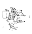
- Fig. 4 shows the Schalenversch separatemaschine 1 with a detached from the guard 5 protective cover 6.
- the two inner guides 16 and a respective recess 21 of the protective hood 6 are shown.
- the protective cover 6 is raised to a removal position, so that the rollers 17 are in the region of the recess 21, and the rollers 17 can get out of the guides 16 out.
- the opening and also the closing movement of the protective cover 6 is defined only by the arrangement and interaction of the shaft 15 together with the two rollers 17 on the frame 11 of the protective device 5 and the guides 18 with the stops 19 of the protective cover 6 ,
- the invention is not limited to a tray closing machine 1, but also extends to a thermoforming packaging machine as well as to transport devices which feed products and discharge packages and together with the packaging machine form a packaging system. All of these devices can have a protective device 5 in one of the variants described here.
- the invention also includes an equivalent embodiment, in which instead of the shaft 15 with the two rollers 17 sliding elements are provided which cooperate in the same way with the protective hood.
- the frame 11 in the production direction of the packaging machine 1 is shorter than the protective cover 6. This causes the front lower edge 13 of the protective cover 6 even with an unintentional lowering of the protective cover 6 on the upper edge 14 of the frame 11 rests (see FIG. 2 ), as soon as the protective cover 6 is pushed backwards by a short distance. In this way, the reliability of the packaging machine 1 is improved because it is prevented by the contact between the edges 13, 14, that the edge 13 of the protective cover 6 comes into contact, for example, with the conveyor belt 2 or trays thereon.
Landscapes
- Engineering & Computer Science (AREA)
- Mechanical Engineering (AREA)
- Auxiliary Devices For And Details Of Packaging Control (AREA)
- Closing Of Containers (AREA)
- Basic Packing Technique (AREA)
Abstract
Description
- Die Erfindung bezieht sich auf eine Verpackungsmaschine mit einer Schutzeinrichtung mit den Merkmalen des Anspruchs 1 sowie auf ein Verfahren zum Betrieb einer Verpackungsmaschine mit den Merkmalen des Anspruchs 9.
- Es sind aus der
WO 2011/154743 , speziell in denFiguren 1 und2 gezeigt, und aus derEP 1996470 B1 , speziellFigur 1 , Schalenverschließmaschinen mit Schutzabdeckungen bekannt, wobei die Schutzabdeckungen um eine horizontale Achse nach oben schwenkbar am Maschinenrahmen vorgesehen sind. Damit kann der abgedeckte Bereich von einer vorderen und hinteren Bedienerseite her für Reinigungs- oder Wartungsarbeiten zugänglich gemacht werden, wobei hierzu an der vorderen und hinteren Bedienerseite jeweils schwenkbare Schutzabdeckung vorhanden sein müssen. Eine Zugänglichkeit von oben ist hierbei nicht gegeben. - Aus der Praxis und
EP 1772384 A1 , speziell in derFigur 3 gezeigt, sind Tiefziehverpackungsmaschinen bekannt, die Schutzabdeckungen aufweisen, die nicht mit dem Maschinenrahmen mechanisch verbunden sind, wobei aber mittels Sensoren ein Vorhandensein der Schutzabdeckung von der Maschinensteuerung überwacht wird. Diese Schutzhauben sind abnehmbar und werden auf den Boden oder anderweitig abseits abgelegt, um den abgedeckten Bereich allseitig für Reinigungs- oder Wartungstätigkeiten zugänglich zu machen. Durch das beliebige Entfernen der Schutzhauben und das willkürliche Ablegen durch das Bedienpersonal kann es zu Beschädigungen an den Schutzhauben kommen und ein passgenaues Wiederauflegen und die folgende Abfrage durch Sensoren kann erschwert oder sogar verhindert werden. Eine mögliche Folge davon ist, dass die Tiefziehverpackungsmaschine nicht mehr gestartet werden kann. Ein weiteres Problem stellt die Gefahr von Verschmutzungen an beispielsweise auf dem Boden abgelegten Schutzhauben dar. Aus Gründen der Hygiene ist dies vor allem im Lebensmittelbereich kritisch oder nicht zulässig. - Aufgabe der vorliegenden Erfindung ist es, eine Schutzeinrichtung für eine Verpackungsmaschine, vorzugsweise für eine Schalenverschließmaschine oder eine Tiefziehverpackungsmaschine, und ein Verfahren zum Betrieb einer Verpackungsmaschine zur Verfügung zu stellen, die eine möglichst einfache Konstruktion einer Schutzeinrichtung und eine gute Zugänglichkeit des Bereiches unter der Schutzeinrichtung ermöglicht.
- Diese Aufgabe wird gelöst durch eine Verpackungsmaschine mit einer Schutzeinrichtung mit den Merkmalen des Anspruchs 1 bzw. durch ein Verfahren zum Betrieb einer solchen Verpackungsmaschine mit den Merkmalen des Anspruchs 9. Vorteilhafte Weiterbildungen der Erfindung sind in den Unteransprüchen angegeben.
- Die erfindungsgemäße Verpackungsmaschine mit einer Schutzeinrichtung, die eine Schutzhaube und einen Rahmen umfasst, zeichnet sich dadurch aus, dass der Rahmen eine Welle mit zwei Rollen und die Schutzhaube Führungen aufweist, wobei die Führungen mit den Rollen derart zusammenwirken, dass die Schutzhaube anhebbar, um die Welle neigbar und verschiebbar ist. Diese konstruktiv einfache und somit kostengünstig herstellbare Schutzeinrichtung führt zu einer sehr guten Zugänglichkeit für den Bediener sowohl seitlich von der Bedienseite der Verpackungsmaschine, als auch von oben. Gleichzeitig bleibt die Schutzhaube mit der Verpackungsmaschine verbunden und kann nicht beschädigt werden.
- Bevorzugt ist die Welle drehbar am Rahmen angebracht. Dabei sind die zwei Rollen bevorzugt mittels der Welle zueinander synchronisiert, um eine geradlinige Bewegung der Schutzhaube zu unterstützen.
- In einer vorteilhaften Ausführung weisen die Rollen eine Lauffläche mit einer derart hohen Friktion auf, dass Gleitreibung entlang der Führungen verhindert wird.
- In einer weiteren bevorzugten Ausführung weisen die Rollen eine Lauffläche mit einer Dämpfung auf, um eine Dämpfungswirkung mit einem Anschlag der Schutzhaube ohne weitere Dämpfungselemente zu ermöglichen.
- Dabei sind die Laufflächen der Rollen vorzugsweise aus einem Elastomer hergestellt, um sowohl eine hohe Friktion aufweisen zu können als auch eine dämpfende Wirkung zu erzielen. Beispielsweise kann es sich bei dem Elastomer um Gummi oder Silikon handeln.
- Bevorzugt ist ein Mittel zur Überwachung der Arbeitsposition der Schutzhaube vorgesehen, um mittels einer Maschinensteuerung einen Produktionsstart erst freizugeben, wenn sich die Schutzhaube in ihrer Arbeitsposition befindet.
- Vorzugsweise ist die Schutzhaube in einer Entnahmeposition schlüssellos von der Schutzeinrichtung abnehmbar, um für besondere Wartungszwecke die Zugänglichkeit auch von der Rückseite der Verpackungsmaschine weiter zu verbessern.
- Das erfindungsgemäße Verfahren zum Betrieb einer Verpackungsmaschine mit einer Schutzeinrichtung zum Bewegen einer Schutzhaube weist folgende Schritte auf:
- Anheben und Neigen der Schutzhaube um eine Welle,
- Verschieben der Schutzhaube entlang Führungen in der Schutzhaube, die auf zwei Rollen der Welle laufen, und
- Neigen der Schutzhaube um die Welle in eine Endlage.
- Der Vorteil liegt in einer einfachen Bedienung der Schutzeinrichtung, indem die Schutzhaube angehoben und nach hinten bzw. quer zu einer Produktionsrichtung geschoben werden kann, um den darunter befindlichen Bereich dem Bedienpersonal für Reinigungs- oder Wartungszwecken möglichst großflächig zugänglich zu machen.
- Vorzugsweise wirken die Rollen als Dämpfer in der Endlage nach dem Verschieben der Schutzhaube, um Schäden und Geräusche beim Erreichen der Endlage zu vermeiden.
- Bevorzugt wird mittels der Welle und den auf der Welle zueinander synchronisierten zwei Rollen ein geradliniges Verschieben der Schutzhaube unterstützt, um für eine solche geradlinige Bewegung keine weiteren Führungseinrichtungen zu benötigen.
- In einer vorteilhaften Ausführung wird die Lage der Schutzhaube in einer Arbeitsposition mittels wenigstens eines Mittels zur Überwachung der Arbeitsposition abgefragt, wobei das Mittel ein Sensor oder ein Schalter sein kann und eine Maschinensteuerung einen Produktionsstart erst freigibt, wenn sich die Schutzhauben in ihrer Arbeitsposition befinden. Das Überwachungsmittel kann berührungslos arbeiten.
- Die Schutzhaube kann bevorzugt in einer Entnahmeposition schlüssellos abgenommen werden.
- Im Folgenden wird ein vorteilhaftes Ausführungsbeispiel der Erfindung anhand einer Zeichnung näher erläutert. Im Einzelnen zeigen:
- Fig. 1
- eine schematische Ansicht einer erfindungsgemäßen Schalenverschließmaschine mit einer Schutzeinrichtung in einer Arbeitsstellung,
- Fig. 2
- eine schematische Ansicht der Schutzeinrichtung in einer angehobenen Stellung,
- Fig. 3
- eine schematische Ansicht der Schutzeinrichtung in einer geöffneten Stellung und
- Fig.4
- eine schematische Ansicht der Schutzeinrichtung mit einer entfernten Schutzhaube.
- Gleiche Komponenten sind in den Figuren durchgängig mit gleichen Bezugszeichen versehen.
-
Fig. 1 zeigt eine erfindungsgemäße Schalenverschließmaschine 1 mit einer zwischen einer Abfuhreinrichtung 2 und einer Zuführeinrichtung 3 angeordneten Verschließstation 4. Die Zuführ- und Abfuhreinrichtung 3, 2 umfassen jeweils eine Schutzeinrichtung 5 mit jeweils einer Schutzabdeckung 6, deren Positionierung in einer geschlossenen bzw. Arbeitsposition mittels nicht näher dargestellter Sensoren von einer Maschinensteuerung 7 überwacht werden, damit die Schalenverschließmaschine 1 von einem Bediener nur gestartet werden kann, wenn sich beide Schutzhauben 6 in der Arbeitsposition befinden. In der Arbeitsposition liegen die Schutzhauben 6 auf dem Maschinenrahmen 8 auf und verhindern einen Zugriff in den abgedeckten Bereich. Die Schutzhauben 6 weisen an der Bedienseite 10 der Schalenverschließmaschine 1 einen Griff 9 auf, um eine manuelle Bedienung der Schutzeinrichtung 5 bzw. der Schutzhaube 6 selbst zu ermöglichen. -
Fig. 2 zeigt die Schalenverschließmaschine 1 mit einer angehobenen Schutzhaube 6 an der Abfuhreinrichtung 2. Die Schutzeinrichtung 5 an der Abfuhreinrichtung 2 umfasst des Weiteren einen Rahmen 11, der sich seitlich, in der Figur links an der Abfuhreinrichtung 2 angeordnet, und entlang der Rückseite der Schalenverschließmaschine 1 erstreckt. Die Schutzeinrichtung 5 sorgt für das Abdecken eines Teilbereichs eines servoangetriebenen Transportbands 12, welches Schalen aus der Verschließstation 4 und der Schalenverschließmaschine 1 abführt. In der Verschließstation 3 werden die Schalen mit einer Deckelfolie verschlossen. Die Schutzhaube 6 wird beim Öffnungsvorgang soweit angehoben, dass die vordere untere Kante 13 der Schutzhaube 6 sich oberhalb der oberen Kante 14 des Rahmens 11 befindet, um im Folgenden ein Verschieben der Schutzhaube 6 nach hinten zu ermöglichen. Der Anhebevorgang erfolgt um eine Welle 15, die in denFiguren 3 und4 sichtbar dargestellt ist. - Die
Fig. 3 zeigt die Schalenverschließmaschine 1 mit der Schutzhaube 6, die nach hinten in die geöffnete Position geschoben wurde. Die Schutzhaube 6 umgreift mit Führungen 16, die mittels Blechabkantungen in einer seitlich orientierten L- oder U-Form (wie gezeigt) ausgeführt sind, Rollen 17, die inFigur 4 näher gezeigt sind. Die Rollen 17 sind selbst mit der Welle 15 an deren Wellenenden verbunden und die Welle 15 ist über zwei Halter 18 am Rahmen 11 der Schutzeinrichtung 5 angebracht. Da die Rollen 17 eine gummierte Lauffläche mit hoher Friktion aufweisen, wird die Schiebebewegung der Schutzhaube 6 derart synchronisiert, dass die Schutzhaube 6 eine nach hinten ausgerichtete geradlinige Bewegung ausführt, und dabei laufen die Führungen 16 auf den Rollen 17. Während dieser Bewegung neigt sich die Schutzhaube 6 kontinuierlich aufgrund der tiefer als die Rahmenoberkante 14 angeordneten Welle 15 bzw. Rollen 17 nach unten. In der inFig. 3 gezeigten Stellung befindet sich die Schutzhaube 6 mit zwei in den Führungen 16 vorgesehenen Anschlägen 19, die inFig. 4 zu gezeigt sind, an den Rollen 17, die aufgrund ihrer gummierten Lauffläche zusätzlich als Dämpfer wirken. Die Halter 18 umfassen jeweils noch eine weitere Gummi- oder Kunststoffrolle 20, die als Anlage für die Schutzhaube 6 in der geöffneten Stellung dient und die Neigung der Schutzhaube 6 somit begrenzt. Die Lage der Schutzhaube 6 in der geöffneten Position wird somit über die Rollen 17 und die Rollen 20 definiert und wird auch als Endlage bezeichnet. Die Rollen 20 müssen nicht drehbar an den Haltern 18 angebracht sein. -
Fig. 4 zeigt die Schalenverschließmaschine 1 mit einer von der Schutzeinrichtung 5 abgenommen Schutzhaube 6. In dieser Ansicht sind die beiden innenliegenden Führungen 16 und jeweils eine Aussparung 21 der Schutzhaube 6 gezeigt. Um die Schutzhaube 6 von den Rollen 17 abnehmen zu können, wird die Schutzhaube 6 in eine Entnahmeposition angehoben, so dass sich die Rollen 17 im Bereich der Aussparung 21 befinden, und die Rollen 17 aus den Führungen 16 heraus gelangen können. Zusammenfassend kann festgestellt werden, dass die Öffnungs- und auch die Schließbewegung der Schutzhaube 6 lediglich durch die Anordnung und Zusammenwirkung der Welle 15 zusammen mit den zwei Rollen 17 am Rahmen 11 der Schutzeinrichtung 5 und den Führungen 18 mit den Anschlägen 19 der Schutzhaube 6 definiert wird. - Die Erfindung ist nicht auf eine Schalenverschließmaschine 1 beschränkt, sondern erstreckt sich auch auf eine Tiefziehverpackungsmaschine sowie auf Transporteinrichtungen, die Produkte zuführen und Verpackungen abführen und mit der Verpackungsmaschine zusammen eine Verpackungsanlage bilden. Alle diese Vorrichtungen können eine Schutzeinrichtung 5 in einer der hier geschilderten Varianten aufweisen.
- Die Erfindung umfasst auch eine äquivalente Ausführung, bei der statt der Welle 15 mit den zwei Rollen 17 Gleitelemente vorgesehen sind, die in gleicher Weise mit der Schutzhaube zusammenwirken.
- Bei dem in den Figuren dargestellten Ausführungsbeispiel ist der Rahmen 11 in Produktionsrichtung der Verpackungsmaschine 1 kürzer als die Schutzhaube 6. Dies führt dazu, dass die vordere untere Kante 13 der Schutzhaube 6 auch bei einem unbeabsichtigten Absenken der Schutzhaube 6 auf der oberen Kante 14 des Rahmens 11 ruht (siehe
Figur 2 ), sobald die Schutzhaube 6 um eine kurze Distanz nach hinten geschoben ist. Auf diese Weise wird die Betriebssicherheit der Verpackungsmaschine 1 verbessert, weil durch den Kontakt zwischen den Kanten 13, 14 verhindert wird, dass die Kante 13 der Schutzhaube 6 beispielsweise mit dem Transportband 2 oder darauf befindlichen Schalen in Kontakt kommt.
Claims (13)
- Verpackungsmaschine (1) mit einer Schutzeinrichtung (5), die eine Schutzhaube (6) und einen Rahmen (11) umfasst, dadurch gekennzeichnet, dass der Rahmen (11) eine Welle (15) mit zwei Rollen (17) und die Schutzhaube (6) Führungen (16) aufweist, wobei die Führungen (16) mit den Rollen (17) derart zusammenwirken, dass die Schutzhaube (6) anhebbar, um die Welle (15) neigbar und verschiebbar ist.
- Verpackungsmaschine nach Anspruch 1, dadurch gekennzeichnet, dass die Welle (15) drehbar am Rahmen (11) angebracht ist.
- Verpackungsmaschine nach Anspruch 2, dadurch gekennzeichnet, dass die zwei Rollen (17) mittels der Welle (15) zueinander synchonisiert sind.
- Verpackungsmaschine nach einem der vorangehenden Ansprüche, dadurch gekennzeichnet, dass die Rollen (17) eine Lauffläche mit einer Friktion aufweisen.
- Verpackungsmaschine nach einem der vorangehenden Ansprüche, dadurch gekennzeichnet, dass die Rollen (17) eine Lauffläche mit einer Dämpfung aufweisen.
- Verpackungsmaschine nach einem der vorangehenden Ansprüche, dadurch gekennzeichnet, dass die Laufflächen der Rollen (17) aus einem Elastomer hergestellt sind.
- Verpackungsmaschine nach einem der vorangehenden Ansprüche, dadurch gekennzeichnet, dass ein Mittel zur Überwachung der Arbeitsposition der Schutzhaube (6) vorgesehen ist.
- Verpackungsmaschine nach einem der vorangehenden Ansprüche, dadurch gekennzeichnet, dass die Schutzhaube (6) in einer Entnahmeposition schlüssellos von der Schutzeinrichtung (5) abnehmbar ist.
- Verfahren zum Betrieb einer Verpackungsmaschine (1) mit einer Schutzeinrichtung (5) zum Bewegen einer Schutzhaube (6), wobei das Verfahren folgende Schritte aufweist:- Anheben und Neigen der Schutzhaube (6) um eine Welle (15),- Verschieben der Schutzhaube (6) entlang Führungen (16) in der Schutzhaube (6), die auf zwei Rollen (17) der Welle (15) laufen, und- Neigen der Schutzhaube (6) um die Welle (15) in eine Endlage.
- Verfahren nach Anspruch 9, dadurch gekennzeichnet, dass die Rollen (17) als Dämpfer in der Endlage nach dem Verschieben der Schutzhaube (6) wirken.
- Verfahren nach einem der Ansprüche 9 oder 10, dadurch gekennzeichnet, dass mittels der Welle (15) und den auf der Welle (15) zueinander synchronisierten zwei Rollen (17) ein geradliniges Verschieben der Schutzhaube (6) unterstützt wird.
- Verfahren nach einem der Ansprüche 9 bis 11, dadurch gekennzeichnet, dass die Schutzhaube (6) in einer Arbeitsposition mittels wenigstens eines Mittels zur Überwachung der Arbeitsposition abgefragt wird.
- Verfahren nach einem der Ansprüche 9 oder 12, dadurch gekennzeichnet, dass die Positionierung der Schutzhaube (6) in einer Entnahmeposition schlüssellos abgenommen werden kann.
Priority Applications (3)
| Application Number | Priority Date | Filing Date | Title |
|---|---|---|---|
| EP12008645.9A EP2749499B1 (de) | 2012-12-28 | 2012-12-28 | Verpackungsmaschine mit einer Schutzeinrichtung und Verfahren |
| ES12008645.9T ES2540998T3 (es) | 2012-12-28 | 2012-12-28 | Máquina de envasado con un dispositivo de protección y procedimiento |
| US14/137,467 US10118784B2 (en) | 2012-12-28 | 2013-12-20 | Packaging machine with a protective device and method |
Applications Claiming Priority (1)
| Application Number | Priority Date | Filing Date | Title |
|---|---|---|---|
| EP12008645.9A EP2749499B1 (de) | 2012-12-28 | 2012-12-28 | Verpackungsmaschine mit einer Schutzeinrichtung und Verfahren |
Publications (2)
| Publication Number | Publication Date |
|---|---|
| EP2749499A1 true EP2749499A1 (de) | 2014-07-02 |
| EP2749499B1 EP2749499B1 (de) | 2015-06-10 |
Family
ID=47522231
Family Applications (1)
| Application Number | Title | Priority Date | Filing Date |
|---|---|---|---|
| EP12008645.9A Not-in-force EP2749499B1 (de) | 2012-12-28 | 2012-12-28 | Verpackungsmaschine mit einer Schutzeinrichtung und Verfahren |
Country Status (3)
| Country | Link |
|---|---|
| US (1) | US10118784B2 (de) |
| EP (1) | EP2749499B1 (de) |
| ES (1) | ES2540998T3 (de) |
Cited By (6)
| Publication number | Priority date | Publication date | Assignee | Title |
|---|---|---|---|---|
| DE102016214417A1 (de) | 2016-08-04 | 2018-02-08 | Multivac Sepp Haggenmüller Se & Co. Kg | Verpackungsmaschine mit Haltevorrichtung für Schutzabdeckung |
| EP3381820A1 (de) * | 2017-03-30 | 2018-10-03 | MULTIVAC Sepp Haggenmüller SE & Co. KG | Verpackungsmaschine mit stapelbaren schutzabdeckungen |
| EP3483494A1 (de) * | 2017-11-13 | 2019-05-15 | MULTIVAC Sepp Haggenmüller SE & Co. KG | Verpackungsmaschine mit an schutzabdeckung angeordneter tokenbefestigungskapsel sowie verfahren |
| EP3492398A1 (de) * | 2017-11-30 | 2019-06-05 | MULTIVAC Sepp Haggenmüller SE & Co. KG | Verpackungsmaschine mit aufklappbarer schutzabdeckung |
| EP3501997A1 (de) * | 2017-12-21 | 2019-06-26 | MULTIVAC Sepp Haggenmüller SE & Co. KG | Aufbewahrungswagen für schutzabdeckungen |
| DE102018204049A1 (de) * | 2018-03-16 | 2019-09-19 | Multivac Sepp Haggenmüller Se & Co. Kg | Verpackungsmaschine mit kombiniertem Kontaminations- und Eingriffsschutz |
Families Citing this family (3)
| Publication number | Priority date | Publication date | Assignee | Title |
|---|---|---|---|---|
| US20170210497A1 (en) * | 2014-07-23 | 2017-07-27 | Gruppo Fabbri Vignola S.P.A. | Machine for packaging products with stretch film |
| CN104691850B (zh) * | 2015-02-13 | 2016-05-25 | 安硕文教用品(上海)股份有限公司 | 一种吸塑包装机械 |
| DE102023108600A1 (de) * | 2023-04-04 | 2024-10-10 | Multivac Sepp Haggenmüller Se & Co. Kg | Abdecksystem, Verwendung sowie Verfahren |
Citations (7)
| Publication number | Priority date | Publication date | Assignee | Title |
|---|---|---|---|---|
| DE8623122U1 (de) * | 1986-08-28 | 1987-01-08 | Krämer + Grebe GmbH & Co KG Maschinenfabrik, 3560 Biedenkopf | Sicherheitseinrichtung für Verpackungsmaschinen |
| EP0483446A1 (de) * | 1990-10-27 | 1992-05-06 | Krämer + Grebe GmbH & Co. KG Maschinenfabrik | Schutzvorrichtung an einer Verpackungsmaschine |
| DE19920260A1 (de) * | 1999-05-04 | 2000-11-09 | Hajek Ges M B H & Co Maschbau | Vakuum-Tiefziehverpackungsmaschine |
| EP1772384A1 (de) | 2005-10-07 | 2007-04-11 | VARIOVAC PS SystemPack GmbH | Maschine und Verfahren zur Herstellung von Mehrlagenfolienverpackungen |
| DE102008053665A1 (de) * | 2008-10-29 | 2010-05-12 | Multivac Sepp Haggenmüller Gmbh & Co. Kg | Verpackungsmaschine mit hygienischer Haube |
| EP1996470B1 (de) | 2006-03-17 | 2011-07-06 | Ishida Europe Limited | Greiferanordnung für schalenverschlussmaschine |
| WO2011154743A1 (en) | 2010-06-11 | 2011-12-15 | Ishida Europe Limited | Tray sealing apparatus and method |
Family Cites Families (7)
| Publication number | Priority date | Publication date | Assignee | Title |
|---|---|---|---|---|
| US2338477A (en) * | 1941-06-24 | 1944-01-04 | Remington Rand Inc | Filing cabinet |
| CH266698A (fr) * | 1947-12-24 | 1950-02-15 | Bechler Andre | Dispositif de protection contre huile et copeaux pour tour automatique à décolleter. |
| US3525177A (en) * | 1969-04-14 | 1970-08-25 | Honeywell Inc | Readily removable door for instrument casing |
| US3693318A (en) * | 1970-08-26 | 1972-09-26 | Winton E Balzer | Tray covering and sealing apparatus |
| US20010017021A1 (en) * | 1997-07-02 | 2001-08-30 | James J. Sanfilippo | Apparatus system and method for exposing product filled containers transported via an intermittent conveyer to a controlled environment |
| DE102008023319B4 (de) * | 2008-05-13 | 2014-05-28 | Multivac Sepp Haggenmüller Gmbh & Co. Kg | Verpackungsmaschine mit einem spindeltrieb-hubwerk |
| DE102011101051A1 (de) * | 2011-05-10 | 2012-11-15 | Multivac Sepp Haggenmüller Gmbh & Co. Kg | Werkzeugwechseleinrichtung |
-
2012
- 2012-12-28 ES ES12008645.9T patent/ES2540998T3/es active Active
- 2012-12-28 EP EP12008645.9A patent/EP2749499B1/de not_active Not-in-force
-
2013
- 2013-12-20 US US14/137,467 patent/US10118784B2/en active Active
Patent Citations (7)
| Publication number | Priority date | Publication date | Assignee | Title |
|---|---|---|---|---|
| DE8623122U1 (de) * | 1986-08-28 | 1987-01-08 | Krämer + Grebe GmbH & Co KG Maschinenfabrik, 3560 Biedenkopf | Sicherheitseinrichtung für Verpackungsmaschinen |
| EP0483446A1 (de) * | 1990-10-27 | 1992-05-06 | Krämer + Grebe GmbH & Co. KG Maschinenfabrik | Schutzvorrichtung an einer Verpackungsmaschine |
| DE19920260A1 (de) * | 1999-05-04 | 2000-11-09 | Hajek Ges M B H & Co Maschbau | Vakuum-Tiefziehverpackungsmaschine |
| EP1772384A1 (de) | 2005-10-07 | 2007-04-11 | VARIOVAC PS SystemPack GmbH | Maschine und Verfahren zur Herstellung von Mehrlagenfolienverpackungen |
| EP1996470B1 (de) | 2006-03-17 | 2011-07-06 | Ishida Europe Limited | Greiferanordnung für schalenverschlussmaschine |
| DE102008053665A1 (de) * | 2008-10-29 | 2010-05-12 | Multivac Sepp Haggenmüller Gmbh & Co. Kg | Verpackungsmaschine mit hygienischer Haube |
| WO2011154743A1 (en) | 2010-06-11 | 2011-12-15 | Ishida Europe Limited | Tray sealing apparatus and method |
Cited By (13)
| Publication number | Priority date | Publication date | Assignee | Title |
|---|---|---|---|---|
| DE102016214417A1 (de) | 2016-08-04 | 2018-02-08 | Multivac Sepp Haggenmüller Se & Co. Kg | Verpackungsmaschine mit Haltevorrichtung für Schutzabdeckung |
| EP3381820A1 (de) * | 2017-03-30 | 2018-10-03 | MULTIVAC Sepp Haggenmüller SE & Co. KG | Verpackungsmaschine mit stapelbaren schutzabdeckungen |
| DE102017106898A1 (de) | 2017-03-30 | 2018-10-04 | Multivac Sepp Haggenmüller Se & Co. Kg | Verpackungsmaschine mit stapelbaren Schutzabdeckungen |
| DE102017106898B4 (de) | 2017-03-30 | 2023-03-02 | Multivac Sepp Haggenmüller Se & Co. Kg | Verpackungsmaschine mit stapelbaren Schutzabdeckungen |
| US10899486B2 (en) | 2017-03-30 | 2021-01-26 | Multivac Sepp Haggenmüller Se & Co. Kg | Packaging machine with stackable protective covers |
| US10882653B2 (en) | 2017-11-13 | 2021-01-05 | Multivac Sepp Haggenmueller Se & Co. Kg | Packaging machine with a protective cover, a token fastening capsule arranged thereon as well as a method |
| EP3483494A1 (de) * | 2017-11-13 | 2019-05-15 | MULTIVAC Sepp Haggenmüller SE & Co. KG | Verpackungsmaschine mit an schutzabdeckung angeordneter tokenbefestigungskapsel sowie verfahren |
| DE102017128363A1 (de) | 2017-11-30 | 2019-06-06 | Multivac Sepp Haggenmüller Se & Co. Kg | Verpackungsmaschine mit aufklappbarer schutzabdeckung |
| EP3492398A1 (de) * | 2017-11-30 | 2019-06-05 | MULTIVAC Sepp Haggenmüller SE & Co. KG | Verpackungsmaschine mit aufklappbarer schutzabdeckung |
| US10906681B2 (en) | 2017-11-30 | 2021-02-02 | Multivac Sepp Haggenmueller Se & Co. Kg | Packaging machine with hinged protective cover |
| EP3501997A1 (de) * | 2017-12-21 | 2019-06-26 | MULTIVAC Sepp Haggenmüller SE & Co. KG | Aufbewahrungswagen für schutzabdeckungen |
| DE102018204049A1 (de) * | 2018-03-16 | 2019-09-19 | Multivac Sepp Haggenmüller Se & Co. Kg | Verpackungsmaschine mit kombiniertem Kontaminations- und Eingriffsschutz |
| DE102018204049B4 (de) * | 2018-03-16 | 2020-10-22 | Multivac Sepp Haggenmüller Se & Co. Kg | Verpackungsmaschine mit kombiniertem Kontaminations- und Eingriffsschutz |
Also Published As
| Publication number | Publication date |
|---|---|
| EP2749499B1 (de) | 2015-06-10 |
| US10118784B2 (en) | 2018-11-06 |
| ES2540998T3 (es) | 2015-07-15 |
| US20140182246A1 (en) | 2014-07-03 |
Similar Documents
| Publication | Publication Date | Title |
|---|---|---|
| EP2749499B1 (de) | Verpackungsmaschine mit einer Schutzeinrichtung und Verfahren | |
| EP2623441B1 (de) | Speichervorrichtung für Behälter und Verfahren zum Speichern von Behältern | |
| DE19518583C2 (de) | Schneidmaschine zum Zerschneiden von Produktlaiben | |
| EP0635340B1 (de) | Schneidautomat | |
| EP0379019A1 (de) | Auf einem horizontal verfahrbaren Einschubwagen angeordnete Platteneinschubvorrichtung | |
| EP4082924B1 (de) | Siegelmaschine zum versiegeln von verpackungen | |
| EP3124387B1 (de) | Tiefziehverpackungsmaschine | |
| EP2776347B1 (de) | Beschickungsvorrichtung für behälterverschlüsse | |
| EP0694019B1 (de) | Vorrichtung zum ablösen eines produktes von einem endlos umlaufenden band | |
| DE1202620B (de) | Vorfuehr- und Austragvorrichtung fuer plattenfoermige Werkstuecke | |
| EP3088315B2 (de) | Tiefziehverpackungsmaschine mit streifenstanze | |
| DE3627038A1 (de) | Einrichtung zum zerkleinern von grossformatigen kuehlgutbloecken u.dgl., insbesondere fuer die tierfutterherstellung | |
| EP2995441B1 (de) | Tiefziehverpackungsmaschine mit hubeinrichtung und verfahren | |
| EP2481540B1 (de) | Einrichtung zum Zersägen von zumindest zwei platten- oder plattenstapelförmigen Werkstücken | |
| DE202008013659U1 (de) | Verpackungsmaschine mit Schneidmesser | |
| EP0436081A1 (de) | Fördereinrichtung | |
| CH396764A (de) | Einrichtung zur Entnahme von auf einem laufenden Förderband befindlichem Stückgut | |
| EP0483446A1 (de) | Schutzvorrichtung an einer Verpackungsmaschine | |
| EP3722057A1 (de) | Aufschneiden von lebensmittelprodukten | |
| EP3649863A1 (de) | Austragsvorrichtung für kompakte nahrungsmittelmassen, insbesondere riegelmassen oder keksteige | |
| EP2644517B1 (de) | Mehrreihige Siegelstation, entsprechende Verpackungsmaschine und entsprechendes Verfahren | |
| EP3715286B1 (de) | Verstellbarer einklemmschutz für gurtförderer | |
| DE2142502A1 (de) | Ladevorrichtung, insbesondere für die Zufuhr von Schraubenrohlingen u. dgl. zu einer Arbeitsmaschine | |
| DE4035641A1 (de) | Abschwartmaschine | |
| DE2222694A1 (de) | Holzschneidemaschine |
Legal Events
| Date | Code | Title | Description |
|---|---|---|---|
| 17P | Request for examination filed |
Effective date: 20121228 |
|
| AK | Designated contracting states |
Kind code of ref document: A1 Designated state(s): AL AT BE BG CH CY CZ DE DK EE ES FI FR GB GR HR HU IE IS IT LI LT LU LV MC MK MT NL NO PL PT RO RS SE SI SK SM TR |
|
| AX | Request for extension of the european patent |
Extension state: BA ME |
|
| PUAI | Public reference made under article 153(3) epc to a published international application that has entered the european phase |
Free format text: ORIGINAL CODE: 0009012 |
|
| R17P | Request for examination filed (corrected) |
Effective date: 20140728 |
|
| RBV | Designated contracting states (corrected) |
Designated state(s): AL AT BE BG CH CY CZ DE DK EE ES FI FR GB GR HR HU IE IS IT LI LT LU LV MC MK MT NL NO PL PT RO RS SE SI SK SM TR |
|
| GRAP | Despatch of communication of intention to grant a patent |
Free format text: ORIGINAL CODE: EPIDOSNIGR1 |
|
| RIC1 | Information provided on ipc code assigned before grant |
Ipc: B65H 20/02 20060101ALI20141024BHEP Ipc: B65B 57/00 20060101AFI20141024BHEP Ipc: F16P 1/02 20060101ALI20141024BHEP Ipc: B65B 7/16 20060101ALI20141024BHEP |
|
| INTG | Intention to grant announced |
Effective date: 20141118 |
|
| GRAP | Despatch of communication of intention to grant a patent |
Free format text: ORIGINAL CODE: EPIDOSNIGR1 |
|
| RIC1 | Information provided on ipc code assigned before grant |
Ipc: B65B 47/00 20060101ALI20150211BHEP Ipc: B65B 7/16 20060101ALI20150211BHEP Ipc: B65B 57/00 20060101AFI20150211BHEP Ipc: B65H 20/02 20060101ALI20150211BHEP Ipc: F16P 1/02 20060101ALI20150211BHEP |
|
| INTG | Intention to grant announced |
Effective date: 20150227 |
|
| GRAS | Grant fee paid |
Free format text: ORIGINAL CODE: EPIDOSNIGR3 |
|
| GRAA | (expected) grant |
Free format text: ORIGINAL CODE: 0009210 |
|
| AK | Designated contracting states |
Kind code of ref document: B1 Designated state(s): AL AT BE BG CH CY CZ DE DK EE ES FI FR GB GR HR HU IE IS IT LI LT LU LV MC MK MT NL NO PL PT RO RS SE SI SK SM TR |
|
| REG | Reference to a national code |
Ref country code: GB Ref legal event code: FG4D Free format text: NOT ENGLISH |
|
| REG | Reference to a national code |
Ref country code: CH Ref legal event code: NV Representative=s name: BOVARD AG, CH Ref country code: CH Ref legal event code: EP |
|
| REG | Reference to a national code |
Ref country code: AT Ref legal event code: REF Ref document number: 730796 Country of ref document: AT Kind code of ref document: T Effective date: 20150715 Ref country code: ES Ref legal event code: FG2A Ref document number: 2540998 Country of ref document: ES Kind code of ref document: T3 Effective date: 20150715 |
|
| REG | Reference to a national code |
Ref country code: DE Ref legal event code: R096 Ref document number: 502012003392 Country of ref document: DE |
|
| REG | Reference to a national code |
Ref country code: IE Ref legal event code: FG4D Free format text: LANGUAGE OF EP DOCUMENT: GERMAN |
|
| PG25 | Lapsed in a contracting state [announced via postgrant information from national office to epo] |
Ref country code: FI Free format text: LAPSE BECAUSE OF FAILURE TO SUBMIT A TRANSLATION OF THE DESCRIPTION OR TO PAY THE FEE WITHIN THE PRESCRIBED TIME-LIMIT Effective date: 20150610 Ref country code: LT Free format text: LAPSE BECAUSE OF FAILURE TO SUBMIT A TRANSLATION OF THE DESCRIPTION OR TO PAY THE FEE WITHIN THE PRESCRIBED TIME-LIMIT Effective date: 20150610 Ref country code: NO Free format text: LAPSE BECAUSE OF FAILURE TO SUBMIT A TRANSLATION OF THE DESCRIPTION OR TO PAY THE FEE WITHIN THE PRESCRIBED TIME-LIMIT Effective date: 20150910 |
|
| REG | Reference to a national code |
Ref country code: NL Ref legal event code: MP Effective date: 20150610 |
|
| PG25 | Lapsed in a contracting state [announced via postgrant information from national office to epo] |
Ref country code: RS Free format text: LAPSE BECAUSE OF FAILURE TO SUBMIT A TRANSLATION OF THE DESCRIPTION OR TO PAY THE FEE WITHIN THE PRESCRIBED TIME-LIMIT Effective date: 20150610 Ref country code: BG Free format text: LAPSE BECAUSE OF FAILURE TO SUBMIT A TRANSLATION OF THE DESCRIPTION OR TO PAY THE FEE WITHIN THE PRESCRIBED TIME-LIMIT Effective date: 20150910 Ref country code: LV Free format text: LAPSE BECAUSE OF FAILURE TO SUBMIT A TRANSLATION OF THE DESCRIPTION OR TO PAY THE FEE WITHIN THE PRESCRIBED TIME-LIMIT Effective date: 20150610 Ref country code: GR Free format text: LAPSE BECAUSE OF FAILURE TO SUBMIT A TRANSLATION OF THE DESCRIPTION OR TO PAY THE FEE WITHIN THE PRESCRIBED TIME-LIMIT Effective date: 20150911 |
|
| REG | Reference to a national code |
Ref country code: FR Ref legal event code: PLFP Year of fee payment: 4 |
|
| PG25 | Lapsed in a contracting state [announced via postgrant information from national office to epo] |
Ref country code: EE Free format text: LAPSE BECAUSE OF FAILURE TO SUBMIT A TRANSLATION OF THE DESCRIPTION OR TO PAY THE FEE WITHIN THE PRESCRIBED TIME-LIMIT Effective date: 20150610 |
|
| PG25 | Lapsed in a contracting state [announced via postgrant information from national office to epo] |
Ref country code: IS Free format text: LAPSE BECAUSE OF FAILURE TO SUBMIT A TRANSLATION OF THE DESCRIPTION OR TO PAY THE FEE WITHIN THE PRESCRIBED TIME-LIMIT Effective date: 20151010 Ref country code: CZ Free format text: LAPSE BECAUSE OF FAILURE TO SUBMIT A TRANSLATION OF THE DESCRIPTION OR TO PAY THE FEE WITHIN THE PRESCRIBED TIME-LIMIT Effective date: 20150610 Ref country code: RO Free format text: LAPSE BECAUSE OF NON-PAYMENT OF DUE FEES Effective date: 20150610 Ref country code: SK Free format text: LAPSE BECAUSE OF FAILURE TO SUBMIT A TRANSLATION OF THE DESCRIPTION OR TO PAY THE FEE WITHIN THE PRESCRIBED TIME-LIMIT Effective date: 20150610 Ref country code: PT Free format text: LAPSE BECAUSE OF FAILURE TO SUBMIT A TRANSLATION OF THE DESCRIPTION OR TO PAY THE FEE WITHIN THE PRESCRIBED TIME-LIMIT Effective date: 20151012 Ref country code: PL Free format text: LAPSE BECAUSE OF FAILURE TO SUBMIT A TRANSLATION OF THE DESCRIPTION OR TO PAY THE FEE WITHIN THE PRESCRIBED TIME-LIMIT Effective date: 20150610 |
|
| REG | Reference to a national code |
Ref country code: DE Ref legal event code: R097 Ref document number: 502012003392 Country of ref document: DE |
|
| REG | Reference to a national code |
Ref country code: DE Ref legal event code: R082 Ref document number: 502012003392 Country of ref document: DE Representative=s name: GRUENECKER PATENT- UND RECHTSANWAELTE PARTG MB, DE Ref country code: DE Ref legal event code: R081 Ref document number: 502012003392 Country of ref document: DE Owner name: MULTIVAC SEPP HAGGENMUELLER SE & CO. KG, DE Free format text: FORMER OWNER: MULTIVAC SEPP HAGGENMUELLER GMBH & CO. KG, 87787 WOLFERTSCHWENDEN, DE |
|
| PLBE | No opposition filed within time limit |
Free format text: ORIGINAL CODE: 0009261 |
|
| STAA | Information on the status of an ep patent application or granted ep patent |
Free format text: STATUS: NO OPPOSITION FILED WITHIN TIME LIMIT |
|
| PG25 | Lapsed in a contracting state [announced via postgrant information from national office to epo] |
Ref country code: DK Free format text: LAPSE BECAUSE OF FAILURE TO SUBMIT A TRANSLATION OF THE DESCRIPTION OR TO PAY THE FEE WITHIN THE PRESCRIBED TIME-LIMIT Effective date: 20150610 |
|
| 26N | No opposition filed |
Effective date: 20160311 |
|
| PG25 | Lapsed in a contracting state [announced via postgrant information from national office to epo] |
Ref country code: BE Free format text: LAPSE BECAUSE OF NON-PAYMENT OF DUE FEES Effective date: 20151231 Ref country code: SI Free format text: LAPSE BECAUSE OF FAILURE TO SUBMIT A TRANSLATION OF THE DESCRIPTION OR TO PAY THE FEE WITHIN THE PRESCRIBED TIME-LIMIT Effective date: 20150610 |
|
| PG25 | Lapsed in a contracting state [announced via postgrant information from national office to epo] |
Ref country code: LU Free format text: LAPSE BECAUSE OF FAILURE TO SUBMIT A TRANSLATION OF THE DESCRIPTION OR TO PAY THE FEE WITHIN THE PRESCRIBED TIME-LIMIT Effective date: 20151228 Ref country code: MC Free format text: LAPSE BECAUSE OF FAILURE TO SUBMIT A TRANSLATION OF THE DESCRIPTION OR TO PAY THE FEE WITHIN THE PRESCRIBED TIME-LIMIT Effective date: 20150610 |
|
| REG | Reference to a national code |
Ref country code: IE Ref legal event code: MM4A |
|
| PG25 | Lapsed in a contracting state [announced via postgrant information from national office to epo] |
Ref country code: IE Free format text: LAPSE BECAUSE OF NON-PAYMENT OF DUE FEES Effective date: 20151228 |
|
| REG | Reference to a national code |
Ref country code: FR Ref legal event code: PLFP Year of fee payment: 5 |
|
| PG25 | Lapsed in a contracting state [announced via postgrant information from national office to epo] |
Ref country code: HU Free format text: LAPSE BECAUSE OF FAILURE TO SUBMIT A TRANSLATION OF THE DESCRIPTION OR TO PAY THE FEE WITHIN THE PRESCRIBED TIME-LIMIT; INVALID AB INITIO Effective date: 20121228 Ref country code: SM Free format text: LAPSE BECAUSE OF FAILURE TO SUBMIT A TRANSLATION OF THE DESCRIPTION OR TO PAY THE FEE WITHIN THE PRESCRIBED TIME-LIMIT Effective date: 20150610 |
|
| PG25 | Lapsed in a contracting state [announced via postgrant information from national office to epo] |
Ref country code: CY Free format text: LAPSE BECAUSE OF FAILURE TO SUBMIT A TRANSLATION OF THE DESCRIPTION OR TO PAY THE FEE WITHIN THE PRESCRIBED TIME-LIMIT Effective date: 20150610 Ref country code: SE Free format text: LAPSE BECAUSE OF FAILURE TO SUBMIT A TRANSLATION OF THE DESCRIPTION OR TO PAY THE FEE WITHIN THE PRESCRIBED TIME-LIMIT Effective date: 20150610 Ref country code: NL Free format text: LAPSE BECAUSE OF FAILURE TO SUBMIT A TRANSLATION OF THE DESCRIPTION OR TO PAY THE FEE WITHIN THE PRESCRIBED TIME-LIMIT Effective date: 20150610 |
|
| PG25 | Lapsed in a contracting state [announced via postgrant information from national office to epo] |
Ref country code: HR Free format text: LAPSE BECAUSE OF FAILURE TO SUBMIT A TRANSLATION OF THE DESCRIPTION OR TO PAY THE FEE WITHIN THE PRESCRIBED TIME-LIMIT Effective date: 20150610 |
|
| PG25 | Lapsed in a contracting state [announced via postgrant information from national office to epo] |
Ref country code: MT Free format text: LAPSE BECAUSE OF FAILURE TO SUBMIT A TRANSLATION OF THE DESCRIPTION OR TO PAY THE FEE WITHIN THE PRESCRIBED TIME-LIMIT Effective date: 20150610 |
|
| REG | Reference to a national code |
Ref country code: FR Ref legal event code: PLFP Year of fee payment: 6 |
|
| PG25 | Lapsed in a contracting state [announced via postgrant information from national office to epo] |
Ref country code: MK Free format text: LAPSE BECAUSE OF FAILURE TO SUBMIT A TRANSLATION OF THE DESCRIPTION OR TO PAY THE FEE WITHIN THE PRESCRIBED TIME-LIMIT Effective date: 20150610 |
|
| PG25 | Lapsed in a contracting state [announced via postgrant information from national office to epo] |
Ref country code: AL Free format text: LAPSE BECAUSE OF FAILURE TO SUBMIT A TRANSLATION OF THE DESCRIPTION OR TO PAY THE FEE WITHIN THE PRESCRIBED TIME-LIMIT Effective date: 20150610 |
|
| REG | Reference to a national code |
Ref country code: AT Ref legal event code: MM01 Ref document number: 730796 Country of ref document: AT Kind code of ref document: T Effective date: 20171228 |
|
| PG25 | Lapsed in a contracting state [announced via postgrant information from national office to epo] |
Ref country code: AT Free format text: LAPSE BECAUSE OF NON-PAYMENT OF DUE FEES Effective date: 20171228 |
|
| PGFP | Annual fee paid to national office [announced via postgrant information from national office to epo] |
Ref country code: FR Payment date: 20211220 Year of fee payment: 10 |
|
| PGFP | Annual fee paid to national office [announced via postgrant information from national office to epo] |
Ref country code: CH Payment date: 20211222 Year of fee payment: 10 |
|
| PGFP | Annual fee paid to national office [announced via postgrant information from national office to epo] |
Ref country code: TR Payment date: 20211223 Year of fee payment: 10 |
|
| PGFP | Annual fee paid to national office [announced via postgrant information from national office to epo] |
Ref country code: GB Payment date: 20221222 Year of fee payment: 11 |
|
| PGFP | Annual fee paid to national office [announced via postgrant information from national office to epo] |
Ref country code: ES Payment date: 20230119 Year of fee payment: 11 |
|
| PGFP | Annual fee paid to national office [announced via postgrant information from national office to epo] |
Ref country code: IT Payment date: 20221230 Year of fee payment: 11 Ref country code: DE Payment date: 20221221 Year of fee payment: 11 |
|
| P01 | Opt-out of the competence of the unified patent court (upc) registered |
Effective date: 20230404 |
|
| REG | Reference to a national code |
Ref country code: CH Ref legal event code: PL |
|
| PG25 | Lapsed in a contracting state [announced via postgrant information from national office to epo] |
Ref country code: LI Free format text: LAPSE BECAUSE OF NON-PAYMENT OF DUE FEES Effective date: 20221231 Ref country code: CH Free format text: LAPSE BECAUSE OF NON-PAYMENT OF DUE FEES Effective date: 20221231 |
|
| PG25 | Lapsed in a contracting state [announced via postgrant information from national office to epo] |
Ref country code: FR Free format text: LAPSE BECAUSE OF NON-PAYMENT OF DUE FEES Effective date: 20221231 |
|
| REG | Reference to a national code |
Ref country code: DE Ref legal event code: R119 Ref document number: 502012003392 Country of ref document: DE |
|
| GBPC | Gb: european patent ceased through non-payment of renewal fee |
Effective date: 20231228 |
|
| PG25 | Lapsed in a contracting state [announced via postgrant information from national office to epo] |
Ref country code: TR Free format text: LAPSE BECAUSE OF NON-PAYMENT OF DUE FEES Effective date: 20221228 |
|
| PG25 | Lapsed in a contracting state [announced via postgrant information from national office to epo] |
Ref country code: DE Free format text: LAPSE BECAUSE OF NON-PAYMENT OF DUE FEES Effective date: 20240702 |
|
| PG25 | Lapsed in a contracting state [announced via postgrant information from national office to epo] |
Ref country code: GB Free format text: LAPSE BECAUSE OF NON-PAYMENT OF DUE FEES Effective date: 20231228 |
|
| PG25 | Lapsed in a contracting state [announced via postgrant information from national office to epo] |
Ref country code: GB Free format text: LAPSE BECAUSE OF NON-PAYMENT OF DUE FEES Effective date: 20231228 Ref country code: DE Free format text: LAPSE BECAUSE OF NON-PAYMENT OF DUE FEES Effective date: 20240702 |
|
| REG | Reference to a national code |
Ref country code: ES Ref legal event code: FD2A Effective date: 20250206 |
|
| PG25 | Lapsed in a contracting state [announced via postgrant information from national office to epo] |
Ref country code: ES Free format text: LAPSE BECAUSE OF NON-PAYMENT OF DUE FEES Effective date: 20231229 |
|
| PG25 | Lapsed in a contracting state [announced via postgrant information from national office to epo] |
Ref country code: IT Free format text: LAPSE BECAUSE OF NON-PAYMENT OF DUE FEES Effective date: 20231228 |