EP2749336B1 - Wasserfiltervorrichtung mit Verschlüsselungsstruktur - Google Patents
Wasserfiltervorrichtung mit Verschlüsselungsstruktur Download PDFInfo
- Publication number
- EP2749336B1 EP2749336B1 EP14000356.7A EP14000356A EP2749336B1 EP 2749336 B1 EP2749336 B1 EP 2749336B1 EP 14000356 A EP14000356 A EP 14000356A EP 2749336 B1 EP2749336 B1 EP 2749336B1
- Authority
- EP
- European Patent Office
- Prior art keywords
- filter
- water
- filter cartridge
- valve
- filter device
- Prior art date
- Legal status (The legal status is an assumption and is not a legal conclusion. Google has not performed a legal analysis and makes no representation as to the accuracy of the status listed.)
- Active
Links
Images

Classifications
-
- B—PERFORMING OPERATIONS; TRANSPORTING
- B01—PHYSICAL OR CHEMICAL PROCESSES OR APPARATUS IN GENERAL
- B01D—SEPARATION
- B01D29/00—Filters with filtering elements stationary during filtration, e.g. pressure or suction filters, not covered by groups B01D24/00 - B01D27/00; Filtering elements therefor
- B01D29/11—Filters with filtering elements stationary during filtration, e.g. pressure or suction filters, not covered by groups B01D24/00 - B01D27/00; Filtering elements therefor with bag, cage, hose, tube, sleeve or like filtering elements
-
- C—CHEMISTRY; METALLURGY
- C02—TREATMENT OF WATER, WASTE WATER, SEWAGE, OR SLUDGE
- C02F—TREATMENT OF WATER, WASTE WATER, SEWAGE, OR SLUDGE
- C02F1/00—Treatment of water, waste water, or sewage
- C02F1/001—Processes for the treatment of water whereby the filtration technique is of importance
- C02F1/003—Processes for the treatment of water whereby the filtration technique is of importance using household-type filters for producing potable water, e.g. pitchers, bottles, faucet mounted devices
-
- B—PERFORMING OPERATIONS; TRANSPORTING
- B01—PHYSICAL OR CHEMICAL PROCESSES OR APPARATUS IN GENERAL
- B01D—SEPARATION
- B01D35/00—Filtering devices having features not specifically covered by groups B01D24/00 - B01D33/00, or for applications not specifically covered by groups B01D24/00 - B01D33/00; Auxiliary devices for filtration; Filter housing constructions
- B01D35/14—Safety devices specially adapted for filtration; Devices for indicating clogging
- B01D35/147—Bypass or safety valves
-
- C—CHEMISTRY; METALLURGY
- C02—TREATMENT OF WATER, WASTE WATER, SEWAGE, OR SLUDGE
- C02F—TREATMENT OF WATER, WASTE WATER, SEWAGE, OR SLUDGE
- C02F1/00—Treatment of water, waste water, or sewage
-
- C—CHEMISTRY; METALLURGY
- C02—TREATMENT OF WATER, WASTE WATER, SEWAGE, OR SLUDGE
- C02F—TREATMENT OF WATER, WASTE WATER, SEWAGE, OR SLUDGE
- C02F9/00—Multistage treatment of water, waste water or sewage
- C02F9/20—Portable or detachable small-scale multistage treatment devices, e.g. point of use or laboratory water purification systems
-
- B—PERFORMING OPERATIONS; TRANSPORTING
- B01—PHYSICAL OR CHEMICAL PROCESSES OR APPARATUS IN GENERAL
- B01D—SEPARATION
- B01D2201/00—Details relating to filtering apparatus
- B01D2201/16—Valves
-
- B—PERFORMING OPERATIONS; TRANSPORTING
- B01—PHYSICAL OR CHEMICAL PROCESSES OR APPARATUS IN GENERAL
- B01D—SEPARATION
- B01D2201/00—Details relating to filtering apparatus
- B01D2201/30—Filter housing constructions
- B01D2201/301—Details of removable closures, lids, caps, filter heads
- B01D2201/302—Details of removable closures, lids, caps, filter heads having inlet or outlet ports
-
- B—PERFORMING OPERATIONS; TRANSPORTING
- B01—PHYSICAL OR CHEMICAL PROCESSES OR APPARATUS IN GENERAL
- B01D—SEPARATION
- B01D2201/00—Details relating to filtering apparatus
- B01D2201/40—Special measures for connecting different parts of the filter
- B01D2201/4046—Means for avoiding false mounting of different parts
-
- C—CHEMISTRY; METALLURGY
- C02—TREATMENT OF WATER, WASTE WATER, SEWAGE, OR SLUDGE
- C02F—TREATMENT OF WATER, WASTE WATER, SEWAGE, OR SLUDGE
- C02F2201/00—Apparatus for treatment of water, waste water or sewage
- C02F2201/002—Construction details of the apparatus
-
- C—CHEMISTRY; METALLURGY
- C02—TREATMENT OF WATER, WASTE WATER, SEWAGE, OR SLUDGE
- C02F—TREATMENT OF WATER, WASTE WATER, SEWAGE, OR SLUDGE
- C02F2201/00—Apparatus for treatment of water, waste water or sewage
- C02F2201/002—Construction details of the apparatus
- C02F2201/003—Coaxial constructions, e.g. a cartridge located coaxially within another
-
- C—CHEMISTRY; METALLURGY
- C02—TREATMENT OF WATER, WASTE WATER, SEWAGE, OR SLUDGE
- C02F—TREATMENT OF WATER, WASTE WATER, SEWAGE, OR SLUDGE
- C02F2201/00—Apparatus for treatment of water, waste water or sewage
- C02F2201/002—Construction details of the apparatus
- C02F2201/006—Cartridges
-
- C—CHEMISTRY; METALLURGY
- C02—TREATMENT OF WATER, WASTE WATER, SEWAGE, OR SLUDGE
- C02F—TREATMENT OF WATER, WASTE WATER, SEWAGE, OR SLUDGE
- C02F2301/00—General aspects of water treatment
- C02F2301/04—Flow arrangements
- C02F2301/043—Treatment of partial or bypass streams
Definitions
- the present invention relates to a water filter device according to the preamble of claim 1.
- such water filter devices consist of a filter head and its associated filter head components and a replaceable filter cartridge with its associated filter cartridge components.
- an encryption between two such units may be provided.
- DE 199 58 648 A1 and the JP 09 174 050 each discloses a water filter device consisting of a filter head, an adjusting device for setting a partial flow ratio between at least two flow paths of a raw water stream and a filter cartridge.
- the present invention has for its object to improve a water filter according to the introductory nature.
- the present invention relates to a water filter device comprising a filter head with filter head components, a replaceable filter cartridge with filter cartridge components, and an encryption structure formed between a filter head component and a filter cartridge component. It is characterized in a first embodiment in that an encryption structure is formed on an end face of the filter cartridge and / or on a such an end face of the filter cartridge associated element in axial alignment.
- Such a structure offers over the previously known prior art, a much greater structural freedom.
- the area of the encryption structure viewed from the outside, behind a Seal for the raw water inlet area, ie form behind a corresponding O-ring.
- Another advantage of this approach is that a correspondingly constructed filter cartridge requires less space due to the associated, smaller radial extent and at the same time is easier and easier to introduce into the head.
- an adjusting device for setting a partial flow ratio between at least two flow paths of a raw water flow, wherein particularly preferably at least one flow path comprises a filter section.
- a water filter device may e.g. Softening / Entkarbonmaschines- / demineralization system based on replacement filter cartridges, and optionally for setting a predetermined for each application water quality, a cutting device for the purpose of coordinated mixing of the filter section treated water with unfiltered or another water treatment medium serve piped water.
- the adjustment device comprises a raw water distribution element and a complementary partial flow channel guide element.
- the raw-water distribution element can in this case be constructed, for example, as a ring or disk, with recesses and / or covers arranged therein for influencing the passage of a corresponding raw-water stream.
- the complementary partial flow channel guide element may comprise, for example, access openings to corresponding raw water flow supply lines for different water routes, such as for a filter section for filtering the raw water flow, for a bypass section for adding untreated or otherwise treated water to the filtrate, for a waterway to an optional provided further water filter and / or the like more.
- the partial flow channel guide element is preferably arranged or formed in or on the filter cartridge.
- the raw water distribution element is in turn preferably arranged in or on the filter head, so that the adjusting device consists of two complementary elements, of which in each case one of the filter cartridge and the filter head in manipulation possibilities reducing manner is assigned.
- the raw water distribution element may also be associated with the filter cartridge, so that it is associated with a filter cartridge replacement set.
- the raw-water distribution element it is possible for the raw-water distribution element to be designed as a replacement element in order, for example, to make available an as open as possible water filter device system. This makes it possible, for example, for different applications to realize different water treatment, optionally by using differently constructed filter cartridges or by different control, in particular by a different admission of individual partial flows.
- An influence on the partial flow setting can be carried out, for example, by a positioning unit provided in the filter head for the raw water distribution element, which is particularly advantageously lockable, e.g. to prevent inadvertent adjustment of the raw water distribution during operation of the filter.
- Another advantage of such a lock is that it is possible via the positioning an adjustment of the raw water flow distribution during operation of the filter candle, both in terms of a possible increase in the percentage flow, for example to the filter section and thus possibly accompanied reduction of the flow to a bypass line or vice versa, preferably to keep the internal pressure in the filter system substantially independent of such a blend setting.
- the effective from raw water distribution element released formed from the sum of the two partial flows total cross section of the partial flow channel guide element, depending on the embodiment, essentially the same size in all blend settings or in different blend settings different sizes.
- an encryption structure is formed separately from a fixing structure.
- a fixing structure is meant the elements which are provided for fixing a filter candle in a corresponding filter head, such as e.g. a bayonet lock or the like.
- the encryption structure is designed as a toothing, in particular as an axially aligned toothing.
- Such interlocking offers the advantage of a simple and reliable interlocking of two complementary encryption structures, wherein at the same time a multiplicity of different types of encryption with one and the same encryption system is given by the combination of a plurality of mutually different, individual interlocking structures.
- the encryption structure may have a Have teeth with standing in a certain angular relationship teeth.
- a Have teeth with standing in a certain angular relationship teeth For example, it is possible to arrange in a plan view of such an end-face arrangement in an imaginary full circle a certain number of teeth in certain angular segments.
- aligning one or more of such teeth for example pointing away from the filter cartridge or towards the filter candle, ie as a depression on the filter candle and as a tooth on a corresponding filter head element, a further variation can be achieved with the same number and position of teeth of the respective teeth of the encryption structure to distinguish it from other encryption structures by simple means.
- no undercuts in corresponding injection molds for producing the respective component are required in such structures and reduce the related effort in this way.
- the encryption structure is designed as an actuating element for a filter head component.
- a tooth but quite possibly also a plurality of teeth, be provided as a corresponding actuator for engagement in a complementary recess, for example, to actuate a valve body or the like, for example, during the process of filter cartridge assembly and the filter candle assembly on the head.
- the tooth could actuate by a correspondingly provided engagement the valve body at the respective rotational movement from a closed position to an open position or vice versa again from an open position to a closed position for the respective valve.
- an axial movement of the valve body for actuating one or more valves formed therein is conceivable.
- An axial insertion of the valve body could for example take place against a spring force or the like.
- the axial return operation can then be caused, for example, by this spring force or at least supported.
- More adjusting and / or fastening means would be conceivable, for example, by the formation of corresponding snap or clamping connections.
- valve body Another way of actuating such a valve body could be, for example, by the combination of an axial and a twisting motion, e.g. caused by two obliquely against each other, preferably under bias against each other aligned surfaces.
- a rotational movement could take place on a valve body provided with one of the two inclined surfaces and designed as a rotary valve for activating or deactivating one or more valves formed on this valve body.
- Possible valves formed on such a valve body would be, for example, an inlet valve, an outlet valve, an expansion valve, a flush valve or even a bypass valve and / or a combination of one or more such valves.
- the inlet valve can for example serve as a feed control for a raw water flow into the water filter device, for example, ensures that only raw water is fed into the filter device when exactly the filter cartridge is inserted in the filter head, for which the corresponding encryption is provided. This supply of raw water is interrupted by deactivation of the inlet valve immediately when the filter cartridge is removed from the head.
- a similar or the same control can also be provided for an outlet valve, so that in an optionally leading upwards discharge of the water filter device located, already filtered water can not leak down after removal of the filter cartridge through the corresponding outlet opening and the head down.
- a relief valve could have the function of allowing degradation of the water pressure prevailing inside the water filter device by momentarily opening this expansion valve when opening the connection mechanism between the filter cartridge and the filter head becomes.
- this small amount of water is usually passed through a specially designated line to a suitably suitable location.
- this can be a line which is connected to an optional additional flushing valve for flushing the filter cartridge at its first insertion into the filter head.
- the expansion valve and the flushing valve can even be realized by a single valve, which ensures the implementation of the process concerned by a corresponding control during the assembly or disassembly process.
- a longer open position of this valve may be provided, so that a comparatively large amount of raw water supplied is flushed through the filter candle and drained past the outlet via the flush valve again via the aforementioned discharge. It is particularly advantageous in this case if the outlet valve is closed for this control time or for this control position of the filter cartridge, so that a forced discharge takes place via the flush valve.
- a short pulse for opening and concomitant degradation of the prevailing water pressure e.g. controlled by an appropriately trained control cam.
- a control cam may be provided, but this should have a correspondingly longer course for the control of the valve, so that this cam may optionally also be referred to as a control curve.
- bypass valve could, for example, be provided for connecting a further water filter device to this first water filter device. His control could, for example, also by the assembly or
- Disassembly of the filter cartridge in the sense that when disassembly of the filter cartridge for the first water filter device, the bypass valve for supplying the bypass valve connected to the second water filter supply or vice versa, when using a filter cartridge, in turn, if necessary, causes an interruption of the water supply through this bypass valve becomes.
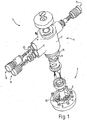
- the Fig. 1 Accordingly, for example, shows a perspective top view of a water filter device 1 with a filter head 2 and a replaceable filter cartridge 3.
- the filter head consists of several filter head components, the housing 7, an inlet valve 8, an outlet valve 9, and a relaxation and / or flushing valve 10 and a Encryption Structure 5.
- a complementary encryption structure 4 is associated with the filter cartridge. These encryption structures 4, 5 are provided so that only permissible combinations of filter heads and filter cartridges are possible.
- the encryption structure 4 is formed on the end face 6 of the filter cartridge 3 in the axial direction.
- this encryption structure 4 exemplarily represents a tooth which engages in a corresponding complementary recess 5 on a filter head component 11. Only if the filter cartridge 3 associated element of the encryption structure 4, with the filter head component 11 associated encryption structure 5 matches, the filter cartridge in question can be mounted in the filter head.
- an optionally modified to this embodiment is conceivable, in which on one of the end face 6 associated element also in axial alignment, the encryption structure 4 is formed.
- Such an element could be, for example, a ring to be placed on the end face 6, a disk or the like, which is suitable for a corresponding connection with the filter candle for realizing such an encryption structure or its function.
- a possible connection between such Filter cartridge element and the filter cartridge would, for example, a screw, a bond, a clip and / or snap closure or the like.
- a separation between the encryption structure 4, 5 and the fixing structure 12 is provided for the attachment of the filter cartridge 3 to the filter head 2.
- the fixing structure 12 is formed here in the form of a bayonet closure 12, which forms a corresponding connection with the housing 7 when inserting the filter candle into the head 2, so that in the fixed state of the filter candle 3 the head and the candle form a corresponding water filter device 1.
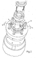
- the two encryption structures 4, 5 thus form a toothing, in which when a plurality of teeth these are in a certain angular relationship 14 to each other, such. B. shown in the FIG. 2 , with an offset of 180 °.
- the tooth 5 has a design 4 pointing away from the filter candle 3, which engages in a complementary recess 5 of the filter head component 11.
- a tooth 15 of the toothing z. B. formed on a filter head component 11 and the filter cartridge 3 juend engages in a correspondingly complementary recess.
- a combined training of such differently oriented teeth of the filter cartridge 13 pioneering or pointing to the filter cartridge 3, is possible and extends the possible spectrum of encryptions.
- a further supplement in this respect can be realized for example by radial offset of one or more teeth to each other, but always in axial alignment with an end face 6 of the filter cartridge 3.
- Another advantage of such an embodiment is seen in a simpler and easier insertability of the filter cartridge due to smaller or more compact structures.
- the encryption structure within the sealing region, behind a corresponding raw water inlet seal, which is realized for example in the form of an O-ring 17, which is particularly due to the separate formation of the fixing structure 12 and the encryption structures 4, 5.
- An additional extension of the encryption options is the different design of the teeth in terms of their length and / or size, but also in terms of a different arrangement and number of teeth, as exemplified here by the two teeth 15, 16 in the FIG. 2 are shown.
- a modified embodiment on the other hand, for example, but also 3, 4 or any other number of be arranged on the end face 6 of the filter 3 teeth may be provided.
- the angle segment 18 here exemplified only equipped with a single tooth. In a different embodiment, it may well be more.
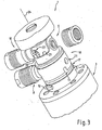
- the encryption structure 4, 5 as an actuating element for a filter head component 11, z. B. in the form of a valve body 9, as in the FIG. 3 represented, is formed.
- This valve body 19 in the FIG. 3 differs from the embodiment in the valve body in the FIG. 1 in that it is designed as a rotary valve body.
- valve bodies shown are exemplified as plunger valves.
- an intake valve 8 and an exhaust valve 9 are shown formed on the valve body 19 by way of example.
- Another possible arrangement of a valve on this valve body 19 is shown by the expansion valve 10 and / or the purge valve 10, which is realized here in the present case in a single valve.
- the inlet valve is used to control the raw water inflow, the outlet valve to control the filtrate flow.
- the expansion valve serves to reduce the prevailing in the interior of the water filter device pressure before removing the filter replacement candle, preferably via a correspondingly provided line (not shown here).
- the purge valve 10, which is also realized herewith, serves for rinsing the replaceable filter when it is inserted into the filter head, so that impurities possibly present therein can be flushed out and likewise disposed of via this discharge line.
- valve body 19 may include a control cam 21 or a control cam 20, which is actuated for a corresponding activation of the relevant valve at the respective actuation time or for the respective relative positioning position of the replacement filter cartridge 3 to the filter head 2.
- valve stem 22 is shown, which for reasons of simplification in the FIG. 1 designated with the number 22.
- expansion valve or flushing valve 10 is mutatis mutandis the same as that of the in the FIG. 3
- this is not a rotary valve, but a cam-operated and / or cam-operated plunger valve. This can vary depending on the desired function be actuated relatively short or operated to its function.
- valve body 19 may, for example, also be provided with a further valve 23, for example in the form of a bypass valve, eg to be able to provide a corresponding connection for a further unit.
- a further unit could be, for example, an additional water filter device, which may optionally be connected in parallel to this water filter device, to allow switching to a second water filter device, if necessary, when the filter cartridge of the first water filter should be exhausted.
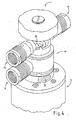
- FIG. 4 shows a contrast along a longitudinal axis 24 rotated representation of the same elements of the water filter device 1. Particularly well to recognize here is the control cam 20 for controlling the expansion valve 10 and the purge valve 10th
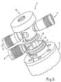
- FIG. 5 again shows a further illustration of a water filter device, but without valve body 19 to represent more, otherwise concealed by the valve body elements.
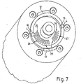
- a further element of the water filter device 1 is an adjusting device 25 for setting a partial flow ratio between at least two flow paths 26, 27 (FIG. FIG. 7 ) of the water filter device 1 through the inlet valve 8 supplied raw water flow.
- the flow path 26 is guided through the filter section of the replacement filter cartridge 3.
- the flow path 27 is guided via a so-called bypass section or bypass section in order to be able to intersect or prepare the filtrate stream of the water filter device 1 supplied by the flow path 26.
- the adjusting device 25 comprises a raw water distribution element 28 and a complementary partial flow channel guide element 29, which is best shown in the illustration of FIG. 7 is apparent.
- the partial flow channel guide element 29 in this case comprises the two inlet openings 35, 36 for the two partial flow sections, filter section 26 or bypass section 27, as the filter cartridge 3 associated elements.
- the untreated water distribution element 28 is here formed by way of example annular, has segment-like sections with recesses 30, 31 and covers 32, 33, which control the supplied via the inlet valve raw water flow, the two flow paths 26, 27, depending on the relative angular position to each other more or less covers or releases.
- a control of the water quality treated by this water filter device 1 is determined by the ratio between the filtrate flow and the bypass flow, e.g. by pressing a designated wheel 34 possible.
- the untreated water distribution element 28 and the partial flow channel guide element 29 may be configured or adjustable relative to one another such that either an essentially equal total cross section is formed from the sum of the two partial flows or, in another embodiment, one each After setting different sized total cross section of the controlled partial flows. If the overall cross section remains largely the same, the internal pressure in the water filter device also remains substantially the same in all the trimming devices, so that the result is as uniform a filtering effect as possible over the entire adjustment range.
Landscapes
- Chemical & Material Sciences (AREA)
- Chemical Kinetics & Catalysis (AREA)
- Hydrology & Water Resources (AREA)
- Engineering & Computer Science (AREA)
- Environmental & Geological Engineering (AREA)
- Water Supply & Treatment (AREA)
- Life Sciences & Earth Sciences (AREA)
- Organic Chemistry (AREA)
- Health & Medical Sciences (AREA)
- Clinical Laboratory Science (AREA)
- Water Treatment By Sorption (AREA)
- Filtration Of Liquid (AREA)
- Separation Using Semi-Permeable Membranes (AREA)
- Domestic Plumbing Installations (AREA)
Applications Claiming Priority (3)
| Application Number | Priority Date | Filing Date | Title |
|---|---|---|---|
| DE102006044744.1A DE102006044744C5 (de) | 2006-09-20 | 2006-09-20 | Wasserfiltervorrichtung mit Verschlüsselungsstruktur |
| EP07818054.4A EP2063973B1 (de) | 2006-09-20 | 2007-09-05 | Wasserfiltervorrichtung mit verschlüsselungsstruktur |
| PCT/EP2007/007742 WO2008034523A1 (de) | 2006-09-20 | 2007-09-05 | Wasserfiltervorrichtung mit verschlüsselungsstruktur |
Related Parent Applications (2)
| Application Number | Title | Priority Date | Filing Date |
|---|---|---|---|
| EP07818054.4A Division EP2063973B1 (de) | 2006-09-20 | 2007-09-05 | Wasserfiltervorrichtung mit verschlüsselungsstruktur |
| EP07818054.4A Division-Into EP2063973B1 (de) | 2006-09-20 | 2007-09-05 | Wasserfiltervorrichtung mit verschlüsselungsstruktur |
Publications (2)
| Publication Number | Publication Date |
|---|---|
| EP2749336A1 EP2749336A1 (de) | 2014-07-02 |
| EP2749336B1 true EP2749336B1 (de) | 2019-10-09 |
Family
ID=38961892
Family Applications (2)
| Application Number | Title | Priority Date | Filing Date |
|---|---|---|---|
| EP14000356.7A Active EP2749336B1 (de) | 2006-09-20 | 2007-09-05 | Wasserfiltervorrichtung mit Verschlüsselungsstruktur |
| EP07818054.4A Revoked EP2063973B1 (de) | 2006-09-20 | 2007-09-05 | Wasserfiltervorrichtung mit verschlüsselungsstruktur |
Family Applications After (1)
| Application Number | Title | Priority Date | Filing Date |
|---|---|---|---|
| EP07818054.4A Revoked EP2063973B1 (de) | 2006-09-20 | 2007-09-05 | Wasserfiltervorrichtung mit verschlüsselungsstruktur |
Country Status (11)
| Country | Link |
|---|---|
| US (2) | US8394269B2 (enExample) |
| EP (2) | EP2749336B1 (enExample) |
| JP (1) | JP5290180B2 (enExample) |
| KR (2) | KR101638192B1 (enExample) |
| CN (1) | CN101553295B (enExample) |
| DE (1) | DE102006044744C5 (enExample) |
| DK (1) | DK2063973T3 (enExample) |
| ES (1) | ES2476246T3 (enExample) |
| PL (1) | PL2063973T3 (enExample) |
| RU (1) | RU2434665C2 (enExample) |
| WO (1) | WO2008034523A1 (enExample) |
Families Citing this family (32)
| Publication number | Priority date | Publication date | Assignee | Title |
|---|---|---|---|---|
| EP2298431B1 (en) * | 2005-07-20 | 2014-01-01 | 3M Innovative Properties Co. | Fluid filtration system |
| DE102006044744C5 (de) | 2006-09-20 | 2021-04-01 | Aquis Wasser-Luftsysteme GmbH Lindau, Zweigniederlassung Rebstein | Wasserfiltervorrichtung mit Verschlüsselungsstruktur |
| DE102008029533A1 (de) * | 2008-06-21 | 2009-12-24 | Krones Ag | Vorrichtung zum Handhaben, insbesondere Filtrieren von Flüssigkeiten |
| USD795390S1 (en) | 2008-08-08 | 2017-08-22 | Kx Technologies Llc. | Reverse osmosis push filter |
| US9233322B1 (en) | 2008-08-08 | 2016-01-12 | Kx Technologies Llc | Push filter with floating key lock |
| US8137551B1 (en) | 2008-08-08 | 2012-03-20 | Kx Technologies, Llc | Push filter with floating key lock |
| US11426685B2 (en) | 2008-08-08 | 2022-08-30 | Kx Technologies Llc | Push filter with floating key lock |
| US9901852B2 (en) | 2008-08-08 | 2018-02-27 | Kx Technologies Llc | Push filter with floating key lock |
| EP2328667B1 (en) * | 2008-09-16 | 2017-01-25 | 3M Innovative Properties Company | Filter cartridge and system using linear actuation |
| DE102010005390A1 (de) * | 2010-01-22 | 2011-07-28 | MAHLE International GmbH, 70376 | Filtereinrichtung |
| CN103459730B (zh) | 2011-03-15 | 2016-04-06 | 仕龙阀门公司 | 自动水龙头 |
| US9695579B2 (en) | 2011-03-15 | 2017-07-04 | Sloan Valve Company | Automatic faucets |
| MX359527B (es) * | 2011-06-21 | 2018-10-01 | Kinetico Incorporated | Sistema de tratamiento de agua. |
| KR101311654B1 (ko) * | 2011-11-02 | 2013-09-25 | 정휘동 | 유로전환 기능을 갖는 필터 조립체 |
| US9764263B2 (en) * | 2012-03-01 | 2017-09-19 | Caterpillar Inc. | Filter element |
| JP2017127841A (ja) * | 2016-01-22 | 2017-07-27 | 日本濾過器株式会社 | フィルタ及びバルブ装置 |
| US10905989B2 (en) * | 2018-05-16 | 2021-02-02 | Haier Us Appliance Solutions, Inc. | Electromagnet interface for a water filter assembly |
| US10913020B2 (en) * | 2018-05-16 | 2021-02-09 | Haier Us Appliance Solutions, Inc. | Magnetic interface for a water filter assembly |
| US11273397B2 (en) | 2018-09-13 | 2022-03-15 | Electrolux Home Products, Inc. | Filter base for electronic connection to mating filter housing assembly |
| USD948660S1 (en) | 2019-11-18 | 2022-04-12 | Electrolux Home Products, Inc. | Filter cartridge |
| USD946701S1 (en) | 2019-11-18 | 2022-03-22 | Electrolux Home Products, Inc. | Filter cartridge |
| US11413560B2 (en) | 2019-11-18 | 2022-08-16 | Electrolux Home Products, Inc. | Push filter with floating key lock |
| USD969270S1 (en) | 2019-11-18 | 2022-11-08 | Electrolux Home Products, Inc. | Filter cartridge |
| USD948659S1 (en) | 2019-11-18 | 2022-04-12 | Electrolux Home Products, Inc. | Filter cartridge |
| USD946702S1 (en) | 2019-11-18 | 2022-03-22 | Electrolux Home Products, Inc. | Filter cartridge |
| USD946699S1 (en) | 2019-11-18 | 2022-03-22 | Electrolux Home Products, Inc. | Filter cartridge |
| USD946703S1 (en) | 2019-11-18 | 2022-03-22 | Electrolux Home Products, Inc. | Filter cartridge |
| USD946700S1 (en) | 2019-11-18 | 2022-03-22 | Electrolux Home Products, Inc. | Filter cartridge |
| CA3105784A1 (en) * | 2020-03-06 | 2021-09-06 | Global Industrial Distribution Inc. | Bottle filler fountain |
| CN112156557A (zh) * | 2020-09-17 | 2021-01-01 | 广东万家乐燃气具有限公司 | 一种具有自锁水功能的过滤器及热水设备 |
| US11311827B1 (en) | 2021-12-31 | 2022-04-26 | ERD Paris, LLC | Water filter system head with interchangeable inlet and outlet connections |
| DE102023118228A1 (de) * | 2023-07-10 | 2025-01-16 | Aquis Systems AG | Wasserfilter und Verfahren zum Betreiben eines Wasserfilters |
Citations (3)
| Publication number | Priority date | Publication date | Assignee | Title |
|---|---|---|---|---|
| US5336406A (en) * | 1993-01-26 | 1994-08-09 | Elkay Manufacturing Company | Replaceable filter cartridge and head assembly with safety shut-off valve |
| US5914037A (en) * | 1997-11-24 | 1999-06-22 | Yen; Chiu-Sen | Filter device for a water filter |
| US20020166805A1 (en) * | 2001-03-21 | 2002-11-14 | Minns Gian D. | Filter assembly and method of manufacture |
Family Cites Families (32)
| Publication number | Priority date | Publication date | Assignee | Title |
|---|---|---|---|---|
| US3334754A (en) * | 1964-11-23 | 1967-08-08 | Marvel Eng Co | Filter head structure |
| US4515692A (en) * | 1983-05-06 | 1985-05-07 | Water Soft, Inc. | Water filter |
| SG67905A1 (en) * | 1988-06-04 | 1999-10-19 | Herding Entstaubung | Filter for the separation of solid particles from hot gaseous or liquid media |
| US5035797A (en) | 1990-02-14 | 1991-07-30 | Stanadyne Automotive Corp. | Key system for filter assembly |
| US5174337A (en) * | 1990-10-31 | 1992-12-29 | Erie Manufacturing Company | Water conditioner rotary valve |
| US5186829A (en) * | 1991-08-16 | 1993-02-16 | Stanadyne Automotive Corp. | Fuel filter key system |
| JPH06178972A (ja) * | 1992-12-14 | 1994-06-28 | Takuma Co Ltd | 浄水器 |
| JP3585586B2 (ja) * | 1995-07-28 | 2004-11-04 | 松下電器産業株式会社 | 浄水器付混合水栓 |
| JP2715371B2 (ja) * | 1995-12-28 | 1998-02-18 | クリタック株式会社 | 浄水装置 |
| US5693219A (en) * | 1996-01-31 | 1997-12-02 | Beauchamp; William J. | Apparatus for backwashing a water filter |
| US5826854A (en) * | 1996-06-07 | 1998-10-27 | Amana Refrigeration, Inc. | Fluid routing system |
| CN2375824Y (zh) * | 1999-06-03 | 2000-04-26 | 谭玉申 | 凸轮冲洗阀 |
| DE19958648A1 (de) | 1999-12-06 | 2001-06-07 | Brita Gmbh | Wasserfiltervorrichtung |
| US6949189B2 (en) * | 2000-04-20 | 2005-09-27 | Cuno Incorporated | Keyed filter assembly |
| US7407148B2 (en) * | 2000-04-20 | 2008-08-05 | 3M Innovative Properties Company | Rotary valve assembly for fluid filtration system |
| US6458269B1 (en) * | 2000-04-20 | 2002-10-01 | Cuno Incorporated | Keyed filter assembly |
| EP1775003B1 (en) * | 2000-05-12 | 2009-12-23 | Pall Corporation | Filtration systems |
| DE60140326D1 (de) * | 2000-05-12 | 2009-12-10 | Pall Corp | Filter |
| ATE516066T1 (de) * | 2000-08-11 | 2011-07-15 | Omnipure Filter Company Inc | Profilsystem für die verbindung von filterkartusche und filterhalter |
| FR2818917B1 (fr) * | 2000-12-28 | 2003-10-03 | Dan Vasilescu | Filtre pour la depollution particulaire des fluides |
| CN2520931Y (zh) * | 2002-01-14 | 2002-11-20 | 符福煜 | 家用全自动反冲洗水处理装置 |
| DE10231096B9 (de) * | 2002-07-10 | 2006-11-09 | Brita Gmbh | Filtervorrichtung und Innenbehälter für eine Filtervorrichtung |
| US6923910B2 (en) * | 2003-01-07 | 2005-08-02 | Cuno Incorporated | Filter cartridge having bypass feature |
| CN1938071A (zh) * | 2003-07-29 | 2007-03-28 | 3M创新有限公司 | 具有锁定特征的水过滤器适配器 |
| DE10353424B4 (de) * | 2003-11-15 | 2012-12-13 | Mahle Filtersysteme Gmbh | Flüssigkeitsfilter, insbesondere Ölfilter für ein Kraftfahrzeug, und zugehöriges Ringfilterelement |
| JP2008505761A (ja) * | 2004-07-12 | 2008-02-28 | インテグリス・インコーポレーテッド | 物質またはエネルギー移動カートリッジ |
| US7326342B2 (en) * | 2004-09-13 | 2008-02-05 | Baldwin Filters, Inc. | Fuel filter cartridge and keyed end cap |
| CN2741960Y (zh) * | 2004-10-28 | 2005-11-23 | 厦门建霖卫浴工业有限公司 | 净水器 |
| DE102005007022A1 (de) * | 2005-02-15 | 2006-10-26 | Mann + Hummel Gmbh | Filtereinrichtung |
| BRPI0606908A2 (pt) * | 2005-02-22 | 2009-07-28 | Baldwin Filters Inc | aparelho de filtro |
| KR100712266B1 (ko) * | 2005-03-24 | 2007-05-17 | 주식회사 피코그램 | 커넥터를 이용하여 용이하게 교체되는 정수용 필터, 및 이를 이용한 정수장치 |
| DE102006044744C5 (de) | 2006-09-20 | 2021-04-01 | Aquis Wasser-Luftsysteme GmbH Lindau, Zweigniederlassung Rebstein | Wasserfiltervorrichtung mit Verschlüsselungsstruktur |
-
2006
- 2006-09-20 DE DE102006044744.1A patent/DE102006044744C5/de not_active Expired - Fee Related
-
2007
- 2007-09-05 DK DK07818054.4T patent/DK2063973T3/da active
- 2007-09-05 KR KR1020097007910A patent/KR101638192B1/ko active Active
- 2007-09-05 EP EP14000356.7A patent/EP2749336B1/de active Active
- 2007-09-05 ES ES07818054.4T patent/ES2476246T3/es active Active
- 2007-09-05 PL PL07818054T patent/PL2063973T3/pl unknown
- 2007-09-05 RU RU2009114720/05A patent/RU2434665C2/ru active
- 2007-09-05 KR KR1020167007514A patent/KR101766608B1/ko not_active Expired - Fee Related
- 2007-09-05 JP JP2009528615A patent/JP5290180B2/ja not_active Expired - Fee Related
- 2007-09-05 CN CN2007800429443A patent/CN101553295B/zh active Active
- 2007-09-05 US US12/311,108 patent/US8394269B2/en not_active Expired - Fee Related
- 2007-09-05 WO PCT/EP2007/007742 patent/WO2008034523A1/de not_active Ceased
- 2007-09-05 EP EP07818054.4A patent/EP2063973B1/de not_active Revoked
-
2013
- 2013-03-12 US US13/815,586 patent/US9409794B2/en active Active
Patent Citations (3)
| Publication number | Priority date | Publication date | Assignee | Title |
|---|---|---|---|---|
| US5336406A (en) * | 1993-01-26 | 1994-08-09 | Elkay Manufacturing Company | Replaceable filter cartridge and head assembly with safety shut-off valve |
| US5914037A (en) * | 1997-11-24 | 1999-06-22 | Yen; Chiu-Sen | Filter device for a water filter |
| US20020166805A1 (en) * | 2001-03-21 | 2002-11-14 | Minns Gian D. | Filter assembly and method of manufacture |
Also Published As
| Publication number | Publication date |
|---|---|
| CN101553295B (zh) | 2013-04-24 |
| WO2008034523A1 (de) | 2008-03-27 |
| RU2009114720A (ru) | 2010-10-27 |
| RU2434665C2 (ru) | 2011-11-27 |
| EP2063973A1 (de) | 2009-06-03 |
| KR20090082357A (ko) | 2009-07-30 |
| ES2476246T3 (es) | 2014-07-14 |
| CN101553295A (zh) | 2009-10-07 |
| DE102006044744A1 (de) | 2008-03-27 |
| KR101766608B1 (ko) | 2017-08-08 |
| US20100018912A1 (en) | 2010-01-28 |
| DE102006044744C5 (de) | 2021-04-01 |
| EP2063973B1 (de) | 2014-04-02 |
| KR101638192B1 (ko) | 2016-07-08 |
| US8394269B2 (en) | 2013-03-12 |
| JP5290180B2 (ja) | 2013-09-18 |
| DE102006044744B4 (de) | 2017-11-02 |
| DK2063973T3 (da) | 2014-06-30 |
| US20130220909A1 (en) | 2013-08-29 |
| JP2010504192A (ja) | 2010-02-12 |
| KR20160038069A (ko) | 2016-04-06 |
| PL2063973T3 (pl) | 2015-01-30 |
| US9409794B2 (en) | 2016-08-09 |
| EP2749336A1 (de) | 2014-07-02 |
Similar Documents
| Publication | Publication Date | Title |
|---|---|---|
| EP2749336B1 (de) | Wasserfiltervorrichtung mit Verschlüsselungsstruktur | |
| EP2007683B1 (de) | Wasserfilter-kartuschensystem mit kombinierter verschneideventiltechnik und einstellvorrichtung in der kerze und im kopf | |
| DE69920818T2 (de) | Sequentieller mischplattenschieber | |
| DE69110630T2 (de) | Ausgabevorrichtungen mit Mehrwegehahn. | |
| EP2350506B1 (de) | Hydraulische ventilanordnung mit einem einen druckausgeglichen angeordneten schliesskörper aufweisenden einbauventil | |
| EP2108002A2 (de) | Wasserfiltervorrichtung mit stellorgan zur einstellung eines verschnittverhältnisses | |
| DE4318203C1 (de) | Drehschieber und dessen Verwendung | |
| EP2585742B1 (de) | Schaltvorrichtung für einen fluidstrom | |
| DE69228940T2 (de) | Drehventil | |
| DE19614653A1 (de) | Ventil | |
| DE10231096A1 (de) | Filtervorrichtung und Innenbehälter für eine Filtervorrichtung | |
| DE112014000535B4 (de) | Rückspülbarer Flüssigkeitsfilter | |
| DE102008041122A1 (de) | Keramikscheibenventil für einen Heißgetränkeautomaten | |
| DE102007010129B4 (de) | Wasserfilter-Kartuschensystem mit kombinierter Verschneideventiltechnik in der Kerze und Einstellvorrichtung im Kopf | |
| WO2011151023A1 (de) | Schaltvorrichtung zur leitung eines fluids | |
| DE10358085B3 (de) | Kältemittel-Ventilanordnung | |
| DE102017105074B4 (de) | Steuerventil für Mittenverriegelung sowie Nockenwellenversteller | |
| DE102006044746B4 (de) | Wasserfilter mit Verschneidevorrichtung | |
| EP1196248B1 (de) | Umschaltdüsenkopf für ein hochdruckreinigungsgerät | |
| DE102021101145A1 (de) | Verteilerventil für eine Kaffeemaschine, Kaffeemaschine mit einem solchen Verteilerventil, und Verfahren zum Verteilen von Medien auf Verbrauchsfunktionalitäten einer Kaffeemaschine | |
| DE102016104411A1 (de) | Ventileinsatz für ein Heizkörperventil und Heizkörper mit Heizkörperventil | |
| DE3023939A1 (de) | Mischventil zur steuerung eines wasserstromes | |
| DE2757447A1 (de) | Rueckspuelbare filtereinrichtung | |
| DE102007062922A1 (de) | Wasserfiltervorrichtung mit Stellorgan zur Einstellung eines Verschnittverhältnisses | |
| DE102005004553A1 (de) | Rückspülbare Filtereinrichtung mit Strömungsstörkörpern |
Legal Events
| Date | Code | Title | Description |
|---|---|---|---|
| 17P | Request for examination filed |
Effective date: 20140130 |
|
| AC | Divisional application: reference to earlier application |
Ref document number: 2063973 Country of ref document: EP Kind code of ref document: P |
|
| AK | Designated contracting states |
Kind code of ref document: A1 Designated state(s): AT BE BG CH CY CZ DE DK EE ES FI FR GB GR HU IE IS IT LI LT LU LV MC MT NL PL PT RO SE SI SK TR |
|
| PUAI | Public reference made under article 153(3) epc to a published international application that has entered the european phase |
Free format text: ORIGINAL CODE: 0009012 |
|
| RBV | Designated contracting states (corrected) |
Designated state(s): AT BE BG CH CY CZ DE DK EE ES FI FR GB GR HU IE IS IT LI LT LU LV MC MT NL PL PT RO SE SI SK TR |
|
| 17Q | First examination report despatched |
Effective date: 20160317 |
|
| STAA | Information on the status of an ep patent application or granted ep patent |
Free format text: STATUS: EXAMINATION IS IN PROGRESS |
|
| GRAP | Despatch of communication of intention to grant a patent |
Free format text: ORIGINAL CODE: EPIDOSNIGR1 |
|
| STAA | Information on the status of an ep patent application or granted ep patent |
Free format text: STATUS: GRANT OF PATENT IS INTENDED |
|
| INTG | Intention to grant announced |
Effective date: 20190507 |
|
| GRAS | Grant fee paid |
Free format text: ORIGINAL CODE: EPIDOSNIGR3 |
|
| GRAA | (expected) grant |
Free format text: ORIGINAL CODE: 0009210 |
|
| STAA | Information on the status of an ep patent application or granted ep patent |
Free format text: STATUS: THE PATENT HAS BEEN GRANTED |
|
| RAP1 | Party data changed (applicant data changed or rights of an application transferred) |
Owner name: AQUIS WASSER-LUFT-SYSTEME GMBH, LINDAU, ZWEIGNIEDE |
|
| AC | Divisional application: reference to earlier application |
Ref document number: 2063973 Country of ref document: EP Kind code of ref document: P |
|
| AK | Designated contracting states |
Kind code of ref document: B1 Designated state(s): AT BE BG CH CY CZ DE DK EE ES FI FR GB GR HU IE IS IT LI LT LU LV MC MT NL PL PT RO SE SI SK TR |
|
| REG | Reference to a national code |
Ref country code: GB Ref legal event code: FG4D Free format text: NOT ENGLISH |
|
| REG | Reference to a national code |
Ref country code: CH Ref legal event code: EP |
|
| REG | Reference to a national code |
Ref country code: DE Ref legal event code: R096 Ref document number: 502007016790 Country of ref document: DE |
|
| REG | Reference to a national code |
Ref country code: IE Ref legal event code: FG4D Free format text: LANGUAGE OF EP DOCUMENT: GERMAN |
|
| REG | Reference to a national code |
Ref country code: AT Ref legal event code: REF Ref document number: 1188109 Country of ref document: AT Kind code of ref document: T Effective date: 20191115 |
|
| REG | Reference to a national code |
Ref country code: CH Ref legal event code: NV Representative=s name: DENNEMEYER AG, CH |
|
| REG | Reference to a national code |
Ref country code: NL Ref legal event code: MP Effective date: 20191009 |
|
| REG | Reference to a national code |
Ref country code: LT Ref legal event code: MG4D |
|
| PG25 | Lapsed in a contracting state [announced via postgrant information from national office to epo] |
Ref country code: PT Free format text: LAPSE BECAUSE OF FAILURE TO SUBMIT A TRANSLATION OF THE DESCRIPTION OR TO PAY THE FEE WITHIN THE PRESCRIBED TIME-LIMIT Effective date: 20200210 Ref country code: FI Free format text: LAPSE BECAUSE OF FAILURE TO SUBMIT A TRANSLATION OF THE DESCRIPTION OR TO PAY THE FEE WITHIN THE PRESCRIBED TIME-LIMIT Effective date: 20191009 Ref country code: GR Free format text: LAPSE BECAUSE OF FAILURE TO SUBMIT A TRANSLATION OF THE DESCRIPTION OR TO PAY THE FEE WITHIN THE PRESCRIBED TIME-LIMIT Effective date: 20200110 Ref country code: LT Free format text: LAPSE BECAUSE OF FAILURE TO SUBMIT A TRANSLATION OF THE DESCRIPTION OR TO PAY THE FEE WITHIN THE PRESCRIBED TIME-LIMIT Effective date: 20191009 Ref country code: BG Free format text: LAPSE BECAUSE OF FAILURE TO SUBMIT A TRANSLATION OF THE DESCRIPTION OR TO PAY THE FEE WITHIN THE PRESCRIBED TIME-LIMIT Effective date: 20200109 Ref country code: NL Free format text: LAPSE BECAUSE OF FAILURE TO SUBMIT A TRANSLATION OF THE DESCRIPTION OR TO PAY THE FEE WITHIN THE PRESCRIBED TIME-LIMIT Effective date: 20191009 Ref country code: SE Free format text: LAPSE BECAUSE OF FAILURE TO SUBMIT A TRANSLATION OF THE DESCRIPTION OR TO PAY THE FEE WITHIN THE PRESCRIBED TIME-LIMIT Effective date: 20191009 Ref country code: LV Free format text: LAPSE BECAUSE OF FAILURE TO SUBMIT A TRANSLATION OF THE DESCRIPTION OR TO PAY THE FEE WITHIN THE PRESCRIBED TIME-LIMIT Effective date: 20191009 Ref country code: ES Free format text: LAPSE BECAUSE OF FAILURE TO SUBMIT A TRANSLATION OF THE DESCRIPTION OR TO PAY THE FEE WITHIN THE PRESCRIBED TIME-LIMIT Effective date: 20191009 Ref country code: PL Free format text: LAPSE BECAUSE OF FAILURE TO SUBMIT A TRANSLATION OF THE DESCRIPTION OR TO PAY THE FEE WITHIN THE PRESCRIBED TIME-LIMIT Effective date: 20191009 |
|
| PG25 | Lapsed in a contracting state [announced via postgrant information from national office to epo] |
Ref country code: IS Free format text: LAPSE BECAUSE OF FAILURE TO SUBMIT A TRANSLATION OF THE DESCRIPTION OR TO PAY THE FEE WITHIN THE PRESCRIBED TIME-LIMIT Effective date: 20200224 |
|
| REG | Reference to a national code |
Ref country code: DE Ref legal event code: R026 Ref document number: 502007016790 Country of ref document: DE |
|
| PLBI | Opposition filed |
Free format text: ORIGINAL CODE: 0009260 |
|
| PLAX | Notice of opposition and request to file observation + time limit sent |
Free format text: ORIGINAL CODE: EPIDOSNOBS2 |
|
| PG2D | Information on lapse in contracting state deleted |
Ref country code: IS |
|
| PG25 | Lapsed in a contracting state [announced via postgrant information from national office to epo] |
Ref country code: EE Free format text: LAPSE BECAUSE OF FAILURE TO SUBMIT A TRANSLATION OF THE DESCRIPTION OR TO PAY THE FEE WITHIN THE PRESCRIBED TIME-LIMIT Effective date: 20191009 Ref country code: CZ Free format text: LAPSE BECAUSE OF FAILURE TO SUBMIT A TRANSLATION OF THE DESCRIPTION OR TO PAY THE FEE WITHIN THE PRESCRIBED TIME-LIMIT Effective date: 20191009 Ref country code: RO Free format text: LAPSE BECAUSE OF FAILURE TO SUBMIT A TRANSLATION OF THE DESCRIPTION OR TO PAY THE FEE WITHIN THE PRESCRIBED TIME-LIMIT Effective date: 20191009 Ref country code: DK Free format text: LAPSE BECAUSE OF FAILURE TO SUBMIT A TRANSLATION OF THE DESCRIPTION OR TO PAY THE FEE WITHIN THE PRESCRIBED TIME-LIMIT Effective date: 20191009 Ref country code: IS Free format text: LAPSE BECAUSE OF FAILURE TO SUBMIT A TRANSLATION OF THE DESCRIPTION OR TO PAY THE FEE WITHIN THE PRESCRIBED TIME-LIMIT Effective date: 20200209 |
|
| 26 | Opposition filed |
Opponent name: BWT AG Effective date: 20200709 |
|
| PG25 | Lapsed in a contracting state [announced via postgrant information from national office to epo] |
Ref country code: SK Free format text: LAPSE BECAUSE OF FAILURE TO SUBMIT A TRANSLATION OF THE DESCRIPTION OR TO PAY THE FEE WITHIN THE PRESCRIBED TIME-LIMIT Effective date: 20191009 Ref country code: IT Free format text: LAPSE BECAUSE OF FAILURE TO SUBMIT A TRANSLATION OF THE DESCRIPTION OR TO PAY THE FEE WITHIN THE PRESCRIBED TIME-LIMIT Effective date: 20191009 |
|
| PLBB | Reply of patent proprietor to notice(s) of opposition received |
Free format text: ORIGINAL CODE: EPIDOSNOBS3 |
|
| PG25 | Lapsed in a contracting state [announced via postgrant information from national office to epo] |
Ref country code: SI Free format text: LAPSE BECAUSE OF FAILURE TO SUBMIT A TRANSLATION OF THE DESCRIPTION OR TO PAY THE FEE WITHIN THE PRESCRIBED TIME-LIMIT Effective date: 20191009 |
|
| PLBP | Opposition withdrawn |
Free format text: ORIGINAL CODE: 0009264 |
|
| PLBD | Termination of opposition procedure: decision despatched |
Free format text: ORIGINAL CODE: EPIDOSNOPC1 |
|
| REG | Reference to a national code |
Ref country code: DE Ref legal event code: R100 Ref document number: 502007016790 Country of ref document: DE |
|
| PG25 | Lapsed in a contracting state [announced via postgrant information from national office to epo] |
Ref country code: MC Free format text: LAPSE BECAUSE OF FAILURE TO SUBMIT A TRANSLATION OF THE DESCRIPTION OR TO PAY THE FEE WITHIN THE PRESCRIBED TIME-LIMIT Effective date: 20191009 |
|
| PLBM | Termination of opposition procedure: date of legal effect published |
Free format text: ORIGINAL CODE: 0009276 |
|
| GBPC | Gb: european patent ceased through non-payment of renewal fee |
Effective date: 20200905 |
|
| 27C | Opposition proceedings terminated |
Effective date: 20210211 |
|
| REG | Reference to a national code |
Ref country code: BE Ref legal event code: MM Effective date: 20200930 |
|
| PG25 | Lapsed in a contracting state [announced via postgrant information from national office to epo] |
Ref country code: LU Free format text: LAPSE BECAUSE OF NON-PAYMENT OF DUE FEES Effective date: 20200905 |
|
| PG25 | Lapsed in a contracting state [announced via postgrant information from national office to epo] |
Ref country code: FR Free format text: LAPSE BECAUSE OF NON-PAYMENT OF DUE FEES Effective date: 20200930 |
|
| PG25 | Lapsed in a contracting state [announced via postgrant information from national office to epo] |
Ref country code: GB Free format text: LAPSE BECAUSE OF NON-PAYMENT OF DUE FEES Effective date: 20200905 Ref country code: IE Free format text: LAPSE BECAUSE OF NON-PAYMENT OF DUE FEES Effective date: 20200905 Ref country code: BE Free format text: LAPSE BECAUSE OF NON-PAYMENT OF DUE FEES Effective date: 20200930 |
|
| PG25 | Lapsed in a contracting state [announced via postgrant information from national office to epo] |
Ref country code: TR Free format text: LAPSE BECAUSE OF FAILURE TO SUBMIT A TRANSLATION OF THE DESCRIPTION OR TO PAY THE FEE WITHIN THE PRESCRIBED TIME-LIMIT Effective date: 20191009 Ref country code: MT Free format text: LAPSE BECAUSE OF FAILURE TO SUBMIT A TRANSLATION OF THE DESCRIPTION OR TO PAY THE FEE WITHIN THE PRESCRIBED TIME-LIMIT Effective date: 20191009 Ref country code: CY Free format text: LAPSE BECAUSE OF FAILURE TO SUBMIT A TRANSLATION OF THE DESCRIPTION OR TO PAY THE FEE WITHIN THE PRESCRIBED TIME-LIMIT Effective date: 20191009 |
|
| PGFP | Annual fee paid to national office [announced via postgrant information from national office to epo] |
Ref country code: DE Payment date: 20220920 Year of fee payment: 16 Ref country code: AT Payment date: 20220919 Year of fee payment: 16 |
|
| PGFP | Annual fee paid to national office [announced via postgrant information from national office to epo] |
Ref country code: CH Payment date: 20220928 Year of fee payment: 16 |
|
| REG | Reference to a national code |
Ref country code: DE Ref legal event code: R119 Ref document number: 502007016790 Country of ref document: DE |
|
| REG | Reference to a national code |
Ref country code: CH Ref legal event code: PL |
|
| REG | Reference to a national code |
Ref country code: AT Ref legal event code: MM01 Ref document number: 1188109 Country of ref document: AT Kind code of ref document: T Effective date: 20230905 |
|
| PG25 | Lapsed in a contracting state [announced via postgrant information from national office to epo] |
Ref country code: CH Free format text: LAPSE BECAUSE OF NON-PAYMENT OF DUE FEES Effective date: 20230930 |
|
| PG25 | Lapsed in a contracting state [announced via postgrant information from national office to epo] |
Ref country code: AT Free format text: LAPSE BECAUSE OF NON-PAYMENT OF DUE FEES Effective date: 20230905 |
|
| PG25 | Lapsed in a contracting state [announced via postgrant information from national office to epo] |
Ref country code: DE Free format text: LAPSE BECAUSE OF NON-PAYMENT OF DUE FEES Effective date: 20240403 Ref country code: CH Free format text: LAPSE BECAUSE OF NON-PAYMENT OF DUE FEES Effective date: 20230930 Ref country code: AT Free format text: LAPSE BECAUSE OF NON-PAYMENT OF DUE FEES Effective date: 20230905 |