EP2748922B1 - Energieübertragungseinheit - Google Patents
Energieübertragungseinheit Download PDFInfo
- Publication number
- EP2748922B1 EP2748922B1 EP12745812.3A EP12745812A EP2748922B1 EP 2748922 B1 EP2748922 B1 EP 2748922B1 EP 12745812 A EP12745812 A EP 12745812A EP 2748922 B1 EP2748922 B1 EP 2748922B1
- Authority
- EP
- European Patent Office
- Prior art keywords
- energy
- partially
- input device
- electrical
- energy input
- Prior art date
- Legal status (The legal status is an assumption and is not a legal conclusion. Google has not performed a legal analysis and makes no representation as to the accuracy of the status listed.)
- Active
Links
Images


Classifications
-
- H—ELECTRICITY
- H02—GENERATION; CONVERSION OR DISTRIBUTION OF ELECTRIC POWER
- H02N—ELECTRIC MACHINES NOT OTHERWISE PROVIDED FOR
- H02N2/00—Electric machines in general using piezoelectric effect, electrostriction or magnetostriction
- H02N2/18—Electric machines in general using piezoelectric effect, electrostriction or magnetostriction producing electrical output from mechanical input, e.g. generators
-
- H—ELECTRICITY
- H10—SEMICONDUCTOR DEVICES; ELECTRIC SOLID-STATE DEVICES NOT OTHERWISE PROVIDED FOR
- H10N—ELECTRIC SOLID-STATE DEVICES NOT OTHERWISE PROVIDED FOR
- H10N30/00—Piezoelectric or electrostrictive devices
- H10N30/30—Piezoelectric or electrostrictive devices with mechanical input and electrical output, e.g. functioning as generators or sensors
Definitions
- the invention relates to an energy transmission device which has at least one energy input device and at least one energy generating device designed as a piezo element device.
- Such special conditions of use may be present, for example, if galvanic insulation of the components to be supplied with electrical energy has to take place, in particular if very high potential differences exist.
- Such conditions exist for example in high-voltage systems or in the research environment, for example in Van-de-Graaff accelerators.
- transformers can not be usefully used beyond that. This is due to the fact that transformers are usually formed with ferromagnetic cores or yokes, in order to increase their efficiency. However, such a ferromagnetic material is in a strong magnetic field, this may already be due to the external magnetic field in the saturation region. Accordingly, the ferromagnetic material is "unavailable" for purposes of stress transformation, so that there are corresponding problems.
- EMC Electromagnetic Compatibility
- / or for very strong (static) magnetic fields typically magnetic fields with field strengths ⁇ 0.1 Tesla, 0.25 Tesla, 0.5 Tesla, 0.75 Tesla, 1 , 0 Tesla, 1.25 Tesla, 1.5 Tesla, 1.75 Tesla respectively 2.0 Tesla
- electrical energy usually an electrical alternating current
- This piezocrystal is mechanically connected to a second piezocrystal, so that the mechanical deformation (oscillation) of the first piezocrystal is transferred to the second piezocrystal and leads here to the generation of a corresponding electrical voltage which can be dissipated via electrical contacts.
- Such piezo transducers usually have a very good electromagnetic compatibility even under difficult EMC conditions.
- piezocrystals are usually very insensitive to strong external magnetic fields and to radioactive radiation (especially gamma radiation).
- piezoelectric transducers have many advantages, there is a major disadvantage in the natural frequency spectrum (in particular resonant frequencies) or oscillation behavior (depending on the applied electrical voltage) of the input piezoelectric crystal, which converts electrical energy into mechanical oscillations.
- the resulting transmission characteristics of piezoelectric transducers often prove to be problematic in practice, even as far as the usability of such piezoelectric transducers in certain applications.
- an active medical implant is described with a power supply having a mechanical oscillator or rotor, which is set by movements of the implant carrier and / or external excitation in vibration or rotation and energetically connected to an electrical load and / or energy storage is that a part of the kinetic energy generated with the vibration or rotation is coupled into the consumer and / or energy storage.
- the invention solves this problem.
- an energy transmission device which has at least one energy input device and at least one energy generating device designed as a piezo element device be designed in such a way that the at least one energy input device is at least partially designed as an electric magnetic field generating device and configured and arranged such that it is at least partially and / or at least temporarily operates under active mediation of an external magnetic field, such that it exerts a Lorentz force on the at least one power generating device.
- the energy introduced into the at least one energy input device is at least temporarily and / or at least partially essentially of the same energy form as the energy generated and output by the at least one energy generating device. These are essentially electrical energy.
- the electrical transmission device Even if the basic form of energy does not change, it is nevertheless possible (and possibly also advantageous) for the electrical transmission device to have, for example, the electrical voltage, the electric current intensity and / or the frequency and / or the amplitude shape and / or the pulse width ratio is changed at least temporarily and / or at least partially. Such a change can take place in both directions, so that, for example, the electrical voltage can be "transformed up” or “down transformed". It may also be possible that the direction and / or the ratio of the change in value change, in particular as a function of a control pulse (that is, for example, according to a user specification).
- a piezoelectric element in the present context, if appropriate, all means to understand, which can convert a mechanical change in shape, a mechanical change in size and / or an applied mechanical pressure in an electrical signal (possibly vice versa), this conversion preferably directly and directly due to the internal Structure of the piezo element device takes place.
- a piezoelectric element can be understood to mean a piezoelectric crystal or a suitable arrangement of a plurality of piezoelectric crystals, it also being possible for further "ancillary components" to be included therein.
- an active mediation with an external field is to be understood in particular as meaning that the component in question (or the relevant components) would not be essentially functional in the absence of the relevant external field, but would at least have a significantly poorer efficiency and / or other adverse properties would occur.
- the external field can be any field, such as an electric field, an electrostatic field, an electromagnetic field Field, a magnetic field, a force field and the like act.
- the external field is also generated at least partially and / or at least temporarily by the energy transmission device itself.
- the energy transmission device is particularly suitable, for example in conjunction with magnetic resonance tomographs, particle accelerators (here in particular in connection with deflection magnets , Focusing magnets and the like) and the like.
- particle accelerators here in particular in connection with deflection magnets , Focusing magnets and the like
- shielding may even be undesirable on the contrary. This space can be saved, surfaces from which can desorb gases can be avoided, costs can be reduced and the like.
- the magnetic field may be in any desired manner a magnetic alternating field, a (substantially) static magnetic field, as well as a (substantially) static magnetic field, which is superimposed with a certain varying proportion. Incidentally, it is of course possible that in addition to the magnetic field and other fields can be superimposed.
- the at least one energy input device is at least partially designed as an electric magnetic field generating device, wherein it is preferred if the energy input device is at least partially designed as an electrical conductor loop device and / or at least partially as an electrical coil device.
- This can lead to an interaction of, for example, an external magnetic field and the "locally generated" magnetic field, so that, for example Forces may result on the energy input device and / or other components of the energy transmission device (in particular with the energy input device in contact components).
- Such a construction may prove to be particularly simple on the one hand, but on the other hand also comparatively effective and possibly also wear-resistant. As a result, if necessary, particularly small designs of the energy transmission device can be realized.
- the magnetic field generating device can be any desired electric magnetic field generating device, such that a varying "local" magnetic field can be generated by varying an applied electrical current.
- a suitable design for this particular electrical conductor loops and / or electrical coils preferably without ferromagnetic core
- a further preferred embodiment of the energy transmission device results when at least one energy input device is at least partially designed as a field gain device-free energy input device.
- electrically powered magnetic field generating devices such as coils
- a piece of ferromagnetic material such as ferrite cores, ferromagnetic magnetic yokes, and the like
- Such an embodiment may prove advantageous when comparatively weak external fields are present.
- At least one energy input device is designed and set up such that it is at least partially and / or at least temporarily exposed to electrical energy.
- the electrical energy may in particular be electrical alternating voltage.
- This makes it possible, for example, for an energy generating device coupled to the energy input device to generate different electrical signals, in particular different with regard to voltage, current intensity, frequency, waveform, pulse width ratio and the like.
- the energy transmission device can be used very flexibly.
- electrical energy is generally present in any case in connection with electrical or electronic structures, so that they can be "branched off” comparatively easily.
- the at least one energy input device can be particularly simple.
- a preferred embodiment of the energy transmission device may result if it is designed and set up such that the at least one energy input device at least partially and / or at least temporarily via at least one movement, in particular at least partially and / or at least temporarily via at least one translational movement and / or at least partially and / or at least temporarily acts on at least one rotational movement on the at least one energy generating device, in particular acts mechanically.
- Such an effect can, for example, result if at least parts of an electrical conductor loop or a coil are brought into contact substantially flush with a surface of a piezocrystal.
- a further preferred embodiment of the energy transmission device may result if it is constructed and arranged such that the at least one energy input device acts on the at least one energy generation device, in particular mechanically, at least partially and / or at least temporarily via a deformation movement.
- This may be, for example, a change in shape of the corresponding energy input device (in particular a conductor loop or an electrical coil), for example, such that a rectangular shape attempts to deform into an oval or similar.
- a change in size of the energy input device occurs, such as, for example, in the case of a circular conductor loop or coil, a radius increase or a radius reduction.
- a plurality of energy input devices and / or a plurality of energy production devices is provided in the energy transmission device.
- different gear ratios or reduction ratios of the input and output energies, voltages, currents, frequencies, pulse width ratios, etc. can be realized.
- a voltage increase or a voltage reduction by a certain factor can be realized.
- the total transferable amount of energy can be increased, which may be advantageous in certain applications.
- the interconnection can be changed in dependence on a control signal.
- a further preferred embodiment of an energy transmission device can result if it has a linear arrangement of at least one energy input device and at least one energy generating device, in particular a linear arrangement of a plurality energy input devices and / or a plurality of power generation devices.
- a particularly compact design it is possible on the one hand to realize a particularly compact design.
- combination effects can be realized, such as that in a conductor loop two sides of the conductor loop can generate a mechanical pressure (and thus an energy in the adjacent piezoelectric element), even if it is different piezoelectric elements.
- the compactness and effectiveness of the resulting energy transmission device can usually be further increased.
- a first possible embodiment of a power transmission unit 1 (power transmission device) is shown.
- the power transmission unit 1 is in the Fig. 1 a and 1 b are shown at different times; the current direction of the current flowing in the electrical coil 2 is reversed, which will be described in more detail below.
- the energy transmission unit 1 is arranged, for example, in a device (not shown) in which a stronger magnetic field 3 occurs during operation.
- a device may, for example, be deflection magnets of a particle accelerator or the (mostly static) magnetic field of a magnetic resonance tomograph.
- the power transmission unit 1 is accordingly exposed to the magnetic field 3.
- the energy transfer unit 1 consists of two blocks 4, in which in the present embodiment, two piezo elements 5 (this may be commercially available piezo elements 5 act) are arranged.
- the piezoelectric elements 5 are arranged spaced apart from each other with the interposition of a filling material 6, wherein piezoelectric elements 5 and filler 6 in the presently illustrated embodiment are firmly connected to each other, so that in each case a one-piece block 4 results.
- an electrode 7 is arranged in each case, so that the electrical voltages generated in the piezoelectric elements 5 are derived and can be tapped at contact terminals 8.
- the contact terminals 8 are each formed independently.
- the contact terminals 8 can suitably (partially) be connected in parallel and / or (partially) serially, so that an output current with a higher current intensity and / or with a higher voltage can be generated.
- an electric coil 2 is arranged flush on the "contact" between the two blocks 4.
- the arrangement of electrical coil 2 and blocks 4 can of course be realized and marketed as a one-piece assembly.
- the electric coil 2 is not necessarily provided with a circular cross section. Rather, it may also be an electrical coil (or an electrical Conductor loop) with an approximately rectangular cross-section or a "flattened oval" cross-section act (similar to a stadium in which two semicircles are each connected by a straight line route).
- straight conductor regions 9a, 9b of the electric coil 2 are arranged such that they are arranged over as large a distance as possible at the height of the respectively adjacent piezoelectric elements 5.
- Fig. 1b the energy transmission unit 1 is shown in the "reversed" phase position.
- the current flowing in the electric coil 2 flows in the opposite direction (for example, phase by 180 ° to in Fig. 1 a shown situation).
- the Lorentz forces 10a, 10b exerted on the piezoelectric elements 5 act in opposite directions.
- the generated electrical voltages differ accordingly in sign.
- F is the force 10 which exert the conductor regions 9a, 9b on the piezoelements 5
- B is the magnetic field strength of the magnetic field 3
- i is the current through the electrical coil 2
- I is the conductor length of the conductor regions 9a, 9b above the piezoelements 5 N is the number of turns of the electric coil 2.
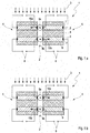
- Fig. 2 is shown in a schematic cross-sectional view, as a larger number of blocks 4 (similar to in Fig. 1 formed) with two piezoelectric elements 5 for forming a linearly arranged energy transfer unit 12 with respective intermediate electric coils 2 can be arranged linearly.
- four blocks 4 are used, wherein the number of blocks 4 may also be different (such as 3, 5, 6, 7, 8, 9 or 10 blocks 4).
- an electrical coil 2 is arranged, whereas on the outer sides 11 of the linearly arranged power transmission unit 12, no electric coils 2 are provided. This can of course be designed differently, ie with an electric coil 2 on one or both outer sides 11th
- linear coil power transmission unit 12 are used in each case connected so that they are alternately in the opposite Sense of electric current to be traversed.
- the electric coils 2a, 2c are thus connected in the same direction, whereas the middle electric coil 2b is connected opposite to the electric coils 2a, 2c.
- the linear array 12 is characterized significantly more effective.
- a third possible embodiment of a power transmission unit 13 is shown.
- the electric coil 14 "lying" between two piezo elements 5 is arranged.
- the force exerted by the piezoelectric elements 5 contacting conductor portions 15a, 15b of the electric coil 14 is therefore not based on a torque of the electric coil (as in the in Fig. 1 and Fig. 2 rather, it is based on shrinking ("pumping") the electrical coil 14. Since, as already mentioned, typically only micrometer motions are required, such "pumping" may be required. However, the electric coil 14 can be realized without causing excessive material fatigue of the conductor of the electric coil 14.
- the electric coil 14 does not necessarily have to have a circular cross-section here.
- substantially rectangular and / or "flattened oval" cross-sectional shapes can also be used here.
Landscapes
- General Electrical Machinery Utilizing Piezoelectricity, Electrostriction Or Magnetostriction (AREA)
Applications Claiming Priority (2)
| Application Number | Priority Date | Filing Date | Title |
|---|---|---|---|
| DE102011052923.3A DE102011052923B4 (de) | 2011-08-23 | 2011-08-23 | Energieübertragungseinheit |
| PCT/EP2012/064866 WO2013026652A1 (de) | 2011-08-23 | 2012-07-30 | Energieübertragungseinheit |
Publications (2)
| Publication Number | Publication Date |
|---|---|
| EP2748922A1 EP2748922A1 (de) | 2014-07-02 |
| EP2748922B1 true EP2748922B1 (de) | 2016-03-23 |
Family
ID=46642499
Family Applications (1)
| Application Number | Title | Priority Date | Filing Date |
|---|---|---|---|
| EP12745812.3A Active EP2748922B1 (de) | 2011-08-23 | 2012-07-30 | Energieübertragungseinheit |
Country Status (6)
| Country | Link |
|---|---|
| EP (1) | EP2748922B1 (pl) |
| DE (1) | DE102011052923B4 (pl) |
| DK (1) | DK2748922T3 (pl) |
| ES (1) | ES2569670T3 (pl) |
| PL (1) | PL2748922T3 (pl) |
| WO (1) | WO2013026652A1 (pl) |
Families Citing this family (2)
| Publication number | Priority date | Publication date | Assignee | Title |
|---|---|---|---|---|
| DE102012106376B4 (de) * | 2012-07-16 | 2016-09-08 | Gsi Helmholtzzentrum Für Schwerionenforschung Gmbh | Vorrichtung zur Energieerzeugung mit Piezoelementen |
| DE102018126909B4 (de) * | 2018-10-29 | 2023-07-27 | Hahn-Schickard-Gesellschaft für angewandte Forschung e.V. | Energiesammler zur Gewinnung elektrischer Energie bei zeitlich veränderbaren Magnetfeldern |
Citations (2)
| Publication number | Priority date | Publication date | Assignee | Title |
|---|---|---|---|---|
| DE102007059179A1 (de) * | 2007-12-06 | 2009-06-10 | Helmut Obieglo | Einrichtung mit Druckwandler |
| EP2221087A2 (de) * | 2009-02-20 | 2010-08-25 | Biotronik CRM Patent AG | Aktives medizinisches Implantat |
Family Cites Families (9)
| Publication number | Priority date | Publication date | Assignee | Title |
|---|---|---|---|---|
| JPS60501238A (ja) * | 1983-06-03 | 1985-08-01 | ピエゾ エレクトリツク プロダクツ,インコ−ポレ−テツド | 圧電流体発電機 |
| DE19910619A1 (de) * | 1999-03-10 | 2000-09-21 | Siemens Ag | Verfahren und Anordnung zum Versorgen eines elektrischen Verbrauchers mit elektrischer Energie über Schall |
| DE10025028C2 (de) * | 2000-05-20 | 2002-03-28 | Josef Roediger | Elektromagnetischer Festkörper-Spannungswandler |
| DE10103952A1 (de) * | 2001-01-30 | 2002-10-02 | Enocean Gmbh | Vorrichtung zur Energieversorgung eines Sensors |
| US20060049717A1 (en) * | 2004-09-08 | 2006-03-09 | Frank Liebenow | Transformer |
| DE102004055625B4 (de) * | 2004-11-11 | 2015-04-02 | Baumer Hübner GmbH | Spannungsgenerator mit einem piezoelektrischen Wandlerelement |
| MX2008015154A (es) * | 2006-06-22 | 2008-12-15 | Cooper Tire & Rubber Co | Generacion remota de energia magnetoestrictiva/piezoelectrica, bateria y metodo. |
| WO2009039293A1 (en) * | 2007-09-18 | 2009-03-26 | University Of Florida Research Foundation, Inc. | Dul-mode piezoelectric/magnetic vibrational energy harvester |
| DE102009010144A1 (de) * | 2009-02-23 | 2010-08-26 | Li-Tec Battery Gmbh | Verfahren und Ladevorrichtung zum Aufladen einer Kraftfahrzeugbatterie |
-
2011
- 2011-08-23 DE DE102011052923.3A patent/DE102011052923B4/de not_active Expired - Fee Related
-
2012
- 2012-07-30 EP EP12745812.3A patent/EP2748922B1/de active Active
- 2012-07-30 ES ES12745812.3T patent/ES2569670T3/es active Active
- 2012-07-30 WO PCT/EP2012/064866 patent/WO2013026652A1/de not_active Ceased
- 2012-07-30 PL PL12745812.3T patent/PL2748922T3/pl unknown
- 2012-07-30 DK DK12745812.3T patent/DK2748922T3/en active
Patent Citations (2)
| Publication number | Priority date | Publication date | Assignee | Title |
|---|---|---|---|---|
| DE102007059179A1 (de) * | 2007-12-06 | 2009-06-10 | Helmut Obieglo | Einrichtung mit Druckwandler |
| EP2221087A2 (de) * | 2009-02-20 | 2010-08-25 | Biotronik CRM Patent AG | Aktives medizinisches Implantat |
Also Published As
| Publication number | Publication date |
|---|---|
| DE102011052923A1 (de) | 2013-02-28 |
| DK2748922T3 (en) | 2016-06-27 |
| ES2569670T3 (es) | 2016-05-12 |
| PL2748922T3 (pl) | 2016-09-30 |
| WO2013026652A1 (de) | 2013-02-28 |
| DE102011052923B4 (de) | 2016-11-24 |
| EP2748922A1 (de) | 2014-07-02 |
Similar Documents
| Publication | Publication Date | Title |
|---|---|---|
| DE102012106376B4 (de) | Vorrichtung zur Energieerzeugung mit Piezoelementen | |
| DE102014100817A1 (de) | Konvertereinheit | |
| DE102010021094B4 (de) | Verbesserte elektrische Energieauskopplung aus piezoelektrischen Energiewandlern mit der Möglichkeit der Nachpolung dieser Energiewandler | |
| DE102013219536A1 (de) | Ladestation zum drahtlosen energietechnischen Koppeln eines elektrisch antreibbaren Fahrzeugs | |
| DE3833342A1 (de) | Piezomotor | |
| EP2748922B1 (de) | Energieübertragungseinheit | |
| DE112013006545T5 (de) | Magnetostriktive Vibrations-Leistungerzeugungsvorrichtung | |
| DE2010196A1 (de) | Schwingungswandler für Biegeschwinger | |
| DE102008032666A1 (de) | Kapazitive Wicklung für Elektromotoren, Transformatoren und Elektromagneten | |
| DE102011110870A1 (de) | Elektromechanischer Energiewandler | |
| EP2606565A2 (de) | Elektrischer dc/dc-wandler für eine mobile anwendung | |
| EP2003709B1 (de) | Piezokonverter mit Primärregelung und zugehöriger Piezotransformator | |
| WO2009030572A1 (de) | Piezoelektrischer energiewandler mit doppelmembran | |
| DE102017211936A1 (de) | Flacher einstellbarer Kondensator für Magnetresonanztomograph | |
| EP2562772A2 (de) | Induktives Bauteil | |
| DE102010018875A1 (de) | Piezogenerator mit verschiedenen Piezoelementen und elektronische Schaltung | |
| EP0984160B1 (de) | Spannungstransformator | |
| DE102016202922A1 (de) | Energieübertrager und Verfahren zum Betreiben eines Energieübertragers | |
| EP2852988B1 (de) | Generatoren aus elektroaktiven polymeren (eap) in differenzanordnung | |
| DE102008038989A1 (de) | Elektrische Anlage | |
| DE102004027847A1 (de) | Vorrichtung und Verfahren zur induktiven Energieübertragung | |
| WO2007143975A2 (de) | Verfahren zur galvanisch getrennten informations- und energieübertragung zwischen zwei elektronischen schaltungseinheiten | |
| WO2012045543A1 (de) | Spannungswandler mit mindestens einem elektro-mechanisch wirkenden schalter und entsprechendes verfahren | |
| DE102011006764A1 (de) | Piezotransformator, Verfahren zum Herstellen eines Piezotransformators und Inverter mit einem Piezotransformator | |
| DE102014113925A1 (de) | Energiewandler |
Legal Events
| Date | Code | Title | Description |
|---|---|---|---|
| PUAI | Public reference made under article 153(3) epc to a published international application that has entered the european phase |
Free format text: ORIGINAL CODE: 0009012 |
|
| 17P | Request for examination filed |
Effective date: 20140225 |
|
| AK | Designated contracting states |
Kind code of ref document: A1 Designated state(s): AL AT BE BG CH CY CZ DE DK EE ES FI FR GB GR HR HU IE IS IT LI LT LU LV MC MK MT NL NO PL PT RO RS SE SI SK SM TR |
|
| DAX | Request for extension of the european patent (deleted) | ||
| 17Q | First examination report despatched |
Effective date: 20150320 |
|
| GRAJ | Information related to disapproval of communication of intention to grant by the applicant or resumption of examination proceedings by the epo deleted |
Free format text: ORIGINAL CODE: EPIDOSDIGR1 |
|
| GRAP | Despatch of communication of intention to grant a patent |
Free format text: ORIGINAL CODE: EPIDOSNIGR1 |
|
| GRAP | Despatch of communication of intention to grant a patent |
Free format text: ORIGINAL CODE: EPIDOSNIGR1 |
|
| INTG | Intention to grant announced |
Effective date: 20151001 |
|
| GRAS | Grant fee paid |
Free format text: ORIGINAL CODE: EPIDOSNIGR3 |
|
| GRAA | (expected) grant |
Free format text: ORIGINAL CODE: 0009210 |
|
| AK | Designated contracting states |
Kind code of ref document: B1 Designated state(s): AL AT BE BG CH CY CZ DE DK EE ES FI FR GB GR HR HU IE IS IT LI LT LU LV MC MK MT NL NO PL PT RO RS SE SI SK SM TR |
|
| REG | Reference to a national code |
Ref country code: GB Ref legal event code: FG4D Free format text: NOT ENGLISH |
|
| REG | Reference to a national code |
Ref country code: CH Ref legal event code: EP |
|
| REG | Reference to a national code |
Ref country code: AT Ref legal event code: REF Ref document number: 784032 Country of ref document: AT Kind code of ref document: T Effective date: 20160415 Ref country code: CH Ref legal event code: NV Representative=s name: E. BLUM AND CO. AG PATENT- UND MARKENANWAELTE , CH |
|
| REG | Reference to a national code |
Ref country code: IE Ref legal event code: FG4D Free format text: LANGUAGE OF EP DOCUMENT: GERMAN |
|
| REG | Reference to a national code |
Ref country code: DE Ref legal event code: R096 Ref document number: 502012006423 Country of ref document: DE |
|
| REG | Reference to a national code |
Ref country code: ES Ref legal event code: FG2A Ref document number: 2569670 Country of ref document: ES Kind code of ref document: T3 Effective date: 20160512 |
|
| REG | Reference to a national code |
Ref country code: DK Ref legal event code: T3 Effective date: 20160623 |
|
| REG | Reference to a national code |
Ref country code: SE Ref legal event code: TRGR |
|
| REG | Reference to a national code |
Ref country code: FR Ref legal event code: PLFP Year of fee payment: 5 |
|
| REG | Reference to a national code |
Ref country code: LT Ref legal event code: MG4D |
|
| REG | Reference to a national code |
Ref country code: NL Ref legal event code: MP Effective date: 20160323 |
|
| PG25 | Lapsed in a contracting state [announced via postgrant information from national office to epo] |
Ref country code: NO Free format text: LAPSE BECAUSE OF FAILURE TO SUBMIT A TRANSLATION OF THE DESCRIPTION OR TO PAY THE FEE WITHIN THE PRESCRIBED TIME-LIMIT Effective date: 20160623 Ref country code: HR Free format text: LAPSE BECAUSE OF FAILURE TO SUBMIT A TRANSLATION OF THE DESCRIPTION OR TO PAY THE FEE WITHIN THE PRESCRIBED TIME-LIMIT Effective date: 20160323 Ref country code: FI Free format text: LAPSE BECAUSE OF FAILURE TO SUBMIT A TRANSLATION OF THE DESCRIPTION OR TO PAY THE FEE WITHIN THE PRESCRIBED TIME-LIMIT Effective date: 20160323 Ref country code: GR Free format text: LAPSE BECAUSE OF FAILURE TO SUBMIT A TRANSLATION OF THE DESCRIPTION OR TO PAY THE FEE WITHIN THE PRESCRIBED TIME-LIMIT Effective date: 20160624 |
|
| PG25 | Lapsed in a contracting state [announced via postgrant information from national office to epo] |
Ref country code: LV Free format text: LAPSE BECAUSE OF FAILURE TO SUBMIT A TRANSLATION OF THE DESCRIPTION OR TO PAY THE FEE WITHIN THE PRESCRIBED TIME-LIMIT Effective date: 20160323 Ref country code: LT Free format text: LAPSE BECAUSE OF FAILURE TO SUBMIT A TRANSLATION OF THE DESCRIPTION OR TO PAY THE FEE WITHIN THE PRESCRIBED TIME-LIMIT Effective date: 20160323 Ref country code: NL Free format text: LAPSE BECAUSE OF FAILURE TO SUBMIT A TRANSLATION OF THE DESCRIPTION OR TO PAY THE FEE WITHIN THE PRESCRIBED TIME-LIMIT Effective date: 20160323 Ref country code: RS Free format text: LAPSE BECAUSE OF FAILURE TO SUBMIT A TRANSLATION OF THE DESCRIPTION OR TO PAY THE FEE WITHIN THE PRESCRIBED TIME-LIMIT Effective date: 20160323 |
|
| PG25 | Lapsed in a contracting state [announced via postgrant information from national office to epo] |
Ref country code: EE Free format text: LAPSE BECAUSE OF FAILURE TO SUBMIT A TRANSLATION OF THE DESCRIPTION OR TO PAY THE FEE WITHIN THE PRESCRIBED TIME-LIMIT Effective date: 20160323 Ref country code: IS Free format text: LAPSE BECAUSE OF FAILURE TO SUBMIT A TRANSLATION OF THE DESCRIPTION OR TO PAY THE FEE WITHIN THE PRESCRIBED TIME-LIMIT Effective date: 20160723 |
|
| PG25 | Lapsed in a contracting state [announced via postgrant information from national office to epo] |
Ref country code: CZ Free format text: LAPSE BECAUSE OF FAILURE TO SUBMIT A TRANSLATION OF THE DESCRIPTION OR TO PAY THE FEE WITHIN THE PRESCRIBED TIME-LIMIT Effective date: 20160323 Ref country code: PT Free format text: LAPSE BECAUSE OF FAILURE TO SUBMIT A TRANSLATION OF THE DESCRIPTION OR TO PAY THE FEE WITHIN THE PRESCRIBED TIME-LIMIT Effective date: 20160725 Ref country code: SK Free format text: LAPSE BECAUSE OF FAILURE TO SUBMIT A TRANSLATION OF THE DESCRIPTION OR TO PAY THE FEE WITHIN THE PRESCRIBED TIME-LIMIT Effective date: 20160323 Ref country code: RO Free format text: LAPSE BECAUSE OF FAILURE TO SUBMIT A TRANSLATION OF THE DESCRIPTION OR TO PAY THE FEE WITHIN THE PRESCRIBED TIME-LIMIT Effective date: 20160323 Ref country code: SM Free format text: LAPSE BECAUSE OF FAILURE TO SUBMIT A TRANSLATION OF THE DESCRIPTION OR TO PAY THE FEE WITHIN THE PRESCRIBED TIME-LIMIT Effective date: 20160323 |
|
| PG25 | Lapsed in a contracting state [announced via postgrant information from national office to epo] |
Ref country code: BE Free format text: LAPSE BECAUSE OF NON-PAYMENT OF DUE FEES Effective date: 20160731 |
|
| REG | Reference to a national code |
Ref country code: DE Ref legal event code: R097 Ref document number: 502012006423 Country of ref document: DE |
|
| PLBE | No opposition filed within time limit |
Free format text: ORIGINAL CODE: 0009261 |
|
| STAA | Information on the status of an ep patent application or granted ep patent |
Free format text: STATUS: NO OPPOSITION FILED WITHIN TIME LIMIT |
|
| PG25 | Lapsed in a contracting state [announced via postgrant information from national office to epo] |
Ref country code: BG Free format text: LAPSE BECAUSE OF FAILURE TO SUBMIT A TRANSLATION OF THE DESCRIPTION OR TO PAY THE FEE WITHIN THE PRESCRIBED TIME-LIMIT Effective date: 20160623 |
|
| 26N | No opposition filed |
Effective date: 20170102 |
|
| PG25 | Lapsed in a contracting state [announced via postgrant information from national office to epo] |
Ref country code: MC Free format text: LAPSE BECAUSE OF FAILURE TO SUBMIT A TRANSLATION OF THE DESCRIPTION OR TO PAY THE FEE WITHIN THE PRESCRIBED TIME-LIMIT Effective date: 20160323 |
|
| REG | Reference to a national code |
Ref country code: IE Ref legal event code: MM4A |
|
| PG25 | Lapsed in a contracting state [announced via postgrant information from national office to epo] |
Ref country code: SI Free format text: LAPSE BECAUSE OF FAILURE TO SUBMIT A TRANSLATION OF THE DESCRIPTION OR TO PAY THE FEE WITHIN THE PRESCRIBED TIME-LIMIT Effective date: 20160323 |
|
| REG | Reference to a national code |
Ref country code: FR Ref legal event code: PLFP Year of fee payment: 6 |
|
| PG25 | Lapsed in a contracting state [announced via postgrant information from national office to epo] |
Ref country code: IE Free format text: LAPSE BECAUSE OF NON-PAYMENT OF DUE FEES Effective date: 20160730 |
|
| PG25 | Lapsed in a contracting state [announced via postgrant information from national office to epo] |
Ref country code: LU Free format text: LAPSE BECAUSE OF NON-PAYMENT OF DUE FEES Effective date: 20160730 |
|
| PG25 | Lapsed in a contracting state [announced via postgrant information from national office to epo] |
Ref country code: CY Free format text: LAPSE BECAUSE OF FAILURE TO SUBMIT A TRANSLATION OF THE DESCRIPTION OR TO PAY THE FEE WITHIN THE PRESCRIBED TIME-LIMIT Effective date: 20160323 Ref country code: HU Free format text: LAPSE BECAUSE OF FAILURE TO SUBMIT A TRANSLATION OF THE DESCRIPTION OR TO PAY THE FEE WITHIN THE PRESCRIBED TIME-LIMIT; INVALID AB INITIO Effective date: 20120730 |
|
| PG25 | Lapsed in a contracting state [announced via postgrant information from national office to epo] |
Ref country code: MK Free format text: LAPSE BECAUSE OF FAILURE TO SUBMIT A TRANSLATION OF THE DESCRIPTION OR TO PAY THE FEE WITHIN THE PRESCRIBED TIME-LIMIT Effective date: 20160323 Ref country code: MT Free format text: LAPSE BECAUSE OF FAILURE TO SUBMIT A TRANSLATION OF THE DESCRIPTION OR TO PAY THE FEE WITHIN THE PRESCRIBED TIME-LIMIT Effective date: 20160323 |
|
| REG | Reference to a national code |
Ref country code: FR Ref legal event code: PLFP Year of fee payment: 7 |
|
| PG25 | Lapsed in a contracting state [announced via postgrant information from national office to epo] |
Ref country code: TR Free format text: LAPSE BECAUSE OF FAILURE TO SUBMIT A TRANSLATION OF THE DESCRIPTION OR TO PAY THE FEE WITHIN THE PRESCRIBED TIME-LIMIT Effective date: 20160323 Ref country code: AL Free format text: LAPSE BECAUSE OF FAILURE TO SUBMIT A TRANSLATION OF THE DESCRIPTION OR TO PAY THE FEE WITHIN THE PRESCRIBED TIME-LIMIT Effective date: 20160323 |
|
| PGFP | Annual fee paid to national office [announced via postgrant information from national office to epo] |
Ref country code: ES Payment date: 20250819 Year of fee payment: 14 |
|
| PGFP | Annual fee paid to national office [announced via postgrant information from national office to epo] |
Ref country code: DK Payment date: 20250723 Year of fee payment: 14 Ref country code: DE Payment date: 20250722 Year of fee payment: 14 |
|
| PGFP | Annual fee paid to national office [announced via postgrant information from national office to epo] |
Ref country code: PL Payment date: 20250717 Year of fee payment: 14 Ref country code: IT Payment date: 20250731 Year of fee payment: 14 |
|
| PGFP | Annual fee paid to national office [announced via postgrant information from national office to epo] |
Ref country code: GB Payment date: 20250724 Year of fee payment: 14 |
|
| PGFP | Annual fee paid to national office [announced via postgrant information from national office to epo] |
Ref country code: FR Payment date: 20250723 Year of fee payment: 14 Ref country code: AT Payment date: 20250721 Year of fee payment: 14 |
|
| PGFP | Annual fee paid to national office [announced via postgrant information from national office to epo] |
Ref country code: CH Payment date: 20250801 Year of fee payment: 14 Ref country code: SE Payment date: 20250723 Year of fee payment: 14 |